CN107405015B - Modular floor covering seaming apparatus and method - Google Patents
Modular floor covering seaming apparatus and method Download PDFInfo
- Publication number
- CN107405015B CN107405015B CN201580071991.5A CN201580071991A CN107405015B CN 107405015 B CN107405015 B CN 107405015B CN 201580071991 A CN201580071991 A CN 201580071991A CN 107405015 B CN107405015 B CN 107405015B
- Authority
- CN
- China
- Prior art keywords
- floor covering
- covering unit
- connector
- edge
- clip
- Prior art date
- Legal status (The legal status is an assumption and is not a legal conclusion. Google has not performed a legal analysis and makes no representation as to the accuracy of the status listed.)
- Expired - Fee Related
Links
Images


Classifications
-
- A—HUMAN NECESSITIES
- A47—FURNITURE; DOMESTIC ARTICLES OR APPLIANCES; COFFEE MILLS; SPICE MILLS; SUCTION CLEANERS IN GENERAL
- A47G—HOUSEHOLD OR TABLE EQUIPMENT
- A47G27/00—Floor fabrics; Fastenings therefor
- A47G27/04—Carpet fasteners; Carpet-expanding devices ; Laying carpeting; Tools therefor
- A47G27/0475—Laying carpet tiles
- A47G27/0481—Connecting means therefor
-
- A—HUMAN NECESSITIES
- A47—FURNITURE; DOMESTIC ARTICLES OR APPLIANCES; COFFEE MILLS; SPICE MILLS; SUCTION CLEANERS IN GENERAL
- A47G—HOUSEHOLD OR TABLE EQUIPMENT
- A47G27/00—Floor fabrics; Fastenings therefor
- A47G27/04—Carpet fasteners; Carpet-expanding devices ; Laying carpeting; Tools therefor
- A47G27/0437—Laying carpeting, e.g. wall-to-wall carpeting
- A47G27/045—Gripper strips; Seaming strips; Edge retainers
- A47G27/0462—Tack strips for tensioning or seaming
Landscapes
- Floor Finish (AREA)
- Engineering & Computer Science (AREA)
- Architecture (AREA)
- Civil Engineering (AREA)
- Structural Engineering (AREA)
- Connector Housings Or Holding Contact Members (AREA)
Abstract
Description
技术领域technical field
本发明涉及地毯的领域,且更具体地涉及用于在连结模块化地板覆盖物单元的相邻部段中使用的设备。更具体地,本发明涉及一种设备和一种用于将所述设备用作连接器以便将多个模块化地板覆盖物单元连结到彼此和连结到支撑表面的方法。The present invention relates to the field of carpets, and more particularly to apparatus for use in joining adjacent sections of modular floor covering units. More particularly, the present invention relates to an apparatus and a method for using the apparatus as a connector for joining a plurality of modular floor covering units to each other and to a support surface.
背景技术Background technique
在模块化地板覆盖物单元铺设的领域中,铺设此类地板覆盖物的已有方法通常涉及极为劳动密集且材料密集的过程。所述过程涉及使用粘合剂单个地粘合地板覆盖物单元。粘合剂是重的、难以涂覆、成本高、难以移除且易于失效的。使用现有技术方法,必须将粘合剂施用于整个支撑表面或地板覆盖物单元的整个底侧。该过程在劳动与金钱两方面的成本均高昂,并且如果将更换或移除地板覆盖物单元,则产生额外的成本。In the field of modular floor covering unit laying, existing methods of laying such floor coverings generally involve an extremely labor-intensive and material-intensive process. The process involves bonding the floor covering units individually using an adhesive. Adhesives are heavy, difficult to apply, expensive, difficult to remove and prone to failure. Using prior art methods, the adhesive must be applied to the entire support surface or the entire underside of the floor covering unit. This process is costly both in terms of labor and money, and incurs additional costs if the floor covering unit is to be replaced or removed.
本领域中已知的用于铺设模块化地板覆盖物单元的另一种方法涉及使用粘合剂式连接器将模块化地板覆盖物单元与相邻单元连接。现有技术的此类“连接器系统”允许模块化地板覆盖物“浮”在支撑表面的顶部上。这些现有技术系统使用粘合剂将相邻地板单元的边缘保持在一起。一种此类系统和方法是在2013年5月7日出版的美国专利号8,434,282(SYSTEM FOR CARPET TILE INSTALLATION)(Scott等人),所述专利通过引用整体地并入本文中。Scott等人中所描述的方法利用近似72平方毫米的单侧压敏粘合接片(tab),其具有可释放保护层以将模块化地板单元的四个部段连结在一起。使用这种方法铺设模块化地板覆盖物存在若干问题。Another method known in the art for laying up modular floor covering units involves the use of adhesive-type connectors to connect the modular floor covering units to adjacent units. Such "connector systems" of the prior art allow modular floor coverings to "float" on top of a support surface. These prior art systems use adhesives to hold the edges of adjacent floor units together. One such system and method is US Patent No. 8,434,282 (SYSTEM FOR CARPET TILE INSTALLATION) (Scott et al.), issued May 7, 2013, which is incorporated herein by reference in its entirety. The method described in Scott et al. utilizes approximately 72 square millimeters of single-sided pressure-sensitive adhesive tabs with a releasable protective layer to join together the four sections of the modular floor unit. There are several problems with laying modular floor coverings using this method.
模块化地板单元的性质通常是重的,且铺贴连接器(tile connector)与模块化地板单元之间的粘接相比于传统粘合剂是相对弱的。在Scott等人的铺贴连接器中,连接器由涂覆有粘合剂的惰性塑料形成。虽然连接器是耐水的,但是其并不完全防水。这可引起连接器在一些条件下失效。地板覆盖物单元不断地受到湿气的侵袭。Scott等人的现有技术要求连接器是耐水的,因为连接器仅在一侧(面向上的一侧)上具有粘合剂,从而使连接器更不容易受到来自底层地板的湿气的影响。然而,这忽略了由于连接器上方的湿气源引起的粘合剂失效。例如,诸如酒店的商业机构可能用蒸汽清洁通过Scott等人的类型的粘合剂式连接器所连接的地板覆盖物单元。此外,可能频繁地有液体泼洒在地板上,并且地板可能经历潮湿的冬天条件。这种“润湿”是自上方发生的,且湿气附吸(leech down)到现有技术连接器的面上,从而使得其高度易受湿气的影响且导致潜在的连接器失效。Modular floor units are generally heavy in nature and the bond between the tile connector and the modular floor unit is relatively weak compared to traditional adhesives. In the patch connector of Scott et al., the connector is formed from an inert plastic coated with an adhesive. Although the connector is water resistant, it is not completely waterproof. This can cause the connector to fail under some conditions. Floor covering units are constantly attacked by moisture. The prior art of Scott et al requires the connector to be water resistant because the connector has adhesive on only one side (the side facing up), making the connector less susceptible to moisture from the subfloor . However, this ignores adhesive failure due to a source of moisture above the connector. For example, a commercial establishment, such as a hotel, may steam clean floor covering units connected by an adhesive type connector of the Scott et al. type. Additionally, liquids may be spilled on the floor frequently, and the floor may experience wet winter conditions. This "wetting" occurs from above and moisture leechs down onto the faces of prior art connectors, making them highly susceptible to moisture and leading to potential connector failure.
Scott等人的类型的现有技术铺贴连接器在交通量大的区域中和沿模块化地板单元接缝具有高的失效率。来自办公室装备、步行交通量、座椅等的更重的交通量将应变(strain)置于这些连接器上。来自更重的交通量的应变可引起连接器以一种或多种方式失效。Prior art tile connectors of the type of Scott et al. have high failure rates in high traffic areas and along modular floor unit seams. Heavier traffic from office equipment, foot traffic, seating, etc. puts strain on these connectors. Strain from heavier traffic can cause the connector to fail in one or more ways.
Scott等人的类型的粘合剂式连接器的第一类型的失效是胶在重的力(诸如座椅滚动或使其他重物在地板覆盖物上运动)下将伸展或失效。为解决该问题,模块化地板覆盖物铺设工人可使用罐中的喷洒式粘合剂(spray adhesive)来补充这种类型的粘合剂式连接器系统,以给予模块化地板覆盖物的接缝额外强度。然而,这样做去除了这种类型的连接器系统的大部分优点,并且将挥发性有机化学物质(“VOA”)引入铺设区域中。存在于铺设区域中的VOC需要处于最小额外通风下,并且也可使在工作时间之后当区域经受远为更低的交通量时铺设模块化地板覆盖物成为必需。The first type of failure of the Scott et al. type of adhesive-type connector is that the glue will stretch or fail under heavy forces, such as seat rolling or moving other heavy objects over the floor covering. To solve this problem, modular floor covering layers can supplement this type of adhesive connector system with a spray adhesive in a can to give the modular floor covering a seam. extra strength. However, doing so removes most of the advantages of this type of connector system and introduces volatile organic chemicals ("VOAs") into the lay-up area. The VOCs present in the paved area need to be at minimum additional ventilation and can also necessitate the laying of modular floor coverings after working hours when the area experiences much lower traffic volumes.
如果沿一个方向存在过大的力,则出现第二类型的失效。如果此类力被施加在连接器上,则粘合剂式连接器将全部失效并使模块化地板单元在下方“挤在一起”,从而在下方引起能够从模块化地板单元的表面上方看到的“轮廓整形(profiling)”。A second type of failure occurs if there is too much force in one direction. If such a force were to be exerted on the connector, the adhesive-type connector would all fail and cause the modular floor unit to "squeeze together" underneath, causing the modular floor unit to be seen from above the surface of the modular floor unit below. "profiling".
此外,Scott等人的类型的现有技术连接器可仅与具有在制造过程中所使用的专属底背(例如,复合玻璃底背)的模块化地板覆盖物单元一起使用。Furthermore, prior art connectors of the type of Scott et al. can be used only with modular floor covering units with proprietary backings (eg, composite glass backings) used in the manufacturing process.
还存在用于沿长的笔直的接缝将地板覆盖材料的两个区段连结在一起的其他地毯接缝方法。此类方法包括在1998年9月1日出版的美国专利号5,800,664(CARPET SEAMINGAPPARATUS AND METHOD OF UTILIZING THE SAME)(Covert)和在2014年6月19日提交的美国专利申请号14/309,632(SEAMING APPARATUS AND METHOD)(LeBlanc等人),所述专利和所述专利申请两者通过引用整体地并入本文中。There are other carpet seaming methods for joining together two sections of floor covering along a long straight seam. Such methods include US Patent No. 5,800,664 (CARPET SEAMINGAPPARATUS AND METHOD OF UTILIZING THE SAME) (Covert), published September 1, 1998 and US Patent Application No. 14/309,632 (SEAMING APPARATUS), filed June 19, 2014. AND METHOD) (LeBlanc et al.), both the patent and the patent application are incorporated herein by reference in their entirety.
需要一种用于连结相邻模块化地板覆盖物单元的模块化地板覆盖物单元连接器,其耐受压力、侧向力、湿气、高交通量、重载荷以及过度磨损,其可被用在多种支撑表面上以连结多种类型的模块化地板覆盖物单元。There is a need for a modular floor covering unit connector for joining adjacent modular floor covering units that is resistant to pressure, lateral forces, moisture, high traffic, heavy loads, and excessive wear that can be used On a variety of support surfaces to join multiple types of modular floor covering units.
发明内容SUMMARY OF THE INVENTION
本发明的拼块地毯接缝设备或夹连器提供用于连结模块化拼块地板覆盖物单元的耐久接缝。相比于现有技术中的那些接缝,由夹连器固定的接缝既更牢固又更耐久。夹连器中所使用的压敏带是防水的,以在高交通量、频繁清洁的室内应用中提供耐磨性。The carpet tile seaming apparatus or clips of the present invention provide durable seams for joining modular tile floor covering units. Seams secured by clips are both stronger and more durable than those of the prior art. The pressure-sensitive tape used in the clip is waterproof to provide abrasion resistance in high-traffic, frequently cleaned indoor applications.
本发明的夹连器可包括具有0.40 mm的近似厚度的电镀锌钢卷金属板。在夹连器的制造中所使用的金属可包括100%的回收材料。夹连器的背侧可包括厚度为近似0.1 mm的压敏纤维带和也充当湿气屏障的可释放硅胶带保护层。夹连器可包括一组向上成角度的金属突起,所述金属突起彼此侧向地且竖直地相对。根据本发明的每个夹连器可包括直立突起,所述直立突起在两个轴线上(侧向地和纵向地)穿透地板覆盖物单元的底背。The clips of the present invention may comprise electro-galvanized steel coil metal sheets having an approximate thickness of 0.40 mm. The metals used in the manufacture of the clips may include 100% recycled materials. The backside of the clip may include a pressure sensitive fiber tape approximately 0.1 mm thick and a protective layer of releasable silicone tape that also acts as a moisture barrier. The clip may include a set of upwardly angled metal protrusions that are laterally and vertically opposite each other. Each clip according to the invention may comprise upstanding protrusions penetrating the bottom back of the floor covering unit in two axes (laterally and longitudinally).
可将在夹连器的角隅处开始并朝向中心向内突出的划线冲压于电镀锌板中,以帮助铺设工人将待由夹连器连结的模块化地板覆盖物单元的四个角隅排成行。划线可用作铺设工人的引导件,使得每模块化地板单元利用夹连器的近似1/4。夹连器可具有76 mm的近似长度和宽度。夹连器还可包括具有近似36 平方毫米的面积的平坦中心部。在铺设期间,夹连器将通常定位成使得夹连器的表面的1/4接触通过夹连器连结的每个地板覆盖物单元。Scoring lines starting at the corners of the clips and projecting inwardly towards the center can be punched into the electro-galvanized sheet to help the layman connect the four corners of the modular floor covering units to be joined by the clips line up. The score line can be used as a guide for the layman, allowing approximately 1/4 of the clips to be utilized per modular floor unit. The clips can have an approximate length and width of 76 mm. The clip may also include a flat central portion having an area of approximately 36 square millimeters. During layup, the clips will typically be positioned such that 1/4 of the surface of the clips contacts each floor covering unit joined by the clips.
其上可铺设夹连器的支撑表面或底层地板(诸如,混凝土)可能“出汗”,从而在夹连器下方产生湿气。任何粘合式系统(包括粘合剂式连接器)都将暴露于此湿气,并且如任何粘合剂那样,可能最终损坏从而潜在地引起粘合剂式连接器的失效。该湿气能够引起完全粘住的模块化地板覆盖物铺设和粘合剂式连接器地板覆盖物铺设的失效。当使用本发明的夹连器固定模块化地板覆盖物单元时,可释放硅胶层充当对“出汗”湿气的蒸气屏障。The support surface or subfloor (such as concrete) on which the clips may be laid may "sweat", creating moisture under the clips. Any bonded system, including adhesive connectors, will be exposed to this moisture and, as with any adhesive, may eventually damage thereby potentially causing the failure of the adhesive connector. This moisture can cause failure of fully tacky modular floor covering layups and adhesive connector floor covering layups. When the modular floor covering unit is secured using the clips of the present invention, the releasable silicone layer acts as a vapor barrier to "sweat" moisture.
用现有技术方法,在大区域中将模块化地板覆盖物单元铺设成笔直的行可能是困难的。本发明提供“钉扎”系统,所述系统在铺设过程期间使得铺设工人能够以一间隔将夹连器“钉扎”于底层地板以确保一行在一长串模块化地板的铺设中将保持正确(true)。在铺设过程期间这种“钉扎”实质上减少了人为误差,并减轻了必须重新铺设大量已铺设的模块化地板覆盖物单元的问题。铺设工人所使用的“钉扎”系统主要被用于协助铺设过程。如果“钉扎”系统由于来自底层地板的湿气而在未来失效,夹连器仍将不失效或运动,因为夹连器的直立突起将保持模块化地板覆盖物单元处于适当位置。夹连器的电镀也使夹连器不受到湿气的影响。Laying modular floor covering units in straight rows over large areas can be difficult with prior art methods. The present invention provides a "pinning" system that enables a layman to "pin" clips to the subfloor at intervals during the laying process to ensure that a row will remain correct in laying a long series of modular floors (true). This "pinning" substantially reduces human error during the laying process and alleviates the problem of having to re-lay a large number of laid modular floor covering units. The "pinning" system used by layers is primarily used to assist the laying process. If the "pinning" system fails in the future due to moisture from the subfloor, the clips will still not fail or move because the upstanding protrusions of the clips will hold the modular floor covering unit in place. The electroplating of the clips also makes the clips impervious to moisture.
不同于现有技术的粘合剂式连接器(其仅可与专属的模块化地板覆盖物单元底背一起使用),本发明的夹连器可与任何地板覆盖物单元的任何底背一起使用。如果不更换或不移除旧的地板覆盖物单元而是代替地在上方覆盖(如果地板覆盖物单元制造商批准这样的应用),那么也可使用本发明的夹连器。Unlike prior art adhesive-type connectors, which can only be used with proprietary modular floor covering unit backings, the clip connectors of the present invention can be used with any backing of any floor covering unit . The clips of the present invention may also be used if the old floor covering unit is not replaced or removed but is instead covered over (if the floor covering unit manufacturer approves such an application).
在一个实施例中,本发明提供一种用于连结模块化地板覆盖物的设备,所述设备包括:具有上表面和下表面的板,所述下表面大致光滑,且所述上表面具有周边边缘并被划分成平坦中央区和一组边缘区,所述一组边缘区沿所述周边边缘在所述周边边缘与所述平坦中央区之间横向地延伸;在与所述一组边缘区间隔开的位置处向上延伸的多个尖锐突起,所述突起具有顶部和主体部分,所述顶部渐缩以促进与地板覆盖物底背的刺穿接合,且所述主体以小于90度的角度从上表面向上延伸,且所述突起朝向所述中央区向内延伸;以及定位在所述下表面上的粘合剂层,所述粘合剂层由可释放底背覆盖;其中,所述板适于定位在支撑表面上以连结具有定位在所述板的所述上表面上的底背的一组模块化地板覆盖物单元,并且其中,所述多个尖锐突起适于接合所述底背以固定所述模块化地板覆盖物单元。In one embodiment, the present invention provides an apparatus for joining modular floor coverings, the apparatus comprising: a panel having an upper surface and a lower surface, the lower surface being substantially smooth, and the upper surface having a perimeter The edge is divided into a flat central region and a set of edge regions, the set of edge regions extending laterally along the peripheral edge between the peripheral edge and the flat central region; between the peripheral edge and the set of edge regions a plurality of pointed protrusions extending upwardly at spaced locations, the protrusions having a top portion and a main body portion, the top portion tapering to facilitate piercing engagement with a floor covering bottom back, and the main body at an angle of less than 90 degrees extending upwardly from the upper surface, and the protrusions extend inwardly toward the central region; and an adhesive layer positioned on the lower surface, the adhesive layer being covered by a releasable backing; wherein the A board is adapted to be positioned on a support surface to join a set of modular floor covering units having a base back positioned on the upper surface of the board, and wherein the plurality of sharp protrusions are adapted to engage the base back to secure the modular floor covering unit.
根据该实施例的设备还可包括其中所述上表面还包括一组划线。板可以是矩形。设备还可适于连结多个模块化地板覆盖物部段,其中,所述多个所述地板覆盖物部段中的每一个均由相等百分数的所述尖锐突起接合。板可包括电镀锌板。可释放底背可以是可释放硅底背。可释放底背可适于阻挡湿气。尖锐突起从所附接的近端到所述顶部的长度可以是5 mm。边缘区可包括两个侧向地取向的边缘区和两个纵向地取向的边缘区。所述边缘区中的尖锐突起可适于在侧向轴线和纵向轴线上接合所述地板覆盖物单元。所述边缘区中的尖锐突起可适于从多个方向接合所述地板覆盖物单元,并且其中,所述尖锐突起适于防止所述地板覆盖物单元沿由相邻地板覆盖物单元产生的接缝运动或远离所述接缝运动。The apparatus according to this embodiment may further include wherein the upper surface further includes a set of score lines. The plate can be rectangular. The apparatus may also be adapted to join a plurality of modular floor covering sections, wherein each of said plurality of said floor covering sections is engaged by an equal percentage of said sharpened protrusions. The sheet may comprise electro-galvanized sheet. The releasable backing may be a releasable silicon backing. The releasable backing can be adapted to block moisture. The length of the sharp protrusion from the attached proximal end to the top may be 5 mm. The edge regions may include two laterally oriented edge regions and two longitudinally oriented edge regions. The sharp protrusions in the edge region may be adapted to engage the floor covering unit on a lateral axis and a longitudinal axis. The sharp projections in the edge regions may be adapted to engage the floor covering units from multiple directions, and wherein the sharp projections are adapted to prevent the floor covering units from joining the floor covering units along contacts created by adjacent floor covering units. seam movement or away from the seam movement.
在另一个实施例中,本发明提供一种用于连结模块化地板覆盖物的设备,所述设备包括:具有上表面和下表面的板,所述下表面大致光滑,且所述上表面具有周边边缘并被划分成平坦中央区和一组边缘区,所述一组边缘区沿所述周边边缘在所述周边边缘与所述平坦中央区之间横向地延伸;在与所述一组边缘区间隔开的位置处向上延伸的多个尖锐突起,所述突起具有顶部和主体部分,所述顶部渐缩以促进与地板覆盖物底背的刺穿接合,且所述主体以小于90度的角度从上表面向上延伸,且所述突起朝向所述中央区向内延伸;并且其中,所述板适于定位在支撑表面上以连结具有定位在所述板的所述上表面上的底背的一组模块化地板覆盖物单元,并且其中,所述多个尖锐突起适于接合所述底背以固定所述模块化地板覆盖物单元。In another embodiment, the present invention provides an apparatus for joining modular floor coverings, the apparatus comprising: a panel having an upper surface and a lower surface, the lower surface being substantially smooth, and the upper surface having a perimeter edge and is divided into a flat central region and a set of edge regions extending laterally along the perimeter edge between the perimeter edge and the flat central region; between the perimeter edge and the flat central region; a plurality of sharp projections extending upwardly at spaced apart locations, the projections having a top portion and a main body portion, the top portion tapering to facilitate piercing engagement with the floor covering bottom back, and the main body at a less than 90 degree angle an angle extending upwardly from the upper surface and the protrusion extending inwardly towards the central region; and wherein the plate is adapted to be positioned on a support surface to join a base having a base positioned on the upper surface of the plate A set of modular floor covering units, and wherein the plurality of sharp projections are adapted to engage the base back to secure the modular floor covering units.
该实施例还可包括其中所述上表面还包括一组划线。板可以是矩形。设备还可适于连结多个模块化地板覆盖物部段,其中,所述多个所述地板覆盖物部段中的每一个均由相等百分数的所述尖锐突起接合。板可包括电镀锌板。设备还可包括定位在所述下表面上的粘合剂层,所述粘合剂层由可释放底背所覆盖。可释放底背可以是适于阻挡湿气的可释放硅底背。尖锐突起从所附接的近端到所述顶部的长度可以是5 mm。边缘区可包括两个侧向地取向的边缘区和两个纵向地取向的边缘区。所述边缘区中的尖锐突起可适于在侧向轴线和纵向轴线上接合所述地板覆盖物单元。所述边缘区中的尖锐突起可适于从多个方向接合所述地板覆盖物单元,并且其中,所述尖锐突起适于防止所述地板覆盖物单元沿由相邻地板覆盖物单元产生的接缝运动或远离所述接缝运动。This embodiment may also include wherein the upper surface further includes a set of score lines. The plate can be rectangular. The apparatus may also be adapted to join a plurality of modular floor covering sections, wherein each of said plurality of said floor covering sections is engaged by an equal percentage of said sharpened protrusions. The sheet may comprise electro-galvanized sheet. The device may also include an adhesive layer positioned on the lower surface, the adhesive layer covered by a releasable backing. The releasable backing may be a releasable silicon backing adapted to block moisture. The length of the sharp protrusion from the attached proximal end to the top may be 5 mm. The edge regions may include two laterally oriented edge regions and two longitudinally oriented edge regions. The sharp protrusions in the edge region may be adapted to engage the floor covering unit on a lateral axis and a longitudinal axis. The sharp projections in the edge regions may be adapted to engage the floor covering units from multiple directions, and wherein the sharp projections are adapted to prevent the floor covering units from joining the floor covering units along contacts created by adjacent floor covering units. seam movement or away from the seam movement.
在又一个实施例中,本发明提供一种用于连结模块化地板覆盖物的方法,所述方法包括:将连接器板放置在支撑表面上,所述连接器板包括:具有上表面和下表面的板,所述下表面大致光滑,且所述上表面具有周边边缘并被划分成平坦中央区和一组边缘区,所述一组边缘区沿所述周边边缘在所述周边边缘与所述平坦中央区之间横向地延伸;在与所述一组边缘区间隔开的位置处向上延伸的多个尖锐突起,所述突起具有顶部和主体部分,所述顶部渐缩以促进与地板覆盖物底背的刺穿接合,且所述主体以小于90度的角度从上表面向上延伸,且所述突起朝向所述中央区向内延伸;以及将具有底背的第一地板覆盖物单元定位在连接器板上,使得第一地板覆盖物单元的底背覆盖连接器板的上表面的第一部分;以及通过在第一地板覆盖物单元上施加压力将第一地板覆盖物单元固定在连接器板上,使得底背被连接器板的多个尖锐的直立突起穿透并与之接合。In yet another embodiment, the present invention provides a method for joining modular floor coverings, the method comprising: placing a connector board on a support surface, the connector board comprising: having an upper surface and a lower surface surface plate, the lower surface is generally smooth, and the upper surface has a peripheral edge and is divided into a flat central region and a set of edge regions along the peripheral edge between the peripheral edge and all extending laterally between said flat central regions; a plurality of pointed protrusions extending upwardly at locations spaced from said set of edge regions, said protrusions having a top portion and a main body portion, said top tapering to facilitate floor covering piercing engagement of a bottom back with the body extending upwardly from the upper surface at an angle of less than 90 degrees and the protrusion extending inwardly towards the central region; and positioning a first floor covering unit having a bottom back on the connector plate, causing the bottom back of the first floor covering unit to cover a first portion of the upper surface of the connector plate; and securing the first floor covering unit to the connector by applying pressure on the first floor covering unit board so that the bottom back is penetrated by and engaged with a plurality of sharp upstanding protrusions of the connector board.
该实施例还可包括其中所述上表面还包括一组划线,并且其中,第一地板覆盖物单元至少部分地由所述划线在所述连接器板上对齐。板可以是矩形。所述方法还可包括将具有底背的第二地板覆盖物单元定位在连接器板上,使得第二地板覆盖物单元的底背覆盖连接器板的上表面的第二部分;以及通过在第二地板覆盖物单元上施加压力将第二地板覆盖物单元固定在连接器板上,使得底背被连接器板的多个尖锐的直立突起穿透并与之接合。板可包括电镀锌板。连接器板还可包括定位在所述下表面上的粘合剂层,所述粘合剂层由可释放底背所覆盖。可释放底背可以是适于阻挡湿气的可释放硅底背,且所述方法还可包括在将连接器板放置在支撑表面上之前移除可释放底背,从而引起粘合剂层粘附于支撑表面。尖锐突起从所附接的近端到所述顶部的长度可以是5 mm。边缘区可包括两个侧向地取向的边缘区和两个纵向地取向的边缘区。所述边缘区中的尖锐突起可适于在侧向轴线和纵向轴线上接合所述地板覆盖物单元。所述边缘区中的尖锐突起可适于从多个方向接合所述地板覆盖物单元,并且其中,所述尖锐突起适于防止所述地板覆盖物单元沿由相邻地板覆盖物单元产生的接缝运动或远离所述接缝运动。This embodiment may further include wherein the upper surface further includes a set of score lines, and wherein the first floor covering unit is aligned at least in part on the connector plate by the score lines. The plate can be rectangular. The method may also include positioning a second floor covering unit having a backing on the connector board such that the backing of the second floor covering unit covers a second portion of the upper surface of the connector board; Applying pressure on the second floor covering unit secures the second floor covering unit to the connector plate such that the bottom back is penetrated by and engages the plurality of sharp upstanding protrusions of the connector plate. The sheet may comprise electro-galvanized sheet. The connector board may also include an adhesive layer positioned on the lower surface, the adhesive layer covered by the releasable backing. The releasable backing may be a releasable silicon backing adapted to block moisture, and the method may further include removing the releasable backing prior to placing the connector board on the support surface, thereby causing the adhesive layer to stick. Attached to the support surface. The length of the sharp protrusion from the attached proximal end to the top may be 5 mm. The edge regions may include two laterally oriented edge regions and two longitudinally oriented edge regions. The sharp protrusions in the edge region may be adapted to engage the floor covering unit on a lateral axis and a longitudinal axis. The sharp projections in the edge regions may be adapted to engage the floor covering units from multiple directions, and wherein the sharp projections are adapted to prevent the floor covering units from joining the floor covering units along contacts created by adjacent floor covering units. seam movement or away from the seam movement.
当结合附图时,从以下对其优选实施例的详细描述中将更容易显而易见到本发明的夹连器的额外特征和优点,附图中,同样的附图标记在若干视图中指代对应零件。Additional features and advantages of the clips of the present invention will become more readily apparent from the following detailed description of preferred embodiments thereof, when taken in conjunction with the accompanying drawings, in which like reference numerals refer to corresponding parts throughout the several views .
附图说明Description of drawings
为了促进本发明的完全理解,现参考附图,其中同样的数字引用同样的元件。这些附图不应被解释为限制本发明,而是旨在是示例性的并用于参考。In order to facilitate a complete understanding of the present invention, reference is now made to the accompanying drawings, wherein like numerals refer to like elements. These drawings should not be construed as limiting the invention, but are intended to be exemplary and for reference.
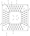
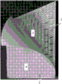
图1是本发明的夹连器的实施例的平面图。FIG. 1 is a plan view of an embodiment of the clip connector of the present invention.
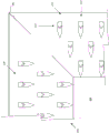
图2是本发明的夹连器的直立突起的实施例的平面图。Figure 2 is a plan view of an embodiment of the upright protrusion of the clip of the present invention.
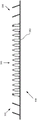
图3是本发明的夹连器的实施例的横截面视图。Figure 3 is a cross-sectional view of an embodiment of the clip of the present invention.
图4是本发明的夹连器的实施例的直立突起的横截面的详细视图。4 is a detailed view of a cross-section of an upstanding protrusion of an embodiment of a clip of the present invention.
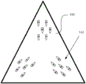
图5A是本发明的夹连器的另一实施例的平面图。5A is a plan view of another embodiment of the clip of the present invention.
图5B是本发明的夹连器的另一实施例的平面图。5B is a plan view of another embodiment of the clip of the present invention.
图6是本发明的夹连器的实施例中的可释放硅胶层和压敏纤维带的透视图。Figure 6 is a perspective view of the releasable silicone layer and pressure sensitive fiber tape in an embodiment of the clip of the present invention.
图7是本发明的夹连器的实施例的透视图。Figure 7 is a perspective view of an embodiment of the clip of the present invention.
具体实施方式Detailed ways
现在将参考如附图中所示的示例性实施例来更详细地描述本发明。尽管本文中参考示例性实施例描述本发明,但应理解的是,本发明并不限于此类示例性实施例。拥有本领域中普通技能且可获取本文中的教导的人员将认识到额外的实施方式、改型和实施例以及用于本发明的使用的其他应用,其在本文中被完全构想为在如本文中所公开和要求保护的本发明的范围内,并且关于以上各者而言本发明能够具有显著效用。The present invention will now be described in more detail with reference to exemplary embodiments as shown in the accompanying drawings. Although the invention is described herein with reference to exemplary embodiments, it should be understood that the invention is not limited to such exemplary embodiments. Those of ordinary skill in the art and having access to the teachings herein will recognize additional embodiments, modifications, and examples, as well as other applications for the use of the present invention, which are fully contemplated herein as described herein. within the scope of the invention disclosed and claimed in, and with respect to each of the above, the invention can have significant utility.
参考图1,提供本发明的夹连器100的实施例的平面图。夹连器100可包括具有0.40mm的近似厚度的电镀锌钢卷金属板。夹连器100的长度和宽度可以是76 mm,且夹连器100的中央区域150的长度和宽度可以是36 mm。夹连器100的边缘区域通过划线140被划分成四个部段130、132、134和136,每个部段具有一组直立突起110。划线140也协助铺设工人将待通过夹连器100连结的每个模块化地板覆盖物单元放置在夹连器100的表面的近似1/4上。可通过冲压过程形成夹连器100,其中,夹连器100由单片金属或其他合适材料形成。直立突起110和120与夹连器100的板同时形成,使得它们在通过冲压形成夹连器100时被整体地附接。1, a plan view of an embodiment of a
部段134中的直立突起110布置成行112和列114。该组直立突起110中的每个直立突起的宽度可以是1.4mm,且从近端到远端的长度可以是5 mm。每个直立突起110的长度被确定为长到足以穿透并固定模块化地板覆盖物单元,但并不过于长以至于完全刺穿地板覆盖物单元从而引起危险。突起110以近似70度的角度向上延伸,且从夹连器110的上表面到任何单个突起的远端的距离可以是4.7 mm。从同一行中的一个直立突起的近端到另一突起的远端的距离可以是7 mm。从一个突起的远端到相邻的交错的行中的突起的远端的距离可以是6 mm。一列中的每个突起之间的距离可以是5 mm。从列中最接近夹连器100的顶部或底部边缘的最后一个突起至边缘的距离可以是15 mm。突起110的列114是交错的,更接近夹连器110的中心的每列114比前一列少一个直立突起。直立突起110在夹连器110的侧向轴线上指向内,同时直立突起120在夹连器100的纵向轴线上指向内。夹连器100的背侧可包括一层厚度为近似0.1 mm的压敏纤维带和也可充当湿气屏障的可释放硅胶带保护层。The
另外,中央区域150可包括一层粘合剂,诸如丁基橡胶带或压敏纤维带,其可由可释放层所覆盖。中央区域150中的该额外粘合剂层可被用于进一步固定一些类型的模块化地板铺设单元。Additionally, the
在铺设任何夹连器100或地板覆盖物单元之前,可能需要预备底层地板或支撑表面。地板必须干净、干燥且无污垢、灰尘和油。在操作中,必须用HVAC使铺设场所适应。在测试和铺设之前、期间和之后,必须在48小时内维持地板和室内温度,以及地板铺设材料和粘合剂处于65°- 95°F下且湿度低于65%。当已化学地清洁了基底或当已化学地移除了粘合剂时,可能需要采取额外步骤以确保恰当铺设。在底层地板是混凝土的情况下,混凝土必须完全固化、不含湿气、无损、清洁并满足如美国混凝土协会委员会报告302.1.04 R中所限定的行业标准。新的混凝土需要近似90天的固化周期。对于旧的混凝土而言,必须针对湿气检查混凝土。干燥、满是灰尘、多孔的地板必须加以涂底漆或包封。对于木质地板而言,地板必须光滑并且水平。如果地板不平坦,那么将需要所批准的底衬。必须针对与粘合剂的相容性测试旧饰面或必须移除旧饰面,并对多孔木涂底漆。对于水磨石或大理石地板而言,所有灌浆线必须与合适的聚合物加强的水泥基修补面齐平。对于其他硬质表面而言,任何地板拼块均必须良好地固定到地板或被移除。破裂的、损坏的或松散的拼块必须被更换。Before laying any
为使用夹连器100铺设模块化地板覆盖物单元,将第一地板覆盖物单元定位成邻近毗连的地板覆盖物单元,使得夹连器100的1/4粘附于每个相邻地板覆盖物单元。以这种方式,夹连器跨过一个地板覆盖物单元的边缘与相邻地板覆盖物单元的边缘之间的间隙。可在下方的地板表面、底层地板上组装使用夹连器100铺设的地板覆盖物单元,而无需将地板覆盖物单元附接到地板表面。如果在大区域中期望,则可移除夹连器100的底部上的可释放硅胶带,并且可直接将夹连器100粘附于下方的地板表面。当在地板覆盖物单元的顶部上打印有图案时,这种铺设方法可以是期望的。在放置了一长串模块化地板单元之后,铺设工人在不将夹连器100粘附于地板表面的情况下可稍微偏离图案。将夹连器100粘附于地板表面使得铺设工人能够在大区域中保持相邻地板覆盖物单元的行处于笔直的线中。如果不移除可释放硅胶底背,那么其将相对下方的地板铺设表面(例如,混凝土)充当湿气屏障。To lay up modular floor covering
夹连器100的直立突起110和120在两个轴线上穿透地板覆盖物单元的底背。用拇指或钝工具牢牢地压在待使用夹连器100铺设的地板覆盖物单元上,以“开始”穿透过程。可沿地板覆盖物单元的接缝使用辊(诸如,三英寸的拖拉式辊),以使地板覆盖物单元安置于夹连器100上。这种安置引起直立突起110和120从近似70度的初始角度被向下按压至近似15度的最终角度。用橡胶锤或类似装置轻击地板覆盖物单元两次或三次,此举推动地板覆盖物单元使其在两个轴线上与夹连器100的板齐平,从而将地板覆盖物单元锁定在适当位置。当四个单元被放置在一起时,沿任何方向的任何力都使得地板覆盖物单元能够保持在适当位置。以这种方式,极大地减弱了失效的危险。在铺设过程中,铺设工人能够容易地将夹连器100从地板覆盖物单元的底背中拉出。如果大多数直立突起110和120自其原始取向没有弯曲超过45度的角度,那么可再次使用夹连器100。如果在铺设之后不久就被移除,那么可重新使用夹连器100以固定更换地板覆盖物单元。然而,如果在铺设之后数月或数年需要更换面板,则将很可能需要新的夹连器100,因为大多数(如果不是全部)直立突起110和120都将很可能已弯曲超过45度的角度。直立突起110和120的70度的角度确保人们将“感觉”不到通过地板覆盖物单元的突起。使用夹连器100铺设的地板覆盖物将贯穿整个地板覆盖物耗散力,而不是在单个夹连器100或接缝上施加张力。使用非粘合剂式方法完全排除粘合剂失效,且不产生任何烟气或将存在于完全粘住系统中的有害VOC。在现有技术的粘合剂式连接器系统中,在铺设期间,仍可需要铺设工人使用喷洒式粘合剂以便实现额外粘附,这可将烟气和VOC引入铺设环境中。The
可以以若干不同的图案铺设在铺设中所使用的地板覆盖物单元。对于“整体式”或网格状图案而言,将仅在两个或两个以上地板覆盖物单元之间的邻接点处的角隅处铺设夹连器100。对于偏移的图案而言,将需要将夹连器100铺设在两个或两个以上地板覆盖物单元之间的邻接点处的每个角隅处,这将需要将一些夹连器100铺设在一些地板覆盖物单元的侧向边缘或纵向边缘处。Floor covering units used in laying can be laid in several different patterns. For a "monolithic" or grid-like pattern, the
参考图2,提供了本发明的夹连器200的直立突起210的实施例的详细平面图。直立突起210的详细视图示出布置成行212和列214的突起210。直立突起210朝向夹连器200的中央区域250指向内。每组直立突起210包括三列齿(如果纵向地布置)(例如,直立突起210)或三列齿(如果侧向地布置)(例如,直立突起220)。划线240协助铺设工人在夹连器210上恰当地对齐地板覆盖物单元。Referring to Figure 2, a detailed plan view of an embodiment of the
现在参考图3,提供本发明的夹连器300的实施例的横截面视图。夹连器300的底表面360可包括纤维带粘合剂层和可释放硅底背层。可将底背层留在适当位置以充当蒸气屏障,或可将底背层移除以允许铺设工人在铺设过程期间将夹连器300“钉扎”在适当位置。“钉扎”允许铺设工人将夹连器300与其他夹连器排成行以确保在更大的铺设区域中地板覆盖物单元的笔直的线。两组直立凸起330和334被取向成在夹连器300的侧向轴线上指向内,同时可见的一组直立凸起336在纵向轴线上指向内。Referring now to FIG. 3, a cross-sectional view of an embodiment of a
现在参考图4,提供本发明的夹连器400的实施例的直立突起410和420的横截面的详细视图。直立突起410沿夹连器400的侧向轴线朝向该夹连器的中心指向内。多组直立突起410和420中的每个突起以近似70度的角度朝向夹连器400的中心抬高。每个直立突起的长度可以是5 mm,且每个远端自夹连器400的上表面抬高近似4.7 mm。夹连器400的底表面460可包括纤维带粘合剂层和可释放硅底背层。Referring now to FIG. 4, a detailed view of a cross-section of the
现在参考图5A和图5B,提供了本发明的圆形夹连器500和三角形夹连器510的实施例。圆形夹连器500可具有分区或分部段布置的多组直立凸起502以朝向圆形夹连器500的中心指向内。三角形夹连器510可具有分区或分部段布置的多组直立凸起512以朝向三角形夹连器510的中心指向内。本发明的夹连器还可包括任何其他形状以适应不同类型的地板覆盖物单元和地板覆盖物单元铺设图案。取决于期望的铺设应用,本发明的夹连器的形状可以为六边形、八边形、矩形或其他几何构形。Referring now to Figures 5A and 5B, embodiments of the
现在参考图6,提供本发明的夹连器600的实施例中的可释放硅胶层620和压敏纤维带610的透视图。如果未使用纤维带610将夹连器“钉扎”于地板表面上,则可释放硅胶层620可充当夹连器600的蒸气或湿气屏障。从该仰视透视图还可见开口,所述开口在形成在夹连器600的相对侧上向上突出的直立突起之后保留在夹连器600的板中。Referring now to FIG. 6, a perspective view of the
现在参考图7,提供本发明的夹连器700的实施例的透视图。夹连器700包括左侧向区730、顶部区732、右侧向区734和底部区736。所述区730、732、734和736中的每一者包括一组直立凸起,所述直立凸起布置成向内指向夹连器700的中心的三行或三列。在该透视图中,能够清楚地看到直立凸起的钉子形状和凸起的70度的角度。Referring now to FIG. 7, a perspective view of an embodiment of a
虽然已通过参考某些优选实施例描述了本发明,但应理解的是,可在所描述的本发明构思的精神和范围内作出众多改变。而且,本发明的范围将不受到本文中所描述的具体实施例的限制。应充分构想到,除了本文中所描述的实施例之外,本发明的其他各种实施例及对本发明的修改对于本领域普通技术人员将从前述描述和附图中变得显而易见。因此,预期此类其他实施例和修改落在以下所附权利要求的范围内。此外,虽然本文中已在具体实施例和实施方式及应用的背景中和在具体环境中描述了本发明,但本领域普通技术人员将认识的是,其有用性并不限于此,且能够出于任何数量的目的以任何数量的方式和在任何数量的环境中有益地应用本发明。因此,应鉴于如本文中所公开的本发明的完整广度和精神来解释下文所阐述的权利要求。While the present invention has been described with reference to certain preferred embodiments, it should be understood that numerous changes can be made within the spirit and scope of the inventive concept described. Furthermore, the scope of the present invention should not be limited by the specific embodiments described herein. It is fully contemplated that in addition to the embodiments described herein, various other embodiments of, and modifications to, the invention will become apparent to those of ordinary skill in the art from the foregoing description and drawings. Accordingly, such other embodiments and modifications are intended to fall within the scope of the following appended claims. Furthermore, while the invention has been described herein in the context of specific examples and implementations and applications and in a specific context, those of ordinary skill in the art will recognize that its usefulness is not limited thereto and can be The present invention is beneficially applied in any number of ways and in any number of contexts for any number of purposes. Therefore, the claims set forth below should be interpreted in view of the full breadth and spirit of the invention as disclosed herein.
Claims (17)
Applications Claiming Priority (3)
| Application Number | Priority Date | Filing Date | Title |
|---|---|---|---|
| US201462072729P | 2014-10-30 | 2014-10-30 | |
| US62/072729 | 2014-10-30 | ||
| PCT/US2015/015245 WO2016069044A1 (en) | 2014-10-30 | 2015-02-10 | Modular floor covering seaming apparatus and method |
Publications (2)
| Publication Number | Publication Date |
|---|---|
| CN107405015A CN107405015A (en) | 2017-11-28 |
| CN107405015B true CN107405015B (en) | 2020-06-12 |
Family
ID=55852071
Family Applications (1)
| Application Number | Title | Priority Date | Filing Date |
|---|---|---|---|
| CN201580071991.5A Expired - Fee Related CN107405015B (en) | 2014-10-30 | 2015-02-10 | Modular floor covering seaming apparatus and method |
Country Status (6)
| Country | Link |
|---|---|
| US (1) | US9353531B2 (en) |
| EP (1) | EP3212045B1 (en) |
| CN (1) | CN107405015B (en) |
| AU (2) | AU2015340006A1 (en) |
| NZ (1) | NZ732263A (en) |
| WO (1) | WO2016069044A1 (en) |
Families Citing this family (3)
| Publication number | Priority date | Publication date | Assignee | Title |
|---|---|---|---|---|
| US20180338631A1 (en) * | 2017-05-24 | 2018-11-29 | Judith Ellis | Floor mat fastening device |
| CN110638301A (en) * | 2019-10-17 | 2020-01-03 | 浙江道尔顿地毯有限公司 | Carpet fixing paste for fixing carpet and carpet fixing structure |
| NL2027075B1 (en) * | 2020-12-08 | 2022-07-07 | Tarkett B V | Surface covering connector |
Family Cites Families (31)
| Publication number | Priority date | Publication date | Assignee | Title |
|---|---|---|---|---|
| GB269278A (en) * | 1926-02-09 | 1927-04-21 | Bertram Bamber Baron | New or improved device for securing carpets and the like |
| US1931256A (en) * | 1929-06-12 | 1933-10-17 | Henry N Gundelach | Carpet, rug, and runner fastener |
| US2664589A (en) * | 1951-07-27 | 1954-01-05 | Chaim M Szpilberg | Carpet gripper |
| US2750621A (en) * | 1952-10-02 | 1956-06-19 | Joseph M White | Stair anchor |
| US3047903A (en) * | 1959-12-22 | 1962-08-07 | Walter J Reinhard | Rug anchoring tape |
| US3413678A (en) * | 1966-09-28 | 1968-12-03 | Joris M. Krantz | Carpet seam securing device |
| US3551939A (en) * | 1969-03-27 | 1971-01-05 | Keith E Rager | Stair carpet fasterner |
| US3693212A (en) * | 1969-12-10 | 1972-09-26 | James W Handy | Carpet anchoring means |
| GB1350767A (en) * | 1970-07-29 | 1974-04-24 | Gripperrods Ltd | Carpet fasteners |
| US3760454A (en) * | 1971-04-22 | 1973-09-25 | P Heinzel | Seaming tape for floor and ground coverings |
| US3950816A (en) * | 1974-12-06 | 1976-04-20 | Roberts Consolidated Industries, Inc. | Carpet gripper with headless carpet anchoring pins |
| US4340633A (en) * | 1980-03-14 | 1982-07-20 | Robbins Jr Edward S | Mat anchoring apparatus and method |
| US4970754A (en) * | 1989-08-11 | 1990-11-20 | Anderson Martin L | Carpet tack strip with urethane base |
| IT1262087B (en) * | 1993-03-17 | 1996-06-19 | Engen Meccanica Di Minen Ettor | AUTOMATIC MACHINE TO TIE BUNDLES OF TUBES OR SIMILAR |
| US5800664A (en) * | 1996-01-03 | 1998-09-01 | Covert; William H. | Carpet seaming apparatus and method of utilizing the same |
| GB9605951D0 (en) * | 1996-03-21 | 1996-05-22 | Milliken Denmark | Attachment plate |
| US20070204556A1 (en) * | 1996-07-19 | 2007-09-06 | Tac-Fast Georgia L.L.C. | Covering module and anchor sheet |
| US5815995A (en) * | 1996-08-01 | 1998-10-06 | Diversified Industrial Technologies, Inc. | Slip-resistant floor covering system |
| US5822828A (en) * | 1996-09-13 | 1998-10-20 | Interface, Inc. | Fastener for layered floor coverings and method of fastening layers |
| US5761765A (en) * | 1996-11-27 | 1998-06-09 | Fuzzell; Joe E. | Rug anchor |
| GB2334439A (en) * | 1998-02-23 | 1999-08-25 | Ykk Europ Ltd | Carpet fixing strip |
| US6216315B1 (en) * | 1999-06-30 | 2001-04-17 | Joe E. Fuzzell | Floor covering anchor |
| GB0009402D0 (en) * | 2000-04-18 | 2000-06-07 | Long Port Investments Ltd | Carpet gripper |
| CN1771372A (en) * | 2003-02-07 | 2006-05-10 | 温格公司 | Modular floor |
| US8353078B2 (en) * | 2010-03-24 | 2013-01-15 | CarptetLOK, LLC | Anchor and alignment device for carpet tiles |
| US20120073081A1 (en) * | 2010-09-28 | 2012-03-29 | Crenshaw Sr Earlie Lee | Rug hold down corner |
| DE102011012169A1 (en) * | 2011-02-23 | 2012-08-23 | Nora Systems Gmbh | Flooring |
| CA2920878C (en) * | 2012-08-16 | 2020-09-15 | Glen P. Greathouse | Tackless carpet strip |
| US20140113110A1 (en) * | 2012-10-19 | 2014-04-24 | Winfield Consumer Products, Inc. | Flexible vehicle surface protector with rigid nibs |
| US20140150206A1 (en) * | 2012-12-04 | 2014-06-05 | Milton Michael Currin | Apparatus and method for installing carpet |
| US9648972B2 (en) * | 2014-06-19 | 2017-05-16 | Armorlock Industries, Llc | Seaming apparatus and method |
-
2015
- 2015-02-10 EP EP15854725.7A patent/EP3212045B1/en active Active
- 2015-02-10 WO PCT/US2015/015245 patent/WO2016069044A1/en not_active Ceased
- 2015-02-10 AU AU2015340006A patent/AU2015340006A1/en not_active Abandoned
- 2015-02-10 CN CN201580071991.5A patent/CN107405015B/en not_active Expired - Fee Related
- 2015-02-10 NZ NZ732263A patent/NZ732263A/en not_active IP Right Cessation
- 2015-02-10 US US14/618,752 patent/US9353531B2/en not_active Expired - Fee Related
-
2020
- 2020-02-03 AU AU2020200756A patent/AU2020200756B2/en not_active Ceased
Also Published As
| Publication number | Publication date |
|---|---|
| AU2015340006A1 (en) | 2017-06-15 |
| EP3212045A1 (en) | 2017-09-06 |
| CN107405015A (en) | 2017-11-28 |
| US20160123019A1 (en) | 2016-05-05 |
| AU2020200756A1 (en) | 2020-02-20 |
| AU2020200756B2 (en) | 2021-09-16 |
| EP3212045A4 (en) | 2018-07-04 |
| EP3212045B1 (en) | 2022-06-01 |
| WO2016069044A1 (en) | 2016-05-06 |
| US9353531B2 (en) | 2016-05-31 |
| NZ732263A (en) | 2020-07-31 |
Similar Documents
| Publication | Publication Date | Title |
|---|---|---|
| US8302366B2 (en) | Mortarless tile installation system and method for installing tiles | |
| JP4680881B2 (en) | Floor board | |
| CA2899182C (en) | Flooring underlayment and apparatus, flooring system and floor installation method using the same | |
| US8490356B2 (en) | Mortarless tile installation system and method for installing tiles | |
| EP3157393B1 (en) | Seaming apparatus and method | |
| EP1329568A1 (en) | Composite tile for flooring | |
| AU2020200756B2 (en) | Modular floor covering seaming apparatus and method | |
| US20170138065A1 (en) | Support plate system for elevated flooring tiles | |
| CA2743287A1 (en) | Articles and methods for laying ceramic tile floor | |
| US6408584B1 (en) | Pre-fabricated wood underlayment and tile system | |
| CN100572721C (en) | Floor tiles and packaging method thereof | |
| JP3869553B2 (en) | Floor heating system construction method | |
| EP3296487B1 (en) | Support plate system for elevated flooring tiles | |
| JP3200478U (en) | Tile integrated tarpaulin | |
| DE8218767U1 (en) | NON-SLIP RAIL, IN PARTICULAR CARPET ROLL | |
| DE202017004616U1 (en) | Dimensionally stable surface for floor coverings | |
| JP6099181B1 (en) | Simple flooring construction method | |
| WO2007123393A1 (en) | Floor or wall covering removably fixed to an elastic intermediate layer by an adhesive | |
| JP2015203288A (en) | Floor tile construction method | |
| JPH0738398U (en) | Floorboard for laying | |
| KR20140050523A (en) | Installing method of flooring material for exhibition center and flooring material for exhibition center |
Legal Events
| Date | Code | Title | Description |
|---|---|---|---|
| PB01 | Publication | ||
| PB01 | Publication | ||
| SE01 | Entry into force of request for substantive examination | ||
| SE01 | Entry into force of request for substantive examination | ||
| GR01 | Patent grant | ||
| GR01 | Patent grant | ||
| CF01 | Termination of patent right due to non-payment of annual fee |
Granted publication date: 20200612 Termination date: 20220210 |
|
| CF01 | Termination of patent right due to non-payment of annual fee |