CN107326918B - Hidden type plugging impervious water collecting well penetrating through raft plates and construction process thereof - Google Patents
Hidden type plugging impervious water collecting well penetrating through raft plates and construction process thereof Download PDFInfo
- Publication number
- CN107326918B CN107326918B CN201710714179.0A CN201710714179A CN107326918B CN 107326918 B CN107326918 B CN 107326918B CN 201710714179 A CN201710714179 A CN 201710714179A CN 107326918 B CN107326918 B CN 107326918B
- Authority
- CN
- China
- Prior art keywords
- water
- well
- water collecting
- collecting well
- raft
- Prior art date
- Legal status (The legal status is an assumption and is not a legal conclusion. Google has not performed a legal analysis and makes no representation as to the accuracy of the status listed.)
- Active
Links
Images


Classifications
-
- E—FIXED CONSTRUCTIONS
- E02—HYDRAULIC ENGINEERING; FOUNDATIONS; SOIL SHIFTING
- E02D—FOUNDATIONS; EXCAVATIONS; EMBANKMENTS; UNDERGROUND OR UNDERWATER STRUCTURES
- E02D19/00—Keeping dry foundation sites or other areas in the ground
- E02D19/06—Restraining of underground water
- E02D19/10—Restraining of underground water by lowering level of ground water
Abstract
The invention discloses a hidden type impermeable water collecting well capable of being plugged by penetrating through a raft and a construction process thereof. According to the invention, a water collecting well penetrates through a raft plate and is welded on a main rib of the raft plate, a water pumping pipe and an exhaust pipe are arranged in the water collecting well, water is pumped and drained normally before well sealing, concrete is adopted to fill the space between the water collecting well and the water pumping pipe and the exhaust pipe in a normal water pumping state during well sealing, after the strength generated by concrete solidification can resist the pressure of underground water, valves on the water pumping pipe and the air inlet pipe are closed, the upper water pumping pipe and the upper air inlet pipe are removed from a movable joint position, the water pumping pipe and the upper air inlet pipe are tightly sealed by a plug, and concrete at the valve position is poured to complete well sealing. The structure and the process are simple, the operation is easy, the problem that the foundation construction of a building fails or the quality problem is caused due to the difficulty of underground pumping and drainage during the construction of a serious foundation pit with water burst is solved, the construction is made of local materials, the operation is convenient, the space of the building is not occupied, and the problems that the well sealing is difficult and the quality is poor and water leakage is easy in the traditional pumping and drainage process are solved.
Description
Technical Field
The invention relates to a construction structure of a dewatering well, in particular to a hidden type impermeable water collecting well capable of being plugged by penetrating through a raft and a construction process thereof.
Background
In recent years, the building industry in China is rapidly developed, super high-rise buildings in urban construction are continuously increased, higher and tighter requirements are put forward for deep foundation pit engineering, the stability of the periphery of a foundation pit is kept, and the requirements of a construction site are met. Therefore, in the construction process, the basement raft construction is not influenced by the rise of the underground water level. In the basement construction stage, in order to reduce the underground water level and prevent the bottom plate from floating upwards, the underground water level is reduced below the designed elevation according to the design requirement until the construction of the main structure of the building is completed. Usually, a water collecting pit is arranged on a bottom plate of a building, the position is the deepest excavation position of a foundation pit and the position is the most water collecting position, a precipitation well is usually arranged in the water collecting pit on a raft, according to the common construction method, a water pump embedding method is usually adopted, the operation method is to keep the water pump to continuously pump water, required mixed dry materials are thrown into the well while pumping water, when the mixed materials are backfilled to 500mm below the well mouth, the water pump is stopped, a power supply is cut off, a water pipe and a cable are quickly cut off, and then the mixed materials are quickly used for filling and tamping the rest parts. Therefore, the plugging problem of the dewatering well is realized, but the method has poor effect, the operation can not only cause the plugging failure, but also cause the later stage water leakage due to poor plugging quality, and the treatment is not easy.
Light well point dewatering excavation exposed row is generally adopted for building deep foundation pit excavation dewatering, well point dewatering mainly aims at foundation pits with large foundation pit excavation area and abundant underground water, dewatering equipment on the periphery of a local deep foundation pit part cannot enable the underground water level of the position to be reduced to the construction requirement range (below 500mm of the working face), water collecting exposed row is generally adopted, but the dewatering equipment is required to be ensured not to influence the subsequent construction of a foundation raft, particularly, if water burst occurs in the concrete pouring process, the whole large-volume concrete pouring can be abandoned, concrete pouring failure can be caused, and well sealing is difficult or poor in well sealing quality by adopting the traditional process, and water leakage is easy to occur. Therefore, the key of success or failure of foundation pit construction is to ensure normal drainage and dry working surface during raft construction and to avoid the influence of underground water gushing.
Disclosure of Invention
The invention aims to overcome the defects of the prior art, provides a construction structure capable of plugging an anti-seepage water collecting well by a hidden type through raft, and solves the problems that the foundation construction of a building fails or the quality is caused due to the difficulty in underground pumping and drainage during the construction of a foundation pit with serious water burst, and the well is difficult to seal or has poor well sealing quality and is easy to leak by adopting the traditional process. Meanwhile, the device is hidden, and the original design function of a building is not influenced after the well is sealed.
The technical scheme of the invention is realized as follows:
the utility model provides a but impervious sump pit of shutoff is passed through to hidden type, includes drainage well (1), sump well (2), drinking-water pipe (3), intake pipe (4), shut-in well base (6), anti-floating reinforcement net piece (7) and end cap (8), drainage well (1) bury on the great raft pit of foundation bed course bottom play water, drainage well (1) diameter is bigger than sump well (2), and sump well (2) welded mounting is on drainage well (1), and raft main muscle and sump well outside welding to anchor raft concrete, sump well (2) are including sump well barrel (21), establish inside and outside respectively inside and outside sump well barrel (21) interior stagnant water ring board (22) and outer stagnant water ring board (23), drinking-water pipe (3) and intake pipe (4) be located sump well (2), shut-in well base (6) is located sump well (2) bottom, anti-floating reinforcement net piece (7) install above shut-in well base (6) with the sump well lateral wall, the welding water collection is cut off water with the embedment, goes up the shutoff with intake pipe (8) and block up the end with intake pipe (3).
Furthermore, a filter screen (5) is arranged outside the water filtering well (1).
Furthermore, the water filtering well (1) comprises a water filtering well upper cover plate (11), a water filtering well framework (12) and a base.
Furthermore, the well sealing base (6) is two semicircular steel plates, and two notches are formed in the diameter of each steel plate and used for the water pumping pipe (3) and the air inlet pipe (4) to pass through.
Furthermore, the water collecting well cylinder body (21) is made of a steel plate with the thickness of 16mm, the diameter is 1500mm, and the height is equal to the thickness of the bottom plate.
Furthermore, the inner and outer water stop ring plates (22) are 100mm wide and 10mm thick.
Furthermore, the water pumping pipe (3) is externally provided with an upper water pumping pipe water stop ring (32), a lower end pipe orifice of the water pumping pipe (3) is provided with a filtering device (33), an upper end pipe orifice of the water pumping pipe (3) is provided with a movable joint (35), and a water pumping pipe gate valve (34) is arranged below the water pumping pipe movable joint (35).
Furthermore, intake pipe (4) install intake pipe sealing ring (42) outward, be equipped with intake pipe union (44) at intake pipe (4) upper end mouth of pipe, be equipped with intake pipe gate valve (43) under intake pipe union (44).
The invention also provides a device and a process which have simple structure, simple and convenient operation and high construction efficiency and can ensure the normal construction of the building foundation under the condition of serious water inrush.
A construction process for plugging an impervious sump pit by hidden crossing a raft plate comprises the following steps:
the construction process of the hidden type penetrating raft capable of plugging the anti-seepage water collecting well comprises the following steps:
1) manufacturing and molding the water filtering well (1), the water collecting well (2), the water pumping pipe (3), the air inlet pipe (4), the well sealing base (6) and the anti-floating steel bar net piece (7) on the ground for later use according to a device drawing.
2) After the foundation pit is excavated to the deepest part of the foundation, excavating a 1.5-meter deep pit downwards again, installing a water filtering well (1), enabling the upper opening of the water filtering well (1) to be flush with the deepest cushion layer of the foundation raft, filling broken stones in the peripheral gap to serve as filtering materials, excavating part auxiliary drainage blind ditches, pumping water through a temporary submersible pump, and discharging underground water around the water filtering well to the water filtering well (1) through gravity;
3) After the foundation raft bed course construction is completed, the temporary submersible pump stops pumping water, the water collecting well (2) is rapidly installed above the water filtering well (1), the upper opening of the water collecting well is flush with the concrete surface of the foundation raft bed course, and the water pump is placed into the water filtering well (1) from the water collecting well (2) to continuously pump and drain the underground water, so that the underground water level is always lower than the foundation pit raft bed course;
4) In the process of pumping water by the temporary water pump, basic raft steel bars are installed, and when upper and lower layers of raft steel bars are crossed with the plane of the water collecting well, the raft steel bars are bent and disassembled by 90 degrees and are firmly welded with the outer wall of the water collecting well;
5) Pouring raft plate concrete to be flush with the upper opening of the water collecting well (2), maintaining the concrete to reach the designed strength, and normally pumping and draining the underground water by a temporary water pump;
6) Waiting for the completion of the structure of the building main body, and when the well sealing condition is reached, mounting the self-priming pump main body and the drain pipe on the raft plate;
7) Vertically installing a water pumping pipe (3) and an air inlet pipe (4) from the inside of a water collecting well (2), embedding the bottoms of the water pumping pipe (3) and the air inlet pipe (4) into the water filtering well (1), stopping pumping water by using a submersible pump, starting a self-priming pump to pump water, and taking out the submersible pump in the water collecting well;
8) In the process of keeping the self-sucking pump to suck water, mounting two semicircular well sealing bases (6) at the lower part of a water collecting well, and enabling a water suction pipe (3) and an air inlet pipe (4) to penetrate through two small holes in the well sealing bases;
9) In the process of keeping the self-priming pump to pump water, an anti-floating steel bar net piece (7) is installed, and the joint of the net piece and the inner wall of the water collecting well is bent by 90 degrees and is firmly welded;
10 In the process of pumping water by the self-priming pump, concrete in the water collecting well is poured to a water pumping pipe gate valve (34) and an air inlet pipe gate valve (43) for the first time, and the concrete is maintained to reach the design strength;
11 When the self-priming pump stops pumping water, the pumping pipe gate valve (34) and the air inlet pipe gate valve (43) are closed, and pipelines above the pumping pipe union (35) and the air inlet pipe union (44) are dismantled;
12 And (4) pouring concrete in the pumping well for the second time to the designed raft elevation, and covering the upper ports of the pumping pipe (3) and the air inlet pipe (4) to finish well sealing.
During construction, the water filtering well (1) is buried under the bottom of the foundation mat layer according to the water outlet condition of a construction site and used for collecting underground water gushing in a centralized mode, and the filter screen (5) outside the water filtering well (1) can effectively filter broken slag and avoid blocking a water pumping pipe. The top of the water filtering well (1) is provided with a water collecting well (2), and the two parts are welded and connected. The water collecting well cylinder is arranged above the bottom of the raft plate cushion layer and anchored into the concrete of the raft plate, the height of the water collecting well cylinder is equal to the thickness of the raft plate, and two water stop rings are respectively arranged on the upper side and the lower side of the inner side and the outer side of the cylinder. The raft main ribs are bent by 90 degrees and are welded with the outer wall of the water collecting well cylinder body, so that the raft main ribs form a whole body to prevent the cylinder body from floating upwards. The water pumping pipe (3) and the air inlet pipe (4) are located in the water collecting well (2) and used for pumping and draining water from the bottom of the foundation pit, the water inlet of the water pump is connected with the upper end port of the water pumping pipe (3), the water outlet of the water pump is connected to a ground drainage pipe and directly drained out of the pit, a movable joint is arranged 300mm below the top of the raft plate for conveniently plugging the water pumping pipe after well sealing and removing pipelines above the well mouth, and a valve is arranged below the movable joint.
After the foundation pit pumping and drainage work is finished, a well sealing base (6) is located on the lower portion of a water collecting well and welded with a pumping well to serve as a bottom sealing template, an anti-floating reinforcing steel mesh (7) is bent and installed above the well sealing base (6) and welded with the inner wall of the pumping well, the pumping state is kept, gaps among the pumping well, the pumping pipe and an exhaust pipe are sealed by pouring concrete, after the sealing concrete reaches the strength, a valve (43) is closed to cut off a water source, an upper pipeline of a movable joint (44) is removed, and an air inlet pipe (4) and an upper port of the pumping pipe (3) are sealed by a plug (8).
According to the invention, a water collecting well is hidden in a raft plate, penetrates through the raft plate and is welded on a main rib of the raft plate, a water pumping pipe and an exhaust pipe are arranged in the water collecting well, water is pumped and drained normally before well sealing, a gap between the water collecting well and the water pumping pipe and the exhaust pipe is filled with concrete under a normal water pumping state during well sealing, after the concrete is solidified to generate strength capable of resisting underground water pressure, valves on the water pumping pipe and the air inlet pipe are closed to seal underground water, the upper water pumping pipe and the upper air inlet pipe are detached from a movable joint position, the water pumping pipe and the air inlet pipe are tightly sealed by the plugs, and concrete at a reserved position above the valves is poured to complete well sealing.
The diameter of each section/section of water collecting well can be reduced along with the rise of the building, the diameter of the water collecting well is reduced by 30-50 centimeters when the height of the building is increased by three layers, so that when the height of each water collecting well is increased to 20-30 meters, the diameter of the water collecting well is small, the water collecting well can be directly sealed and plugged by concrete pouring, and a valve purchased in the market can be directly installed at a water outlet of the water collecting well to complete sealing.
The invention has the beneficial effects that: the construction problem under the serious condition of building foundation pit water burst is solved, and the building construction is not influenced by underground water burst.
1. The construction method has the advantages of local materials, easy operation of each process and direct effect.
2. The problem that underground pumping and drainage difficulty during the construction of serious foundation pits with water burst causes building foundation construction failure or quality problem is solved through the device, and the problem that well sealing is difficult or poor in well sealing quality and water leakage is easy to occur by adopting the traditional process.
3. The foundation pit drainage construction difficulty is reduced through the device, the construction time of the bottom plate is greatly shortened, the construction quality is guaranteed, and the construction and construction cost is saved.
4. The device is hidden, and does not influence the original design function of the building after the well is sealed.
5. Through the process, the water in the pit is drained, so that the influence on underground water outside the waterproof enclosure of the foundation pit is effectively prevented, and the safety of surrounding buildings and the environment is ensured.
6. The problem of plugging the water pumping pipe is avoided by adding the filter screen and the filter device arranged at the lower part of the water pumping pipe.
Drawings
Fig. 1 is a schematic structural view of a water filtration well.
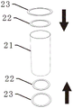
Fig. 2 is a schematic structural view of a water collecting well.
Fig. 3 is a schematic structural view of a pumping tube.
Fig. 4 is a schematic structural view of the exhaust pipe.
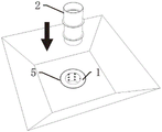
Fig. 5 is a construction structure view of a water filtering well and a filter screen.
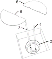
Fig. 6 is a schematic view of sump well installation.
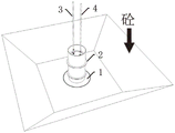
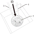
Fig. 7 is a diagram showing the installation effect of the exhaust pipe and the pumping pipe.
FIG. 8 is a schematic view of the installation of the well sealing base.
Fig. 9 is a schematic view of installation of the anti-floating reinforcing mesh.
Fig. 10 is a schematic diagram of a sump well plugging structure.
Fig. 11 is a diagram of the plugging effect of the water collecting well.
Wherein: 11-water filtering well upper cover plate, 12-water filtering well skeleton, 13-base, 2-water collecting well, 21-water collecting well barrel, 22-barrel inner water stopping ring, 23-barrel outer water stopping ring, 3-water pumping pipe, 32-water pumping pipe water stopping ring, 33-water pumping pipe orifice filtering device, 34-water pumping pipe gate valve, 35-water pumping pipe union, 4-air inlet pipe, 42-air inlet pipe water stopping ring, 43-air inlet pipe gate valve, 44-air inlet pipe union, 5-filter screen, 6-well sealing base, 7-anti-floating steel bar net piece and 8-plug.
Detailed Description
The structure and function of the present invention will be further explained with reference to the accompanying drawings.
As shown in fig. 1-11, the plugging device for water collecting well penetrating raft comprises a water filtering well 1, a water collecting well 2, a water pumping pipe 3, an air inlet pipe 4, a well sealing base 6, an anti-floating reinforcing steel mesh 7 and a plug 8, wherein the water filtering well 1 is embedded in the raft with larger water outlet at the bottom of a foundation bed, the water collecting well 2 is welded and installed on the water filtering well 1, main ribs of the raft are welded with the outside of the water collecting well and anchored in raft concrete, the water collecting well 2 comprises a water collecting well cylinder 21, an inner water stop ring plate 22 and an outer water stop ring plate 23 are respectively arranged inside and outside the water collecting well cylinder 21, the water pumping pipe 3 and the air inlet pipe 4 are positioned in the water collecting well 2, the well sealing base 6 is positioned at the upper part of the water collecting well, the anti-floating reinforcing steel mesh 7 is installed on the well sealing base 6 and welded with the side wall of the water collecting well, the water collecting well is sealed and plugged, and the upper end ports of the air inlet pipe 4 and the water pumping pipe 3 are plugged by the plug 8.
In order to prevent the residue soil from entering the water filtering well, a filter screen 5 is also arranged outside the water filtering well. The water filtering well 1 comprises a water filtering well upper cover plate 11, a water filtering well framework 12 and a base 13. The well sealing base 6 is two semicircular steel plates, and two notches are formed in the diameter of each steel plate for the water pumping pipe 3 and the air inlet pipe 4 to pass through. The water collecting well cylinder body is made of a 16mm thick steel plate, the diameter of the water collecting well cylinder body is 1500mm, and the height of the water collecting well cylinder body is equal to the thickness of the bottom plate. The width of the inner and outer water stop ring plates is 100mm, and the thickness of the inner and outer water stop ring plates is 10mm. An upper water pumping pipe water stop ring 32 is installed outside the water pumping pipe 3, a filtering device 33 is arranged at a pipe orifice at the lower end of the water pumping pipe 3, a movable joint 35 is arranged at a pipe orifice at the upper end of the water pumping pipe 3, and a water pumping pipe gate valve 34 is arranged below the movable joint 35 of the water pumping pipe. The air inlet pipe 4 is externally provided with an air inlet pipe water stop ring 42, an upper pipe opening of the air inlet pipe 4 is provided with an air inlet pipe union 44, and an air inlet pipe gate valve 43 is arranged below the air inlet pipe union 44.
The construction process for plugging the impervious water collecting well by the hidden type through raft plates comprises the following steps:
1) And according to the device drawing, the water filtering well 1, the water collecting well 2, the water pumping pipe 3, the air inlet pipe 4, the well sealing base 6 and the anti-floating reinforcing steel bar net piece 7 are manufactured and molded on the ground for standby.
2) After the foundation pit is excavated to the deepest part of the foundation, excavating a 1.5-meter deep pit downwards again, installing the water filtering well 1, enabling the upper opening of the water filtering well 1 to be flush with the deepest cushion layer of the basic raft plate, filling broken stones in the peripheral gap to serve as filtering materials, excavating part auxiliary drainage blind ditches, pumping water through a temporary submersible pump, and enabling underground water around the water filtering well to be discharged to the water filtering well 1 through gravity;
3) After the foundation raft bed course construction is completed, the temporary submersible pump stops pumping water, the water collecting well 2 is rapidly installed above the water filtering well 1, the upper opening of the water collecting well is flush with the concrete surface of the foundation raft bed, and the water pumping pump is placed into the water filtering well 1 from the water collecting well 2 to continuously pump and drain the underground water, so that the underground water level is always lower than the foundation pit raft bed course;
4) In the process of pumping water by the temporary water pump, basic raft steel bars are installed, and when upper and lower layers of raft steel bars are crossed with the plane of the water collecting well, the raft steel bars are bent and disassembled by 90 degrees and are firmly welded with the outer wall of the water collecting well;
5) Pouring raft plate concrete to be flush with the upper opening of the water collecting well 2, maintaining the concrete to reach the designed strength, and normally pumping underground water by using a temporary water pump;
6) Waiting for the completion of the structure of the building main body, and when the well sealing condition is reached, mounting the self-priming pump main body and the drain pipe on the raft plate;
7) Vertically installing a water pumping pipe 3 and an air inlet pipe 4 from the inside of a water collecting well 2, embedding the bottoms of the water pumping pipe 3 and the air inlet pipe 4 into the water filtering well 1, stopping pumping water by using a submersible pump, starting a self-priming pump to pump water, and taking out the submersible pump in the water collecting well;
8) In the process of keeping the self-priming pump to pump water, mounting two semicircular well sealing bases 6 at the lower part of a water collecting well, and enabling a water pumping pipe 3 and an air inlet pipe 4 to penetrate through two small holes in the well sealing bases;
9) In the process of keeping the self-priming pump to pump water, installing an anti-floating steel bar net piece 7, bending the net piece and the inner wall of the water collecting well at a confluence position by 90 degrees, and firmly welding;
10 In the process of pumping water by the self-sucking pump, concrete in the water collecting well is poured to the water pumping pipe gate valve 34 and the air inlet pipe gate valve 43 for the first time, and the concrete is maintained to reach the design strength;
11 When the self-priming pump stops pumping water, the pumping pipe gate valve 34 and the air inlet pipe gate valve 43 are closed, and pipelines above the pumping pipe union 35 and the air inlet pipe union 44 are dismantled;
12 And) pouring concrete in the pumping well for the second time to the designed elevation of the raft, covering the upper ports of the pumping pipes 3 and the air inlet pipes 4, and completing well sealing.
During construction, the water filtering well (1) is buried under the bottom of the foundation mat layer according to the water outlet condition of a construction site and used for collecting underground water gushing in a centralized mode, and the filter screen (5) outside the water filtering well (1) can effectively filter broken slag and avoid blocking a water pumping pipe. The top of the water filtering well 1 is provided with a water collecting well 2, and the two parts are welded and connected. The sump pit barrel is installed above the raft plate bedding bottom, and within the anchor raft plate concrete, the height is the same as raft plate thickness, and the inside and outside both sides of barrel respectively set up twice seal ring from top to bottom. The raft main ribs are bent by 90 degrees and are welded with the outer wall of the water collecting well cylinder body, so that the raft main ribs form a whole body to prevent the cylinder body from floating upwards. Suction pipe 3 and intake pipe 4 are located 2 interior pump drainage foundation ditch bottoms of sump pit and gush water, and the water pumper water inlet is connected with 3 last ports of suction pipe, and the delivery port connects to ground water lifting pipe, outside the direct discharge hole of suction pipe in the water catch bowl, for convenient pumping pipe shutoff groundwater behind the sealed ground well and demolish pipeline more than the well head, 300mm sets up the loose joint under the raft roof, and the loose joint has the valve.
After the pumping and drainage work is finished, the well sealing base 6 is located on the lower portion of the water collecting well and welded with the pumping well to serve as a bottom sealing template, the anti-floating reinforcing steel mesh 7 is installed above the well sealing base 6 in a bending mode and welded with the inner wall of the pumping well, and the pumping well, the pumping pipe and the space between the pumping pipe and the drainage pipe are poured for plugging. Finally, after the strength of the plugging concrete is reached, the valve 43 is closed to cut off the water source, the pipeline on the upper part of the movable joint 44 is dismantled, and the air inlet pipe 4 and the upper port of the water pumping pipe 3 are plugged by the plug 8.
According to the invention, a water collecting well penetrates through a raft plate and is welded on a main rib of the raft plate, a water pumping pipe and an exhaust pipe are arranged in the water collecting well, water is pumped and drained normally before well sealing, concrete is adopted to pour the space between the water collecting well and the water pumping pipe and the exhaust pipe in a normal water pumping state during well sealing, after strength generated by concrete solidification can resist underground water pressure, valves on the water pumping pipe and the air inlet pipe are closed, the upper water pumping pipe and the upper air inlet pipe are removed from a movable joint position, the water pumping pipe and the upper air inlet pipe are tightly sealed by using a plug, and concrete at the valve position is poured to complete well sealing.
The invention solves the construction problem under the serious condition of building foundation pit water inrush, and ensures that the building construction is not influenced by underground water inrush. Meanwhile, the construction is made of local materials, each process is easy to operate, and the effect is direct. The problem that underground pumping and drainage difficulty during severe foundation pit construction in gushing water causes building foundation construction failure or causes quality problems is solved through the device, and the problem that well sealing is difficult or poor in well sealing quality and water leakage is easy to achieve through a traditional process is solved. The device reduces the difficulty of foundation pit drainage construction, greatly shortens the construction time of the bottom plate, ensures the construction quality and saves the construction and construction cost. The device is hidden, and does not influence the original design function of the building after the well is sealed. The underground water drainage in the pit effectively prevents the influence on the underground water outside the waterproof enclosure of the foundation pit, and ensures the safety of surrounding buildings and environment. The problem of plugging of the water pumping pipe is avoided by adding the filter screen and the filter device arranged on the lower part of the water pumping pipe.
Claims (6)
1. The utility model provides a construction process that impervious sump pit can be shutoff to hidden type crossing raft board which characterized in that: the hidden type impermeable water collecting well penetrating through the raft plate can be plugged, and comprises a water filtering well (1), a water collecting well (2), a water pumping pipe (3), an air inlet pipe (4), a well plugging base (6), an anti-floating reinforcing steel bar mesh (7) and a plug (8), wherein the water filtering well (1) is embedded in the raft plate with larger water outlet at the bottom of a foundation bed course, the diameter of the water filtering well (1) is larger than that of the water collecting well (2), the water collecting well (2) is welded on the water filtering well (1), main ribs of the raft plate are welded with the outside of the water collecting well and anchored in raft plate concrete, the water collecting well (2) comprises a water collecting well cylinder (21), an inner water stopping ring plate (22) and an outer water stopping ring plate (23) are respectively arranged inside and outside the water collecting well cylinder (21), the water pumping pipe (3) and the water plugging pipe (4) are positioned in the water collecting well (2), the well plugging base (6) is positioned at the bottom of the water collecting well (2), the anti-floating reinforcing steel bar mesh (7) is arranged above the well plugging base (6) and welded with the side wall of the water collecting well, and the water pumping pipe (4) and the plug are plugged;
an upper water pumping pipe water stop ring (32) is installed outside the water pumping pipe (3), a filtering device (33) is arranged at the pipe orifice at the lower end of the water pumping pipe (3), a movable joint (35) is arranged at the pipe orifice at the upper end of the water pumping pipe (3), and a water pumping pipe gate valve (34) is arranged below the water pumping pipe movable joint (35);
an air inlet pipe water stop ring (42) is installed outside the air inlet pipe (4), an air inlet pipe union (44) is arranged at the pipe orifice at the upper end of the air inlet pipe (4), and an air inlet pipe gate valve (43) is arranged below the air inlet pipe union (44);
the construction process steps of the hidden type penetrating raft capable of plugging the anti-seepage water collecting well are as follows:
1), manufacturing and molding a water filtering well (1), a water collecting well (2), a water pumping pipe (3), an air inlet pipe (4), a well sealing base (6) and an anti-floating steel bar net piece (7) on the ground for later use according to a device drawing;
2) After the foundation pit is excavated to the deepest part of the foundation, a 1.5-meter deep pit is excavated downwards again, the water filtering well (1) is installed, the upper opening of the water filtering well (1) is flush with the deepest cushion layer of the foundation raft plate, broken stones are filled in the peripheral gap to serve as filtering materials, an auxiliary drainage blind ditch is excavated, water is pumped through a temporary submersible pump, and underground water around the water filtering well is drained to the water filtering well (1) through gravity;
3) After the foundation raft bed course construction is completed, the temporary submersible pump stops pumping water, the water collecting well (2) is rapidly installed above the water filtering well (1), the upper opening of the water collecting well is flush with the concrete surface of the foundation raft bed course, and the water pump is placed into the water filtering well (1) from the water collecting well (2) to continuously pump and drain the underground water, so that the underground water level is always lower than the foundation pit raft bed course;
4) In the process of pumping water by the temporary water pump, basic raft steel bars are installed, and when upper and lower layers of raft steel bars are crossed with the plane of the water collecting well, the raft steel bars are bent and disassembled by 90 degrees and are firmly welded with the outer wall of the water collecting well;
5) Pouring raft plate concrete to be flush with the upper opening of the water collecting well (2), maintaining the concrete to reach the designed strength, and normally pumping and draining the underground water by a temporary water pump;
6) Waiting for the completion of the structure of the building main body, and when the well sealing condition is reached, mounting the self-priming pump main body and the drain pipe on the raft plate;
7) Vertically installing a water pumping pipe (3) and an air inlet pipe (4) from the inside of a water collecting well (2), embedding the bottoms of the water pumping pipe (3) and the air inlet pipe (4) into the water filtering well (1), stopping pumping water by using a submersible pump, starting a self-priming pump to pump water, and taking out the submersible pump in the water collecting well;
8) In the process of keeping the self-sucking pump to suck water, mounting two semicircular well sealing bases (6) at the lower part of a water collecting well, and enabling a water suction pipe (3) and an air inlet pipe (4) to penetrate through two small holes in the well sealing bases;
9) In the process of keeping the self-priming pump to pump water, an anti-floating steel bar net piece (7) is installed, and the joint of the net piece and the inner wall of the water collecting well is bent by 90 degrees and is firmly welded;
10 In the process of keeping the self-sucking pump to pump water, concrete in the water collecting well is poured to a water pumping pipe gate valve (34) and an air inlet pipe gate valve (43) for the first time, and the concrete is maintained to reach the design strength;
11 Stopping pumping water by the self-priming pump, closing a pumping pipe gate valve (34) and an air inlet pipe gate valve (43), and dismantling pipelines above a pumping pipe union (35) and an air inlet pipe union (44);
12 And) pouring concrete in the pumping well for the second time to design the elevation of the raft, and covering the upper ports of the pumping pipes (3) and the air inlet pipes (4) to finish well sealing.
2. The construction process of the hidden through raft capable of plugging the anti-seepage water collecting well according to claim 1, characterized in that: a filter screen (5) is also arranged outside the water filtering well (1).
3. The construction process of the hidden through raft capable of plugging the anti-seepage water collecting well according to claim 1, characterized in that: the water filtering well (1) comprises a water filtering well upper cover plate (11), a water filtering well framework (12) and a base.
4. The construction process of the hidden type through raft capable of plugging the impervious water collecting well according to claim 1, is characterized in that: the well sealing base (6) is two semicircular steel plates, two notches are formed in the diameter of each steel plate, and the water pumping pipe (3) and the air inlet pipe (4) can pass through the notches.
5. The construction process of the hidden through raft capable of plugging the anti-seepage water collecting well according to claim 1, characterized in that: the water collecting well cylinder body (21) is made of a 16mm thick steel plate, the diameter of the water collecting well cylinder body is 1500mm, and the height of the water collecting well cylinder body is equal to the thickness of the bottom plate.
6. The construction process of the hidden through raft capable of plugging the anti-seepage water collecting well according to claim 1, characterized in that: the width of the inner water stop ring plate (22) is 100mm, and the thickness of the inner water stop ring plate is 10mm.
Priority Applications (1)
| Application Number | Priority Date | Filing Date | Title |
|---|---|---|---|
| CN201710714179.0A CN107326918B (en) | 2017-08-18 | 2017-08-18 | Hidden type plugging impervious water collecting well penetrating through raft plates and construction process thereof |
Applications Claiming Priority (1)
| Application Number | Priority Date | Filing Date | Title |
|---|---|---|---|
| CN201710714179.0A CN107326918B (en) | 2017-08-18 | 2017-08-18 | Hidden type plugging impervious water collecting well penetrating through raft plates and construction process thereof |
Publications (2)
| Publication Number | Publication Date |
|---|---|
| CN107326918A CN107326918A (en) | 2017-11-07 |
| CN107326918B true CN107326918B (en) | 2022-12-09 |
Family
ID=60227976
Family Applications (1)
| Application Number | Title | Priority Date | Filing Date |
|---|---|---|---|
| CN201710714179.0A Active CN107326918B (en) | 2017-08-18 | 2017-08-18 | Hidden type plugging impervious water collecting well penetrating through raft plates and construction process thereof |
Country Status (1)
| Country | Link |
|---|---|
| CN (1) | CN107326918B (en) |
Families Citing this family (6)
| Publication number | Priority date | Publication date | Assignee | Title |
|---|---|---|---|---|
| CN108425372A (en) * | 2018-05-03 | 2018-08-21 | 中国建筑第二工程局有限公司 | A kind of protective device and foundation pit shut-in well method for the uninterrupted precipitation in foundation pit part |
| CN110144917B (en) * | 2019-05-16 | 2024-02-20 | 中国水利水电第五工程局有限公司 | Portable reverse filtering device for bad geology and use method thereof |
| CN113982007A (en) * | 2021-08-12 | 2022-01-28 | 中建四局第五建筑工程有限公司 | Enclosed construction behind sump pit is reserved in basement bottom plate post-cast strip |
| CN115125976B (en) * | 2022-07-11 | 2023-05-16 | 河南大学 | Civil engineering foundation pit drainage structure and construction method thereof |
| CN115247426A (en) * | 2022-09-08 | 2022-10-28 | 中建八局第二建设有限公司 | Pipe well dewatering device capable of reducing water seepage of bottom plate and well sealing construction method |
| CN116837906A (en) * | 2023-07-04 | 2023-10-03 | 上海宝冶集团有限公司 | Water burst blocking method for pile head of prefabricated pipe pile |
Family Cites Families (7)
| Publication number | Priority date | Publication date | Assignee | Title |
|---|---|---|---|---|
| JP4275437B2 (en) * | 2003-03-20 | 2009-06-10 | 株式会社フジタ | Structure for suppressing buoyancy of structures |
| CN103898915B (en) * | 2014-04-18 | 2016-02-10 | 中国二十二冶集团有限公司 | Building small-area deep foundation pit anti-floating water stop construction method |
| CN103967028A (en) * | 2014-05-27 | 2014-08-06 | 江苏南通三建集团有限公司 | Immersed tube drainage structure and method for handling suddenly-produced foundation pit water bursting and fountains through immersed tube drainage structure |
| CN204266590U (en) * | 2014-11-19 | 2015-04-15 | 大同泰瑞集团建设有限公司 | Sump, hoistway formwork bed die anti-floating system |
| CN204530733U (en) * | 2015-03-08 | 2015-08-05 | 青岛一建集团有限公司 | Underground construction deep-well precipitation well head plugging structure |
| CN106320353B (en) * | 2016-07-18 | 2019-07-23 | 中天建设集团有限公司 | A kind of construction method of basement construction Yield rainfall relation device |
| CN207193994U (en) * | 2017-08-18 | 2018-04-06 | 云南省建设投资控股集团有限公司 | A kind of concealed type, which passes through raft plate, can block impervious sump |
-
2017
- 2017-08-18 CN CN201710714179.0A patent/CN107326918B/en active Active
Also Published As
| Publication number | Publication date |
|---|---|
| CN107326918A (en) | 2017-11-07 |
Similar Documents
| Publication | Publication Date | Title |
|---|---|---|
| CN107326918B (en) | Hidden type plugging impervious water collecting well penetrating through raft plates and construction process thereof | |
| CN102797266B (en) | Well sealing waterproof construction method for dewatering well | |
| CN109736340B (en) | Dewatering device and method for guaranteeing integrity of cushion layer by reserving dewatering well on foundation slab | |
| CN109519150B (en) | Dewatering well plugging device and method for large water yield | |
| CN206346209U (en) | A kind of quick solution dewatering well piping plugging structure | |
| CN110219313B (en) | Drainage system and construction method for underground construction blind well | |
| CN207193996U (en) | A kind of precipitation pipe well well-sealing device | |
| CN212200475U (en) | High water level area precipitation well shutoff structure | |
| CN109723071B (en) | Construction method of double-layer steel drum drainage system built in basement floor post-cast strip | |
| CN105484277A (en) | Component for tubular well precipitation construction in elevator foundation pit or sump and construction method | |
| CN105780792B (en) | A kind of foundation pit high water head Dewatering by pressure reduction well shut-in well method and structure of shunting in a well | |
| CN212641468U (en) | Pit-in-pit rapid construction structure | |
| CN212506349U (en) | Water-logging well sealing device for water-lowering zone of ultra-deep foundation pit pipe well | |
| CN212129150U (en) | Deep basal pit precipitation well block structure | |
| CN210712963U (en) | Drainage structure of basement bottom plate post-cast strip | |
| CN205205844U (en) | Member is used in construction of tubular well precipitation in elevator foundation ditch or sump pit | |
| CN206829163U (en) | A kind of high artesian section construction Yield rainfall relation device | |
| CN212200511U (en) | Deep foundation pit plugging device | |
| CN207193994U (en) | A kind of concealed type, which passes through raft plate, can block impervious sump | |
| CN210684746U (en) | Modified precipitation well plugging device | |
| CN208441115U (en) | A kind of diaphram wall piping plugging structure | |
| CN110258660A (en) | The manufacture craft and shut-in well technique of the decompression drainage sump of basement anti-floating | |
| CN204491643U (en) | The constructing structure that on a kind of raft plate, dewatering well is closed | |
| CN220598488U (en) | Plugging device for deep well of building engineering after lowering underground water level | |
| CN113216123B (en) | Gate chamber side wall karst water gushing treatment method |
Legal Events
| Date | Code | Title | Description |
|---|---|---|---|
| PB01 | Publication | ||
| PB01 | Publication | ||
| SE01 | Entry into force of request for substantive examination | ||
| SE01 | Entry into force of request for substantive examination | ||
| GR01 | Patent grant | ||
| GR01 | Patent grant |