CN107278343B - Radar antenna and suitable method for influencing the radiation characteristics of a radar antenna - Google Patents
Radar antenna and suitable method for influencing the radiation characteristics of a radar antenna Download PDFInfo
- Publication number
- CN107278343B CN107278343B CN201580066071.4A CN201580066071A CN107278343B CN 107278343 B CN107278343 B CN 107278343B CN 201580066071 A CN201580066071 A CN 201580066071A CN 107278343 B CN107278343 B CN 107278343B
- Authority
- CN
- China
- Prior art keywords
- antenna
- transmitting
- parasitic element
- radar
- parasitic
- Prior art date
- Legal status (The legal status is an assumption and is not a legal conclusion. Google has not performed a legal analysis and makes no representation as to the accuracy of the status listed.)
- Active
Links
Images

Classifications
-
- H—ELECTRICITY
- H01—ELECTRIC ELEMENTS
- H01Q—ANTENNAS, i.e. RADIO AERIALS
- H01Q19/00—Combinations of primary active antenna elements and units with secondary devices, e.g. with quasi-optical devices, for giving the antenna a desired directional characteristic
- H01Q19/10—Combinations of primary active antenna elements and units with secondary devices, e.g. with quasi-optical devices, for giving the antenna a desired directional characteristic using reflecting surfaces
-
- H—ELECTRICITY
- H01—ELECTRIC ELEMENTS
- H01Q—ANTENNAS, i.e. RADIO AERIALS
- H01Q21/00—Antenna arrays or systems
- H01Q21/06—Arrays of individually energised antenna units similarly polarised and spaced apart
- H01Q21/08—Arrays of individually energised antenna units similarly polarised and spaced apart the units being spaced along or adjacent to a rectilinear path
-
- H—ELECTRICITY
- H01—ELECTRIC ELEMENTS
- H01Q—ANTENNAS, i.e. RADIO AERIALS
- H01Q15/00—Devices for reflection, refraction, diffraction or polarisation of waves radiated from an antenna, e.g. quasi-optical devices
- H01Q15/14—Reflecting surfaces; Equivalent structures
- H01Q15/148—Reflecting surfaces; Equivalent structures with means for varying the reflecting properties
-
- H—ELECTRICITY
- H01—ELECTRIC ELEMENTS
- H01Q—ANTENNAS, i.e. RADIO AERIALS
- H01Q19/00—Combinations of primary active antenna elements and units with secondary devices, e.g. with quasi-optical devices, for giving the antenna a desired directional characteristic
- H01Q19/005—Patch antenna using one or more coplanar parasitic elements
-
- H—ELECTRICITY
- H01—ELECTRIC ELEMENTS
- H01Q—ANTENNAS, i.e. RADIO AERIALS
- H01Q9/00—Electrically-short antennas having dimensions not more than twice the operating wavelength and consisting of conductive active radiating elements
- H01Q9/04—Resonant antennas
- H01Q9/0407—Substantially flat resonant element parallel to ground plane, e.g. patch antenna
-
- G—PHYSICS
- G01—MEASURING; TESTING
- G01S—RADIO DIRECTION-FINDING; RADIO NAVIGATION; DETERMINING DISTANCE OR VELOCITY BY USE OF RADIO WAVES; LOCATING OR PRESENCE-DETECTING BY USE OF THE REFLECTION OR RERADIATION OF RADIO WAVES; ANALOGOUS ARRANGEMENTS USING OTHER WAVES
- G01S13/00—Systems using the reflection or reradiation of radio waves, e.g. radar systems; Analogous systems using reflection or reradiation of waves whose nature or wavelength is irrelevant or unspecified
- G01S13/02—Systems using reflection of radio waves, e.g. primary radar systems; Analogous systems
- G01S2013/0236—Special technical features
- G01S2013/0245—Radar with phased array antenna
-
- H—ELECTRICITY
- H01—ELECTRIC ELEMENTS
- H01Q—ANTENNAS, i.e. RADIO AERIALS
- H01Q1/00—Details of, or arrangements associated with, antennas
- H01Q1/42—Housings not intimately mechanically associated with radiating elements, e.g. radome
-
- H—ELECTRICITY
- H01—ELECTRIC ELEMENTS
- H01Q—ANTENNAS, i.e. RADIO AERIALS
- H01Q21/00—Antenna arrays or systems
- H01Q21/06—Arrays of individually energised antenna units similarly polarised and spaced apart
- H01Q21/061—Two dimensional planar arrays
Abstract
A radar antenna is described having a parasitic element for influencing the radiation characteristic of the radar antenna, wherein the radiation characteristic of the radar antenna is expressed by the spatial arrangement of the parasitic element relative to the radar antenna and the phase angle value of the radiated energy ) Is associated with a radar antenna and parasitic elements, and the radar antenna is implemented in microstrip technology.
Description
Technical Field
The present invention relates to a radar antenna and a suitable method for influencing the radiation characteristics of a radar antenna.
Background
It is generally known that the radiation characteristic of radar antennas takes place substantially spherically, the individual directional elements not being to influence the radiation characteristic. However, the radiation characteristic is primarily (vorranging) spherically even in the case of the directional element used, whose illumination is insufficient if necessary in the edge region.
Disclosure of Invention
The object of the present invention is therefore to develop a radar antenna and a suitable method for this purpose, which avoids the above-mentioned disadvantages. The object of the invention is to improve or influence the radiation characteristics of a radar antenna.
The task is solved with the features of claims 1 and 15.
If the radiation characteristic of the antenna is related to the antenna and the parasitic element by the spatial arrangement of the parasitic element relative to the antenna and the phase angle value of the radiated energy according to the present application, an improved radiation characteristic can be brought about via the parasitic element, which produces a signal effect in particular in the unreachable edge region.
In the case of radar antennas using microstrip technology (mikrostreifeftechnolie), it is possible to develop and construct the device according to the present application, preferably in a minimized shape. With microstrip technology it is thus possible, taking into account the physical facts, to provide radiation characteristics in the case of radar antennas that can be influenced by parasitic elements.
Further advantageous configurations of the invention are the subject matter of the dependent claims.
With the arrangement of parasitic elements, on the one hand, an expansion of the radiation characteristic of the radar antenna can be brought about above all in terms of its orientation, but also a focusing of the radiation characteristic of the radar antenna. Advantageously, an improved radiation characteristic can be used even in the case of one antenna array or even in the case of a plurality of antenna arrays (antenna arrays) implemented primarily in microstrip line technology. Likewise, it has proven to be advantageous if the parasitic element is also formed by one or more antenna arrays implemented in microstrip technology.
It has likewise proved to be advantageous if the parasitic elements change their radiation characteristics by mutual coupling with one another and/or by mutual coupling with the antenna to be influenced. In this way, the desired radiation characteristics can be simply induced and oriented as a function of the application profile (anwendoungspprofile). If the parasitic element is arranged parallel to the longitudinal axis of the radar antenna to be affected, a more optimized radiation characteristic is given.
If the parasitic element at the antenna mount has a defined termination (abschalss), a preferred influence on the radiation characteristics of the radar antenna can be achieved and implemented.
If the radar antenna and/or the parasitic element is covered with a radome, the radiation characteristics of the radar antenna can likewise be influenced by using the geometry of the radome, and in particular a coupling such as described in claim 6 is additionally brought about. The radiation characteristics of the radar antenna are thus influenced via the radome, in addition to the parasitic elements, or as the case may be, to the edge region or edge regions.
It has proved to be advantageous if the radar antenna with parasitic element is applied in a frequency range between 1 MHz and 200 GHz, preferably in a frequency range between 20 GHz and 100 GHz. The frequency range is particularly effectively implemented in interaction with microstrip lines. A particularly emphasized use of antennas with parasitic elements lies in the frequency range between 70 and 80 GHz. It has likewise proved to be advantageous if an antenna consisting of a transmitter or a receiver or a combined transmitter-receiver radar antenna is used. The radar system according to the present application shows that an advantageous field of application is the use in determining the position and/or velocity of an object, i.e. the influence and orientation of radiation properties.
Further advantageous configurations of the invention are the subject matter of the other dependent claims.
Drawings
An advantageous configuration of the invention is shown in accordance with the following figures, in which:
fig. 1 shows a radar antenna system according to the present application in microstrip line technology.
Fig. 2 shows a radar antenna system according to the present application with multiple antenna arrays in microstrip line technology.
Fig. 3 shows the radiation characteristics of a radar antenna system according to the present application.
Fig. 4 shows the energy distribution within a radar antenna system according to the present application.
Detailed Description
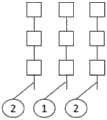
An antenna array (antenna array) to be influenced in microstrip technology, which preferably has parasitic elements 2 arranged in parallel, is denoted by 1 in fig. 1, which parasitic elements 2 are likewise shown as antenna array in microstrip technology.
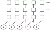
A further advantageous embodiment consists in using a plurality of antenna lines to be influenced in microstrip line technology according to fig. 2, which are influenced by parasitic elements 2, wherein parasitic elements 2 are arranged in parallel in double as antenna lines in microstrip technology. In this connection, it should be emphasized that depending on the number of parasitic elements arranged in parallel, the radiation characteristics can be influenced accordingly for the radar antenna system according to the present application.
Fig. 3 shows how far (swiwiieit) the radiation characteristic of the radar antenna 1 of fig. 1 can lead to improved illumination, in particular in the edge region (randzonnbereich), in the radar antenna system according to the present application. The radiation characteristic corresponding to the azimuth angle Θ is reproduced as well in fig. 3, which reproduces an extended (aufgeeweite) radiation characteristic with a corresponding antenna gain 3.
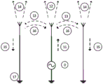
A qualitative description of the effect on the radiation characteristics by the mutual coupling between the transmitting antenna and the two parasitic elements according to the diagram of fig. 1 is reproduced in fig. 4. Energy propagates from signal source 0 toward the radar antenna, which functions as a transmitting antenna. Energy is then radiated from the transmit antenna into space. A portion of the energy impinges on the parasitic element. A portion of the energy is reflected by the parasitic element and radiated into space. The radiated energy has a phase angle value phi 1. The parasitic element receives the energy radiated from the transmitting antenna towards the parasitic antenna according to 13. The following procedure is described with 14, in which energy is reflected by the parasitic element 2 and radiated into space by the radar antenna. The energy has a phase angle value phi 2. The energy received by the parasitic element is denoted by 15. The energy reflected by the parasitic element 2 towards the transmitting antenna 1 is denoted by 16. Thus, the radiation characteristics of the transmitting antenna 1 are affected by the radiated energy of the parasitic element. The superposition of the radiated energy of the transmitting antenna 1 and the radiated energy of the parasitic element 2 occurs. Whether the radiation characteristic is expanded or focused is related to the spatial arrangement of the respective transmitting or parasitic antenna and the respective phase angle values phi 1, phi 2, etc.
In this way, a radar antenna system is provided which can expand the radiation characteristics as required and can be used advantageously, in particular, in the case of microstrip line technology.
Claims (12)
1. A radar antenna, comprising:
-a transmitting or receiving antenna (1), the transmitting or receiving antenna (1) comprising three or more microstrip antenna lines, each microstrip antenna line of the transmitting or receiving antenna (1) comprising a plurality of electrically connected patches arranged in a row extending in a first direction;
a pair of parasitic elements (2), each parasitic element (2) comprising a microstrip antenna array, each microstrip antenna array of the parasitic elements (2) comprising a plurality of electrically coupled patches arranged in a row extending in the first direction,
wherein the pair of parasitic elements (2) is configured to influence a radiation characteristic of the radar antenna, the radiation characteristic of the radar antenna being related to:
the spatial position of the pair of parasitic elements (2) relative to the transmitting or receiving antenna (1),
a first phase angle value of the energy radiated by the transmitting or receiving antenna (1) ,
,
A second phase angle value of radiated energy of a first parasitic element of the pair of parasitic elements (2) And (b)
The second parasitic element (2) of the pair being radiated byThird phase angle value of energy of the radiation ,
,
Wherein:
the spatial position of the pair of parasitic elements (2) relative to the transmitting or receiving antenna (1) azimuthally causes an expansion of the radiation characteristics of the radar antenna,
the microstrip antenna lines of the pair of parasitic elements (2) are arranged adjacent and parallel to each other and the microstrip antenna lines of the transmitting or receiving antenna (1) are arranged adjacent and parallel to each other, wherein a first microstrip antenna line of the transmitting or receiving antenna (1) and a second microstrip antenna line of the transmitting or receiving antenna (1) are arranged on opposite sides of a third microstrip antenna line of the transmitting or receiving antenna (1), wherein the microstrip antenna line of the parasitic element (2) is arranged on a side of the transmitting or receiving antenna (1) opposite to the side of the third microstrip antenna line facing the transmitting or receiving antenna (1).
2. Radar antenna according to claim 1, wherein the pair of parasitic elements (2) change the radiation characteristic of the radar antenna by expanding the radiation characteristic in azimuth direction by mutual coupling between the first parasitic element and the second parasitic element and/or by mutual coupling between the pair of parasitic elements (2) and the transmitting or receiving antenna (1).
3. Radar antenna according to one of the preceding claims, wherein the first direction corresponds to a longitudinal axis of the radar antenna to be affected.
4. Radar antenna according to one of the preceding claims, wherein the microstrip antenna array of the pair of parasitic elements (2) ends at the radar antenna mount in the first direction.
5. Radar antenna according to one of the preceding claims, wherein the radar antenna is configured to operate in a frequency range between 1 MHz and 200 GHz.
6. Radar antenna according to one of the preceding claims, wherein the radar antenna is configured to operate in a frequency range between 70 and 80 GHz.
7. Radar antenna according to one of the preceding claims, wherein the radar antenna is configured to be used as a transmitter, a receiver antenna or a combined transmitter-receiver antenna.
8. Radar antenna according to one of the preceding claims, wherein the radar antenna is part of a radar system for position and/or velocity determination of an object.
9. Radar antenna according to claim 1, wherein the pair of parasitic elements (2) comprises shorted line ends.
10. Radar antenna according to claim 1, wherein the spatial position of the pair of parasitic elements (2) with respect to the transmitting or receiving antenna (1) causes a focusing of the radiation characteristic of the radar antenna in azimuth direction.
11. Radar system comprising a radar antenna according to at least one of the preceding claims.
12. A method for affecting a radiation characteristic of a radar antenna using a first parasitic element and a second parasitic element, the method comprising the steps of:
a) Propagating (11) energy from a signal source (0) to a transmitting or receiving antenna (1);
b) Radiating (12) said energy from said transmitting or receiving antenna (1) to spaceWherein the radiated energy has a phase angle value Wherein a portion of the energy radiated from the transmitting or receiving antenna (1) impinges on the first parasitic element and the second parasitic element;
c) A portion of the energy impinging on the first parasitic element is reflected (16) from the first parasitic element and a portion of the energy reflected (14) from the first parasitic element is radiated (16) into the space, wherein the radiated energy reflected from the first parasitic element has a phase angle value ;
;
d) A portion of the energy impinging on the second parasitic element is reflected (16) from the second parasitic element and a portion of the energy reflected (14) from the second parasitic element is radiated (16) into the space, wherein the radiated energy reflected from the second parasitic element has a phase angle value ;
;
e) -receiving (15) by said first and second parasitic elements a portion of the energy radiated by said transmitting or receiving antenna (1) that strikes said first and second parasitic elements; and
f) Reflecting a portion of the energy from the first parasitic element and the second parasitic element back to the transmitting or receiving antenna (1);
wherein:
the spatial position of the first parasitic element and the second parasitic element relative to the transmitting or receiving antenna (1) azimuthally causes an expansion of the radiation characteristic of the radar antenna, and
the transmitting or receiving antenna (1) comprises three microstrip antenna lines, each microstrip antenna line of the transmitting or receiving antenna (1) comprising a plurality of electrically connected patches, the patches being arranged along a row extending in a first direction, and each parasitic element (2) comprising a microstrip antenna line, wherein each microstrip antenna line of the parasitic element (2) comprises a plurality of electrically coupled patches, the patches being arranged in a row extending in the first direction, and the microstrip antenna lines being arranged adjacent and parallel to each other, and the microstrip antenna lines of the transmitting or receiving antenna (1) being arranged adjacent and parallel to each other, wherein a first microstrip antenna line of the transmitting or receiving antenna (1) and a second microstrip antenna line of the transmitting or receiving antenna (1) are arranged on opposite sides of a third microstrip antenna of the transmitting or receiving antenna (1), wherein the microstrip antenna of the parasitic element (2) is arranged on the opposite side of the transmitting or receiving antenna (1) to the side facing the third microstrip antenna of the transmitting or receiving antenna (1), the parasitic element (2) being affected by the amount of radiation from the microstrip antenna (1).
Applications Claiming Priority (3)
| Application Number | Priority Date | Filing Date | Title |
|---|---|---|---|
| DE102014118036.4A DE102014118036A1 (en) | 2014-12-05 | 2014-12-05 | Radar antenna and suitable method for influencing the radiation characteristic of a radar antenna |
| DE102014118036.4 | 2014-12-05 | ||
| PCT/EP2015/078853 WO2016087676A1 (en) | 2014-12-05 | 2015-12-07 | Radar antenna and suitable method for influencing the radiation characteristics of a radar antenna |
Publications (2)
| Publication Number | Publication Date |
|---|---|
| CN107278343A CN107278343A (en) | 2017-10-20 |
| CN107278343B true CN107278343B (en) | 2023-04-28 |
Family
ID=55072605
Family Applications (1)
| Application Number | Title | Priority Date | Filing Date |
|---|---|---|---|
| CN201580066071.4A Active CN107278343B (en) | 2014-12-05 | 2015-12-07 | Radar antenna and suitable method for influencing the radiation characteristics of a radar antenna |
Country Status (7)
| Country | Link |
|---|---|
| US (1) | US11245198B2 (en) |
| EP (1) | EP3227961A1 (en) |
| JP (1) | JP6600686B2 (en) |
| KR (1) | KR102409534B1 (en) |
| CN (1) | CN107278343B (en) |
| DE (1) | DE102014118036A1 (en) |
| WO (1) | WO2016087676A1 (en) |
Families Citing this family (6)
| Publication number | Priority date | Publication date | Assignee | Title |
|---|---|---|---|---|
| TWM531066U (en) * | 2016-05-10 | 2016-10-21 | 道安達股份有限公司 | Antenna unit with wide beam |
| JP6896058B2 (en) * | 2017-03-09 | 2021-06-30 | 古河電気工業株式会社 | Radar device and target position detection method for radar device |
| CN110098468A (en) * | 2019-04-09 | 2019-08-06 | 惠州市德赛西威智能交通技术研究院有限公司 | Three hair four of one kind receives broad beam antenna |
| CN110265769A (en) * | 2019-07-01 | 2019-09-20 | 赵平 | A kind of microstrip antenna going edge effect and series feed microstrip antenna array |
| KR102186306B1 (en) | 2019-10-25 | 2020-12-03 | 세종대학교산학협력단 | Method and apparatus for analyzing radiation pattern of antenna |
| US11539139B1 (en) * | 2019-10-30 | 2022-12-27 | Ainstein Ai, Inc. | Wideband millimeter-wave microstrip antenna having impedance stabilizing elements and antenna array employing same |
Citations (7)
| Publication number | Priority date | Publication date | Assignee | Title |
|---|---|---|---|---|
| KR20020061717A (en) * | 2001-01-17 | 2002-07-25 | 정보통신연구진흥원 | Microstrip beam forming antenna |
| WO2012041567A1 (en) * | 2010-09-27 | 2012-04-05 | Robert Bosch Gmbh | Antenna system for radar sensors |
| CN102893451A (en) * | 2010-05-10 | 2013-01-23 | 法雷奥开关和传感器有限责任公司 | Driver assistance device for a vehicle, vehicle and method for operating a radar unit |
| KR20130137529A (en) * | 2012-05-29 | 2013-12-17 | 삼성전자주식회사 | Circularly polarized patch antennas, antenna arrays and devices including such antennas and arrays |
| WO2013190369A2 (en) * | 2012-06-22 | 2013-12-27 | Adant Technologies, Inc. | A reconfigurable antenna system |
| CN103907242A (en) * | 2011-10-15 | 2014-07-02 | 大众汽车有限公司 | Radar system for a road vehicle with improved calibrating possibilities |
| WO2014122902A1 (en) * | 2013-02-07 | 2014-08-14 | パナソニック株式会社 | Antenna device and wireless transmission device |
Family Cites Families (23)
| Publication number | Priority date | Publication date | Assignee | Title |
|---|---|---|---|---|
| DE6902510U (en) | 1969-01-22 | 1969-05-29 | Karlheinz Ing Schulz | BOILER FLUE PIPE CONNECTING ELEMENT |
| US5629713A (en) * | 1995-05-17 | 1997-05-13 | Allen Telecom Group, Inc. | Horizontally polarized antenna array having extended E-plane beam width and method for accomplishing beam width extension |
| JP2806350B2 (en) | 1996-03-14 | 1998-09-30 | 日本電気株式会社 | Patch type array antenna device |
| JP2000508144A (en) * | 1996-04-03 | 2000-06-27 | グランホルム,ヨハン | Dual polarization antenna array with ultra-low cross polarization and low side lobe |
| JP2001522578A (en) * | 1998-02-27 | 2001-11-13 | コーニンクレッカ フィリップス エレクトロニクス エヌ ヴィ | Antenna gain diversity |
| US6317100B1 (en) * | 1999-07-12 | 2001-11-13 | Metawave Communications Corporation | Planar antenna array with parasitic elements providing multiple beams of varying widths |
| JP2001111335A (en) | 1999-10-08 | 2001-04-20 | Toyota Central Res & Dev Lab Inc | Microstrip array antenna |
| ES2341185T3 (en) | 2001-10-19 | 2010-06-16 | Bea S.A. | METHOD OF DETECTION OF MOVEMENT AROUND AUTOMATIC DOORS. |
| WO2006035881A1 (en) * | 2004-09-30 | 2006-04-06 | Toto Ltd. | Microstrip antenna and high frequency sensor using microstrip antenna |
| JP2007325303A (en) | 2004-09-30 | 2007-12-13 | Toto Ltd | High frequency sensor |
| JP3962870B2 (en) | 2004-09-30 | 2007-08-22 | Toto株式会社 | Microstrip antenna and high frequency sensor using microstrip antenna |
| JP4189970B2 (en) | 2004-11-05 | 2008-12-03 | 株式会社日立製作所 | Antenna device |
| DE102006041982A1 (en) * | 2006-09-07 | 2008-03-27 | Robert Bosch Gmbh | antenna array |
| US8188918B2 (en) | 2006-11-02 | 2012-05-29 | Agc Automotive Americas R&D, Inc. | Antenna system having a steerable radiation pattern based on geographic location |
| JP2009130451A (en) | 2007-11-20 | 2009-06-11 | Samsung Electronics Co Ltd | Antenna system |
| JP2009200790A (en) | 2008-02-21 | 2009-09-03 | Japan Aerospace Exploration Agency | Beam scan type thinned feed array antenna |
| JP2009246460A (en) | 2008-03-28 | 2009-10-22 | Toyota Motor Corp | Microstrip antenna |
| DE102008023030B4 (en) * | 2008-05-09 | 2016-11-17 | Innosent Gmbh | Radar antenna array |
| US8184064B2 (en) * | 2009-09-16 | 2012-05-22 | Ubiquiti Networks | Antenna system and method |
| CN102341958B (en) * | 2009-11-02 | 2014-10-08 | 松下电器产业株式会社 | Adaptive array antenna and wireless communication apparatus including adaptive array antenna |
| CN202276339U (en) * | 2011-10-18 | 2012-06-13 | 中兴通讯股份有限公司 | Wireless terminal |
| JP5554352B2 (en) | 2012-02-16 | 2014-07-23 | 古河電気工業株式会社 | Wide-angle antenna and array antenna |
| JP5952233B2 (en) * | 2013-01-30 | 2016-07-13 | 株式会社日本自動車部品総合研究所 | Antenna device |
-
2014
- 2014-12-05 DE DE102014118036.4A patent/DE102014118036A1/en not_active Withdrawn
-
2015
- 2015-12-07 KR KR1020177015825A patent/KR102409534B1/en active IP Right Grant
- 2015-12-07 CN CN201580066071.4A patent/CN107278343B/en active Active
- 2015-12-07 EP EP15820821.5A patent/EP3227961A1/en not_active Ceased
- 2015-12-07 JP JP2017528474A patent/JP6600686B2/en active Active
- 2015-12-07 US US15/532,261 patent/US11245198B2/en active Active
- 2015-12-07 WO PCT/EP2015/078853 patent/WO2016087676A1/en active Application Filing
Patent Citations (7)
| Publication number | Priority date | Publication date | Assignee | Title |
|---|---|---|---|---|
| KR20020061717A (en) * | 2001-01-17 | 2002-07-25 | 정보통신연구진흥원 | Microstrip beam forming antenna |
| CN102893451A (en) * | 2010-05-10 | 2013-01-23 | 法雷奥开关和传感器有限责任公司 | Driver assistance device for a vehicle, vehicle and method for operating a radar unit |
| WO2012041567A1 (en) * | 2010-09-27 | 2012-04-05 | Robert Bosch Gmbh | Antenna system for radar sensors |
| CN103907242A (en) * | 2011-10-15 | 2014-07-02 | 大众汽车有限公司 | Radar system for a road vehicle with improved calibrating possibilities |
| KR20130137529A (en) * | 2012-05-29 | 2013-12-17 | 삼성전자주식회사 | Circularly polarized patch antennas, antenna arrays and devices including such antennas and arrays |
| WO2013190369A2 (en) * | 2012-06-22 | 2013-12-27 | Adant Technologies, Inc. | A reconfigurable antenna system |
| WO2014122902A1 (en) * | 2013-02-07 | 2014-08-14 | パナソニック株式会社 | Antenna device and wireless transmission device |
Non-Patent Citations (3)
| Title |
|---|
| A Study on Wideband Gap-Coupled Microstrip Antenna Arrays;Qing Song等;《IEEE TRANSACTIONS ON ANTENNAS AND PROPAGATION》;第313-317页 * |
| 主动天线雷达;周军;《飞航导弹》(第12期);第56-61页 * |
| 平面开关寄生阵列天线的频带展宽方法及应用;赵凯南等;《电波科学学报》(第01期);第1-7页 * |
Also Published As
| Publication number | Publication date |
|---|---|
| US20170346192A1 (en) | 2017-11-30 |
| US11245198B2 (en) | 2022-02-08 |
| JP6600686B2 (en) | 2019-10-30 |
| KR102409534B1 (en) | 2022-06-15 |
| KR20170086551A (en) | 2017-07-26 |
| WO2016087676A1 (en) | 2016-06-09 |
| CN107278343A (en) | 2017-10-20 |
| EP3227961A1 (en) | 2017-10-11 |
| JP2018504010A (en) | 2018-02-08 |
| DE102014118036A1 (en) | 2016-06-23 |
Similar Documents
| Publication | Publication Date | Title |
|---|---|---|
| CN107278343B (en) | Radar antenna and suitable method for influencing the radiation characteristics of a radar antenna | |
| US10578707B2 (en) | Radar apparatus and method for processing radar signal | |
| JP6883592B2 (en) | Polarization phased array radar system and its operation method | |
| US8810468B2 (en) | Beam shaping of RF feed energy for reflector-based antennas | |
| KR102261723B1 (en) | Radar device for vehicle | |
| KR102068450B1 (en) | Folded radiation slots for short wall waveguide radiation | |
| CN102237571B (en) | Radome, antenna assembly and radar installations | |
| EP2950390B1 (en) | Patch array antenna and apparatus for transmitting and receiving radar signal including the same | |
| JP6647121B2 (en) | Antenna device, radar device and wireless communication device | |
| ITBO20090046A1 (en) | POSITIONING SYSTEM FOR AUTOMATIC DRIVEN VEHICLES OPERATING WITH RADIO FREQUENCY WITH DIRECT ANTENNAS | |
| KR101673200B1 (en) | Microstrip patch array radar antenna for heavy equipment vehicle | |
| TWI497827B (en) | Antenna and array antenna | |
| CN106257303A (en) | Radar and the method for switching enable array antenna | |
| JP6218990B1 (en) | Reflector antenna device | |
| JP2009076986A (en) | Microstrip array antenna and phase monopulse radar apparatus | |
| JP6216268B2 (en) | Antenna device | |
| KR101833038B1 (en) | A vehicle radar antenna system for preventing collision | |
| US10790883B2 (en) | MIMO system and method utilizing interferometric pattern | |
| KR101991706B1 (en) | Antenna for Vehicle-to-Vehicle Communication | |
| KR101721102B1 (en) | A Van-atta array comprising an antenna element | |
| AU2006203109A1 (en) | Dual polarization satellite antenna | |
| ES2525008T3 (en) | Asymmetric three-dimensional radiant system | |
| Vincent et al. | Optimization of gain and return loss of a 2× 6 planar coaxial cavity horn antenna array for MELISSA | |
| US20240136733A1 (en) | Antenna and antenna system | |
| JP6873802B2 (en) | Horn antenna and horn antenna array |
Legal Events
| Date | Code | Title | Description |
|---|---|---|---|
| PB01 | Publication | ||
| PB01 | Publication | ||
| SE01 | Entry into force of request for substantive examination | ||
| SE01 | Entry into force of request for substantive examination | ||
| GR01 | Patent grant | ||
| GR01 | Patent grant |