CN1072538C - Submerged nozzle for continuous casting of thin slabs - Google Patents
Submerged nozzle for continuous casting of thin slabs Download PDFInfo
- Publication number
- CN1072538C CN1072538C CN97195649A CN97195649A CN1072538C CN 1072538 C CN1072538 C CN 1072538C CN 97195649 A CN97195649 A CN 97195649A CN 97195649 A CN97195649 A CN 97195649A CN 1072538 C CN1072538 C CN 1072538C
- Authority
- CN
- China
- Prior art keywords
- cross
- distribution plate
- flow distribution
- section
- submersed nozzle
- Prior art date
- Legal status (The legal status is an assumption and is not a legal conclusion. Google has not performed a legal analysis and makes no representation as to the accuracy of the status listed.)
- Expired - Lifetime
Links
Images

Classifications
-
- B—PERFORMING OPERATIONS; TRANSPORTING
- B22—CASTING; POWDER METALLURGY
- B22D—CASTING OF METALS; CASTING OF OTHER SUBSTANCES BY THE SAME PROCESSES OR DEVICES
- B22D41/00—Casting melt-holding vessels, e.g. ladles, tundishes, cups or the like
- B22D41/50—Pouring-nozzles
Abstract
A dip pipe (1) which feeds by gravity with a molten metal or alloy (2) from a ladle (3) a slab (4) being formed in a thin mold (5) with cooling walls comprises a length of vertical pipe (6) communicating with the upper ladle (3) and downwards ending into a diffuser (8) of flattened shape having two discharge holes (9, 9'). According to the invention the diffuser (8) has a central partition baffle (14) designed to define two channels (6, 6') for the flow and corresponding to said two discharge holes (9, 9'), and the cross-section area (10) of the flow at the highest level of the diffuser is less than the cross-section area (11) of the pipe (6). Furthermore the inner side walls (12, 12') of the diffuser, which are directed to the narrow sides of the thin mold, form each an angle alpha </=7.5 DEG with the vertical axis (13) while departing therefrom in the downward direction, the flow partition baffle (14) narrowing in its lower portion to form two angles beta </=7.5 DEG with vertical axis (13).
Description
The present invention relates to a kind of submerged nozzle for continuous casting of thin slabs.Exactly, the present invention relates to a kind of submersed nozzle that from casting ladle, goes out molten alloy or molten metal with best as far as possible mode water conservancy diversion, wherein said casting ladle has an almost changeless and irrotational stream ground molten metal is sent to the plug mouth of a horizontal plane below slab head or slab meniscus, and described slab coagulation forming in a cooler crystallizer.
Thin-walled mould is well-known, and it is that two side length vertically extending by four and on its cross section obviously constitute greater than the wallboard of two other side length.People also know, for the motlten metal that will export downwards from melting container especially molten steel injects crystallizer and has adopted a velamen to be called the tube connector of " submersed nozzle ", why being called " submersed nozzle " is because lower end, the mouth of a river is immersed in the interior molten bath of crystallizer, and makes the described mouth of a river be adapted to the thin size of same crystallizer to keep with cooling wall one section enough distance being arranged as much as possible.Therefore, adopt submerged nozzle for continuous casting of thin slabs technically usually, its underpart has rectangle, polygon or oval-shaped level cross-sectionn and its mouth of a river orifice plate and points to narrow sidewall and/or refer to downwards.
But, these submersed nozzles of the prior art do not solve this area document extensively record, because the various typical defects of this class technology that a variety of causes causes.Particularly, the liquid stream that flows out submersed nozzle has outside solidifying only and the trend that circulates at the liquid in-core of the slab of moulding, so it presents the situation on reverse direction flow surface, thereby has particularly produced standing wave near the narrow sidewall of thin-walled mould at weld pool surface.Therefore, the lubricated slag of crystallizer will accumulate in the bottom of waveform liquid level usually and not cover crest, the result cause lack lubricated or lubricated slag distribution situation bad, thereby cause the crystallizer wearing and tearing and steel slab surface is of poor quality and the undesirable heat exchange of shaping slab in crystallizer that may cause crackle.
In addition, the zone that eddy current returns the molten bath has again presented tangible meniscus, and powder particle and lubricated solid impurity particle are easy to be rolled in the shaping slab, and this is again the reason that causes crackle and other blemish.Eddy current in mold liquid level still causes mouth of a river wearing and tearing and the major reason that has shortened mouth of a river service life thus.
The process of setting that liquid flow disturbance that may occur at hole, mouth of a river place and vortex take place in to slab has negative effect, and wherein said slab should progressively and as far as possible equably solidify along the direction that is parallel to the narrow sidewall of crystallizer.On the contrary, people wish to obtain molten metal conveying stability and wish that liquid flows the uniformity that the relative slab longitudinal axis distributes as far as possible symmetrically and have maximum in the level cross-sectionn.
Be also noted that such inconvenience, promptly, so just changed mouth of a river shape and influenced flow channel cross-section unfriendly because oxide is present in molten alloy or the molten metal and they have the trend that is deposited on the inner surface of the mouth of a river.
Except inconvenience above-mentioned (when liquid stream slowly flows in each flow channel cross-section, it will more become and more bother), under the situation that molten alloy or molten metal flow when accelerating in crystallizer under the high throwing speed of shaping slab and/or the slab cross section is bigger, other above-mentioned inconvenience becomes worse, thereby particularly high flow rate occurred at place, hole, the mouth of a river in each flow channel cross-section.
In any case above-mentioned all troubles all exist in any known submersed nozzle or cast gate, they affect the continuous casting of shaping slab and the correct development trend of cooling by different way unfriendly, and the result causes the end product quality variation.
Therefore, the purpose of this invention is to provide a kind of submersed nozzle or cast gate, overcome above-mentioned shortcoming by the mode that little by little and as much as possible reduces according to the distance of the dried up oral pore that shortens gradually through the liquid flowing speed of cross section, obtained thus vertical relatively axisymmetric and can be more easily at the dissipate stabilizing solution stream of its kinetic energy of the liquid in-core of shaping slab, and the bumpy flow in the liquid level is reduced to a minimum.In submersed nozzle, make liquid stream flow faster, after cross section narrows down to a certain degree,, liquid stream is slowly got off imperturbably keeping expansion stem bar bottom to be full of under the state of molten metal.
A kind ofly from a casting ladle with almost changeless plug mouthful, send the submersed nozzle of molten alloy or molten metal by of the present invention, can realize purpose of the present invention by gravity.According to the present invention, slab is formed by the molten bath with liquid level in the crystallizer of band cooling wall, described crystallizer is that extend substantially vertically by four and the length of two sides its level cross-sectionn obviously constitutes greater than the wallboard of the length of two other side, submersed nozzle comprises one section vertical pipe of going up that link to each other with last casting ladle and that link to each other with the flat distributary division or the expansion stem bar in hole, the band mouth of a river, bottom downwards, the runner of relative two partitions that form by one flow distribution plate of the lower face of the slab that extended distance crystallizer wall certain distance ground, hole, the described mouth of a river forms, it is characterized in that, the expansion stem bar surface area in the highest cross section less than on tube-surface long-pending; Expanding stem bar has towards the madial wall of the narrow sidewall of crystallizer, the relative vertical axis of described madial wall departs from the symmetry expansion from the top down and has formed an angle α who is less than or equal to 7.5 ° with this, the bottom of flow distribution plate has formed two angle β that are less than or equal to 7.5 ° thus to the narrow sidewall shrink of crystallizer between its sidewall and this vertical axis.
According to an embodiment, flow distribution plate stretches to the highest narrow cross section that expands stem bar from the expansion stem bar bottom that is in the same horizontal plane with hole, the mouth of a river, thus formed two perpendicular to molten alloy or metal liquid stream to direction on from top to bottom or have sidewall Breadth Maximum and described from this flow distribution plate at least and begin down to have the runner of cross-sectional area increase near the zone of vertical axis from it.
According to another embodiment, basically link to each other with last pipe by a taper fit portion with the level flow distribution plate of the highest narrow cross section that expands stem bar upper end, and last manage and flow distribution plate maximum region that sidewall begins to shrink from it between be provided with the flow distribution plate upper side wall of expansion.
According to another embodiment, the upper side wall and the vertical axis of expansion have formed an angle more than or equal to α, therefore the starting point of this runner has constant or that dwindle and causes liquid stream to increase the cross section of accelerating thus, till the Breadth Maximum district of flow distribution plate.
According to going back an embodiment, be provided with liquid current control face on the top of pipe.
According to another embodiment, pipe directly is connected by flange with the casting ladle bottom, is provided with liquid current control face in this casting ladle.
According to another embodiment, pipe links to each other with liquid current control pull rod device in the casting ladle bottom by flange by known mode itself.
Referring to the description of accompanying drawing ground to a non-limiting examples of the present invention, those of ordinary skills will understand above-mentioned these and other characteristics, advantage and the purpose of submersed nozzle of the present invention or cast gate more thoroughly according to following, wherein:
Fig. 1 illustrates the longitudinal section of immersing the mouth of a river of the present invention in the thin-walled mould, and wherein said cross section is the central plane that is parallel to the crystallizer broad side surface.
Fig. 2 illustrates the longitudinal section of immersing the mouth of a river in the crystallizer, and described cross section is a surperficial II-II who is parallel to the narrow side of crystallizer.
Fig. 3 illustrates along the cross section of the III-III line of Fig. 2.
Referring to Fig. 1, submersed nozzle 1 is sent into molten alloy or the molten metal 2 that is contained in the casting ladle 3 by gravity, described casting ladle has an almost changeless plug mouth, in thin-walled mould 5, formed a slab 4, described crystallizer has cooling wall and it is made of four vertically extending wallboards, and in the level cross-sectionn, two wallboards are more much longer than other two wallboards.Although Fig. 3 shows the cross section that crystallizer has standard rectangular, but crystallizer can have dimpling shape or polygonal wallboard, under the situation that does not break away from submersed nozzle feature of the present invention, its vertical trend even can depart from standard vertical direction shown in Figure 2 slightly.
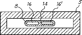
Submersed nozzle has one section vertical pipe 6, and it links to each other with last casting ladle 3 by known way.A liquid current control face 7 can be set on the top of submersed nozzle, the described mouth of a river extend downwards and in following alleged expansion stem bar 8 through a auxiliary section 18 with flat distributary division, described expansion stem bar 8 has hole, the following mouth of a river 9,9 '.Expand that stem bar 8 guarantees to keep in the slab of preset distance ground moulding in crystallizer 5 with crystallizer wall and send into the melted material origin of submersed nozzle (Here it is) for 17 times at liquid level.Slab 4 is so to form, and promptly it solidifies wall and thickens from top to bottom, and its inner core must remain liquid or do not solidify fully as yet.
Also be provided with a center flow distribution plate 14 in expanding stem bar 8, it forms one with the broad side walls that expands stem bar and is used for dispensing metal liquid stream in two runners that separate 16, and the end of described runner 16 is two holes, the mouth of a river 9,9 ' that are used for discharging molten steel downwards.
Expanding on the maximum height of stem bar promptly on the end of the auxiliary section 18 that joins with pipe 6, preferably flow channel cross-section 10 is identical with the upper end cross section of flow distribution plate 14, although this is not a major technique feature of the present invention.
According to the present invention, the area of such cross section 10 equals the area 11 of pipe 6 cross-sectional areas less than that.Clearly show that this condition among Fig. 2.Promptly look like downward expansion although it should be noted that the sidewall of auxiliary section 18 in Fig. 1 in the cross section that is parallel to the crystallizer broad side walls, they shrink in other cross section, form cross section thus and dwindle downwards.
In addition, the madial wall 12,12 ' that expands stem bar 8 is expanded downwards towards thin-walled mould 5 narrow sidewall ground and has been formed an angle α who is less than or equal to 7.5 ° with a vertical axis that it departed from 13 respectively.
According to the present invention, the bottom of flow distribution plate 14 15,15 ' has formed an angle β who is less than or equal to 7.5 ° with vertical axis 13 thus along shrinking in the face of thin-walled mould 5 narrow lateral faces.It should be understood that hypothesis satisfies above-mentioned condition, then angle β may equal or be not equal to angle α.
By two runners 16,16 ' that the opposite side of flow distribution plate 14 forms, they have a cross section perpendicular to the liquid stream that strengthens downwards, but do not make the easier sidewall that leaves of liquid stream.Because the restriction of diagonal angle α, β has avoided the liquid flow point to loose.As a result, the flow velocity in this two runners 16,16 ' is technically the flank speed that required relatively hole, the mouth of a river 9,9 ' discharge rate can obtain.
Aspect fluid dynamic, in fact submersed nozzle of the present invention or cast gate resemble a contraction chamber corresponding to cross section 11 in face of metal liquid stream, and exactly, it resembles a contraction chamber between cross section 11 and constricted cross section 10.Thereby liquid stream has maximum acceleration.Then, liquid stream slows down along two runners 16,16 ' gradually from its cross section 10 beginnings and flows downward, but liquid stream remains with sidewall and contacts.But advantageously, still increasing along the top flow velocity with flow distribution plate 14 expanding surfaces so that do not have the oxide deposition in two runners 16,16 ', and when liquid stream flowed slow or too early deceleration is flowed, such oxide deposition had appeared in this zone.For this reason, this two runners 16,16 ' cross-sectional area are preferably between the wideest cross section of the highest cross section 10 that expands stem bar and flow distribution plate and continue to dwindle.Suppose to be provided with as shown in Figure 1 described edge 19,19 ' and these edges tilt with an angle that is equal to or greater than angle α, then for example can obtain above-mentioned condition by the upper area that above-mentioned flow distribution plate 14 so is set.So, the runner that begins to form owing to the top edge 19,19 ' that leaves flow distribution plate 14 16, two upper areas of 16 ' will be before being positioned at the expansion area starting point of effective expansion stem bar 8 shrink slightly.
Those of ordinary skill in the art is submersed nozzle embodiment and make possible supplemental content and/or modification side under the prerequisite that does not exceed the scope of the invention according to the present invention as described hereinbefore
Claims (7)
1. submersed nozzle of from a casting ladle (3) with almost changeless plug mouthful, sending molten alloy or molten metal (2) by gravity, slab (4) is formed by the molten bath with liquid level (17) in the crystallizer (5) of band cooling wall, described crystallizer is that extend substantially vertically by four and the length of two sides its level cross-sectionn obviously constitutes greater than the wallboard of the length of two other side, submersed nozzle (1) comprises one section that link to each other with last casting ladle (3) and downward and hole, the band mouth of a river, bottom (9,9 ') (6) are managed in vertically going up that flat distributary division or expansion stem bar (8) link to each other, the runner (16 of relative two partitions that form by one flow distribution plate (14) of the below, surface (17) of the slab (4) that hole, described mouth of a river extended distance crystallizer (5) wall certain distance ground forms, 16 '), it is characterized in that expansion stem bar (8) surface area in the highest cross section (10) is less than last pipe (6) surface area; Expanding stem bar (8) has towards the madial wall (12 of the narrow sidewall of crystallizer (5), 12 '), the relative vertical axis of described madial wall (13) departs from the symmetry expansion from the top down and has formed an angle α who is less than or equal to 7.5 ° with this, the bottom of flow distribution plate (14) is to the narrow sidewall shrink of crystallizer, two angle β that are less than or equal to 7.5 ° between its sidewall (15,15 ') and this vertical axis, have been formed thus.
2. submersed nozzle as claimed in claim 1, it is characterized in that, flow distribution plate (14) from hole, the mouth of a river (9,9 ') the highest narrow cross section (10) that stretches to expansion stem bar (8) is worked in expansion stem bar (8) bottom that is in the same horizontal plane, thereby formed two perpendicular to molten alloy or metal liquid stream to direction on have sidewall (15 Breadth Maximum and described from this flow distribution plate from top to bottom or at least, 15 ') begin down have the runner (16,16 ') that cross-sectional area increases from it near the zone of vertical axis.
3. submersed nozzle as claimed in claim 2, it is characterized in that, basically link to each other with last pipe (6) by a taper fit portion (18) with the level flow distribution plate of the highest narrow cross section (14) upper end of expanding stem bar (8), and at last pipe (6) and sidewall (15,15 ') from being provided with flow distribution plate (14) upper side wall (19,19 ') of expansion between its flow distribution plate that begins to shrink (14) maximum region.
4. submersed nozzle as claimed in claim 3, it is characterized in that, the upper side wall (19 of expansion, 19 ') formed a angle with vertical axis more than or equal to α, this runner (16,16 ') therefore starting point has constant or that dwindle and causes liquid stream to increase the cross section of accelerating thus, till the Breadth Maximum district of flow distribution plate (14).
5. as each the described submersed nozzle among the claim 1-4, it is characterized in that, be provided with liquid current control face (7) on the top of pipe (6).
6. as each the described submersed nozzle among the claim 1-4, it is characterized in that pipe (6) directly is connected by flange with casting ladle (3) bottom, is provided with liquid current control face in this casting ladle.
7. as each the described submersed nozzle among the claim 1-4, it is characterized in that pipe (6) links to each other with liquid current control pull rod device bottom casting ladle (3) by flange by known mode itself.
Applications Claiming Priority (2)
| Application Number | Priority Date | Filing Date | Title |
|---|---|---|---|
| ITMI96A001243 | 1996-06-19 | ||
| IT96MI001243A IT1284035B1 (en) | 1996-06-19 | 1996-06-19 | DIVER FOR CONTINUOUS CASTING OF THIN SLABS |
Publications (2)
| Publication Number | Publication Date |
|---|---|
| CN1222104A CN1222104A (en) | 1999-07-07 |
| CN1072538C true CN1072538C (en) | 2001-10-10 |
Family
ID=11374446
Family Applications (1)
| Application Number | Title | Priority Date | Filing Date |
|---|---|---|---|
| CN97195649A Expired - Lifetime CN1072538C (en) | 1996-06-19 | 1997-06-16 | Submerged nozzle for continuous casting of thin slabs |
Country Status (13)
| Country | Link |
|---|---|
| US (1) | US6152336A (en) |
| EP (1) | EP0925132B1 (en) |
| JP (1) | JP3919228B2 (en) |
| CN (1) | CN1072538C (en) |
| AT (1) | ATE195896T1 (en) |
| AU (1) | AU717406B2 (en) |
| BR (1) | BR9709860A (en) |
| CA (1) | CA2257486C (en) |
| DE (1) | DE69702984T2 (en) |
| ES (1) | ES2150781T3 (en) |
| IT (1) | IT1284035B1 (en) |
| WO (1) | WO1997048512A1 (en) |
| ZA (1) | ZA974619B (en) |
Families Citing this family (26)
| Publication number | Priority date | Publication date | Assignee | Title |
|---|---|---|---|---|
| DE19724232C2 (en) * | 1997-06-03 | 1999-04-15 | Mannesmann Ag | Method and device for producing slabs |
| ES2214796T3 (en) * | 1998-11-20 | 2004-09-16 | Sms Demag Ag | FOUNDATION IMMERSION TUBE TO INTRODUCE FOUNDED MASS IN A COQUILLA FOR CONTINUOUS FOUNDATION, ESPECIALLY OF FLAT PRODUCTS. |
| BE1013745A3 (en) * | 2000-10-10 | 2002-07-02 | Ct De Rech S Metallurg Ass San | Method and device for casting continuous steel chemical composition a mixed. |
| DE10203594C1 (en) * | 2002-01-23 | 2003-05-15 | Sms Demag Ag | Submerged nozzle for a metallurgical vessel located upstream of a casting device has a cross-section expanding from a circular inlet cross-section to an opening cross-section in the direction of its opening |
| KR20050113230A (en) * | 2003-03-17 | 2005-12-01 | 비수비우스 크루서블 컴패니 | Submerged entry nozzle with dynamic stabilization |
| DE50301315D1 (en) | 2003-08-01 | 2006-02-16 | Hof Te Fiennes N V | Casting system and method for casting non-ferrous molten metals |
| KR100551997B1 (en) * | 2003-08-27 | 2006-02-20 | 조선내화 주식회사 | submerged entry nozzle for continuous casting |
| WO2005021187A1 (en) * | 2003-08-27 | 2005-03-10 | Chosun Refractories Co., Ltd. | Submerged entry nozzle for continuous casting |
| DE602005010487D1 (en) | 2005-04-07 | 2008-11-27 | Giovanni Arvedi | METHOD AND SYSTEM FOR PRODUCING METAL STRIPS AND PLATES WITHOUT A CONTINUITY LOSS BETWEEN THE CONTINUOUS CASTING AND ROLLING |
| ES2331372T3 (en) | 2005-07-19 | 2009-12-30 | Giovanni Arvedi | PROCESS AND RELATED PLANT FOR MANUFACTURING WITHOUT INTERRUPTION OF LONG STEEL PRODUCTS. |
| BRPI0520363A2 (en) | 2005-07-19 | 2009-09-29 | Giovanni Arvedi | steel sheet making process, and, steel sheet making plant |
| ATE450332T1 (en) * | 2006-05-11 | 2009-12-15 | Giovanni Arvedi | IMMERSION CASTING TUBE FOR CONTINUOUS CASTING OF STEEL |
| DE102009012985A1 (en) * | 2009-03-12 | 2010-09-23 | Salzgitter Flachstahl Gmbh | Casting nozzle for a horizontal strip casting plant |
| US8905335B1 (en) * | 2009-06-10 | 2014-12-09 | The United States Of America, As Represented By The Secretary Of The Navy | Casting nozzle with dimensional repeatability for viscous liquid dispensing |
| KR101170673B1 (en) * | 2010-01-18 | 2012-08-03 | 조선내화 주식회사 | Immersion nozzle for casting and continuous casting apparatus including the same |
| ITMI20112292A1 (en) | 2011-12-16 | 2013-06-17 | Arvedi Steel Engineering S P A | SUPPORT AND OSCILLATION DEVICE FOR LINGOTTER IN CONTINUOUS CASTING SYSTEMS |
| RU2679664C2 (en) | 2014-06-11 | 2019-02-12 | Арведи Стил Энджиниринг С.П.А. | Nozzle for molding thin slabs for distributing molten metal at high mass-flow rate |
| CN104057077A (en) * | 2014-07-08 | 2014-09-24 | 华耐国际(宜兴)高级陶瓷有限公司 | High-pulling-speed sheet billet immersion-type water opening |
| CN104907540B (en) * | 2015-06-15 | 2017-03-08 | 江苏大学 | A kind of method of the liquid pouring of electroslag continuous casting billet of strip steel water diverter |
| RU2756838C2 (en) * | 2017-05-15 | 2021-10-06 | ВЕЗУВИУС Ю Эс Эй КОРПОРЕЙШН | Cup of an asymmetric shape for casting slabs and metallurgical plant for casting metal that includes it |
| AU2018380646B2 (en) * | 2017-12-04 | 2023-07-27 | Norsk Hydro Asa | Casting apparatus and casting method |
| TW202000340A (en) | 2018-06-07 | 2020-01-01 | 日商日本製鐵股份有限公司 | Device and method for controlling steel flow in mold for thin slab casting |
| CN111974981B (en) * | 2019-05-23 | 2023-08-29 | 维苏威集团有限公司 | Casting nozzle |
| JP7367370B2 (en) * | 2019-07-31 | 2023-10-24 | セイコーエプソン株式会社 | Liquid injection device and method of controlling the liquid injection device |
| CN110918962A (en) * | 2019-11-18 | 2020-03-27 | 张家港宏昌钢板有限公司 | Retaining wall type continuous casting tundish |
| CN110695349B (en) * | 2019-11-21 | 2024-03-12 | 辽宁科技大学 | CSP sheet billet continuous casting high-pulling-speed submerged nozzle and manufacturing method thereof |
Citations (1)
| Publication number | Priority date | Publication date | Assignee | Title |
|---|---|---|---|---|
| WO1989012519A1 (en) * | 1988-06-16 | 1989-12-28 | Davy (Distington) Limited | Refractory feed tube |
Family Cites Families (6)
| Publication number | Priority date | Publication date | Assignee | Title |
|---|---|---|---|---|
| DE4142447C3 (en) * | 1991-06-21 | 1999-09-09 | Mannesmann Ag | Immersion nozzle - thin slab |
| US5785880A (en) * | 1994-03-31 | 1998-07-28 | Vesuvius Usa | Submerged entry nozzle |
| AT400935B (en) * | 1994-07-25 | 1996-04-25 | Voest Alpine Ind Anlagen | SUBMERSIBLE PIPE |
| IT1267284B1 (en) * | 1994-08-08 | 1997-01-28 | Danieli Off Mecc | CONTINUOUS CASTING UNLOADER |
| IT1267299B1 (en) * | 1994-09-30 | 1997-01-28 | Danieli Off Mecc | UNLOADER FOR CRYSTALLIZER FOR CONTINUOUS CASTING OF THIN Slabs |
| DE4436990C1 (en) * | 1994-10-07 | 1995-12-07 | Mannesmann Ag | Immersed pouring pipe where the outer wall acts as a spacer |
-
1996
- 1996-06-19 IT IT96MI001243A patent/IT1284035B1/en active IP Right Grant
-
1997
- 1997-05-27 ZA ZA9704619A patent/ZA974619B/en unknown
- 1997-06-16 CN CN97195649A patent/CN1072538C/en not_active Expired - Lifetime
- 1997-06-16 AT AT97928424T patent/ATE195896T1/en active
- 1997-06-16 BR BR9709860A patent/BR9709860A/en not_active IP Right Cessation
- 1997-06-16 JP JP50263898A patent/JP3919228B2/en not_active Expired - Lifetime
- 1997-06-16 US US09/194,687 patent/US6152336A/en not_active Expired - Lifetime
- 1997-06-16 EP EP97928424A patent/EP0925132B1/en not_active Expired - Lifetime
- 1997-06-16 WO PCT/IT1997/000135 patent/WO1997048512A1/en active IP Right Grant
- 1997-06-16 CA CA002257486A patent/CA2257486C/en not_active Expired - Lifetime
- 1997-06-16 DE DE69702984T patent/DE69702984T2/en not_active Expired - Lifetime
- 1997-06-16 AU AU32726/97A patent/AU717406B2/en not_active Expired
- 1997-06-16 ES ES97928424T patent/ES2150781T3/en not_active Expired - Lifetime
Patent Citations (1)
| Publication number | Priority date | Publication date | Assignee | Title |
|---|---|---|---|---|
| WO1989012519A1 (en) * | 1988-06-16 | 1989-12-28 | Davy (Distington) Limited | Refractory feed tube |
Also Published As
| Publication number | Publication date |
|---|---|
| EP0925132B1 (en) | 2000-08-30 |
| ZA974619B (en) | 1998-01-23 |
| AU3272697A (en) | 1998-01-07 |
| CA2257486A1 (en) | 1997-12-24 |
| JP3919228B2 (en) | 2007-05-23 |
| WO1997048512A1 (en) | 1997-12-24 |
| EP0925132A1 (en) | 1999-06-30 |
| AU717406B2 (en) | 2000-03-23 |
| DE69702984D1 (en) | 2000-10-05 |
| DE69702984T2 (en) | 2000-12-28 |
| CN1222104A (en) | 1999-07-07 |
| IT1284035B1 (en) | 1998-05-08 |
| US6152336A (en) | 2000-11-28 |
| CA2257486C (en) | 2005-03-08 |
| ES2150781T3 (en) | 2000-12-01 |
| JP2000512909A (en) | 2000-10-03 |
| ITMI961243A1 (en) | 1997-12-19 |
| ITMI961243A0 (en) | 1996-06-19 |
| ATE195896T1 (en) | 2000-09-15 |
| BR9709860A (en) | 1999-08-10 |
Similar Documents
| Publication | Publication Date | Title |
|---|---|---|
| CN1072538C (en) | Submerged nozzle for continuous casting of thin slabs | |
| CN1035070A (en) | The apparatus for pouring of double-roller continuous casting machine | |
| PL179859B1 (en) | Permanent mould for use in continuous casting processes | |
| US5603860A (en) | Immersed casting tube | |
| ITUD940137A1 (en) | CONTINUOUS CASTING UNLOADER | |
| CN102834206A (en) | Immersed nozzle for casting and continuously casting apparatus including same | |
| RU2127171C1 (en) | Submersible casting tube | |
| KR100654889B1 (en) | Nozzle for continuous casting | |
| CN209918882U (en) | Continuous casting crystallizer immersion nozzle | |
| JPH115144A (en) | Continuous casting of beam blank | |
| JPH03110048A (en) | Tundish stopper | |
| JPH09108793A (en) | Continuous casting method and straight immersion nozzle | |
| JPH04220148A (en) | Molten steel supplying nozzle | |
| JPH10128506A (en) | Immersion nozzle for continuous casting | |
| KR20050016086A (en) | Casting system and method for pouring nonferrous metal molten masses | |
| US6336575B1 (en) | Submerged nozzle for slab continuous casting moulds | |
| CN218252877U (en) | Tundish current stabilizer for continuous casting | |
| CN218460855U (en) | High-temperature smelting molten steel flow stabilizer | |
| KR101962230B1 (en) | A Submerged nozzle for continuous casting | |
| SK166399A3 (en) | Method and device for producing slabs | |
| KR100485404B1 (en) | Partial Immersion Nozzle for Continuous Casting of Thin Slabs | |
| JPH10263785A (en) | Casting method and casting metallic mold | |
| CN2288798Y (en) | tubular continuous casting mould | |
| RU2148469C1 (en) | Metal continuous casting plant | |
| KR19990012672U (en) | Immersion nozzle for continuous casting with upward discharge port |
Legal Events
| Date | Code | Title | Description |
|---|---|---|---|
| C06 | Publication | ||
| PB01 | Publication | ||
| C10 | Entry into substantive examination | ||
| SE01 | Entry into force of request for substantive examination | ||
| C14 | Grant of patent or utility model | ||
| GR01 | Patent grant | ||
| CX01 | Expiry of patent term |
Granted publication date: 20011010 |
|
| CX01 | Expiry of patent term |