CN107206993B - Control device and method for operating a brake system of a vehicle - Google Patents
Control device and method for operating a brake system of a vehicle Download PDFInfo
- Publication number
- CN107206993B CN107206993B CN201680009573.8A CN201680009573A CN107206993B CN 107206993 B CN107206993 B CN 107206993B CN 201680009573 A CN201680009573 A CN 201680009573A CN 107206993 B CN107206993 B CN 107206993B
- Authority
- CN
- China
- Prior art keywords
- brake
- vehicle
- brake booster
- information
- hydraulic unit
- Prior art date
- Legal status (The legal status is an assumption and is not a legal conclusion. Google has not performed a legal analysis and makes no representation as to the accuracy of the status listed.)
- Active
Links
Images

Classifications
-
- B—PERFORMING OPERATIONS; TRANSPORTING
- B60—VEHICLES IN GENERAL
- B60T—VEHICLE BRAKE CONTROL SYSTEMS OR PARTS THEREOF; BRAKE CONTROL SYSTEMS OR PARTS THEREOF, IN GENERAL; ARRANGEMENT OF BRAKING ELEMENTS ON VEHICLES IN GENERAL; PORTABLE DEVICES FOR PREVENTING UNWANTED MOVEMENT OF VEHICLES; VEHICLE MODIFICATIONS TO FACILITATE COOLING OF BRAKES
- B60T13/00—Transmitting braking action from initiating means to ultimate brake actuator with power assistance or drive; Brake systems incorporating such transmitting means, e.g. air-pressure brake systems
- B60T13/10—Transmitting braking action from initiating means to ultimate brake actuator with power assistance or drive; Brake systems incorporating such transmitting means, e.g. air-pressure brake systems with fluid assistance, drive, or release
- B60T13/66—Electrical control in fluid-pressure brake systems
- B60T13/662—Electrical control in fluid-pressure brake systems characterised by specified functions of the control system components
-
- B—PERFORMING OPERATIONS; TRANSPORTING
- B60—VEHICLES IN GENERAL
- B60T—VEHICLE BRAKE CONTROL SYSTEMS OR PARTS THEREOF; BRAKE CONTROL SYSTEMS OR PARTS THEREOF, IN GENERAL; ARRANGEMENT OF BRAKING ELEMENTS ON VEHICLES IN GENERAL; PORTABLE DEVICES FOR PREVENTING UNWANTED MOVEMENT OF VEHICLES; VEHICLE MODIFICATIONS TO FACILITATE COOLING OF BRAKES
- B60T13/00—Transmitting braking action from initiating means to ultimate brake actuator with power assistance or drive; Brake systems incorporating such transmitting means, e.g. air-pressure brake systems
- B60T13/10—Transmitting braking action from initiating means to ultimate brake actuator with power assistance or drive; Brake systems incorporating such transmitting means, e.g. air-pressure brake systems with fluid assistance, drive, or release
- B60T13/66—Electrical control in fluid-pressure brake systems
- B60T13/68—Electrical control in fluid-pressure brake systems by electrically-controlled valves
- B60T13/686—Electrical control in fluid-pressure brake systems by electrically-controlled valves in hydraulic systems or parts thereof
-
- B—PERFORMING OPERATIONS; TRANSPORTING
- B60—VEHICLES IN GENERAL
- B60T—VEHICLE BRAKE CONTROL SYSTEMS OR PARTS THEREOF; BRAKE CONTROL SYSTEMS OR PARTS THEREOF, IN GENERAL; ARRANGEMENT OF BRAKING ELEMENTS ON VEHICLES IN GENERAL; PORTABLE DEVICES FOR PREVENTING UNWANTED MOVEMENT OF VEHICLES; VEHICLE MODIFICATIONS TO FACILITATE COOLING OF BRAKES
- B60T13/00—Transmitting braking action from initiating means to ultimate brake actuator with power assistance or drive; Brake systems incorporating such transmitting means, e.g. air-pressure brake systems
- B60T13/74—Transmitting braking action from initiating means to ultimate brake actuator with power assistance or drive; Brake systems incorporating such transmitting means, e.g. air-pressure brake systems with electrical assistance or drive
- B60T13/745—Transmitting braking action from initiating means to ultimate brake actuator with power assistance or drive; Brake systems incorporating such transmitting means, e.g. air-pressure brake systems with electrical assistance or drive acting on a hydraulic system, e.g. a master cylinder
-
- B—PERFORMING OPERATIONS; TRANSPORTING
- B60—VEHICLES IN GENERAL
- B60T—VEHICLE BRAKE CONTROL SYSTEMS OR PARTS THEREOF; BRAKE CONTROL SYSTEMS OR PARTS THEREOF, IN GENERAL; ARRANGEMENT OF BRAKING ELEMENTS ON VEHICLES IN GENERAL; PORTABLE DEVICES FOR PREVENTING UNWANTED MOVEMENT OF VEHICLES; VEHICLE MODIFICATIONS TO FACILITATE COOLING OF BRAKES
- B60T17/00—Component parts, details, or accessories of power brake systems not covered by groups B60T8/00, B60T13/00 or B60T15/00, or presenting other characteristic features
- B60T17/18—Safety devices; Monitoring
- B60T17/22—Devices for monitoring or checking brake systems; Signal devices
- B60T17/221—Procedure or apparatus for checking or keeping in a correct functioning condition of brake systems
-
- B—PERFORMING OPERATIONS; TRANSPORTING
- B60—VEHICLES IN GENERAL
- B60T—VEHICLE BRAKE CONTROL SYSTEMS OR PARTS THEREOF; BRAKE CONTROL SYSTEMS OR PARTS THEREOF, IN GENERAL; ARRANGEMENT OF BRAKING ELEMENTS ON VEHICLES IN GENERAL; PORTABLE DEVICES FOR PREVENTING UNWANTED MOVEMENT OF VEHICLES; VEHICLE MODIFICATIONS TO FACILITATE COOLING OF BRAKES
- B60T7/00—Brake-action initiating means
- B60T7/02—Brake-action initiating means for personal initiation
-
- B—PERFORMING OPERATIONS; TRANSPORTING
- B60—VEHICLES IN GENERAL
- B60T—VEHICLE BRAKE CONTROL SYSTEMS OR PARTS THEREOF; BRAKE CONTROL SYSTEMS OR PARTS THEREOF, IN GENERAL; ARRANGEMENT OF BRAKING ELEMENTS ON VEHICLES IN GENERAL; PORTABLE DEVICES FOR PREVENTING UNWANTED MOVEMENT OF VEHICLES; VEHICLE MODIFICATIONS TO FACILITATE COOLING OF BRAKES
- B60T7/00—Brake-action initiating means
- B60T7/12—Brake-action initiating means for automatic initiation; for initiation not subject to will of driver or passenger
-
- B—PERFORMING OPERATIONS; TRANSPORTING
- B60—VEHICLES IN GENERAL
- B60T—VEHICLE BRAKE CONTROL SYSTEMS OR PARTS THEREOF; BRAKE CONTROL SYSTEMS OR PARTS THEREOF, IN GENERAL; ARRANGEMENT OF BRAKING ELEMENTS ON VEHICLES IN GENERAL; PORTABLE DEVICES FOR PREVENTING UNWANTED MOVEMENT OF VEHICLES; VEHICLE MODIFICATIONS TO FACILITATE COOLING OF BRAKES
- B60T8/00—Arrangements for adjusting wheel-braking force to meet varying vehicular or ground-surface conditions, e.g. limiting or varying distribution of braking force
- B60T8/32—Arrangements for adjusting wheel-braking force to meet varying vehicular or ground-surface conditions, e.g. limiting or varying distribution of braking force responsive to a speed condition, e.g. acceleration or deceleration
- B60T8/88—Arrangements for adjusting wheel-braking force to meet varying vehicular or ground-surface conditions, e.g. limiting or varying distribution of braking force responsive to a speed condition, e.g. acceleration or deceleration with failure responsive means, i.e. means for detecting and indicating faulty operation of the speed responsive control means
- B60T8/885—Arrangements for adjusting wheel-braking force to meet varying vehicular or ground-surface conditions, e.g. limiting or varying distribution of braking force responsive to a speed condition, e.g. acceleration or deceleration with failure responsive means, i.e. means for detecting and indicating faulty operation of the speed responsive control means using electrical circuitry
-
- B—PERFORMING OPERATIONS; TRANSPORTING
- B60—VEHICLES IN GENERAL
- B60W—CONJOINT CONTROL OF VEHICLE SUB-UNITS OF DIFFERENT TYPE OR DIFFERENT FUNCTION; CONTROL SYSTEMS SPECIALLY ADAPTED FOR HYBRID VEHICLES; ROAD VEHICLE DRIVE CONTROL SYSTEMS FOR PURPOSES NOT RELATED TO THE CONTROL OF A PARTICULAR SUB-UNIT
- B60W40/00—Estimation or calculation of non-directly measurable driving parameters for road vehicle drive control systems not related to the control of a particular sub unit, e.g. by using mathematical models
- B60W40/12—Estimation or calculation of non-directly measurable driving parameters for road vehicle drive control systems not related to the control of a particular sub unit, e.g. by using mathematical models related to parameters of the vehicle itself, e.g. tyre models
-
- B—PERFORMING OPERATIONS; TRANSPORTING
- B60—VEHICLES IN GENERAL
- B60W—CONJOINT CONTROL OF VEHICLE SUB-UNITS OF DIFFERENT TYPE OR DIFFERENT FUNCTION; CONTROL SYSTEMS SPECIALLY ADAPTED FOR HYBRID VEHICLES; ROAD VEHICLE DRIVE CONTROL SYSTEMS FOR PURPOSES NOT RELATED TO THE CONTROL OF A PARTICULAR SUB-UNIT
- B60W50/00—Details of control systems for road vehicle drive control not related to the control of a particular sub-unit, e.g. process diagnostic or vehicle driver interfaces
- B60W50/02—Ensuring safety in case of control system failures, e.g. by diagnosing, circumventing or fixing failures
- B60W50/0205—Diagnosing or detecting failures; Failure detection models
-
- B—PERFORMING OPERATIONS; TRANSPORTING
- B60—VEHICLES IN GENERAL
- B60T—VEHICLE BRAKE CONTROL SYSTEMS OR PARTS THEREOF; BRAKE CONTROL SYSTEMS OR PARTS THEREOF, IN GENERAL; ARRANGEMENT OF BRAKING ELEMENTS ON VEHICLES IN GENERAL; PORTABLE DEVICES FOR PREVENTING UNWANTED MOVEMENT OF VEHICLES; VEHICLE MODIFICATIONS TO FACILITATE COOLING OF BRAKES
- B60T2260/00—Interaction of vehicle brake system with other systems
- B60T2260/06—Active Suspension System
-
- B—PERFORMING OPERATIONS; TRANSPORTING
- B60—VEHICLES IN GENERAL
- B60T—VEHICLE BRAKE CONTROL SYSTEMS OR PARTS THEREOF; BRAKE CONTROL SYSTEMS OR PARTS THEREOF, IN GENERAL; ARRANGEMENT OF BRAKING ELEMENTS ON VEHICLES IN GENERAL; PORTABLE DEVICES FOR PREVENTING UNWANTED MOVEMENT OF VEHICLES; VEHICLE MODIFICATIONS TO FACILITATE COOLING OF BRAKES
- B60T2270/00—Further aspects of brake control systems not otherwise provided for
- B60T2270/40—Failsafe aspects of brake control systems
- B60T2270/402—Back-up
-
- B—PERFORMING OPERATIONS; TRANSPORTING
- B60—VEHICLES IN GENERAL
- B60T—VEHICLE BRAKE CONTROL SYSTEMS OR PARTS THEREOF; BRAKE CONTROL SYSTEMS OR PARTS THEREOF, IN GENERAL; ARRANGEMENT OF BRAKING ELEMENTS ON VEHICLES IN GENERAL; PORTABLE DEVICES FOR PREVENTING UNWANTED MOVEMENT OF VEHICLES; VEHICLE MODIFICATIONS TO FACILITATE COOLING OF BRAKES
- B60T2270/00—Further aspects of brake control systems not otherwise provided for
- B60T2270/40—Failsafe aspects of brake control systems
- B60T2270/413—Plausibility monitoring, cross check, redundancy
-
- B—PERFORMING OPERATIONS; TRANSPORTING
- B60—VEHICLES IN GENERAL
- B60T—VEHICLE BRAKE CONTROL SYSTEMS OR PARTS THEREOF; BRAKE CONTROL SYSTEMS OR PARTS THEREOF, IN GENERAL; ARRANGEMENT OF BRAKING ELEMENTS ON VEHICLES IN GENERAL; PORTABLE DEVICES FOR PREVENTING UNWANTED MOVEMENT OF VEHICLES; VEHICLE MODIFICATIONS TO FACILITATE COOLING OF BRAKES
- B60T2270/00—Further aspects of brake control systems not otherwise provided for
- B60T2270/40—Failsafe aspects of brake control systems
- B60T2270/414—Power supply failure
-
- B—PERFORMING OPERATIONS; TRANSPORTING
- B60—VEHICLES IN GENERAL
- B60Y—INDEXING SCHEME RELATING TO ASPECTS CROSS-CUTTING VEHICLE TECHNOLOGY
- B60Y2400/00—Special features of vehicle units
- B60Y2400/81—Braking systems
Abstract
The invention relates to a control device (14) for at least one brake system of a vehicle, comprising an electronic unit (15), wherein the electronic unit (15) is designed to: the determination takes place taking into account a braking predefined (16) by a driver of the vehicle or an automatic control device (18) of the vehicle and additionally taking into account at least one first information item (22) and at least one second information item (24): for which first target portion a corresponding brake pressure increase is to be achieved by means of the at least one hydraulic unit (10) and for which second target portion a corresponding brake pressure increase is to be achieved by means of the brake booster (12), the first information relating to a current availability of the at least one hydraulic unit (10) of the brake system and the second information relating to a current availability of the brake booster (12) of the brake system; and the at least one hydraulic machine (10) and/or the brake booster (10) are/is actuated in such a way that the respective brake pressure increase can be achieved for the first target portion by means of the at least one hydraulic machine (10) and for the second target portion by means of the brake booster (12). The invention further relates to a method for operating a brake system of a vehicle.
Description
Technical Field
The present invention relates to a control device for a brake system of a vehicle. The invention also relates to a brake system for a vehicle and to a vehicle which is designed for automated driving. The invention further relates to a method for operating a brake system of a vehicle and to a method for automatically driving a vehicle.
Background
DE 102013203824 a1 describes a control device for a brake system of a vehicle and a method for operating a brake system of a vehicle. When the control device is used or when the corresponding method is executed, at least one first hydraulic component of the corresponding brake system and a second hydraulic component of the same brake system are actuated according to a target operating mode to be executed, as a result of which at least one brake pressure is to be able to be set in wheel brake cylinders of the brake system as a function of a brake specification. First, a target operating mode to be executed is selected from at least two executable operating modes. In particular, the type of vehicle of the vehicle equipped with the respective brake system and/or the type of at least one component of the brake system is taken into account when selecting the target operating mode to be executed.
Disclosure of Invention
The invention relates to a control device for a brake system of a vehicle, to a brake system for a vehicle, to a vehicle designed for automated driving, to a method for operating a brake system of a vehicle, and to a method for automated driving of a vehicle.
By means of the invention, functional impairment/malfunction of at least one hydraulic unit of the brake system or of a brake booster of the brake system can be compensated for quickly and reliably. For example, with the present invention, the brake booster can reliably execute the brake specification even in the event of a complete failure of at least one hydraulic unit of the brake system. It is also possible to compensate for a complete failure of the brake booster by: the braking is performed quickly and reliably by means of the at least one hydraulic machine. The invention thus contributes to an increase in the safety standards of the brake system achieved in this way.
The invention provides, in particular, improved safety standards for vehicles designed for automated driving. When autonomous braking is performed (i.e., braking which is required by the automatic control device without actuation of the brake actuating element by the driver), a functional impairment/malfunction of the at least one hydraulic unit can advantageously be compensated for by means of the brake booster. Likewise, a functional impairment/malfunction of the brake booster can be compensated for by means of the at least one hydraulic unit. The required autonomous braking can thus be carried out with a high probability even in the case of a high first failure rate of the at least one hydraulic machine and/or a high second failure rate of the brake booster. This satisfies the core requirements for automated/highly automated driving.
For example, the electronic unit can be designed at least for: optionally, taking into account the braking predefined, the at least one first information and the at least one second information, it is decided to: the respective brake pressure increase should be realized by 100% by means of the at least one hydraulic machine and 0% by means of the brake booster, or should be realized by 0% by means of the at least one hydraulic machine and 100% by means of the brake booster. As an optional refinement, the electronic unit can also be designed to: the corresponding brake pressure increase should be achieved by x% by means of the at least one hydraulic unit 10 and (100-x)% by means of the brake booster 12, at least one value between 0 and 100 being able to represent x. (x can also be equal to 0 and/or 100.) this allows a high degree of flexibility in response to the fact that the at least one hydraulic unit or the brake booster can only be used to a limited extent or can no longer be used.
In an advantageous embodiment, the electronic device can be designed to: deciding, at least in consideration of a first signal as the at least one first information and/or a second signal as the at least one second information: for which first target portion the respective brake pressure increase is to be achieved by means of the at least one hydraulic machine and for which second target portion the respective brake pressure increase is to be achieved by means of the brake booster, the first signal relates to the supply of at least one first supply current to the at least one hydraulic machine, and the second signal relates to the supply of a second supply current to the brake booster. The electronic unit can thus react quickly to an insufficient supply of power/energy to the at least one hydraulic unit or to the brake booster.
Furthermore, the electronic mechanism can additionally be designed to: it is determined whether the stationary state of the vehicle is to be fixed by means of an automatic parking brake or by locking the transmission of the vehicle by means of a parking pawl, and the automatic parking brake or the parking blade (parklink) is actuated accordingly. The stationary state of the vehicle can thus optionally be fixed by means of the automatic parking brake or by locking the transmission of the vehicle by means of the parking pawl.
The advantages listed above are also guaranteed for a braking system with such an electronic mechanism.
In an advantageous embodiment of the brake system, the at least one hydraulic unit is integrated into an ESP system of the brake system. Preferably, in this case, the first subunit of the control device is integrated into an ESP control unit of the ESP system. Alternatively or additionally, the second subunit of the control device can be integrated into a brake booster control of the brake booster. The at least one third subunit of the control device can optionally also be integrated into other components, such as, for example, a drive train control of a drive train of the vehicle. This eliminates the need to construct a separate housing for the control device.
Preferably, the at least one hydraulic machine is connected to a first supply network or supply network part (stromversorgingsnetzoil) formed in the brake system, via which it can be connected or connected to a first energy source of the vehicle, and the brake booster is connected to a second supply network or supply network part formed in the brake system, via which it can be connected or connected to a second energy source of the vehicle. A failure of the first energy source and a functional impairment of the at least one hydraulic unit associated therewith can thus be compensated for by means of a further ensured functional capability of the brake booster. Accordingly, a failure of the second energy source which triggers a functional impairment of the brake booster can still be compensated for by the at least one first supply current which continues to be supplied to the at least one hydraulic unit.
In a further advantageous embodiment of the brake system, the automatic parking brake is likewise connected to the first supply network or supply network part, and the parking pawl is likewise connected to the second supply network or supply network part. A functional impairment of the automatic parking brake triggered by a failure of the first energy source can thus be compensated for by means of the parking pawl. Accordingly, functional impairment of the parking pawl, which is triggered by a failure of the second energy source, can also be compensated for by means of the automatic parking brake.
The advantages explained above are also ensured for a vehicle designed for automated driving by means of its corresponding brake system. The vehicle additionally comprises the automatic control device, which is designed to: a target trajectory of the vehicle is determined taking into account at least one sensor signal of at least one environment detection sensor of the vehicle, and the braking predefined is determined as a function of the determined target trajectory of the vehicle and of the current speed and is output to the control device.
The advantages described above can also be achieved by implementing a corresponding method for operating a brake system of a vehicle. The method can be improved according to the above-described embodiments of the brake system.
In an advantageous embodiment of the method, at least one of the following is acquired as the at least one first information: whether at least one first supply current is supplied to the at least one hydraulic machine and/or at least as the at least one second information: whether a second supply current is provided to the brake booster. For example, at least: whether a first energy source of the vehicle, which is connected to the at least one hydraulic unit via a first supply network, is defective and/or at least one second information item can be obtained, namely: a failure of a second energy source of the vehicle, which is connected to the brake booster via a second supply network. The respective information can then be reacted to by means of an optimized decision about the first target portion of the respective brake pressure increase (by means of the at least one hydraulic unit) and the second target portion of the respective brake pressure increase (by means of the brake booster).
As an advantageous development of the method, it can additionally be decided: the stationary state of the vehicle is fixed by means of an automatic parking brake or by locking the transmission of the vehicle by means of a parking pawl. This reliably prevents undesired rolling away of the vehicle even in the event of failure of one of the two energy sources of the vehicle.
The implementation of the method for automatically driving a vehicle also offers the advantages described above. It is pointed out that the method for automatically driving a vehicle can be improved according to the embodiments of the method for operating a brake system described above.
Drawings
Further features and advantages of the invention are explained below with the aid of the figures. In the drawings:
FIG. 1 shows a schematic view of an embodiment of the braking system; and is
Fig. 2 shows a flow chart for explaining an embodiment of a method for operating a brake system of a vehicle.
Detailed Description
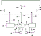
Fig. 1 shows a schematic representation of an embodiment of the brake system.
The brake system schematically shown in fig. 1 can be used in a vehicle/motor vehicle. Vehicles/motor vehicles which are designed in particular for automated driving can be equipped with the brake system of fig. 1. It is to be noted, however, that the usability of the brake system of fig. 1 is not limited to a specific vehicle type.
The brake system of fig. 1 comprises at least one wheel brake cylinder, which is not shown for the sake of greater simplicity. For example, the at least one wheel brake cylinder can be connected to a (not illustrated) master brake cylinder of the brake system via at least one brake circuit. It is to be noted that the realizability of the further described brake system is not limited to a specific number of its wheel brake cylinders, to a specific wheel brake cylinder type, to the allocation of the master brake cylinder, nor to a specific master brake cylinder type.
The brake system also has at least one hydraulic unit 10, wherein at least one brake pressure in the at least one wheel brake cylinder can be increased by means of (operation of) the at least one hydraulic unit 10. The "at least one hydraulic unit 10" can be, for example, at least one pump and/or at least one motorized piston-cylinder arrangement. Furthermore, the at least one hydraulic unit 10 can in particular also refer to a plurality of pumps of the brake system and/or a plurality of piston-cylinder units of the brake system, but also to all pumps of the brake system and/or all piston-cylinder units of the brake system. The illustration of only one hydraulic unit 10 in fig. 1 should therefore be construed merely as an example. Likewise, the constructability of the at least one hydraulic unit 10 is not limited to the at least one pump and/or the at least one motorized piston-cylinder arrangement.
The brake system also has a brake booster 12. Preferably, the brake booster 12 is an electromechanical brake booster. However, it is to be noted that the constructability of the brake system is not limited to a specific brake booster type of the brake booster 12.
The brake system also has a control device 14 with an electronic unit 15. The electronic means 15 are designed to: the at least one hydraulic unit 10 and/or the brake booster 12 are/is actuated at least taking into account a braking specification 16 of a driver of the vehicle or of an automatic control device 18 of the vehicle. Preferably, by means of the actuation of the at least one hydraulic unit 10 and/or the brake booster 12 by the electronic unit 15, at least one brake pressure increase in the at least one wheel brake cylinder can be brought about as a function of the brake specification 16. This is to be understood as meaning that a total deceleration of the vehicle, which corresponds to the braking specification 16, results from at least one brake pressure increase in the at least one wheel brake cylinder. At least one brake pressure increase in the at least one wheel brake cylinder may also be implemented in such a way that the resulting deceleration of the vehicle (from the at least one brake pressure increase) is matched to the brake specification 16 together with the generator braking torque of at least one generator-specific electric motor 20. The respective brake pressure increase in the at least one wheel brake cylinder can be caused in a wheel brake cylinder-specific manner, in a brake circuit-specific manner or identically for all wheel brake cylinders.
First of all, the electronic means 15 are designed to determine: the respective brake pressure increase should be achieved for which first target portion by means of (operation of) the at least one hydraulic unit 10 and the respective brake pressure increase should be achieved for which second target portion by means of (operation of) the brake booster 12. This determination takes place taking into account the braking specification 16 and additionally taking into account at least one first information item 22 concerning the current availability of the at least one hydraulic unit 10 and at least one second information item 24 concerning the current availability of the brake booster 12. The electronic means 15 are then designed to: the at least one hydraulic unit 10 is actuated (by means of at least one first control signal 26) and/or the brake booster 12 is actuated (by means of at least one second control signal 28) in such a way that the respective brake pressure increase can be achieved for the first target portion by means of the operation of the at least one hydraulic unit 10 and for the second target portion by means of the operation of the brake booster 12.
For the brake system of fig. 1, it can thus be predetermined 16 (freely) for each brake: whether the at least one hydraulic machine 10 should be used more/only and the brake booster 12 should be used less/not in order to carry out the predetermination, or whether the brake booster 12 should be used more/only and the at least one hydraulic machine 10 should be used less/not in order to carry out the predetermination. By taking into account the at least one first information 22 and the at least one second information 24 at the time of the decision, it can be ensured that: the subsequent actuation of the at least one hydraulic machine 10 (by means of the at least one first control signal 26) and/or of the brake booster 12 (by means of the at least one second control signal 28) is optimized with regard to the current availability of the at least one hydraulic machine 10 and the current availability of the brake booster 12. In particular, the power consumption (Arbeitsaufwand) to bring about the corresponding brake pressure increase can be specifically distributed between the at least one hydraulic unit 10 and the brake booster 12 in such a way that a reduced/cancelled availability of the at least one hydraulic unit 10 or of the brake booster 12 can be compensated. The desired brake pressure increase (which results in the brake specification 16) can also be achieved in the at least one wheel brake cylinder (wheel brake cylinder-specifically, brake circuit-specifically or the same for all wheel brake cylinders) in the case in which the at least one hydraulic unit 10 or the brake booster 12 is hardly able to be used/disabled.
Note that "decision: the determination of the first target portion and/or the second target portion is not necessarily the case, for which the first target portion the respective brake pressure increase is to be achieved by means of the at least one hydraulic unit 10 and the second target portion the respective brake pressure increase is to be achieved by means of the brake booster 12. In other words, at least one first target operating variable of the at least one hydraulic unit 10 and/or at least one second target operating variable of the brake booster 12 can also be determined/selected by means of the electronic unit 15. The at least one first target operating variable of the at least one hydraulic unit 10 may be, for example, at least one first target supply current of the at least one hydraulic unit 10 and/or at least one target rotational speed of the at least one hydraulic unit 10. Accordingly, the at least one second target operating variable of the brake booster 12 can be a second target supply current of the brake booster 12 and/or a target motor speed of the motor of the brake booster 12. However, the at least one first target operating variable and the at least one second target operating variable are not limited to the examples mentioned here. Likewise, "determining" can also mean selecting/determining at least one target operating mode of the at least one hydraulic unit 10 and the brake booster 12.
For example, the electronic means 15 are designed at least for: optionally, it is decided, taking into account the braking specification 16, the at least one first information 22 and the at least one second information 24: the respective brake pressure increase should be realized by 100% by means of (operation of) the at least one hydraulic unit 10 and 0% by means of (operation of) the brake booster 12, or should be realized by 0% by means of (operation of) the at least one hydraulic unit 10 and 100% by means of (operation of) the brake booster 12. If applicable, the corresponding brake pressure increase is effected either solely by means of the operation of the at least one hydraulic unit 10 or solely by means of the operation of the brake booster 12. In particular, in the event of a failure of the at least one hydraulic unit 10, the brake booster 12 can be engaged in this way. Accordingly, the brake booster can also be replaced by the operation of the at least one hydraulic unit 10 in the event of failure of the brake booster 12.
However, the electronic means 15 can also be designed for: taking into account the braking specification 16, the at least one first information 22 and the at least one second information 24, it is decided that: the corresponding brake pressure increase should be achieved by x% by means of (operation of) the at least one hydraulic unit 10 and (100-x)% by means of (operation of) the brake booster 12, at least one value between 0 and 100 being able to represent x. Thus, the reduced availability of the at least one hydraulic unit 10 can also be reacted to by an additional/increased operation of the brake booster 12. Likewise, the at least one hydraulic unit 10 can additionally/intensively be used when the availability of the brake booster 12 is reduced. This provides a high degree of flexibility in response to the situation in which the at least one hydraulic unit 10 or the brake booster 12 is still only available to a limited extent.
The at least one electric motor 20 can be, for example, at least one drive motor of the vehicle, at least one starter generator and/or at least one element (electric machine) in the drive train which provides a longitudinal force. "at least one electric motor 20" can refer to all elements that influence the longitudinal capacity of the vehicle.
In an advantageous development, the at least one electric motor 20 can also be actuated by the electronic means 15 by means of at least one third control signal 30. In particular, in this case, the electronic unit 15 can be designed to: taking into account the braking specification 16 and at least one third information item 32 about the current availability of the at least one electric motor 20: which at least one generator braking torque should be caused by means of the at least one electric motor 20 and the at least one electric motor 20 is controlled accordingly by means of the at least one third control signal 30. The at least one first information 22 and/or the at least one second information 24 can also be taken into account here together. The electronic means 15 can determine from this: in consideration of the braking predefined 16, the at least one third information 32 and/or the at least one generator braking torque, what brake pressure increase in the at least one wheel brake cylinder is desired, and subsequently a decision is made as to the first target share of the respective brake pressure increase and the second target share of the respective brake pressure increase.
The electronic means 15 can be designed in particular for: at least in consideration of a first signal (not sketched) as the at least one first information 22 and/or a second signal (not shown) as the at least one second information 24: for which first target portion the respective brake pressure increase is to be achieved by means of the at least one hydraulic machine 10 and for which second portion the respective brake pressure increase is to be achieved by means of the brake booster 12, the first signal relating to the supply of at least one first supply current to the at least one hydraulic machine 10 and the second signal relating to the supply of a second supply current to the brake booster 12. As a result, the electronic unit 15 can quickly react to an insufficient/cancelled supply of power to the at least one hydraulic unit 10 or brake booster 12 and be used for the following purposes: nevertheless, the maintenance in the at least one wheel brake cylinder can bring about the desired brake pressure increase (which achieves the brake specification 16). In the following, a particularly advantageous embodiment of the electronic unit 15/brake system for achieving this advantage will be discussed. However, as the at least one first information item 22, the state of the at least one hydraulic machine 10 can also be transmitted. Accordingly, the state of the brake booster 12 can be transmitted as the at least one second message 24.
The at least one hydraulic unit 10 can be integrated, for example, into an ESP system 34 of the brake system. This is particularly advantageous if the at least one hydraulic machine 10 is at least one pump. The at least one first message 22 can thus also comprise the status of the ESP system 34. In the event of a failure of the brake booster 12, in this case all its functions can be covered by means of the ESP system 34. Accordingly, in the event of a failure of the ESP system 34, its functional capacity can be assumed at least in part by the brake booster 12.
In the embodiment of fig. 1, the at least one hydraulic unit 10/the ESP system 34 can be connected to a first or supply network section 36 formed in the brake system. The term "first power supply network or supply network part 36" refers to an electronic unit via which the at least one hydraulic unit 10/the ESP system 34 can be connected or connected to a first energy source 38 of the vehicle. By means of a first energy source 38 of the vehicle, at least the at least one first supply current (via the first supply network or supply network section 36) can be supplied to the at least one hydraulic machine 10/the ESP system 34. In contrast, the brake booster 12 is connected to a second supply network or supply network part 40 which is formed in the brake system. "second power supply network or power supply network part 40" is an electronic means by which the brake booster 40 can be connected or connected to a second energy source 42 of the vehicle. Thus, the second supply current of the brake booster 12 (via the second supply grid or supply grid section 40) can be supplied to the brake booster 12 by the second energy source 42 of the vehicle. The first energy source 38 and/or the second energy source 42 can be, for example, a battery and/or a vehicle electrical system (respectively). The first signal and/or the second signal can thus be a notification signal about a malfunction of the first energy source 38/second energy source 42. Such signals can be easily evaluated by means of a simply constructed electronic means 15.
As an advantageous development, the automatic parking brake 44 can also be connected to the first supply network or supply network part 36. Furthermore, the parking pawl 46 can also be connected to the second power supply network or to the power supply network part 40.
As a result, the parking pawl 46 remains available despite the availability of the automatic parking brake 44, which was cancelled as a result of the failure of the first energy source 38. Accordingly, despite the availability of the parking pawl 46 which is cancelled as a result of the failure of the second energy source 42, the functional capability of the automatic parking brake 44 is ensured.
Preferably, in particular when the automatic parking brake 44 is connected to the first power supply network or power supply network part 36 and the parking pawl 46 is connected to the second power supply network or power supply network part 40, the electronic unit 15 is designed to: it is decided (taking into account the information 22 and 24) whether the stationary state of the vehicle should be fixed by means of the automatic parking brake 44 or by locking the transmission (not shown) of the vehicle by means of the parking pawl 46. The electronic unit 15 can then actuate the automatic parking brake 44 or the parking blade 46 accordingly (by means of at least one control signal not shown). The information 22 and 24 for the determination can also be taken into account when the automatic parking brake 44 or the parking pawl 46 is optionally used to ensure the stationary state of the vehicle. In particular, the at least one signaling signal for a failure of first energy source 38/second energy source 42 can thus be used in a versatile manner.
It is to be noted, however, that the embodiment of the electronic unit 15 described in the preceding paragraph is also advantageous if the automatic parking brake 44 is not connected to the first supply network or supply network part 36 and the parking pawl 46 is not connected to the second supply network or supply network part 40. It is likewise pointed out that other measures can also be made with the aid of the electronic device 15 with regard to the availability of the automatic parking brake 44 and/or the availability of the parking pawl 46.
It should be noted that the brake booster 12 is better designed than the automatic parking brake 44 for compensating for the cancelled availability of the at least one hydraulic unit 10/ESP system 34 on the moving vehicle. In particular, a high deceleration of the vehicle can be achieved by means of the brake booster 12 without jerking behavior.
In the embodiment of fig. 1, the control device 14/electronic unit 15 is shown as a compact unit. In an alternative embodiment, however, the first subunit of the control device 14/electronics 15 can also be integrated into the ESP control of the ESP system 34. Furthermore, a second subunit of the control device 14/electronic unit 15 can be integrated into the brake booster control of the brake booster 12. An emergency stop state management system can also be stored in the brake booster 12, which actively activates the transmission locking mechanism by means of the parking pawl 46 if necessary.
It is also possible to integrate the third subunit of the control device 14/electronic unit 15 into the motor control of the at least one electric motor 20/drive motor, as long as desired. This also makes it possible to easily dispense with equipping the control device 14 with its own housing. The at least one hydraulic unit 10/the ESP system 34 and the brake booster 12 can also be designed to: exchanging communication signals 48 between each other. The at least one electric motor 20/drive motor can also be designed for: a communication signal 48 is exchanged with the at least one hydraulic unit 10/the ESP system 34 and/or the brake booster 12. Furthermore, at least one rotational speed of at least one wheel arranged on the at least one wheel brake cylinder can be output both to the at least one hydraulic unit 10/ESP system 34 and to the brake booster 12. The at least one rotational speed can be used, for example, for a stability algorithm. Furthermore, in this case, even in the backup level, the function of the at least one hydraulic unit 10/ESP system 34 and/or of the brake booster 12 can be optimized with respect to the at least one rotational speed.
The brake system of fig. 1 is able to ensure a deceleration of at least 0.64g despite a failure of the at least one hydraulic unit 10 or the brake booster 12. For example, the brake booster 12 can optionally trigger a fixed deceleration value (for example 5 m/s) after failure of the at least one hydraulic unit 10/ESP system 342) Modulated/varying deceleration ("rhythmic braking" to prevent locking of the wheels), deceleration matched to at least one transmission output speed/average shaft speed, or deceleration matched to the signal of at least one speed sensor. The strategy described herein is also useful for decelerating/stopping on a roadway with a high coefficient of friction. Stabilization of the vehicle is often not necessary under such conditions. In addition, a combination of braking/parking, parking/fixing and stabilization is also provided in the backup level of the brake system.
The brake system of fig. 1, due to its advantageous compensation capability (for compensating for a failure of the at least one hydraulic unit 10 or brake booster 12), fulfills the core requirements of an automatic/highly automatic driving of a vehicle equipped with the brake system. Since the deceleration capability of the brake system is ensured despite a failure of the at least one hydraulic unit 10 or the brake booster 12, the brake system can also be used for "driverless driving". The driver's attention, often only to a small extent in the case of "driverless driving", is not impaired by the deceleration capability of the brake system, which is still ensured even in the event of failure of the at least one hydraulic unit 10 or the brake booster 12.
The brake system can therefore also advantageously interact with the automatic control device 18, which controls the automatic driving of a vehicle equipped with the brake system. For example, the automatic control device 18 can in this case be designed to: the target trajectory of the vehicle is determined taking into account at least one sensor signal of at least one (not sketched) environmental detection sensor of the vehicle. The automatic control device 18 can then determine the braking specification 16 from the determined target trajectory and the current speed of the vehicle and it outputs it to the control device 14. (the brake pre-determined 16 can be, for example, a target deceleration of the vehicle).
In an advantageous development of the automatic control device 18, it can furthermore be designed to: information 50 is received from the control device 14 and taken into account in determining the target trajectory of the vehicle, for example, including the at least one first information 22, the at least one second information 24 and/or the at least one third information 32 (or at least one information derived from at least one of the information 22, 24 and 32). For example, in this case, the target trajectory can be adapted to the current impairment of the at least one hydraulic unit 10 or the brake booster 12. For example, for a trajectory planning implemented by the automatic control device 18, the lower pressure buildup dynamics of at least one hydraulic unit 10 that compensates for the brake booster 12 can be taken into account together. Likewise, for determining the target trajectory, it can be taken into account by the automatic control device 18 that some brake booster types do not cover all functions of the at least one hydraulic unit 10 and/or of the ESP system 34. The possibly existing reduced brake system functionality of the brake booster 12 can thus also be taken into account when executing the trajectory planning by the control automation 18.
As a further advantageous development, the control device 14/electronic unit 15 can also be designed to: the acceleration of the vehicle is controlled by means of the at least one electric motor 20/drive motor. In this case, the electronic means 15 can also take into account the at least one third information 32.
Fig. 2 shows a flow chart for explaining an embodiment of a method for operating a brake system of a vehicle.
The method for operating a brake system of a vehicle described further can be carried out, for example, with the aid of the brake system explained above. However, it is to be noted that the performability of the method is not limited to a particular type of brake system.
To remind again, the method does not only comprise the actuation of at least one hydraulic machine of the brake system at least in a situation predefined in view of the driving of the vehicle or the braking of an automatic control of the vehicle. The method is therefore not only used to cause at least one brake pressure increase in at least one wheel brake cylinder of the brake system at least by means of the at least one hydraulic unit as a function of the braking specification.
In method step S1 of the method, at least one first information item regarding the current availability of the at least one hydraulic unit is acquired. Accordingly, in a method step S2 executed before, after or simultaneously, at least one second information item is obtained about the current availability of the brake booster of the brake system. For example, at least in method step S1, as the at least one first message: whether at least one first supply current is supplied to the at least one hydraulic machine or whether a first energy source of the vehicle, which is connected to the at least one hydraulic machine via a first supply network, is malfunctioning. Also, at least: whether a second supply current is supplied to the brake booster or a second energy source of the vehicle, which is connected to the brake booster via a second supply network, is defective. However, as the at least one first item of information 22, the state of the at least one hydraulic machine 10 can also be detected in method step S1. Alternatively or additionally, the state of the brake booster 12 can be detected in the method step S2 as the at least one second message 24.
In method step S3, it is decided, taking into account the braking predefined and additionally taking into account the at least one first information and the at least one second information: for which first target portion the respective brake pressure increase is to be carried out by means of the at least one hydraulic unit and for which second target portion the respective brake pressure increase is to be carried out by means of the brake booster. In method step S4, the at least one hydraulic machine and/or the brake booster is/are controlled in such a way that the respective brake pressure increase is carried out for the first target portion by means of the at least one hydraulic machine and for the second target portion by means of the brake booster.
In an optional method step S5, it can additionally be decided (taking into account the at least one first information and the at least one second information): the stationary state of the vehicle is fixed by means of an automatic parking brake or by locking the transmission of the vehicle by means of a parking pawl. In a further method step S6, the automatic parking brake or the parking pawl can be actuated accordingly.
The method described here can furthermore be improved to a method for automatically driving a vehicle: for this purpose, in method step S01, a target trajectory of the moving vehicle is determined taking into account at least one sensor signal of at least one environment detection sensor of the vehicle. In a further method step S02, a braking specification for a brake system of the vehicle is determined taking into account the determined target trajectory and the current speed of the vehicle. For carrying out the braking predefined, at least the method steps S1 to S4 can be carried out thereafter.
Claims (13)
1. Control device (14) for at least one brake system of a vehicle, having:
an electronic mechanism (15) designed to: at least one hydraulic unit (10) of the brake system is actuated at least taking into account a brake specification (16) of a driver of the vehicle or of an automatic control device (18) of the vehicle, such that at least one brake pressure increase in at least one wheel brake cylinder of the brake system can be brought about at least by means of the at least one hydraulic unit (10) as a function of the brake specification (16);
it is characterized in that the preparation method is characterized in that,
the electronic means (15) are designed to: in the event of a predefined braking (16) and in the event of additional consideration of at least one first item of information (22) and at least one second item of information (24), it is decided that: for which first target portion a corresponding brake pressure increase is to be achieved by means of the at least one hydraulic unit (10) and for which second target portion a corresponding brake pressure increase is to be achieved by means of the brake booster (12), the first information relating to a current availability of the at least one hydraulic unit (10) and the second information relating to a current availability of the brake booster (12) of the brake system; and the at least one hydraulic machine (10) and/or the brake booster (12) are/is actuated in such a way that the respective brake pressure increase can be achieved for the first target portion by means of the at least one hydraulic machine (10) and for the second target portion by means of the brake booster (12),
wherein at least: whether a first energy source (38) of the vehicle, which is connected to the at least one hydraulic unit (10) via a first supply network (36), is defective and/or at least one second information item (24) is obtained: whether a second energy source (42) of the vehicle, which is connected to the brake booster (12) by means of a second power supply network (40), is defective,
wherein the brake booster is an electromechanical brake booster.
2. The control device (14) as claimed in claim 1, wherein the electronic means (15) are at least designed to: optionally, in consideration of the braking predefined (16), the at least one first information (22) and the at least one second information (24), it is decided that: the respective brake pressure increase should be realized by 100% by means of the at least one hydraulic machine (10) and 0% by means of the brake booster (12), or should be realized by 0% by means of the at least one hydraulic machine (10) and 100% by means of the brake booster (12).
3. The control device (14) as claimed in claim 1 or 2, wherein the electronic means (15) are designed to: at least taking into account the first signal as the at least one first information (22) and/or the second signal as the at least one second information (24) to decide: for which first target portion the respective brake pressure increase is to be achieved by means of the at least one hydraulic unit (10) and for which second target portion the respective brake pressure increase is to be achieved by means of the brake booster (12), the first signal relating to the supply of at least one first supply current to the at least one hydraulic unit (10) and the second signal relating to the supply of a second supply current to the brake booster (12).
4. The control device (14) as claimed in claim 1 or 2, wherein the electronic means (15) are additionally designed to: a decision is made whether the stationary state of the vehicle is to be fixed by means of an automatic parking brake (44) or by locking the transmission of the vehicle by means of a parking pawl (46), and the automatic parking brake (44) or the parking pawl (46) is actuated accordingly.
5. A braking system for a vehicle, the braking system having:
-a control device (14) according to any of the preceding claims;
at least one wheel brake cylinder;
at least one hydraulic machine (10); and
a brake booster (12).
6. The brake system according to claim 5, wherein the at least one hydraulic machine (10) is integrated into an ESP system (34) of the brake system, and wherein a first sub-unit of the control device (14) is integrated into an ESP control unit of the ESP system (34) and a second sub-unit of the control device (14) is integrated into a brake booster control unit of the brake booster (12).
7. The brake system according to claim 5 or 6, wherein the at least one hydraulic unit (10) is connected to a first supply network or supply network part (36) formed in the brake system, via which first supply network or supply network part the at least one hydraulic unit (10) can be connected or is connected to a first energy source (38) of the vehicle, and the brake booster (12) is connected to a second supply network or supply network part (40) formed in the brake system, via which second supply network or supply network part the brake booster (12) can be connected or is connected to a second energy source (42) of the vehicle.
8. A brake system according to claim 7, wherein an automatic parking brake (44) is likewise connected to the first power supply network or power supply network part (36) and a parking pawl (46) is likewise connected to the second power supply network or power supply network part (40).
9. Vehicle designed for automated driving, having:
a braking system according to any one of claims 5 to 8; and
an automatic control device (18) designed to: a target trajectory of the vehicle is determined taking into account at least one sensor signal of at least one environment detection sensor of the vehicle, and a braking specification (16) is determined as a function of the determined target trajectory of the vehicle and of the current speed and is output to the control device (14).
10. Method for operating a brake system of a vehicle, having the following steps:
at least one hydraulic unit (10) of the brake system is actuated at least taking into account a brake specification (16) of a driver of the vehicle or of an automatic control device (18) of the vehicle, such that at least one brake pressure increase in at least one wheel brake cylinder of the brake system is brought about at least by means of the at least one hydraulic unit (10) as a function of the brake specification (16);
the method is characterized by comprising the following steps:
acquiring at least one first information (22) about the current availability of the at least one hydraulic machine (10) (S1);
acquiring at least one second information (24) about the current availability of a brake booster (12) of the brake system (S2);
determining, taking into account the braking predefined (16) and additionally taking into account the at least one first information (22) and the at least one second information (24): for which first target portion the brake pressure increase is to be carried out by means of the at least one hydraulic unit (10) and for which second target portion the brake pressure increase is to be carried out by means of the brake booster (12) (S3); and is
Actuating the at least one hydraulic unit (10) and/or the brake booster (12) in such a way that the brake pressure increase is performed by means of the at least one hydraulic unit (10) for the first target portion and by means of the brake booster (12) for the second target portion (S4),
wherein at least: whether a first energy source (38) of the vehicle, which is connected to the at least one hydraulic unit (10) via a first supply network (36), is defective and/or at least one second information item (24) is obtained: whether a second energy source (42) of the vehicle, which is connected to the brake booster (12) by means of a second power supply network (40), is defective,
wherein the brake booster is an electromechanical brake booster.
11. The method according to claim 10, wherein at least as the at least one first information (22) is obtained: whether at least one first supply current is supplied to the at least one hydraulic machine (10) and/or at least as the at least one second information (24): whether a second supply current is supplied to the brake booster (12).
12. The method according to claim 10 or 11, wherein additionally it is decided to: the stationary state of the vehicle is fixed (S5) by means of an automatic parking brake (44) or by locking the transmission of the vehicle by means of a parking pawl (46).
13. Method for automatically driving a vehicle, having the following steps:
determining a target trajectory of the vehicle in view of at least one sensor signal of at least one environment detection sensor of the vehicle (S01);
determining a braking specification (16) for a braking system of the vehicle taking into account the determined target trajectory and the current speed of the vehicle (S02); and is
The braking pre-specification is performed by operating the braking system according to the method of any one of claims 10 to 12.
Applications Claiming Priority (3)
| Application Number | Priority Date | Filing Date | Title |
|---|---|---|---|
| DE102015202337.0 | 2015-02-10 | ||
| DE102015202337.0A DE102015202337A1 (en) | 2015-02-10 | 2015-02-10 | Control device and method for operating a braking system of a vehicle |
| PCT/EP2016/050783 WO2016128172A1 (en) | 2015-02-10 | 2016-01-15 | Control device and method for operating a brake system of a vehicle |
Publications (2)
| Publication Number | Publication Date |
|---|---|
| CN107206993A CN107206993A (en) | 2017-09-26 |
| CN107206993B true CN107206993B (en) | 2020-09-08 |
Family
ID=55173835
Family Applications (1)
| Application Number | Title | Priority Date | Filing Date |
|---|---|---|---|
| CN201680009573.8A Active CN107206993B (en) | 2015-02-10 | 2016-01-15 | Control device and method for operating a brake system of a vehicle |
Country Status (7)
| Country | Link |
|---|---|
| US (1) | US10556577B2 (en) |
| EP (1) | EP3256355B1 (en) |
| JP (2) | JP6753857B2 (en) |
| KR (1) | KR102480615B1 (en) |
| CN (1) | CN107206993B (en) |
| DE (1) | DE102015202337A1 (en) |
| WO (1) | WO2016128172A1 (en) |
Families Citing this family (10)
| Publication number | Priority date | Publication date | Assignee | Title |
|---|---|---|---|---|
| DE102017113563A1 (en) * | 2017-06-20 | 2018-12-20 | Ipgate Ag | braking system |
| JP7249729B2 (en) * | 2017-06-27 | 2023-03-31 | 日立Astemo株式会社 | brake device |
| DE102018201408A1 (en) | 2018-01-30 | 2019-08-01 | Robert Bosch Gmbh | Communication method between a brake booster of a vehicle and an ESP control unit of the vehicle and brake system |
| DE102018206824A1 (en) | 2018-05-03 | 2019-11-07 | Robert Bosch Gmbh | Control device and method for operating a parking brake device of a vehicle |
| DE102018212637A1 (en) * | 2018-07-30 | 2020-01-30 | Robert Bosch Gmbh | Control devices for motorized pressure builders and method for transmitting at least one information between two motorized pressure builders |
| DE102018213848A1 (en) * | 2018-08-17 | 2020-02-20 | Robert Bosch Gmbh | Method for holding a vehicle at a standstill, and control and regulating device for a braking device of a vehicle and braking device of a vehicle |
| WO2021253097A1 (en) * | 2020-06-18 | 2021-12-23 | Stealth Technologies Pty Ltd | Emergency braking of autonomous vehicle/robots |
| JP2022136375A (en) * | 2021-03-08 | 2022-09-21 | 株式会社アドヴィックス | Braking control device of vehicle |
| DE102021206459A1 (en) * | 2021-06-23 | 2022-12-29 | Robert Bosch Gesellschaft mit beschränkter Haftung | Procedure for reducing a braking force boost in the event of a fault |
| CN115230653A (en) * | 2022-08-05 | 2022-10-25 | 合众新能源汽车有限公司 | Parking control method and device |
Citations (3)
| Publication number | Priority date | Publication date | Assignee | Title |
|---|---|---|---|---|
| DE102012210809A1 (en) * | 2011-07-27 | 2013-01-31 | Continental Teves Ag & Co. Ohg | Brake system for motor vehicle, has separating valves that are controlled by electronic control and regulating units |
| CN103318151A (en) * | 2012-03-23 | 2013-09-25 | 富士重工业株式会社 | Failsafe device for shift-by-wire system |
| DE102014200071A1 (en) * | 2013-03-05 | 2014-09-11 | Continental Teves Ag & Co. Ohg | Brake system for a motor vehicle |
Family Cites Families (12)
| Publication number | Priority date | Publication date | Assignee | Title |
|---|---|---|---|---|
| JP3752756B2 (en) * | 1996-04-08 | 2006-03-08 | 株式会社デンソー | Brake device for vehicle |
| US5709438A (en) * | 1996-12-19 | 1998-01-20 | Robert Bosch Technology Corporation | Failed booster back-up braking system |
| DE19705653B4 (en) * | 1997-02-14 | 2007-05-24 | Continental Teves Ag & Co. Ohg | Hydraulic brake system |
| JP5014919B2 (en) * | 2007-08-17 | 2012-08-29 | 日立オートモティブシステムズ株式会社 | Brake control device |
| JP2010120522A (en) | 2008-11-20 | 2010-06-03 | Nissan Motor Co Ltd | Vehicular braking device, and control method of the same |
| DE102012205859A1 (en) | 2011-04-19 | 2012-10-25 | Continental Teves Ag & Co. Ohg | Brake system for motor vehicles and method for operating a brake system |
| JP5970953B2 (en) * | 2012-05-16 | 2016-08-17 | 日産自動車株式会社 | Brake control device for vehicle and brake control method for vehicle |
| JP6004575B2 (en) * | 2012-11-13 | 2016-10-12 | 日立オートモティブシステムズ株式会社 | Brake control device |
| JP2014169039A (en) * | 2013-03-05 | 2014-09-18 | Hitachi Automotive Systems Ltd | Brake control device |
| DE102013203824A1 (en) * | 2013-03-06 | 2014-09-11 | Robert Bosch Gmbh | Control device for a brake system of a vehicle and method for operating a brake system of a vehicle |
| DE102013208671A1 (en) * | 2013-05-13 | 2014-11-13 | Robert Bosch Gmbh | Control device for at least one electric parking brake of a brake system of a vehicle and method for operating a brake system of a vehicle with a brake booster and an electric parking brake |
| DE102014210998A1 (en) * | 2014-06-10 | 2015-12-17 | Robert Bosch Gmbh | Hydraulic control unit for at least one hydraulic unit of a brake system and brake booster control unit for an electromechanical brake booster of a brake system |
-
2015
- 2015-02-10 DE DE102015202337.0A patent/DE102015202337A1/en active Pending
-
2016
- 2016-01-15 WO PCT/EP2016/050783 patent/WO2016128172A1/en active Application Filing
- 2016-01-15 EP EP16700817.6A patent/EP3256355B1/en active Active
- 2016-01-15 KR KR1020177025396A patent/KR102480615B1/en active IP Right Grant
- 2016-01-15 US US15/550,071 patent/US10556577B2/en active Active
- 2016-01-15 CN CN201680009573.8A patent/CN107206993B/en active Active
- 2016-01-15 JP JP2017540692A patent/JP6753857B2/en active Active
-
2020
- 2020-07-20 JP JP2020123459A patent/JP6986120B2/en active Active
Patent Citations (3)
| Publication number | Priority date | Publication date | Assignee | Title |
|---|---|---|---|---|
| DE102012210809A1 (en) * | 2011-07-27 | 2013-01-31 | Continental Teves Ag & Co. Ohg | Brake system for motor vehicle, has separating valves that are controlled by electronic control and regulating units |
| CN103318151A (en) * | 2012-03-23 | 2013-09-25 | 富士重工业株式会社 | Failsafe device for shift-by-wire system |
| DE102014200071A1 (en) * | 2013-03-05 | 2014-09-11 | Continental Teves Ag & Co. Ohg | Brake system for a motor vehicle |
Also Published As
| Publication number | Publication date |
|---|---|
| US10556577B2 (en) | 2020-02-11 |
| US20180022335A1 (en) | 2018-01-25 |
| JP2018509329A (en) | 2018-04-05 |
| KR20170113663A (en) | 2017-10-12 |
| CN107206993A (en) | 2017-09-26 |
| EP3256355A1 (en) | 2017-12-20 |
| WO2016128172A1 (en) | 2016-08-18 |
| KR102480615B1 (en) | 2022-12-26 |
| EP3256355B1 (en) | 2020-12-02 |
| JP6986120B2 (en) | 2021-12-22 |
| DE102015202337A1 (en) | 2016-08-11 |
| JP2020179853A (en) | 2020-11-05 |
| JP6753857B2 (en) | 2020-09-09 |
Similar Documents
| Publication | Publication Date | Title |
|---|---|---|
| CN107206993B (en) | Control device and method for operating a brake system of a vehicle | |
| US9718363B2 (en) | Motor vehicle | |
| KR102481911B1 (en) | Motor vehicle control unit for electric parking brake | |
| CN109843673B (en) | Motor vehicle system, control method, storage medium, and control apparatus system | |
| CN109952240B (en) | Motor vehicle system, control method, storage medium, and controller system | |
| CN107010026B (en) | Electric parking brake for autonomous vehicle | |
| JP5254334B2 (en) | Brake device for vehicle and method for operating vehicle brake device | |
| CN106394536B (en) | Method and control device for controlling an electric parking brake | |
| CN107428324B (en) | Method for operating a recuperation brake system of a vehicle and control device for a recuperation brake system of a vehicle | |
| US10232836B2 (en) | Actuator system and operating method for an actuator system | |
| EP3293063A1 (en) | Electric brake system | |
| KR102197473B1 (en) | Control device for at least one electrical parking brake of a braking system for a vehicle and method for operating a braking system for a vehicle having a brake booster and an electrical parking brake | |
| US10128780B2 (en) | Method and system for controlling the regenerative braking of a vehicle | |
| CN103167976A (en) | Fault-secure parking brake for motor vehicles | |
| CN105691373B (en) | Method for applying an electric parking brake device | |
| CN102050102B (en) | Electrical brake system, especially electromechanical braking system, make the method that electrical brake system runs | |
| CN111033094B (en) | Method for connecting parking lock of motor vehicle and motor vehicle | |
| CN112512879A (en) | Control device for a motorized supercharging device and method for transmitting at least one piece of information between two motorized supercharging devices | |
| US20210162971A1 (en) | Brake system for a motor vehicle | |
| US8452507B2 (en) | Actuator device and method for controlling the actuator device | |
| CN113619548A (en) | Method and device for operating a parking brake system | |
| CN108128295B (en) | Method for operating at least one parking brake of a motor vehicle | |
| Simonik et al. | Brake by wire for remotely controlled vehicle | |
| CN106043304A (en) | Method for preventing undesired acceleration of motor vehicle | |
| JP2024518191A (en) | Prediction device and method for at least one brake system component of a brake system of a host vehicle - Patents.com |
Legal Events
| Date | Code | Title | Description |
|---|---|---|---|
| PB01 | Publication | ||
| PB01 | Publication | ||
| SE01 | Entry into force of request for substantive examination | ||
| SE01 | Entry into force of request for substantive examination | ||
| GR01 | Patent grant | ||
| GR01 | Patent grant |