CN107205367B - Aquarium lighting - Google Patents
Aquarium lighting Download PDFInfo
- Publication number
- CN107205367B CN107205367B CN201680009984.7A CN201680009984A CN107205367B CN 107205367 B CN107205367 B CN 107205367B CN 201680009984 A CN201680009984 A CN 201680009984A CN 107205367 B CN107205367 B CN 107205367B
- Authority
- CN
- China
- Prior art keywords
- light
- lighting
- scattering
- threshold
- aquarium
- Prior art date
- Legal status (The legal status is an assumption and is not a legal conclusion. Google has not performed a legal analysis and makes no representation as to the accuracy of the status listed.)
- Active
Links
- 238000007493 shaping process Methods 0.000 claims abstract description 44
- 238000000034 method Methods 0.000 claims abstract description 10
- XLYOFNOQVPJJNP-UHFFFAOYSA-N water Substances O XLYOFNOQVPJJNP-UHFFFAOYSA-N 0.000 claims description 21
- 238000009826 distribution Methods 0.000 claims description 6
- 239000000758 substrate Substances 0.000 claims 1
- 230000008569 process Effects 0.000 abstract description 5
- 239000003518 caustics Substances 0.000 description 18
- 238000005286 illumination Methods 0.000 description 15
- 230000000694 effects Effects 0.000 description 11
- 230000003287 optical effect Effects 0.000 description 5
- 238000000149 argon plasma sintering Methods 0.000 description 3
- 235000014653 Carica parviflora Nutrition 0.000 description 2
- 241000243321 Cnidaria Species 0.000 description 2
- 230000008901 benefit Effects 0.000 description 2
- 239000003973 paint Substances 0.000 description 2
- 230000009286 beneficial effect Effects 0.000 description 1
- 238000004061 bleaching Methods 0.000 description 1
- 230000000903 blocking effect Effects 0.000 description 1
- 239000011248 coating agent Substances 0.000 description 1
- 238000000576 coating method Methods 0.000 description 1
- 230000001419 dependent effect Effects 0.000 description 1
- 238000009792 diffusion process Methods 0.000 description 1
- 239000000463 material Substances 0.000 description 1
- 230000007246 mechanism Effects 0.000 description 1
- 239000002245 particle Substances 0.000 description 1
- 230000003595 spectral effect Effects 0.000 description 1
- 230000003746 surface roughness Effects 0.000 description 1
- 238000004381 surface treatment Methods 0.000 description 1
- 230000007704 transition Effects 0.000 description 1
- WFKWXMTUELFFGS-UHFFFAOYSA-N tungsten Chemical compound [W] WFKWXMTUELFFGS-UHFFFAOYSA-N 0.000 description 1
- 229910052721 tungsten Inorganic materials 0.000 description 1
- 239000010937 tungsten Substances 0.000 description 1
Images

Classifications
-
- A—HUMAN NECESSITIES
- A01—AGRICULTURE; FORESTRY; ANIMAL HUSBANDRY; HUNTING; TRAPPING; FISHING
- A01K—ANIMAL HUSBANDRY; AVICULTURE; APICULTURE; PISCICULTURE; FISHING; REARING OR BREEDING ANIMALS, NOT OTHERWISE PROVIDED FOR; NEW BREEDS OF ANIMALS
- A01K63/00—Receptacles for live fish, e.g. aquaria; Terraria
- A01K63/06—Arrangements for heating or lighting in, or attached to, receptacles for live fish
-
- F—MECHANICAL ENGINEERING; LIGHTING; HEATING; WEAPONS; BLASTING
- F21—LIGHTING
- F21V—FUNCTIONAL FEATURES OR DETAILS OF LIGHTING DEVICES OR SYSTEMS THEREOF; STRUCTURAL COMBINATIONS OF LIGHTING DEVICES WITH OTHER ARTICLES, NOT OTHERWISE PROVIDED FOR
- F21V5/00—Refractors for light sources
- F21V5/007—Array of lenses or refractors for a cluster of light sources, e.g. for arrangement of multiple light sources in one plane
-
- F—MECHANICAL ENGINEERING; LIGHTING; HEATING; WEAPONS; BLASTING
- F21—LIGHTING
- F21V—FUNCTIONAL FEATURES OR DETAILS OF LIGHTING DEVICES OR SYSTEMS THEREOF; STRUCTURAL COMBINATIONS OF LIGHTING DEVICES WITH OTHER ARTICLES, NOT OTHERWISE PROVIDED FOR
- F21V7/00—Reflectors for light sources
- F21V7/0083—Array of reflectors for a cluster of light sources, e.g. arrangement of multiple light sources in one plane
-
- F—MECHANICAL ENGINEERING; LIGHTING; HEATING; WEAPONS; BLASTING
- F21—LIGHTING
- F21Y—INDEXING SCHEME ASSOCIATED WITH SUBCLASSES F21K, F21L, F21S and F21V, RELATING TO THE FORM OR THE KIND OF THE LIGHT SOURCES OR OF THE COLOUR OF THE LIGHT EMITTED
- F21Y2105/00—Planar light sources
- F21Y2105/10—Planar light sources comprising a two-dimensional array of point-like light-generating elements
- F21Y2105/12—Planar light sources comprising a two-dimensional array of point-like light-generating elements characterised by the geometrical disposition of the light-generating elements, e.g. arranging light-generating elements in differing patterns or densities
-
- F—MECHANICAL ENGINEERING; LIGHTING; HEATING; WEAPONS; BLASTING
- F21—LIGHTING
- F21Y—INDEXING SCHEME ASSOCIATED WITH SUBCLASSES F21K, F21L, F21S and F21V, RELATING TO THE FORM OR THE KIND OF THE LIGHT SOURCES OR OF THE COLOUR OF THE LIGHT EMITTED
- F21Y2115/00—Light-generating elements of semiconductor light sources
- F21Y2115/10—Light-emitting diodes [LED]
Landscapes
- Life Sciences & Earth Sciences (AREA)
- Environmental Sciences (AREA)
- Engineering & Computer Science (AREA)
- General Engineering & Computer Science (AREA)
- Marine Sciences & Fisheries (AREA)
- Animal Husbandry (AREA)
- Biodiversity & Conservation Biology (AREA)
- Non-Portable Lighting Devices Or Systems Thereof (AREA)
Abstract
An aquarium lighting system has a set of lighting elements (30), each having a beam shaping element (60, 70) for transmitting first light emitted from the lighting element at an angle to the normal below a threshold and for processing second light emitted from the lighting element at an angle to the normal above the threshold. This process gives a larger amount of scattering compared to the transmitted light, thus avoiding direct light at steep angles.
Description
Technical Field
The invention relates to a lighting device for aquarium lighting.
Background
When the directed light enters the water surface, a so-called caustic pattern is projected on the bottom. Such a projected pattern occurs when the light is highly collimated (such as light from the sun or from a narrow beam light source) or when the light source is very small (such as an LED). Large diffuse sources like conventional tungsten tubes or indirect illumination do not produce caustic.
In aquarium lighting, LEDs have the advantage of high efficacy and easy spectral tunability. However, the resulting array of point-like sources can result in caustic patterns, as well as color patterns and colored shadows, that move awkwardly in and around the aquarium.
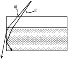
Although a caustic pattern may be appreciated to some extent inside the aquarium (because it is caused by hydrodynamics), portions of the light may also leak out of the aquarium and create an insecure pattern on the ground near the aquarium. This may be found to be a disturbing effect. It occurs when light enters the water at a steep angle to the normal to the vertical (in practice above 63 degrees from the vertical). This effect is illustrated in fig. 1, where beam 10 has a steep angle above 63 degrees from vertical in fig. 1, and beam 12 has a shallower angle below 63 degrees.
Water has a relatively low refractive index (typically n = 1.34) and this means that light at these high angles of incidence is not affected by total internal reflection at the side walls, but rather it can be refracted out of the water volume and fall to the ground. This light, which has leaked from the sides of the aquarium, can then project an uneven caustic pattern onto the floor.
Light 12 at smaller angles stays within the aquarium by total internal reflection at the sides of the aquarium.
One solution to keep all the light within the water volume is to limit the light to a beam angle well within 63 degrees with respect to the vertical, e.g. by placing a collimator on each LED. Although this directional lighting is more efficient because more light stays inside the aquarium, it also has some drawbacks. Directional lighting, in particular with a hard (hard) cut-off angle, produces a so-called fan visible as alternating bright and dark areas on the back side of the aquarium, as well as a weak illumination of the objects in the aquarium. In particular, high contrast between the top and bottom portions of the object may result, at the expense of the details of the visible shape. Furthermore, uniform illumination is believed to be beneficial to coral growth, such as the rate of growth. The directed light from above may for example cause bleaching of the bottom part of the coral, which is visible when the aquarium is viewed from the front.
US8646934 discloses an aquarium lighting system in which lenses are used to define the precise angular output from the lighting elements. US2012/326610a1 discloses a lighting unit for illuminating a habitat. The lighting unit comprises a housing and a light emitter. The light emitter includes: (i) a printed circuit board having individual light emitters, and (ii) a reflector comprising individual light guides, wherein each individual light guide surrounds a corresponding light emitter. The use of separate light guides reduces the level at which light from the separate light emitters cross each other, allowing for a more uniform light distribution.
Therefore, there is a need for an aquarium lighting solution that is efficient and versatile, e.g., allows for implementation using LEDs, and that gives minimal interference with the caustic pattern on the ground, as well as controlling the caustic pattern (e.g., frequency) in an aquarium. Fanning or dazzling shadows should also be avoided in aquariums.
Disclosure of Invention
The invention is defined by the claims.
According to an example of the lighting system proposed in the present disclosure, there is provided an aquarium lighting system comprising:
a base layer;
a set of lighting elements mounted on the base layer;
a beam shaping element associated with each lighting element, wherein the beam shaping element is for transmitting first light emitted from the lighting element at an angle to the normal below a threshold and for processing second light emitted from the lighting element at an angle to the normal above the threshold, the processing resulting in a larger amount of scattering compared to the transmitted first light.
The beam shaping element is an optical element that may, for example, surround or partially surround each lighting element, which may be an LED or a cluster of LEDs closely spaced together. Thus, one beam shaping element may be associated with a plurality of lighting elements. Each lighting element is associated with a beam shaping element, but not necessarily with a beam shaping element that is specific to that lighting element.
The beam shaping element blocks a direct view of the illumination element at an angle above a threshold, which thus functions as a cut-off angle. The light received beyond the cut-off angle is processed, for example redistributed by a light scattering element. Thus, most light having an angle less than the cut-off angle is allowed to pass through without scattering or with much less scattering than the steeper process light.
The beam processing includes a scattering function. Thus, if the reflective surface is used for scattering, it is preferably a diffuse reflector, rather than a specular reflector. In this way, the angular spread of the output light is not limited to a particular cut-off angle, but there is a cut-off angle for the direct light (i.e., it does not undergo reflection between the lighting element and the water).
The projection of the caustic pattern on the ground may be reduced or completely removed in this manner by blocking direct light at high angles. However, light at high angles is desirable to avoid fanning and weak object illumination, so the light is not completely blocked, but it is treated to increase the degree of scattering, leaving a larger virtual light source. Light at large angles to the normal will in this way come from a large virtual source and create a blurred projection that is less noticeable than a sharp caustic pattern. The direct illumination originates from a real point source. In this way, the optical function is not simply a beam limiting function, but it provides different beam processing for shallow angles compared to wide angles.
Scattering of light at high angles will also result in some of the scattered light being redirected to overlap with the direct (less scattered) light. In this way, the caustic effect within the aquarium is also reduced. In particular, the caustic effect is more dispersed there. The treatment of the secondary light thus eliminates or substantially eliminates the caustic effect outside the aquarium and also reduces the caustic effect inside the aquarium.
To further reduce the caustic effect inside the aquarium, the function of transmitting the first light may also include a diffusing (scattering) function, but with reduced scattering compared to the treatment of the second light.
The base layer may, for example, comprise a printed circuit board. The lighting elements may comprise LEDs, for example formed as an array on a printed circuit board.
The threshold value is preferably in the range of 45 to 63 degrees, for example in the range of 55 to 63 degrees, and for example in the range of 55 to 60 degrees. In this way, direct light that would escape through the side walls of the aquarium can be prevented.
In one example, the beam shaping element comprises a scattering reflector having scattering and reflecting sidewalls at opposite sides of or around the lighting element. Depending on the lighting element design, this sidewall may surround the lighting element or it may be on opposite lateral sides. The sidewall defines an aperture that subsequently forms a cut-off angle. However, after reflection on the scattering surface, the cut-off light is also projected.
The scattering reflector may have a graded sidewall that widens outwardly with increasing distance from the lighting element. Alternatively, the scattering reflector may have stepped side walls.
In another example, the beam shaping element comprises a plate with a patterned diffuser having openings in the diffuser pattern for transmitting the first light. The opening defines a cut-off angle, and light provided to the opening is transmitted without diffusion.
In another example, the beam shaping element comprises a patterned light guide having patterned openings in the light guide for transmitting the first light. Light having an angle steeper than the threshold is transmitted into the light guide and may then be emitted, for example, in substantially random positions and directions.
The first light may be transmitted without optical processing at all. However, the beam shaping element may instead comprise a scattering element for scattering said first light, which has a smaller amount of scattering than the processing of the second light. The (reduced amount of) scattering of the first light reduces the effect of the caustic pattern inside the aquarium.
The present disclosure also provides an aquarium comprising a water container and a lighting system as defined above. The lighting system may project light concentrated in a vertically downward direction to the water below. The lighting system may be distributed over an area similar to the area of the water container to provide illumination of the entire water volume of the aquarium. In use, the lighting system may be positioned, for example, 10 to 25cm above the water surface.
The present disclosure also provides a method of illuminating an aquarium comprising:
providing a light output from a set of lighting elements mounted above the water of the aquarium;
transmitting first light emitted from the lighting element at an angle below a threshold from normal; and
the processing of the second light emitted from the lighting element at an angle above the threshold with respect to the normal results in a larger amount of scattering compared to the transmitted first light.
The threshold value is for example in the range of 45 to 63 degrees, more preferably in the range of 55 to 63 degrees, even more preferably in the range of 55 to 60 degrees.
Drawings
Examples will now be described in detail with reference to the accompanying drawings, in which:
FIG. 1 shows how light at certain angles can escape through the side walls of an aquarium;
FIG. 2 shows an aquarium with a lighting system;
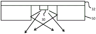
fig. 3 shows a lighting element without beam shaping at the output;
figure 4 shows a first example of a beam shaping system;
fig. 5 shows a second example of a beam shaping system;
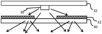
fig. 6 shows a third example of a beam shaping system;
fig. 7 shows a fourth example of a beam shaping system;
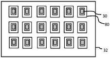
fig. 8 shows a first example of a lighting system; and
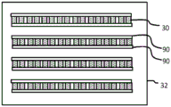
fig. 9 shows a second example of a lighting system.
Detailed Description
The present disclosure provides an aquarium lighting system having a set of lighting elements, each lighting element associated with a beam shaping element for transmitting first light emitted from the lighting element at an angle below a threshold from normal. The beam shaping element processes the second light emitted from the illumination element at an angle above a threshold to the normal. This process gives a greater amount of scattering compared to the transmitted light, avoiding direct light at steep angles.
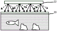
Fig. 2 shows an aquarium including a water vessel 20 having a lighting system 22 suspended above the water. The lighting system projects light substantially downward into the water below. The lighting system is sized to provide illumination to the entire water volume of the aquarium. The lighting system may for example be positioned 10 to 30cm above the water surface.
Light directed downward close to the vertical (shown as a solid line) is provided without any significant beam shaping or scattering. The illumination system preferably comprises an array of LEDs, and light at these shallow angles to the vertical appears as an array of point sources. This light is captured by total internal reflection at the side walls of the aquarium and it can create a caustic pattern at the base of the aquarium. Light directed downward away from the vertical (shown as a dashed line) undergoes scattering. Light at these steeper angles from the vertical appears to originate from a large area source as a result of scattering. Light that remains at a steep angle after scattering can escape through the aquarium side wall, but for this light the caustic pattern effect is reduced. By allowing light at steep angles (but effecting beam shaping to increase scattering), the quality of illumination within the aquarium is maintained.
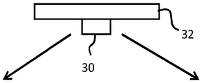
Fig. 3 shows an LED provided over a base layer, such as a printed circuit board, without beam shaping. The LED appears as a point source and emits light over a wide range of angles, for example 80 degrees on each side of the normal.
The present disclosure provides a set of such lighting elements, and it has a beam shaping element associated with each lighting element.
The beam shaping element is for transmitting first light emitted from the lighting element at an angle to the normal below a threshold value, and for processing second light emitted from the lighting element at an angle to the normal above the threshold value, the processing resulting in a larger amount of scattering compared to the transmitted first light.
The beam shaping element is an optical element that may, for example, surround or partially surround its associated lighting element. The threshold angle acts as a cut-off angle for the light that has been transmitted, but light beyond the cut-off angle is also emitted, but after some light redistribution. Thus, most light having an angle less than the cut-off angle is allowed to pass through without scattering or with much less scattering than steeper process light.
Fig. 4-7 show examples of different beam shaping elements for individual LEDs.
In all cases, the beam shaping element will be designed taking into account the shape of the lighting element. For example, for a point-like source such as an individual LED or for a cluster of LEDs, the beam shaping element is a rotationally symmetric element arranged around the LED or cluster of LEDs. For a linear source, such as a row of closely spaced LEDs, the beam shaping element may also be linear. In this case, the beam shaping element may comprise a strip on each lateral side of the linear light source. The cut-off angle is then only needed in the lateral direction (perpendicular to the row direction). For other distributions of light sources, the geometry of the beam shaping element is designed to match the distribution of the light sources. For example, for a circular or polygonal shape of the light source, the beam shaping element has a corresponding shape.
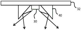
Fig. 4 shows a first example, in which a white reflector 40 is placed around the associated LED (or along the edge of the LED row). The direct view of the LED is blocked outside a certain angle and this light is redistributed by diffuse (diffuse) reflection. Fig. 4 shows a beam shaping element with a graded profile, which widens outwards with increasing distance from the LED 30. The tapered sides can be used to redirect much of the light at steep angles to be directed in a more downward direction, although scattering means that some light will still be emitted at large angles to the normal. Alternatively, the scattering reflector 50 may have stepped side walls, as shown in the second example of fig. 5. In this case, the steep angle light undergoes scattering rather than being otherwise directed in a vertically downward direction as in the example of fig. 4.
Fig. 6 shows a third example, where the direct view of the LEDs 30 is blocked by using a transparent cover plate 60 with patterned scattering elements 62 (the patterned scattering elements may be on the LED side or on the opposite side of the cover plate). The pattern defines an opening aligned with the LED. For light having an angle smaller than the cut-off angle, the plate is transparent (or only very lightly scattering) at the opening, while at larger angles further away from the LED the scattering is stronger. The transition between low and high amount scattering is preferably soft to avoid strong cut-off effects.
The scattering element may be reflective and/or transmissive and may be realized by, for example, using a coating with paint dots (paint dots) of varying density or size, a surface treatment (e.g. surface roughness), or a variation of the scattering particle density within the bulk of the material.
Fig. 7 shows a fourth example, in which the cut-off is created by a light-guiding element 70. The light guide element has an opening aligned with the LED so that steep light can enter the light guide at the side faces (which are in the normal direction). Above the cut-off angle, the light enters this side and is then captured by the light guide 70. It is subsequently coupled out of the light guide via the scattering elements or surfaces. At either side of the light guide, the scattering element may again be reflective or transmissive, and it may have a varying scattering intensity depending on the position. For example, a scattering surface pattern may be applied to the outer surface at the bottom of the light guide 70.
The angular threshold between zero or low scattering and higher scattering is for example in the range of 45 to 63 degrees, more preferably in the range of 55 to 63 degrees, and even more preferably in the range of 55 to 60 degrees.
In all the examples above, the first light is transmitted without optical processing at all. However, the beam shaping element may instead comprise a scattering element for scattering the first (directional) light, which has a smaller amount of scattering than the processing of the second light. This may include a light scattering diffuser plate mounted over the side walls (fig. 4 and 5), or a portion of reduced scattering in the window (fig. 6) or a light scattering diffuser plate mounted over the light guide (fig. 7).
The illumination diffuser plate may be transparent outside the central window, or else a uniform illumination diffuser plate may cover the entire illumination device. In this case, there are two scattering mechanisms arranged in series for high angle light, but only a single scattering element for low angle, central light. This central light thus remains more directional than the more angular light. The scattering of the first light reduces the effect of the caustic pattern within the aquarium by reducing the directionality of the light entering the aquarium.
As mentioned above, the lighting elements may be formed individually or in groups.
Fig. 8 shows an array of LEDs formed on a two-dimensional printed circuit board 32, and each having a surrounding beam shaping element 80. Fig. 9 shows an LED array formed on a two-dimensional area, and LEDs formed in rows. Each row has beam shaping elements 90 to each lateral side.
A number of different beam shaping elements have been described above. The illumination system may combine different types of beam shaping elements into one product.
Other variations to the disclosed embodiments can be understood and effected by those skilled in the art in practicing the claimed invention, from a study of the drawings, the disclosure, and the appended claims. In the claims, the word "comprising" does not exclude other elements or steps, and the indefinite article "a" or "an" does not exclude a plurality. The mere fact that certain measures are recited in mutually different dependent claims does not indicate that a combination of these measures cannot be used to advantage. Any reference signs in the claims shall not be construed as limiting the scope.
Claims (15)
1. An aquarium lighting system comprising:
a base layer (32);
a set of lighting elements (30) mounted on the substrate;
a beam shaping element (40, 50,60,70,80, 90) associated with each lighting element, wherein the beam shaping element is for transmitting first light emitted from the lighting element (30) at an angle to the normal below a threshold and for processing second light emitted from the lighting element at an angle to the normal above the threshold, the processing resulting in a larger amount of scattering of the second light than the transmitted first light,
wherein the beam shaping element comprises a plate (60) with a patterned diffuser (62) having openings in the diffusing pattern for transmitting the first light, or
Wherein the beam shaping element comprises a patterned light guide (70) having patterned openings in the light guide for transmitting the first light for capturing and subsequently re-emitting the second light into and from the light guide.
2. The system of claim 1, wherein the base layer (32) comprises a printed circuit board.
3. The system of claim 1 or 2, wherein each of the lighting elements (30) comprises an LED.
4. The system of claim 1 or 2, wherein the lighting elements are arranged in a geometric distribution on the base layer, and wherein the beam shaping elements are designed to match said geometric distribution of the lighting elements on the base layer.
5. The system of claim 4, wherein the geometric distribution of lighting elements in the base layer is linear, circular, or polygonal.
6. The system of any one of claims 1, 2, 5, wherein the threshold is in the range of 45 to 63 degrees.
7. The system of claim 6, wherein the threshold is in the range of 55 to 63 degrees.
8. The system of claim 7, wherein the threshold is in the range of 55 to 60 degrees.
9. The system of any of claims 1, 2, 5, 7, 8, wherein the beam shaping element further comprises a scattering element for scattering the first light, having a smaller amount of scattering than the scattering provided by the processing of the second light.
10. An aquarium comprising a water container (20) and a lighting system (22) as claimed in any preceding claim for hanging over the water container.
11. An aquarium as claimed in claim 10 wherein, in use, the lighting system (22) is positioned 10 to 30cm above the water surface.
12. A method of illuminating an aquarium comprising:
providing a light output from a set of lighting elements mounted above the water of the aquarium;
transmitting first light emitted from the lighting element at an angle below a threshold from normal; and
processing the second light emitted from the lighting element at an angle above a threshold to the normal by means of a plate (60) with a patterned diffuser (62) having openings in the diffuser pattern for transmitting the first light or a patterned light guide (70) capturing the second light into the light guide and subsequently re-emitting the second light from the light guide, the patterned light guide having patterned openings in the light guide for transmitting the first light, the processing resulting in a greater amount of scattering compared to the transmitted first light.
13. The method of claim 12, wherein the threshold is in the range of 45 to 63 degrees.
14. The method of claim 13, wherein the threshold is in the range of 55 to 63 degrees.
15. The method of claim 14, wherein the threshold is in the range of 55 to 60 degrees.
Applications Claiming Priority (3)
| Application Number | Priority Date | Filing Date | Title |
|---|---|---|---|
| EP15154864.1 | 2015-02-12 | ||
| EP15154864 | 2015-02-12 | ||
| PCT/EP2016/052919 WO2016128514A1 (en) | 2015-02-12 | 2016-02-11 | Aquarium lighting |
Publications (2)
| Publication Number | Publication Date |
|---|---|
| CN107205367A CN107205367A (en) | 2017-09-26 |
| CN107205367B true CN107205367B (en) | 2021-07-06 |
Family
ID=52465288
Family Applications (1)
| Application Number | Title | Priority Date | Filing Date |
|---|---|---|---|
| CN201680009984.7A Active CN107205367B (en) | 2015-02-12 | 2016-02-11 | Aquarium lighting |
Country Status (7)
| Country | Link |
|---|---|
| US (1) | US10595514B2 (en) |
| EP (1) | EP3255983B1 (en) |
| JP (1) | JP7027167B2 (en) |
| CN (1) | CN107205367B (en) |
| ES (1) | ES2871072T3 (en) |
| PL (1) | PL3255983T3 (en) |
| WO (1) | WO2016128514A1 (en) |
Families Citing this family (6)
| Publication number | Priority date | Publication date | Assignee | Title |
|---|---|---|---|---|
| KR102704441B1 (en) * | 2016-11-25 | 2024-09-09 | 삼성디스플레이 주식회사 | mask for deposition, manufacturing method thereof, manufacturing apparatus of display apparatus and manufacturing method of display apparatus |
| US20190191674A1 (en) * | 2017-12-21 | 2019-06-27 | Antonio Manuel Rodriguez Perez | Lamp and Fish Tank Combination Assembly |
| CN108288819B (en) * | 2018-03-02 | 2024-06-14 | 佛山市国星光电股份有限公司 | VCSEL device |
| ES2950812T3 (en) * | 2019-08-27 | 2023-10-13 | Signify Holding Bv | Lighting device to illuminate an aquarium |
| US11751546B2 (en) * | 2021-04-21 | 2023-09-12 | Ariel Negron | Multi-directional modular aquarium LED lighting bulbs and system |
| US20240053618A1 (en) * | 2022-08-15 | 2024-02-15 | Martineau & Associates | Container system for monitoring and imaging aquatic organisms |
Citations (5)
| Publication number | Priority date | Publication date | Assignee | Title |
|---|---|---|---|---|
| CN101067479A (en) * | 2007-02-06 | 2007-11-07 | 宁波安迪光电科技有限公司 | Large power LED illuminating device |
| JP2012022272A (en) * | 2010-07-16 | 2012-02-02 | Asahi Kasei Corp | Light diffusion sheet and light source unit |
| WO2013111717A1 (en) * | 2012-01-24 | 2013-08-01 | 日東電工株式会社 | Foam diffuse reflector |
| CN103292251A (en) * | 2013-06-25 | 2013-09-11 | 苏州科利亚照明科技有限公司 | Kicker-light water tank ornamental lamp |
| JP2014521202A (en) * | 2011-07-20 | 2014-08-25 | コーニンクレッカ フィリップス エヌ ヴェ | Lighting elements, lighting systems, and luminaries that provide a skylight appearance |
Family Cites Families (19)
| Publication number | Priority date | Publication date | Assignee | Title |
|---|---|---|---|---|
| US20030137829A1 (en) | 2002-01-24 | 2003-07-24 | Ayers Bryan Keith | Shimmerlight aquarium illuminator |
| EP2041487A2 (en) | 2006-07-11 | 2009-04-01 | Koninklijke Philips Electronics N.V. | Transparent body comprising at least one embedded led |
| JP2010246486A (en) * | 2009-04-17 | 2010-11-04 | Colcoat Kk | Device for illuminating aquarium |
| US8585253B2 (en) | 2009-08-20 | 2013-11-19 | Illumitex, Inc. | System and method for color mixing lens array |
| CN201575367U (en) * | 2009-10-28 | 2010-09-08 | 柏友照明科技股份有限公司 | Lighting device of aquarium |
| JP3162698U (en) * | 2010-03-12 | 2010-09-16 | 友吉 金城 | Ornamental lighting fixture and aquarium fish tank using the same |
| RU2569325C2 (en) * | 2010-04-09 | 2015-11-20 | Конинклейке Филипс Электроникс Н.В. | Lighting device having smooth cut-off |
| US8646934B2 (en) | 2010-04-14 | 2014-02-11 | Cogent Designs, Inc. | Aquarium light strip |
| US8657463B2 (en) * | 2010-07-01 | 2014-02-25 | Jan Flemming Samuel Lichten | Lighting fixture for a poultry house |
| US8568009B2 (en) * | 2010-08-20 | 2013-10-29 | Dicon Fiberoptics Inc. | Compact high brightness LED aquarium light apparatus, using an extended point source LED array with light emitting diodes |
| JP5178796B2 (en) * | 2010-09-10 | 2013-04-10 | 三菱電機株式会社 | Light emitting device and lighting device |
| WO2012178035A2 (en) * | 2011-06-22 | 2012-12-27 | Ecotech Marine, Llc | Lighting unit and method of controlling |
| US20130033851A1 (en) * | 2011-08-07 | 2013-02-07 | Yu-Chin Wang | Aquarium led lighting device |
| US9374985B2 (en) * | 2011-12-14 | 2016-06-28 | Once Innovations, Inc. | Method of manufacturing of a light emitting system with adjustable watt equivalence |
| US9016240B2 (en) * | 2011-12-21 | 2015-04-28 | Juliette DELABBIO | Method and system for enhancing growth and survivability of aquatic organisms |
| CN203010491U (en) * | 2012-11-27 | 2013-06-19 | 杭州科凡照明电器有限公司 | LED (light emitting diode) lamp shade |
| US10231304B2 (en) * | 2013-02-20 | 2019-03-12 | Current USA, Inc. | Habitat control system |
| CN104266092B (en) * | 2014-09-05 | 2016-05-25 | 中山市晔汇电子有限公司 | A kind of water-proof LED lamp and preparation method thereof |
| US10247191B2 (en) * | 2016-12-28 | 2019-04-02 | WLC Enterprises, Inc. | Combined LED light and fan apparatus |
-
2016
- 2016-02-11 WO PCT/EP2016/052919 patent/WO2016128514A1/en active Application Filing
- 2016-02-11 US US15/550,413 patent/US10595514B2/en active Active
- 2016-02-11 PL PL16704597T patent/PL3255983T3/en unknown
- 2016-02-11 JP JP2017541925A patent/JP7027167B2/en active Active
- 2016-02-11 CN CN201680009984.7A patent/CN107205367B/en active Active
- 2016-02-11 ES ES16704597T patent/ES2871072T3/en active Active
- 2016-02-11 EP EP16704597.0A patent/EP3255983B1/en active Active
Patent Citations (5)
| Publication number | Priority date | Publication date | Assignee | Title |
|---|---|---|---|---|
| CN101067479A (en) * | 2007-02-06 | 2007-11-07 | 宁波安迪光电科技有限公司 | Large power LED illuminating device |
| JP2012022272A (en) * | 2010-07-16 | 2012-02-02 | Asahi Kasei Corp | Light diffusion sheet and light source unit |
| JP2014521202A (en) * | 2011-07-20 | 2014-08-25 | コーニンクレッカ フィリップス エヌ ヴェ | Lighting elements, lighting systems, and luminaries that provide a skylight appearance |
| WO2013111717A1 (en) * | 2012-01-24 | 2013-08-01 | 日東電工株式会社 | Foam diffuse reflector |
| CN103292251A (en) * | 2013-06-25 | 2013-09-11 | 苏州科利亚照明科技有限公司 | Kicker-light water tank ornamental lamp |
Also Published As
| Publication number | Publication date |
|---|---|
| CN107205367A (en) | 2017-09-26 |
| JP2018505535A (en) | 2018-02-22 |
| US10595514B2 (en) | 2020-03-24 |
| EP3255983B1 (en) | 2021-04-07 |
| US20180027779A1 (en) | 2018-02-01 |
| PL3255983T3 (en) | 2021-10-25 |
| WO2016128514A1 (en) | 2016-08-18 |
| EP3255983A1 (en) | 2017-12-20 |
| ES2871072T3 (en) | 2021-10-28 |
| JP7027167B2 (en) | 2022-03-01 |
Similar Documents
| Publication | Publication Date | Title |
|---|---|---|
| CN107205367B (en) | Aquarium lighting | |
| EP3434966B1 (en) | Vehicle lamp and vehicle provided with it | |
| EP3396233B1 (en) | Backlight device and liquid crystal display apparatus | |
| KR20190003115U (en) | Light guide device | |
| EP3152482B1 (en) | Wall wash lighting system | |
| US10697611B2 (en) | Non-circular optic for distributing light | |
| CN105745489B (en) | Lighting unit | |
| JP6274974B2 (en) | Luminous flux control member, light emitting device, and illumination device | |
| KR20170033932A (en) | Optical device and lighting apparatus including the same | |
| JP6793494B2 (en) | Vehicle lighting | |
| WO2015005424A1 (en) | Optical element and illumination device including optical element | |
| JP6418425B2 (en) | Lamp cover optical device | |
| JP2016045407A (en) | Light flux control member, light emitting device and illumination device | |
| CN104989986B (en) | A kind of anti-dazzle LED applied to Sports lighting | |
| JP6033634B2 (en) | Surface illumination light emitting device | |
| KR101824688B1 (en) | Diffuser cover for led and light apparatus including the same | |
| JP2018036407A (en) | Luminous flux control member, light emitting device, surface light source device, and display device | |
| JP2009259448A (en) | Lighting module, light source unit, and luminaire | |
| JP6345539B2 (en) | Luminous flux control member and light emitting device | |
| KR101681496B1 (en) | Glare Control Possible LED Lens Holder | |
| CN114258266A (en) | Lighting device for illuminating aquarium | |
| KR20190036596A (en) | Fish gathering lamp | |
| KR20110060473A (en) | Lighting device and optical plate | |
| CN104456162A (en) | Lighting lamp and lighting optical module thereof | |
| JP2015153522A (en) | Light guide plate and luminaire |
Legal Events
| Date | Code | Title | Description |
|---|---|---|---|
| PB01 | Publication | ||
| PB01 | Publication | ||
| SE01 | Entry into force of request for substantive examination | ||
| SE01 | Entry into force of request for substantive examination | ||
| CB02 | Change of applicant information |
Address after: Eindhoven Applicant after: Signify Holdings Ltd. Address before: Eindhoven Applicant before: Philips Lighting Holdings |
|
| CB02 | Change of applicant information | ||
| GR01 | Patent grant | ||
| GR01 | Patent grant |