CN107197137B - Image processing apparatus, image processing method, and recording medium - Google Patents
Image processing apparatus, image processing method, and recording medium Download PDFInfo
- Publication number
- CN107197137B CN107197137B CN201710133203.1A CN201710133203A CN107197137B CN 107197137 B CN107197137 B CN 107197137B CN 201710133203 A CN201710133203 A CN 201710133203A CN 107197137 B CN107197137 B CN 107197137B
- Authority
- CN
- China
- Prior art keywords
- region
- posture
- image
- unit
- captured image
- Prior art date
- Legal status (The legal status is an assumption and is not a legal conclusion. Google has not performed a legal analysis and makes no representation as to the accuracy of the status listed.)
- Active
Links
- 238000012545 processing Methods 0.000 title claims abstract description 149
- 238000003672 processing method Methods 0.000 title claims abstract description 7
- 238000003384 imaging method Methods 0.000 claims abstract description 73
- 238000000034 method Methods 0.000 claims abstract description 64
- 230000008569 process Effects 0.000 claims abstract description 62
- 230000003287 optical effect Effects 0.000 claims description 18
- 238000001514 detection method Methods 0.000 claims description 8
- 230000005484 gravity Effects 0.000 claims description 6
- 230000036544 posture Effects 0.000 description 110
- 238000010586 diagram Methods 0.000 description 22
- 238000004891 communication Methods 0.000 description 12
- 238000011161 development Methods 0.000 description 8
- 238000007906 compression Methods 0.000 description 7
- 230000002093 peripheral effect Effects 0.000 description 6
- 230000006835 compression Effects 0.000 description 5
- 230000001133 acceleration Effects 0.000 description 4
- 238000012937 correction Methods 0.000 description 4
- 238000012986 modification Methods 0.000 description 4
- 230000004048 modification Effects 0.000 description 4
- 230000000694 effects Effects 0.000 description 3
- 230000006870 function Effects 0.000 description 3
- 230000005540 biological transmission Effects 0.000 description 2
- 230000008859 change Effects 0.000 description 2
- 238000009966 trimming Methods 0.000 description 2
- 238000012790 confirmation Methods 0.000 description 1
- 238000010030 laminating Methods 0.000 description 1
- 239000004973 liquid crystal related substance Substances 0.000 description 1
Images


Classifications
-
- H—ELECTRICITY
- H04—ELECTRIC COMMUNICATION TECHNIQUE
- H04N—PICTORIAL COMMUNICATION, e.g. TELEVISION
- H04N23/00—Cameras or camera modules comprising electronic image sensors; Control thereof
- H04N23/60—Control of cameras or camera modules
- H04N23/62—Control of parameters via user interfaces
-
- H—ELECTRICITY
- H04—ELECTRIC COMMUNICATION TECHNIQUE
- H04N—PICTORIAL COMMUNICATION, e.g. TELEVISION
- H04N5/00—Details of television systems
- H04N5/222—Studio circuitry; Studio devices; Studio equipment
- H04N5/262—Studio circuits, e.g. for mixing, switching-over, change of character of image, other special effects ; Cameras specially adapted for the electronic generation of special effects
- H04N5/2628—Alteration of picture size, shape, position or orientation, e.g. zooming, rotation, rolling, perspective, translation
-
- G—PHYSICS
- G06—COMPUTING; CALCULATING OR COUNTING
- G06F—ELECTRIC DIGITAL DATA PROCESSING
- G06F18/00—Pattern recognition
- G06F18/20—Analysing
- G06F18/24—Classification techniques
-
- G06T5/80—
-
- G—PHYSICS
- G06—COMPUTING; CALCULATING OR COUNTING
- G06T—IMAGE DATA PROCESSING OR GENERATION, IN GENERAL
- G06T7/00—Image analysis
- G06T7/10—Segmentation; Edge detection
- G06T7/11—Region-based segmentation
-
- G—PHYSICS
- G06—COMPUTING; CALCULATING OR COUNTING
- G06T—IMAGE DATA PROCESSING OR GENERATION, IN GENERAL
- G06T7/00—Image analysis
- G06T7/10—Segmentation; Edge detection
- G06T7/13—Edge detection
-
- G—PHYSICS
- G06—COMPUTING; CALCULATING OR COUNTING
- G06T—IMAGE DATA PROCESSING OR GENERATION, IN GENERAL
- G06T7/00—Image analysis
- G06T7/60—Analysis of geometric attributes
-
- G—PHYSICS
- G06—COMPUTING; CALCULATING OR COUNTING
- G06T—IMAGE DATA PROCESSING OR GENERATION, IN GENERAL
- G06T7/00—Image analysis
- G06T7/70—Determining position or orientation of objects or cameras
-
- G—PHYSICS
- G06—COMPUTING; CALCULATING OR COUNTING
- G06V—IMAGE OR VIDEO RECOGNITION OR UNDERSTANDING
- G06V10/00—Arrangements for image or video recognition or understanding
- G06V10/10—Image acquisition
- G06V10/12—Details of acquisition arrangements; Constructional details thereof
- G06V10/14—Optical characteristics of the device performing the acquisition or on the illumination arrangements
- G06V10/147—Details of sensors, e.g. sensor lenses
-
- G—PHYSICS
- G06—COMPUTING; CALCULATING OR COUNTING
- G06V—IMAGE OR VIDEO RECOGNITION OR UNDERSTANDING
- G06V10/00—Arrangements for image or video recognition or understanding
- G06V10/20—Image preprocessing
- G06V10/22—Image preprocessing by selection of a specific region containing or referencing a pattern; Locating or processing of specific regions to guide the detection or recognition
- G06V10/225—Image preprocessing by selection of a specific region containing or referencing a pattern; Locating or processing of specific regions to guide the detection or recognition based on a marking or identifier characterising the area
-
- G—PHYSICS
- G06—COMPUTING; CALCULATING OR COUNTING
- G06V—IMAGE OR VIDEO RECOGNITION OR UNDERSTANDING
- G06V10/00—Arrangements for image or video recognition or understanding
- G06V10/20—Image preprocessing
- G06V10/24—Aligning, centring, orientation detection or correction of the image
- G06V10/243—Aligning, centring, orientation detection or correction of the image by compensating for image skew or non-uniform image deformations
-
- G—PHYSICS
- G06—COMPUTING; CALCULATING OR COUNTING
- G06V—IMAGE OR VIDEO RECOGNITION OR UNDERSTANDING
- G06V40/00—Recognition of biometric, human-related or animal-related patterns in image or video data
- G06V40/10—Human or animal bodies, e.g. vehicle occupants or pedestrians; Body parts, e.g. hands
- G06V40/16—Human faces, e.g. facial parts, sketches or expressions
- G06V40/161—Detection; Localisation; Normalisation
- G06V40/166—Detection; Localisation; Normalisation using acquisition arrangements
-
- H—ELECTRICITY
- H04—ELECTRIC COMMUNICATION TECHNIQUE
- H04N—PICTORIAL COMMUNICATION, e.g. TELEVISION
- H04N23/00—Cameras or camera modules comprising electronic image sensors; Control thereof
- H04N23/60—Control of cameras or camera modules
- H04N23/63—Control of cameras or camera modules by using electronic viewfinders
- H04N23/631—Graphical user interfaces [GUI] specially adapted for controlling image capture or setting capture parameters
- H04N23/632—Graphical user interfaces [GUI] specially adapted for controlling image capture or setting capture parameters for displaying or modifying preview images prior to image capturing, e.g. variety of image resolutions or capturing parameters
-
- H—ELECTRICITY
- H04—ELECTRIC COMMUNICATION TECHNIQUE
- H04N—PICTORIAL COMMUNICATION, e.g. TELEVISION
- H04N23/00—Cameras or camera modules comprising electronic image sensors; Control thereof
- H04N23/60—Control of cameras or camera modules
- H04N23/66—Remote control of cameras or camera parts, e.g. by remote control devices
-
- H—ELECTRICITY
- H04—ELECTRIC COMMUNICATION TECHNIQUE
- H04N—PICTORIAL COMMUNICATION, e.g. TELEVISION
- H04N23/00—Cameras or camera modules comprising electronic image sensors; Control thereof
- H04N23/60—Control of cameras or camera modules
- H04N23/667—Camera operation mode switching, e.g. between still and video, sport and normal or high- and low-resolution modes
-
- H—ELECTRICITY
- H04—ELECTRIC COMMUNICATION TECHNIQUE
- H04N—PICTORIAL COMMUNICATION, e.g. TELEVISION
- H04N23/00—Cameras or camera modules comprising electronic image sensors; Control thereof
- H04N23/60—Control of cameras or camera modules
- H04N23/698—Control of cameras or camera modules for achieving an enlarged field of view, e.g. panoramic image capture
-
- H—ELECTRICITY
- H04—ELECTRIC COMMUNICATION TECHNIQUE
- H04N—PICTORIAL COMMUNICATION, e.g. TELEVISION
- H04N23/00—Cameras or camera modules comprising electronic image sensors; Control thereof
- H04N23/80—Camera processing pipelines; Components thereof
-
- G—PHYSICS
- G06—COMPUTING; CALCULATING OR COUNTING
- G06T—IMAGE DATA PROCESSING OR GENERATION, IN GENERAL
- G06T2207/00—Indexing scheme for image analysis or image enhancement
- G06T2207/30—Subject of image; Context of image processing
- G06T2207/30244—Camera pose
Abstract
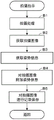
The invention provides an image processing apparatus, an image processing method and a recording medium. A digital camera is provided with an imaging device (10) and a main device (20), wherein when a region of a captured image acquired from the imaging device (10) that is not along the edge portion of the periphery of the captured image is defined as a1 st region, a region including the edge portion is defined as a2 nd region, and a predetermined process is performed on either the 1 st region or the 2 nd region, the main device (20) determines whether the 1 st region is the target of the predetermined process or the 2 nd region is the target of the predetermined process based on the orientation of the imaging device (10).
Description
The application claims 2016 priority from Japanese patent application 2016, 049151, filed 3, 14, 2016 and is hereby incorporated by reference in its entirety, including the specification, claims, drawings, and abstract.
Technical Field
The present invention relates to an image processing apparatus, an image processing method, and a recording medium for processing a captured image.
Background
In general, in an imaging apparatus such as a digital camera, when a desired object is emphasized more than a background at the time of imaging, the object is positioned in the center (central portion) of a captured image, and when a desired object is emphasized and a background is also emphasized at the time of imaging, the desired object and the background are uniformly arranged in the entire captured image. However, in order to obtain a new image (an image with a narrowed angle of view) by further performing close-up on only a desired subject from among the captured images, it is necessary to find a desired captured image from among many saved images (captured images) and designate a part of the captured image as a cut range by the user. At this time, for example, as disclosed in japanese patent application laid-open No. 2000-106623, if the shape of the clipping range is rectangular, the user is allowed to specify positions on the screen corresponding to the four corners thereof.
Disclosure of Invention
Problems to be solved by the invention
However, each time a desired captured image is found from among many stored images (captured images) and the range of capturing thereof is specified, four corners are specified, which not only increases the number of specifying errors but also imposes a large burden on the user.
This is not limited to the case where a part of the captured image is cut out, and the same is true when other processing is performed, for example, processing for correcting distortion of a wide-angle image, and image processing for performing special effects such as contrast, blur, and sharpness.
The present invention addresses the problem of being able to easily and appropriately identify a region in a captured image in which processing is to be executed.
Means for solving the problems
An image processing apparatus according to the present invention is characterized by comprising: a processing unit that takes, as a1 st region, a region of the captured image acquired by the capturing unit that is not along an edge portion of the periphery of the captured image, and takes, as a2 nd region, a region including the edge portion, and performs a predetermined process on either of the 1 st region and the 2 nd region; and a determination unit that determines whether to take the 1 st region as a subject of the given processing or to take the 2 nd region as a subject of the given processing, based on posture information when the photographing unit acquires the photographed image.
An image processing method according to the present invention is an image processing method in an image processing apparatus, including: a step of setting, as a1 st region, a region that is not along an edge portion around the captured image in the captured image acquired by the capturing unit, and setting, as a2 nd region, a region including the edge portion, and performing a predetermined process on either one of the 1 st region and the 2 nd region; and a step of determining whether to take the 1 st region as a subject of the given processing or the 2 nd region as a subject of the given processing, based on posture information when the photographing unit acquires the photographed image.
A computer-readable recording medium of the present invention stores a program for causing a computer of an image processing apparatus to realize a function of setting an area of a captured image acquired by an imaging unit, the area not being along an edge portion of a periphery of the captured image, as a1 st area, setting an area including the edge portion, as a2 nd area, and performing a predetermined process on either the 1 st area or the 2 nd area, and determining whether to set the 1 st area as a target of the predetermined process or set the 2 nd area as a target of the predetermined process based on posture information at the time of acquiring the captured image by the imaging unit.
Effects of the invention
According to the present invention, the region in the captured image where processing is performed can be easily and appropriately determined.
Drawings
The accompanying drawings, which are incorporated in and constitute a part of this specification, illustrate embodiments of the invention and, together with a general description of the invention given above, and the detailed description of the embodiments given below, serve to explain the principles of the invention.
Fig. 1A is an external view showing a digital camera used as an image processing apparatus, in which an image pickup apparatus 10 and a main body apparatus 20 constituting the camera are integrally combined.
Fig. 1B is an external view showing a state in which the imaging device 10 and the main body device 20 are separated.
Fig. 2A is a block diagram showing a schematic configuration of the imaging apparatus 10.
Fig. 2B is a block diagram showing a schematic configuration of the main apparatus 20.
Fig. 3A is a diagram illustrating a case where the imaging apparatus 10 is set to the 1 st posture.
Fig. 3B is a diagram illustrating a fisheye image captured by the fisheye lens with the imaging apparatus 10 set to the 1 st posture.
Fig. 3C is a diagram illustrating a case where the imaging apparatus 10 is set to the 2 nd posture.
Fig. 3D is a diagram illustrating a fisheye image captured by the fisheye lens with the imaging device 10 in the 2 nd posture.
Fig. 4A to 4F are diagrams illustrating a case where the housing of the imaging apparatus 10 is further rotated around the optical axis while maintaining the 1 st posture and the direction thereof is changed, and an image captured in the posture.
Fig. 5 is a flowchart for explaining the operation of the main apparatus 20 (the characteristic operation of embodiment 1) that is started when the imaging mode is switched.
Fig. 6 is a flow chart following the actions of fig. 5.
Fig. 7A is a block diagram showing a schematic configuration of an image processing apparatus (personal computer: PC)30 according to embodiment 2.
Fig. 7B is a block diagram showing a schematic configuration of an imaging device (digital camera) 40 according to embodiment 2.
Fig. 8A is a diagram illustrating a fisheye image captured in the 1 st posture in embodiment 2.
Fig. 8B is a diagram illustrating an image obtained by correcting distortion of the standard-size expanded image cut out from the 1 st region of the fisheye image in embodiment 2.
Fig. 9A is a diagram illustrating a fisheye image captured in the 2 nd posture in embodiment 2.
Fig. 9B is a view illustrating an image obtained by correcting distortion of an image for panoramic size expansion cut out from the 2 nd region of the fisheye image in embodiment 2.
Fig. 10 is a flowchart showing an operation (a characteristic operation of embodiment 2) to be started in the camera 40 in accordance with the shooting instruction operation.
Fig. 11 is a flowchart showing an operation (a characteristic operation of embodiment 2) when an image is displayed on the PC 30.
Detailed Description
Hereinafter, embodiments of the present invention will be described in detail with reference to the drawings.
(embodiment 1)
First, embodiment 1 of the present invention will be described with reference to fig. 1 to 6.
This embodiment exemplifies a case where the present invention is applied to a digital camera as an image processing apparatus, and the camera is a separate type digital camera which can be separated into an imaging apparatus 10 having an imaging unit described later and a main apparatus 20 having a display unit described later. Fig. 1 is an external view of an image processing apparatus (digital camera), fig. 1A shows a state in which an image pickup apparatus 10 and a main apparatus 20 are integrally combined, and fig. 1B shows a state in which the image pickup apparatus 10 and the main apparatus 20 are separated. The entire housing of the imaging device 10 is box-shaped. In the figure, 10a shows a connection portion with the main body device 20 provided at one end portion of the imaging device 10.
The imaging device 10 and the main device 20 constituting the separate digital camera can be paired (wireless connection identification) using wireless communication available for each, and wireless communication is, for example, wireless LAN (Wi-Fi) or Bluetooth (registered trademark). The image captured on the imaging device 10 side is received and acquired on the main device 20 side. And displays the captured image as a live view image. In the present embodiment, the captured image is not limited to the stored image, and is a broad image including an image displayed on the live view screen (live view image: image before storage).
Fig. 2A is a block diagram showing the structure of the image pickup apparatus 10, and fig. 2B is a block diagram showing the structure of the main apparatus 20.
In fig. 2A, the imaging device 10 can capture a moving image in addition to a still image, and includes a control unit 11, a power supply unit 12, a storage unit 13, a communication unit 14, an operation unit 15, an imaging unit 16, and an attitude detection unit 17. The control unit 11 operates by power supply from a power supply unit (secondary battery) 12, and controls the overall operation of the imaging device 10 according to various programs in a storage unit 13, and the control unit 11 is provided with a CPU (central processing unit), a memory, and the like (not shown).
The storage unit 13 has a configuration including, for example, a ROM, a flash memory, and the like, and stores a program for realizing the present embodiment, various application programs, and the like. The storage unit 13 may be configured to include a removable memory (recording medium) such as an SD card or a USB memory, or may include a part of an area of a predetermined external server (not shown). The communication unit 14 transmits a captured image to the main apparatus 20, or receives an operation instruction signal from the main apparatus 20. The operation unit 15 includes basic operation keys (hardware keys) such as a power switch.
The image pickup section 16 constitutes a camera section capable of picking up an image of an object with high definition, and a fisheye lens 16B, an image pickup device 16C, and the like are provided in a lens unit 16A of the image pickup section 16. The camera according to the present embodiment can replace a normal imaging lens (not shown) and the fisheye lens 16B, and the illustrated example shows a state in which the fisheye lens 16B is attached. The fisheye lens 16B is, for example, a three-lens system, and is a circumferential fisheye lens (all-circumference fisheye lens) capable of wide-range imaging with an angle of view of substantially 180 °, and the entire wide-angle image (fisheye image) imaged by the fisheye lens 16B is a circular image. In this case, since the projection system is adopted, the wide-angle image (fisheye image) captured by the fisheye lens 16B is distorted more as it goes from the center toward the ends.
That is, since the fisheye lens 16B is a circumferential fisheye lens capable of wide-range photographing with an angle of view of substantially 180 °, the fisheye image as a whole becomes a circular image, and is distorted more from the center portion thereof toward the end portion (peripheral portion), and the peripheral portion thereof becomes a reduced image as compared with the center portion of the fisheye image, and therefore, even if a user wants to visually confirm the content of the peripheral portion in detail, the confirmation is extremely difficult. When the subject image (optical image) obtained by the fisheye lens 16B is formed on the image pickup device (for example, CMOS or CCD)16C, an image signal (analog value signal) photoelectrically converted by the image pickup device 16C is converted into a digital signal by an a/D converter (not shown), subjected to a predetermined image display process, transmitted to the main body device 20, and displayed on the monitor.
The posture detecting unit 17 is configured by a triaxial acceleration sensor or the like that detects acceleration applied to the imaging device 10, and supplies each acceleration component in the X, Y, Z direction detected from the posture of the imaging device 10 to the control unit 11. As described above, the entire housing of the imaging apparatus 10 is box-shaped, the direction of the short side of the housing is the X-axis direction, the direction of the long side of the housing is the Y-axis direction, and the thickness direction of the housing is the Z-axis direction, and the control unit 11 detects the posture (the 1 st posture and the 2 nd posture described later) of the imaging apparatus 10 by comparing acceleration components of the X-axis, the Y-axis, and the Z-axis, and transmits the posture information from the communication unit 14 to the main apparatus 20 side.
In fig. 2B, the main body device 20 constitutes a controller of the digital camera, has a playback function of displaying an image captured by the imaging device 10, and includes a control unit 21, a power supply unit 22, a storage unit 23, a communication unit 24, an operation unit 25, and a touch display unit 26. The control unit 21 operates by power supply from a power supply unit (secondary battery) 22, and controls the overall operation of the main body device 20 according to various programs in a storage unit 23, and the control unit 21 is provided with a CPU (central processing unit), a memory, and the like (not shown). The storage unit 23 has a configuration including, for example, a ROM, a flash memory, and the like, and includes a program memory 23A in which a program for realizing the present embodiment, various application programs, and the like are stored, a work memory 23B in which various information (for example, a flag and the like) necessary for the operation of the main apparatus 20 is temporarily stored, and the like.
The communication unit 24 transmits and receives various data to and from the imaging device 10. The operation unit 25 includes various buttons such as a power button, a release button, and a setting button for setting imaging conditions such as exposure and shutter speed, and the control unit 21 executes processing according to an input operation signal from the operation unit 25 or transmits the input operation signal to the imaging device 10. The touch display unit 26 is configured by laminating a touch panel 26B on a display 26A such as a high-definition liquid crystal display, and the display screen thereof is a monitor screen (live view screen) for displaying a live view image (fisheye image) in real time or a reproduction screen for reproducing a captured image.
On the main apparatus 20 side, the control section 21 displays a captured image (fisheye image) received from the image pickup apparatus 10 on the live view screen, or determines a region to be processed to execute a given process based on the posture information received from the image pickup apparatus 10, and displays a frame (rectangular frame) for clearly indicating the determined region to be processed on the live view screen. That is, when a region (a region excluding the edge portion) that is not along the edge portion of the periphery of the captured image in the captured image is set as the 1 st region and a region including the edge portion is set as the 2 nd region, the control unit 21 specifies either the 1 st region or the 2 nd region based on the orientation information of the imaging device 10 and displays a rectangular frame for clearly showing the range of the region on the live view screen.
In the present embodiment, the 2 nd region is a region including an edge portion along the periphery of the captured image, and means a region of the entire captured image (region of the full angle of view). In the present embodiment, the predetermined processing means trimming processing for cutting out a part of an image from a fisheye image, distortion correction processing for correcting distortion of the fisheye image, and image saving processing. The predetermined processing (for example, trimming processing) is executed according to the type of the processing target region (the 1 st region or the 2 nd region), which will be described in detail later.
Fig. 3 and 4 are diagrams illustrating various orientations of the image pickup apparatus 10 and images taken in the orientations.
Fig. 3A is a diagram showing that the posture of the imaging device 10 at the time of shooting is the 1 st posture, that is, the posture in which the angle formed between the optical axis direction and the gravitational direction of the fisheye lens 16B disposed in the front center portion of the imaging device 10 is within the allowable angle range with reference to a right angle. In the figure, a hemisphere indicated by a broken line indicates an imaging range of the fisheye lens 16B having an angle of view of substantially 180 ° (the same applies hereinafter). Fig. 3B is a diagram showing an example of display of a live view image (fisheye image) captured with the person positioned in the center in the 1 st posture, and a rectangular frame (frame indicated by a broken line in the drawing) for clearly indicating a region (1 st region) to be processed for executing a predetermined process is superimposed on the live view screen.
The rectangular frame of the 1 st area shown in fig. 3B is a frame of a range in which a part of the captured image is a processing target, and indicates a cut-out range when an image of the range is cut out from the captured image. The control unit 21 on the main apparatus 20 side cuts out an image in a region to be processed (rectangular frame of the 1 st region) from the captured image, and then performs a process of correcting distortion of the cut-out image (fisheye image). In this case, a technique for correcting distortion of a fisheye image by using a plane tangent to an arbitrary point on the virtual spherical model as a screen and converting coordinates of the point on the virtual spherical model into points on the plane screen (fisheye distortion correction processing) and a process for correcting distortion of a fisheye image (fisheye distortion correction processing) are well-known techniques generally used for image processing, and therefore, a detailed description thereof will be omitted. The control unit 21 performs development processing on the corrected image, performs image compression processing on the image, converts the image into a file format, and records and saves the file format on a recording medium of the storage unit 23.
Fig. 3C is a diagram showing that the posture at the time of shooting by the image pickup apparatus 10 is the 2 nd posture, that is, a diagram showing a posture in which the optical axis direction of the fisheye lens 16B of the image pickup apparatus 10 is parallel to the gravitational direction or an angle formed between the optical axis direction and the gravitational direction is within an allowable angle range with 180 ° as a reference. Fig. 3D shows a display example of a live view image (fisheye image) of a building captured in the 2 nd posture, and a rectangular frame for clearly indicating a region to be processed (2 nd region) for performing a predetermined process is superimposed on the live view screen. The rectangular frame in the 2 nd area shown in fig. 3D is a frame in which the entire captured image (full view angle) is set as a range to be processed in a predetermined process, and the control unit 21 performs a development process on the entire captured image, performs an image compression process on the entire captured image, converts the image into a file format, and records and stores the file in the recording medium of the storage unit 23.
Fig. 4 is a diagram illustrating a case where the housing of the imaging apparatus 10 is further rotated around the optical axis while maintaining the 1 st posture, and the direction thereof is changed, and an image captured in this posture.
Fig. 4A shows the same posture (1 st posture) as fig. 3A, and fig. 4B shows the same live view screen as fig. 3B. Here, when the direction of the connecting portion 10a of the imaging device 10 in the direction of gravity is assumed to be a normal posture (1 st-1 st posture: upright), fig. 4C shows a posture (1 st-2 nd posture) in the case of being rotated by 90 ° clockwise (right direction in the drawing) from the normal direction (1 st-1 st posture), and fig. 4D is a diagram illustrating a live view screen in the direction rotated by 90 °. In this case, although the posture 1 is assumed, since the center portion of the captured image is not set as the processing target region but the entire captured image (full view angle) is set as the processing target region as shown in fig. 4D, the rectangular frame of the 2 nd region is superimposed on the live view screen. The control unit 21 performs development processing on the entire captured image, performs image compression processing on the image, converts the image into a file format, and records and saves the file in the recording medium of the storage unit 23.
Fig. 4E shows a posture (1 st-3 rd posture) in the case where the screen is rotated by 90 ° counterclockwise (left direction in the figure) from the above-described normal direction (1 st-1 st posture), and fig. 4F shows a live view screen in the direction rotated by 90 °. In this case, although a rectangular frame for clearly showing the 1 st area is superimposed on the live view screen, the rectangular frame of the 1 st area shown in fig. 4B has an aspect ratio of 4: a rectangular frame of standard size with a vertical dimension of 3, whereas a rectangular frame of the 1 st area shown in fig. 4 (F) has a horizontal-vertical ratio of 8: a rectangular frame of overall dimensions of length 3. The control unit 21 cuts out an image (image of a panoramic size) in a region (rectangular frame of the 1 st region) to be processed from the captured image, and then performs a process of correcting distortion of the cut-out image (fisheye image). Then, the corrected image is subjected to development processing and image compression processing to be converted into a file format, and then the recording medium in the storage unit 23 is recorded and saved.
Next, the concept of the operation of the image processing apparatus (digital camera) according to embodiment 1 will be described with reference to flowcharts shown in fig. 5 and 6. Here, the functions described in these flowcharts are stored in a readable program code, and the operations are sequentially executed according to the program code. Further, the operations may be sequentially executed according to the program code described above transmitted via a transmission medium such as a network. This is the same in other embodiments described later, and the operations unique to the present embodiment can be executed by using a program and data supplied from the outside via a transmission medium, in addition to the recording medium. Fig. 5 and 6 are flowcharts showing an outline of the operation of the characteristic portion of embodiment 1 in the overall operation of the main apparatus 20 side, and when the flowcharts of fig. 5 and 6 are skipped, the flow returns to the main flow of the overall operation (not shown).
Fig. 5 and 6 are flowcharts for explaining the operation of the main apparatus 20 (the characteristic operation of embodiment 1) that is started when the shooting mode is switched.
First, the control unit 21 on the main apparatus 20 side starts an operation of displaying an image acquired from the image pickup apparatus 10 on the touch display unit 26 as a live view image (step a1 in fig. 5), acquires posture information from the posture detection unit 17 of the image pickup apparatus 10 (step a2), and determines whether the posture is the 1 st posture or the 2 nd posture (step A3).
Now, if the posture is the 1 st posture as shown in fig. 3A (step A3), the rotational state of the housing (camera housing) of the imaging apparatus 10 is further determined based on the posture information (step a 4). That is, the direction in the case where the camera frame is rotated in the state of the 1 st posture is determined, and if the orientation is the normal posture (1 st-1 st posture) as shown in fig. 4A, the process proceeds to step a6, and the 1 st region (region in the central portion) for standard size (horizontal 4: vertical 3) expansion is determined as the processing target region for the captured image. In addition, if the orientation is the orientation (1 st-2 nd orientation) rotated by 90 ° clockwise from the normal direction as shown in fig. 4C, the process proceeds to step a7, and the 2 nd region for full view expansion is determined so that the entire captured image (full view) is the processing target region.
Further, if the posture is the posture (1 st-3 rd posture) in the case of being rotated by 90 ° counterclockwise from the normal direction as shown in fig. 4E, the processing proceeds to step a5, and the 1 st region (the region of the central portion and a part of the peripheral region) for the development of the panoramic size (8: 3 in the horizontal direction) is determined as the processing target region for the captured image. In this way, in the case of the 1 st posture, the 1 st region or the 2 nd region is further determined as the processing target region according to the rotation state of the camera housing. Then, as shown in fig. 4B, D, F, a rectangular frame for clearly indicating the specified area is superimposed on the live view screen (step a 8).
Then, the process proceeds to step a9 in fig. 6, and it is checked whether or not an operation for instructing shooting (a release key operation) is performed, and if the shooting instruction operation is not performed (no in step a 9), the process returns to step a2 in fig. 5, and the process of determining the processing target region from the posture while acquiring the posture information is repeated until the shooting instruction operation is performed. When a shooting instruction operation is performed (yes in step a 9), a shot image (fish-eye image) at the time of the shooting instruction operation is received from the imaging apparatus 10 (step a10), and an image in the processing target region (image in the 1 st region or the 2 nd region) is acquired from the fish-eye image (step a 11).
That is, when the 1 st region is specified as in step a5 or step a6 of fig. 5, a process of acquiring (clipping) an image in the 1 st region from a fisheye image is performed. For example, in the case of step a6, the image for standard size expansion is cut out as the image in the 1 st region, but in the case of step a5, the image for panoramic size expansion is cut out as the image in the 1 st region. When the 2 nd area is specified as shown in step a7 in fig. 5, the entire fisheye image (full view angle) is acquired as a processing target without performing image clipping processing.
The image thus acquired is subjected to a process of correcting the distortion thereof, and is subjected to a development process and an image compression process to be converted into a file format, and then the recording medium in the storage unit 23 is recorded and saved (step a 12). Then, it is checked whether or not the shooting mode is released (step a13), and if the state of the shooting mode is maintained (no in step a13), the process returns to step a1 in fig. 5, and the above-described operation is repeated below, but if the shooting mode is released (yes in step a13), the flow goes out of the flows in fig. 5 and 6.
On the other hand, in the 2 nd posture as shown in fig. 3C (step A3 in fig. 5), the process proceeds to step a14 in fig. 6, and the 2 nd region for full-view expansion is determined so that the entire captured image (full view angle) is to be processed. Then, as shown in fig. 3D, a rectangular frame for clearly indicating the 2 nd area is displayed superimposed on the live view screen (step a15), and it is checked whether or not an operation (release key operation) for instructing photographing is performed (step a16), and if the photographing instruction operation is not performed (no in step a16), the process returns to step a2 of fig. 5, and thereafter, the process of determining the processing target area from the posture while acquiring the posture information is repeated until the photographing instruction operation is performed.
When the shooting instruction operation is performed (yes in step a16), a shot image (fisheye image) at the time of the shooting instruction operation is received from the imaging apparatus 10 (step a17), and a full-view image is acquired from the fisheye image as an image in the processing target region (step a 18). Then, the acquired image is subjected to distortion correction processing, development processing, and image compression processing, converted into a file format, and then recorded and stored in the recording medium of the storage unit 23 (step a 12). Then, whether or not the shooting mode is released is checked (step a13), and the process returns to step a1 in fig. 5 until the shooting mode is released, and the above-described operation is repeated.
As described above, the digital camera according to embodiment 1 includes the image pickup device 10 and the main body device 20, and when a region other than an edge portion along the periphery of the captured image in the captured image acquired from the image pickup device 10 is defined as the 1 st region and a region including the edge portion is defined as the 2 nd region, and a predetermined process is performed on either the 1 st region or the 2 nd region, the main body device 20 determines whether the 1 st region is a target of the predetermined process or the 2 nd region is a target of the predetermined process based on the posture of the image pickup device 10, and thus the region where the appropriate process is performed can be easily and appropriately determined without requiring a complicated operation by the user. That is, the user can easily and appropriately specify the region where the processing is executed by simply performing shooting in a natural posture suitable for a desired composition without performing troublesome operations at the time of shooting.
Since the main body device 20 specifies either the 1 st region or the 2 nd region as the processing target based on the posture information detected by the posture detection unit 17 of the imaging device 10, the region to be processed can be accurately specified from the posture detected with high accuracy.
Since the main body apparatus 20 specifies the 1 st region as the processing target if the angle formed between the optical axis direction of the image pickup apparatus 10 and the gravity direction is within the allowable angle range with respect to the right angle (if the 1 st posture), when performing image pickup in which a desired object is emphasized more than the background, the user can set the 1 st region suitable for image pickup of the object as the processing target by simply setting the image pickup apparatus 10 to the 1 st posture and positioning the object at the center of the angle of view.
When the imaging apparatus 10 is in the 1 st posture, the main apparatus 20 further specifies the 1 st region having a different shape as a processing target in accordance with the rotation state of the housing of the imaging apparatus 10, and therefore, even in the same 1 st posture, the user can change the direction thereof only by rotating the housing, and can set the 1 st region having a different shape, for example, a standard-size region or a panoramic-size region as a processing target.
When the imaging apparatus 10 is in the 1 st posture, the main apparatus 20 further specifies the 2 nd region as the processing target in accordance with the rotation state of the housing of the imaging apparatus 10, and therefore, even if the same 1 st posture is maintained, the user can change the direction of the housing only by rotating the housing, and can set the 1 st region or the 2 nd region as the processing target.
If the angle formed between the optical axis direction of the image pickup device 10 and the gravity direction is within the allowable angle range (if the 2 nd posture) with 180 ° as a reference, the main body device 20 determines the 2 nd area as the processing target, and therefore, in the case of performing the wide-range photographing, the user can set the 2 nd area suitable for the wide-range photographing as the processing target only by setting the image pickup device 10 to the 2 nd posture.
The main apparatus 20 displays the image acquired from the image pickup apparatus 10 as a live view image, acquires the detection result (posture information) of the posture detection unit 17 from the image pickup apparatus 10, determines the posture of the image pickup apparatus 10, and displays a frame for indicating the 1 st region or the 2 nd region specified by the posture, so that the specified region can be easily recognized by the user.
When the 1 st area is determined as the processing target, the main apparatus 20 performs the processing of cutting and recording the image in the 1 st area from the captured image, and when the 2 nd area is determined as the processing target, the main apparatus 20 performs the processing of recording and storing the entire captured image, so that it is possible to easily and appropriately control whether to record and store the entire captured image or to record a part thereof in accordance with the orientation of the imaging apparatus 10.
When the 1 st region is determined as the processing target, the main body apparatus 20 performs processing for cutting out the image in the 1 st region from the captured image, and therefore, when capturing is performed such that a desired object is positioned in the middle of the object in order to place more importance on the object than on the background, the region where the object is captured can be cut out.
Since the main apparatus 20 performs processing for acquiring an image captured by the fisheye lens 16B and correcting distortion of the image in the region specified as the processing target, the distortion can be corrected even for an image captured by the fisheye lens 16B.
Since the main apparatus 20 performs panoramic expansion of the image in the specified region, a panoramic image can be obtained in accordance with the posture of the imaging apparatus 10.
< modification 1>
In addition, although the above-described embodiment 1 shows a case where the main body device 20 records and stores an image in a region specified as a processing target from among captured images based on the posture of the imaging device 10, the image in the region specified as the processing target may be displayed or transmitted to another external device (for example, an external display device) via a communication means. This makes it possible for the user to easily confirm the image in the region to be processed by the display.
In embodiment 1 described above, the case of applying the present invention to a separate type digital camera that can be separated into the imaging device 10 and the main body device 20 is described, but the present invention may be applied to a digital compact camera or the like that integrates these devices.
Although the above-described embodiment illustrates the case where a still image is captured, the present invention can be similarly applied to the case where a moving image is captured. Here, when the 1 st area is determined as the processing target area, as the standard size of the moving image, for example, an area having an aspect ratio of 16 × 9 may be cut out.
(embodiment 2)
In addition, although the above-described embodiment 1 is applied to a separate type digital camera that can be separated into the image pickup device 10 and the main body device 20, and the main body device 20 records and stores an image in a region identified as a processing target from among the picked-up images based on the posture of the image pickup device 10 at the time of image pickup, the embodiment 2 is applied to a notebook PC (personal computer) 30 as an image processing device, and when acquiring and displaying a picked-up image (stored image) picked up by the image pickup device (digital camera) 40, the PC displays an image in a region (1 st region, 2 nd region) identified as a processing target (display target) from among the picked-up images based on the posture of the camera at the time of image pickup. In addition, in embodiment 2 as well, the 1 st region is a region other than the edge portion, and the 2 nd region means a region including the edge portion, as in embodiment 1.
Fig. 7 is a block diagram showing the configuration of the image processing apparatus (PC)30 and the image pickup apparatus (digital camera) 40.
The PC30 and the camera 40 have substantially the same configuration as the imaging device 10 and the main body device 20 shown in embodiment 1, and therefore detailed description thereof is omitted. Fig. 7A shows a configuration of the PC30, and the PC30 includes a control unit 31, a power supply unit 32, a storage unit 33, a communication unit 34, an operation unit 35, and a display unit 36. Fig. 7B shows a configuration of the camera 40, and the camera 40 includes a control unit 41, a power supply unit 42, a storage unit 43, a communication unit 44, an operation unit 45, an imaging unit 46 with a fisheye lens, and a posture detection unit 47.
Fig. 8A shows a captured image (saved image: fisheye image) captured with a person positioned in the middle of the angle of view in the 1 st posture, which is a posture in which the angle formed between the front direction of the camera 40 (the optical axis direction of the fisheye lens) and the direction of gravity is within the allowable angle range with respect to a right angle. In the figure, a bold dashed rectangle shows a region determined on the saved image according to the 1 st posture, that is, the 1 st region showing a processing target region (display region) determined to execute a given process (display process). Further, in the 1 st region, the thin dashed line rectangle arranged so as to surround the face of each person has the face of the person as the specific object, and therefore the PC30 recognizes the specific object in the 1 st region and moves the arrangement position of the 1 st region on the saved image so that the specific object is arranged in the center portion of the 1 st region. Fig. 8B shows a reproduction screen on the PC30 side, and shows an image in which distortion is corrected for an image cut out from the 1 st region of the fisheye image shown in fig. 8A.
Fig. 9A shows a captured image (saved image: fish-eye image) captured while including a nearby person in the 2 nd posture, the 2 nd posture being a posture in which the angle formed between the front direction of the video camera 40 (the optical axis direction of the fish-eye lens) and the gravity direction is within the allowable angle range with 180 ° as a reference. In the figure, a dotted rectangle shows a region determined on the saved image according to the 2 nd posture, that is, the 2 nd region showing a processing target region (display region) determined as performing a given process (display process). In embodiment 1, the 2 nd region is a region including the peripheral portion of the fisheye image (the entire viewing angle of the fisheye image), but in embodiment 2, the 2 nd region is a peripheral region (an arc-shaped region) of a part of the fisheye image. Fig. 9(B) shows a reproduction screen on the PC30 side, and shows a panoramic image in which distortion is corrected for an image cut out from the 2 nd area of the fisheye image shown in fig. 9A.
Fig. 10 is a flowchart showing an operation (a characteristic operation of embodiment 2) started to be executed by the camera 40 in accordance with a shooting instruction operation.
First, the control unit 41 on the camera 40 side performs development processing and image compression processing on the image captured by the imaging unit 46 to convert the image into a file format (step B1), and acquires the captured image after the processing (step B2). Then, the posture of the camera 40 at the time of shooting is acquired from the posture detecting section 47 (step B3), the posture information is added to the EXIF information of the shot image (step B4), and the shot image with the posture information is recorded and stored in the recording medium of the storage section 23 (step B5).
Fig. 11 is a flowchart showing an operation (a characteristic operation of embodiment 2) when the PC30 reproduces an image.
First, the control section 31 on the PC30 side acquires a fisheye image selected as a display object by a user operation from an image (fisheye image) captured by the video camera 40 in a state in which the image is imported via a communication unit or a recording medium (SD card, USB memory, or the like) (step C1), and acquires posture information attached to the acquired fisheye image as EXIF information (step C2).
Then, processing is shifted to the process of determining the display object regions (1 st region, 2 nd region) within the fisheye image based on the posture information, but before that, it is checked whether the display object region is selected by a user operation (step C3). That is, in embodiment 2, in addition to automatically specifying a display target region based on the posture information as in embodiment 1 described above, it is possible to specify a region selected by a user operation as a display target region, and if a processing target region is not selected by a user operation (no in step C3), it is determined that the region is a1 st posture or a2 nd posture based on the posture information, and if the region is the 1 st posture, the region is automatically specified as a processing target region (display target region), and if the region is the 2 nd posture, the region is automatically specified as a processing target region (display target region) (step C6), as in embodiment 1.
On the other hand, when the processing target region (display target region) is arbitrarily selected by the user operation (yes in step C3), the region selected by the user is compared with the preset restriction region (step C4). Here, the limited region is a region that is set in advance to limit a region selected by a user operation when the region is not appropriate for the posture of the camera 40. For example, in fig. 4F, the area for panorama expansion is set as the processing target area corresponding to the 1 st posture. In the panoramic expansion, although there is no problem in the case where a person is photographed in the center of a fisheye image, the distortion of the person is large in the case where the person is photographed in the periphery. Therefore, when the camera 40 is in the 1 st posture for panoramic expansion, the edge portion of the image becomes the limited region.
Now, it is checked whether or not the area selected by the user as a result of comparison between the area selected by the user and the limited area belongs to the limited area (step C5), and if it belongs to the limited area (yes in step C5), the process returns to step C3 described above in order to invalidate the selection, but if it does not belong to the limited area (no in step C5), the 1 st area or the 2 nd area selected by the user is determined as the display target area (step C7). Thereafter, it is checked whether or not the region specified as described above is the 1 st region (step C8), and if it is the 1 st region (yes in step C8), the inside of the 1 st region is analyzed to identify whether or not a specific subject, for example, a face of a person, a dish, or the like, which is preset in association with the 1 st region is photographed (step C9). Similarly, if the image is the 2 nd region (no in step C8), the area 2 is analyzed to determine whether or not a specific object, for example, a face of a person or the like, preset in association with the area 2 is captured (step C10).
If the result is that the specific object is not captured in the 1 st or 2 nd region (no in step C11), the process proceeds to the process of displaying the image in the specific region (step C13), and if the specific object is captured (yes in step C11), the position of the specific object on the fisheye image is detected, and the position adjustment process of moving the 1 st or 2 nd region so that the center of the 1 st or 2 nd region is located at the detected position is performed (step C12). Thereafter, the process goes to image display processing (step C13). In step C13, the image in the 1 st area or the 2 nd area is processed and displayed on the display unit 36. For example, when the 1 st region is specified, as shown in fig. 8B, the image (standard-sized image) in the 1 st region is cut out from the fisheye image, and the distortion of the image is corrected and then enlarged and displayed. When the 2 nd area is specified, the image (panoramic-sized image) in the 2 nd area is cut out from the fisheye image as shown in fig. 9B, the distortion of the image is corrected, and the image is enlarged and displayed.
As described above, in embodiment 2, when a captured image to which information indicating the orientation thereof is added at the time of capturing by the image capturing apparatus (camera) 40 is acquired and a predetermined process is performed on the captured image, the image processing apparatus (PC)30 determines whether the 1 st region is the target of the predetermined process or the 2 nd region is the target of the predetermined process based on the orientation information, and therefore, it is possible to easily and appropriately determine a region in which an appropriate process is performed without requiring a complicated operation by the user.
Since the PC30 specifies the 1 st region as a target of a predetermined process if the angle formed between the optical axis direction and the gravitational direction of the imaging device 40 is within the allowable angle range with respect to the right angle (the 1 st position), when the user performs imaging in which a desired object is placed more prominently than the background, the user only needs to set the imaging device 40 to the 1 st position and place the object in the center of the angle of view, and the 1 st region suitable for imaging of the object can be set as a target of the process.
Since the PC30 specifies the 2 nd area as the target of the predetermined processing if the angle formed between the optical axis direction and the gravitational direction of the imaging device 40 is in the allowable angle range with 180 ° as a reference (the 2 nd position), the user can set the imaging device 40 to the 2 nd position when performing the wide-range imaging, and can set the 2 nd area suitable for the wide-range imaging as the processing target.
When the 1 st area is determined as the processing target area, the PC30 performs processing for cutting out the image in the 1 st area from the captured image, and therefore, when capturing is performed such that a desired object is positioned at the center of the angle of view in order to place more importance on the object than on the background, the area where the object is captured can be cut out.
The PC30 acquires the image captured by the fisheye lens 16B and performs processing for correcting distortion of the image in the region specified as the processing target, and therefore, even the image captured by the fisheye lens 16B can be corrected for the distortion.
Since the PC30 performs panoramic expansion of the image in the specified region, a panoramic image can be obtained in accordance with the posture of the imaging apparatus 10.
When a processing target region is selected by a user operation, the PC30 specifies the region as a processing target of the camera pose on the condition that the selected region is not a region that is not appropriate for the camera pose, and therefore, when the region selected by the user operation is specified as a processing target, it is possible to exclude the specification of a region that is not appropriate for the camera pose, and it is possible to specify only a region that is appropriate for the camera pose.
Since the PC30 recognizes the position of a specific object included in the area identified as the processing target and moves the area in accordance with the position of the object, it is possible to easily obtain an image centered on the face of the person by setting the face of the person or the like as the specific object in advance.
< modification 2>
In addition, although the case where the PC30 displays an image in the region determined as the processing target from the captured image based on the camera posture is shown in embodiment 2 described above, the image in the region determined as the processing target may be transmitted to another external apparatus (for example, an external display device) via the communication means.
In embodiment 2 described above, the position of the specific area is adjusted according to the position of the specific object, but the position adjustment process (steps C8 to C12 in fig. 11) may be omitted.
< modification 3>
In the above-described embodiment 2, when a processing target region is selected by a user operation, the selected region may be identified as a processing target in the camera pose under the condition that the selected region is not a restricted region that is not appropriate for the pose of the camera, and the same may be applied to embodiment 1.
< modification 4>
In embodiment 2 described above, the position of a specific object included in a region specified as a processing target is recognized, and the region is moved in accordance with the position of the object, and the same can be applied to embodiment 1.
Although in each of the above-described embodiments, either the 1 st region or the 2 nd region is specified as the processing target in accordance with the camera posture (the 1 st posture or the 2 nd posture), the present invention is not limited to these two postures and these two regions, and for example, the third region may be specified as the processing target in accordance with the third posture. In this case, the 1 st region may be a central portion of the image, the 2 nd region may be an edge portion of the image, and the third region may be a region between the central portion and the edge portion of the image. The shape of the region is not limited to a rectangle, and may be a triangle, an ellipse, or the like.
The predetermined processing is not limited to the processing of cutting out a part of the fisheye image, the processing of correcting distortion, the processing of recording and storing an image, and the processing of displaying an image, and may be, for example, image processing in which special effects such as contrast, blur, and sharpness are applied.
In the above-described embodiments, the image processing apparatus is not limited to a digital camera and a notebook PC, and may be, for example, a PDA (personal digital assistant), a tablet terminal apparatus, a mobile phone such as a smartphone, an electronic game machine, a music player, and the like.
The "device" and "section" shown in the above embodiments may be functionally separated into a plurality of housings, and are not limited to a single housing. The steps described in the above flowcharts are not limited to time-series processing, and a plurality of steps may be processed in parallel or may be separately processed.
In the present embodiment, the description has been given of the fisheye image as the target, but the present invention is not limited to this, and the present invention can be applied to a normal image and a wide-angle image.
The embodiments of the present invention have been described above, but the present invention is not limited to these embodiments, and includes the inventions described in the claims and their equivalent scope.
Claims (11)
1. An image processing apparatus is characterized by comprising:
a processing unit that takes, as a1 st region, a region of the captured image acquired by the capturing unit that is not along an edge portion of the periphery of the captured image, and takes, as a2 nd region, a region including the edge portion, and performs a predetermined process on either of the 1 st region and the 2 nd region; and
a determination unit that determines whether to take the 1 st region as a subject of the given processing or to take the 2 nd region as a subject of the given processing based on posture information indicating the 1 st posture or the 2 nd posture at the time when the captured image is acquired by the capturing unit,
the determination unit determines the 1 st area as the subject of the given processing when it is determined that the photographing unit is in the 1 st posture based on the posture information, the 1 st posture being a posture in which an angle formed between an optical axis direction of the photographing unit and a gravitational direction is within an allowable angle range with reference to a right angle,
the determination unit determines the 2 nd area as the subject of the given processing when it is determined that the photographing unit is in the 2 nd posture based on the posture information, the 2 nd posture being a posture in which an angle formed between an optical axis direction of the photographing unit and a gravity direction is within an allowable angle range with reference to 180 °.
2. The image processing apparatus according to claim 1,
further provided with: a detection unit that detects attitude information indicating an attitude of the imaging unit,
the determination unit determines whether to set the 1 st region as the target of the predetermined process or to set the 2 nd region as the target of the predetermined process based on the posture information detected by the detection unit.
3. The image processing apparatus according to claim 1,
the disclosed device is provided with: an acquisition unit that acquires a captured image to which posture information indicating a posture at the time of capturing by the capturing unit is added,
the determination unit determines whether to take the 1 st region as a subject of the given processing or to take the 2 nd region as a subject of the given processing based on the posture information attached to the captured image acquired by the acquisition unit.
4. The image processing apparatus according to claim 1,
the determination unit determines, when it is determined based on the posture information that the photographing unit is in the 1 st posture, either one of the 1 st region of the 1 st shape and the 1 st region of the 2 nd shape as the target of the given processing based on a rotation state of the photographing unit when the photographed image is acquired.
5. The image processing apparatus according to claim 1,
the determination unit determines, when it is determined based on the posture information that the photographing unit is in the 1 st posture, either one of the 1 st region of the 1 st shape and the 1 st region of the 2 nd shape as the target of the given processing or the 2 nd region as the target of the given processing based on a rotation state of the photographing unit when the photographed image is acquired.
6. The image processing apparatus according to claim 3, further comprising:
a display unit that displays the captured image acquired by the acquisition unit; and
and a display control unit that displays the region identified by the identifying unit on the display unit.
7. The image processing apparatus according to claim 3,
the processing unit performs processing of correcting distortion of the image in the region determined as the given processing target by the determination unit.
8. The image processing apparatus according to claim 3,
the processing unit performs, as the given processing, processing of performing panorama expansion on the image within the area determined by the determination unit.
9. The image processing apparatus according to claim 1,
in a case where either one of the 1 st area and the 2 nd area is selected as the target of the predetermined process by a user operation, the determination unit determines the area as the target of the process in the posture on the condition that the selected area is not a region that is not appropriate for the posture.
10. An image processing method in an image processing apparatus, comprising:
a step of setting, as a1 st region, a region that is not along an edge portion around the captured image in the captured image acquired by the capturing unit, and setting, as a2 nd region, a region including the edge portion, and performing a predetermined process on either one of the 1 st region and the 2 nd region;
acquiring posture information indicating a1 st posture or a2 nd posture when the imaging unit acquires the captured image, the 1 st posture being a posture in which an angle formed between an optical axis direction and a gravitational direction of the imaging unit is within an allowable angle range with reference to a right angle, and the 2 nd posture being a posture in which an angle formed between the optical axis direction and the gravitational direction of the imaging unit is within an allowable angle range with reference to 180 °; and
a step of determining a1 st area in the captured image as a target of a given process when the 1 st posture is acquired as the posture information, and determining a2 nd area in the captured image as a target of the given process when the 2 nd posture is acquired as the posture information.
11. A computer-readable recording medium storing a program, characterized in that,
the program causes a computer of an image processing apparatus to execute the steps of:
a step of setting, as a1 st region, a region that is not along an edge portion around the captured image in the captured image acquired by the capturing unit, and setting, as a2 nd region, a region including the edge portion, and performing a predetermined process on either one of the 1 st region and the 2 nd region;
acquiring posture information indicating a1 st posture or a2 nd posture when the imaging unit acquires the captured image, the 1 st posture being a posture in which an angle formed between an optical axis direction and a gravitational direction of the imaging unit is within an allowable angle range with reference to a right angle, and the 2 nd posture being a posture in which an angle formed between the optical axis direction and the gravitational direction of the imaging unit is within an allowable angle range with reference to 180 °; and
a step of determining a1 st area in the captured image as a target of a given process when the 1 st posture is acquired as the posture information, and determining a2 nd area in the captured image as a target of the given process when the 2 nd posture is acquired as the posture information.
Applications Claiming Priority (2)
| Application Number | Priority Date | Filing Date | Title |
|---|---|---|---|
| JP2016049151A JP6942940B2 (en) | 2016-03-14 | 2016-03-14 | Image processing equipment, image processing methods and programs |
| JP2016-049151 | 2016-03-14 |
Publications (2)
| Publication Number | Publication Date |
|---|---|
| CN107197137A CN107197137A (en) | 2017-09-22 |
| CN107197137B true CN107197137B (en) | 2020-06-19 |
Family
ID=59787346
Family Applications (1)
| Application Number | Title | Priority Date | Filing Date |
|---|---|---|---|
| CN201710133203.1A Active CN107197137B (en) | 2016-03-14 | 2017-03-07 | Image processing apparatus, image processing method, and recording medium |
Country Status (3)
| Country | Link |
|---|---|
| US (1) | US10237495B2 (en) |
| JP (1) | JP6942940B2 (en) |
| CN (1) | CN107197137B (en) |
Families Citing this family (10)
| Publication number | Priority date | Publication date | Assignee | Title |
|---|---|---|---|---|
| CN107689027A (en) * | 2016-08-04 | 2018-02-13 | 松下电器(美国)知识产权公司 | Annotation adding method, annotation imparting system and the recording medium having program stored therein |
| US10200672B2 (en) * | 2016-08-17 | 2019-02-05 | Nextvr Inc. | Methods and apparatus for capturing images of an environment |
| JP6808595B2 (en) | 2017-09-01 | 2021-01-06 | クラリオン株式会社 | In-vehicle device, incident monitoring method |
| JP2019062448A (en) * | 2017-09-27 | 2019-04-18 | カシオ計算機株式会社 | Image processing apparatus, image processing method, and program |
| JP7182953B2 (en) * | 2017-12-25 | 2022-12-05 | キヤノン株式会社 | Information processing device, system, information processing method and program |
| US10937124B2 (en) * | 2017-12-25 | 2021-03-02 | Canon Kabushiki Kaisha | Information processing device, system, information processing method, and storage medium |
| JP6688277B2 (en) * | 2017-12-27 | 2020-04-28 | 本田技研工業株式会社 | Program, learning processing method, learning model, data structure, learning device, and object recognition device |
| JP2020015372A (en) * | 2018-07-24 | 2020-01-30 | 株式会社デンソーテン | Image processing device and image processing method |
| JP7271915B2 (en) * | 2018-11-22 | 2023-05-12 | コニカミノルタ株式会社 | Image processing program and image processing device |
| JP7192582B2 (en) * | 2019-03-11 | 2022-12-20 | オムロン株式会社 | Object tracking device and object tracking method |
Citations (3)
| Publication number | Priority date | Publication date | Assignee | Title |
|---|---|---|---|---|
| WO2007055336A1 (en) * | 2005-11-11 | 2007-05-18 | Sony Corporation | Image processing device, image processing method, program thereof, recording medium containing the program, and imaging device |
| JP2007306353A (en) * | 2006-05-12 | 2007-11-22 | Opt Kk | Method for displaying moving picture, moving picture display system and imaging apparatus for wide angle moving picture |
| JP2012169723A (en) * | 2011-02-10 | 2012-09-06 | Panasonic Corp | Display device and computer program |
Family Cites Families (16)
| Publication number | Priority date | Publication date | Assignee | Title |
|---|---|---|---|---|
| JP2000106623A (en) | 1998-07-27 | 2000-04-11 | Fuji Photo Film Co Ltd | Image processing unit |
| US7880769B2 (en) * | 2004-02-13 | 2011-02-01 | Qualcomm Incorporated | Adaptive image stabilization |
| WO2008035411A1 (en) * | 2006-09-20 | 2008-03-27 | Fujitsu Limited | Mobile body information detection device, mobile body information detection method, and mobile body information detection program |
| JP5341655B2 (en) | 2009-07-28 | 2013-11-13 | キヤノン株式会社 | Imaging apparatus and control method thereof |
| JP2011114496A (en) | 2009-11-25 | 2011-06-09 | Olympus Imaging Corp | Imaging apparatus |
| CN101859376A (en) * | 2010-06-02 | 2010-10-13 | 北京交通大学 | Fish-eye camera-based human detection system |
| JP2013153813A (en) * | 2012-01-27 | 2013-08-15 | Olympus Corp | Endoscope apparatus, image processing method and program |
| JP2013214947A (en) * | 2012-03-09 | 2013-10-17 | Ricoh Co Ltd | Image capturing apparatus, image capturing system, image processing method, information processing apparatus, and program |
| JP5872415B2 (en) * | 2012-08-08 | 2016-03-01 | 株式会社Nttドコモ | Display terminal, operation reception method, and program |
| JP6179975B2 (en) * | 2013-03-28 | 2017-08-16 | Necエンベデッドプロダクツ株式会社 | Back monitor camera, vehicle, back monitor system, and back monitor method |
| JP2014220736A (en) | 2013-05-10 | 2014-11-20 | 株式会社ニコン | Electronic apparatus |
| CN104811602A (en) * | 2014-01-24 | 2015-07-29 | 维科技术有限公司 | Self-shooting method and self-shooting device for mobile terminals |
| CN103996172B (en) * | 2014-05-08 | 2016-08-31 | 东北大学 | A kind of fisheye image correcting method based on more corrective |
| US20150341536A1 (en) * | 2014-05-23 | 2015-11-26 | Mophie, Inc. | Systems and methods for orienting an image |
| FR3041134B1 (en) * | 2015-09-10 | 2017-09-29 | Parrot | DRONE WITH FRONTAL VIEW CAMERA WHOSE PARAMETERS OF CONTROL, IN PARTICULAR SELF-EXPOSURE, ARE MADE INDEPENDENT OF THE ATTITUDE. |
| US9961297B2 (en) * | 2015-12-26 | 2018-05-01 | Intel Corporation | Method and system of rotation of video frames for displaying a video |
-
2016
- 2016-03-14 JP JP2016049151A patent/JP6942940B2/en active Active
-
2017
- 2017-02-21 US US15/437,486 patent/US10237495B2/en active Active
- 2017-03-07 CN CN201710133203.1A patent/CN107197137B/en active Active
Patent Citations (3)
| Publication number | Priority date | Publication date | Assignee | Title |
|---|---|---|---|---|
| WO2007055336A1 (en) * | 2005-11-11 | 2007-05-18 | Sony Corporation | Image processing device, image processing method, program thereof, recording medium containing the program, and imaging device |
| JP2007306353A (en) * | 2006-05-12 | 2007-11-22 | Opt Kk | Method for displaying moving picture, moving picture display system and imaging apparatus for wide angle moving picture |
| JP2012169723A (en) * | 2011-02-10 | 2012-09-06 | Panasonic Corp | Display device and computer program |
Also Published As
| Publication number | Publication date |
|---|---|
| JP2017168882A (en) | 2017-09-21 |
| JP6942940B2 (en) | 2021-09-29 |
| US20170264832A1 (en) | 2017-09-14 |
| CN107197137A (en) | 2017-09-22 |
| US10237495B2 (en) | 2019-03-19 |
Similar Documents
| Publication | Publication Date | Title |
|---|---|---|
| CN107197137B (en) | Image processing apparatus, image processing method, and recording medium | |
| EP3054414B1 (en) | Image processing system, image generation apparatus, and image generation method | |
| US10026207B2 (en) | Image display device, image display method and storage medium | |
| JP5967473B2 (en) | Imaging apparatus and imaging system | |
| JP6328255B2 (en) | Multi-imaging device, multi-imaging method, program, and recording medium | |
| CN107018316B (en) | Image processing apparatus, image processing method, and storage medium | |
| JP5991514B2 (en) | Imaging apparatus and imaging system | |
| US20220174216A1 (en) | Image processing device, image processing method, and program | |
| JP2013013063A (en) | Imaging apparatus and imaging system | |
| JP2017168882A5 (en) | ||
| KR20120012201A (en) | Method for photographing panorama picture | |
| JP2017175507A (en) | Image processing apparatus, image processing method, and program | |
| US20200366839A1 (en) | Image processing apparatus, image processing system, image processing method, and recording medium | |
| JP2017162371A (en) | Image processing device, image processing method and program | |
| US20220230275A1 (en) | Imaging system, image processing apparatus, imaging device, and recording medium | |
| JP5248951B2 (en) | CAMERA DEVICE, IMAGE SHOOTING SUPPORT DEVICE, IMAGE SHOOTING SUPPORT METHOD, AND IMAGE SHOOTING SUPPORT PROGRAM | |
| JP7306089B2 (en) | Image processing system, imaging system, image processing device, imaging device, and program | |
| US10762661B2 (en) | Imaging device, imaging method and storage medium | |
| KR100751097B1 (en) | Panorama imaging device using acceleration sensor | |
| JP2016139975A (en) | Image acquisition device, image acquisition method and program for image acquisition | |
| JP2019062461A (en) | Electronic apparatus, image processing method, and program | |
| US10911676B2 (en) | Memory card and moving image reproduction device | |
| KR101392382B1 (en) | Apparatus and method for emboding panorama function of camera in portable terminal | |
| JP2017058801A (en) | Image display apparatus, image display method and program | |
| JP2021125846A (en) | Program, recording medium, and information processing apparatus |
Legal Events
| Date | Code | Title | Description |
|---|---|---|---|
| PB01 | Publication | ||
| PB01 | Publication | ||
| SE01 | Entry into force of request for substantive examination | ||
| SE01 | Entry into force of request for substantive examination | ||
| GR01 | Patent grant | ||
| GR01 | Patent grant |