CN107111680B - Advanced warning indicator for emergency medical equipment - Google Patents
Advanced warning indicator for emergency medical equipment Download PDFInfo
- Publication number
- CN107111680B CN107111680B CN201580071919.2A CN201580071919A CN107111680B CN 107111680 B CN107111680 B CN 107111680B CN 201580071919 A CN201580071919 A CN 201580071919A CN 107111680 B CN107111680 B CN 107111680B
- Authority
- CN
- China
- Prior art keywords
- emergency medical
- operational
- readiness
- controller
- medical device
- Prior art date
- Legal status (The legal status is an assumption and is not a legal conclusion. Google has not performed a legal analysis and makes no representation as to the accuracy of the status listed.)
- Active
Links
Images


Classifications
-
- A—HUMAN NECESSITIES
- A61—MEDICAL OR VETERINARY SCIENCE; HYGIENE
- A61N—ELECTROTHERAPY; MAGNETOTHERAPY; RADIATION THERAPY; ULTRASOUND THERAPY
- A61N1/00—Electrotherapy; Circuits therefor
- A61N1/18—Applying electric currents by contact electrodes
- A61N1/32—Applying electric currents by contact electrodes alternating or intermittent currents
- A61N1/38—Applying electric currents by contact electrodes alternating or intermittent currents for producing shock effects
- A61N1/39—Heart defibrillators
- A61N1/3925—Monitoring; Protecting
-
- A—HUMAN NECESSITIES
- A61—MEDICAL OR VETERINARY SCIENCE; HYGIENE
- A61N—ELECTROTHERAPY; MAGNETOTHERAPY; RADIATION THERAPY; ULTRASOUND THERAPY
- A61N1/00—Electrotherapy; Circuits therefor
- A61N1/18—Applying electric currents by contact electrodes
- A61N1/32—Applying electric currents by contact electrodes alternating or intermittent currents
- A61N1/38—Applying electric currents by contact electrodes alternating or intermittent currents for producing shock effects
- A61N1/39—Heart defibrillators
- A61N1/3904—External heart defibrillators [EHD]
-
- A—HUMAN NECESSITIES
- A61—MEDICAL OR VETERINARY SCIENCE; HYGIENE
- A61N—ELECTROTHERAPY; MAGNETOTHERAPY; RADIATION THERAPY; ULTRASOUND THERAPY
- A61N1/00—Electrotherapy; Circuits therefor
- A61N1/18—Applying electric currents by contact electrodes
- A61N1/32—Applying electric currents by contact electrodes alternating or intermittent currents
- A61N1/38—Applying electric currents by contact electrodes alternating or intermittent currents for producing shock effects
- A61N1/39—Heart defibrillators
- A61N1/3993—User interfaces for automatic external defibrillators
-
- G—PHYSICS
- G16—INFORMATION AND COMMUNICATION TECHNOLOGY [ICT] SPECIALLY ADAPTED FOR SPECIFIC APPLICATION FIELDS
- G16H—HEALTHCARE INFORMATICS, i.e. INFORMATION AND COMMUNICATION TECHNOLOGY [ICT] SPECIALLY ADAPTED FOR THE HANDLING OR PROCESSING OF MEDICAL OR HEALTHCARE DATA
- G16H20/00—ICT specially adapted for therapies or health-improving plans, e.g. for handling prescriptions, for steering therapy or for monitoring patient compliance
- G16H20/40—ICT specially adapted for therapies or health-improving plans, e.g. for handling prescriptions, for steering therapy or for monitoring patient compliance relating to mechanical, radiation or invasive therapies, e.g. surgery, laser therapy, dialysis or acupuncture
-
- G—PHYSICS
- G16—INFORMATION AND COMMUNICATION TECHNOLOGY [ICT] SPECIALLY ADAPTED FOR SPECIFIC APPLICATION FIELDS
- G16H—HEALTHCARE INFORMATICS, i.e. INFORMATION AND COMMUNICATION TECHNOLOGY [ICT] SPECIALLY ADAPTED FOR THE HANDLING OR PROCESSING OF MEDICAL OR HEALTHCARE DATA
- G16H40/00—ICT specially adapted for the management or administration of healthcare resources or facilities; ICT specially adapted for the management or operation of medical equipment or devices
- G16H40/40—ICT specially adapted for the management or administration of healthcare resources or facilities; ICT specially adapted for the management or operation of medical equipment or devices for the management of medical equipment or devices, e.g. scheduling maintenance or upgrades
-
- G—PHYSICS
- G16—INFORMATION AND COMMUNICATION TECHNOLOGY [ICT] SPECIALLY ADAPTED FOR SPECIFIC APPLICATION FIELDS
- G16Z—INFORMATION AND COMMUNICATION TECHNOLOGY [ICT] SPECIALLY ADAPTED FOR SPECIFIC APPLICATION FIELDS, NOT OTHERWISE PROVIDED FOR
- G16Z99/00—Subject matter not provided for in other main groups of this subclass
-
- A—HUMAN NECESSITIES
- A61—MEDICAL OR VETERINARY SCIENCE; HYGIENE
- A61B—DIAGNOSIS; SURGERY; IDENTIFICATION
- A61B2560/00—Constructional details of operational features of apparatus; Accessories for medical measuring apparatus
- A61B2560/02—Operational features
- A61B2560/0266—Operational features for monitoring or limiting apparatus function
- A61B2560/0276—Determining malfunction
-
- G—PHYSICS
- G01—MEASURING; TESTING
- G01R—MEASURING ELECTRIC VARIABLES; MEASURING MAGNETIC VARIABLES
- G01R31/00—Arrangements for testing electric properties; Arrangements for locating electric faults; Arrangements for electrical testing characterised by what is being tested not provided for elsewhere
- G01R31/28—Testing of electronic circuits, e.g. by signal tracer
- G01R31/2832—Specific tests of electronic circuits not provided for elsewhere
- G01R31/2836—Fault-finding or characterising
-
- G—PHYSICS
- G16—INFORMATION AND COMMUNICATION TECHNOLOGY [ICT] SPECIALLY ADAPTED FOR SPECIFIC APPLICATION FIELDS
- G16H—HEALTHCARE INFORMATICS, i.e. INFORMATION AND COMMUNICATION TECHNOLOGY [ICT] SPECIALLY ADAPTED FOR THE HANDLING OR PROCESSING OF MEDICAL OR HEALTHCARE DATA
- G16H40/00—ICT specially adapted for the management or administration of healthcare resources or facilities; ICT specially adapted for the management or operation of medical equipment or devices
- G16H40/60—ICT specially adapted for the management or administration of healthcare resources or facilities; ICT specially adapted for the management or operation of medical equipment or devices for the operation of medical equipment or devices
- G16H40/63—ICT specially adapted for the management or administration of healthcare resources or facilities; ICT specially adapted for the management or operation of medical equipment or devices for the operation of medical equipment or devices for local operation
Abstract
An emergency medical device (20) (e.g., an external defibrillator/monitor) employs an emergency medical subsystem (21) (e.g., a monitoring subsystem (21) and a therapy subsystem (21)) for running emergency medical procedures, and an emergency medical controller (23) for controlling activation of the emergency medical subsystem (21). The subsystem (21) comprises one or more operating components (22). In operation, the controller (23) conditionally actuates (e.g., audible or visual) an equipment readiness indicator (24) indicative of an operational readiness of the operational component(s) (22), and conditionally actuates (e.g., audible or visual) a fault warning indicator (25) indicative of a forthcoming fault of the operational readiness of the operational component(s) (22). The fault warning indicator (25) may be actuated based on: predictive failure analysis of premature degradation of the operational component(s) (22), repeated occurrences of error conditions, particularly recoverable error conditions, of the operational component(s) (22), and a shortened reliable life of the operational component(s) (22).
Description
Technical Field
The present invention relates generally to emergency medical devices (e.g., external defibrillators/monitors). The invention relates in particular to an advanced warning of impending failure of operationally ready emergency medical equipment.
Background
Emergency medical devices (e.g., external defibrillators/monitors) are used in emergency life saving situations where there is value every second. For example, when someone falls short of a sudden cardiac arrest, the likelihood of resuscitation decreases every minute thereafter. It is therefore of paramount importance for medical emergency equipment to be ready when it is needed. Accordingly, device readiness indicators are commonly used in emergency medical devices to inform a user whether an emergency medical device is ready.
In practice, many emergency medical devices are turned off most of the time and standard protocols require periodic assessment of whether an emergency medical device is ready. To this end, when the emergency medical device is turned off but has power available to perform a self-test, the emergency medical device typically performs an automatic self-test on an hourly or daily basis. The device readiness indicator provides a visual and/or audible signal informing of the self-test of either a pass result or a fail result. For example, the device readiness indicator may be displayed as a green hook marked icon indicating a ready-to-pass result or a red X mark indicating an unprovisionless failure result.
The limitation of this approach is the advanced warning of impending failure of the emergency medical device that is not ready. In particular, the device readiness indicator will indicate that the emergency medical device is ready until the self-test indicates that the emergency medical device is no longer ready. With this boolean indicator working alone, the designers of emergency medical devices are limited to characterizing marginal test results as failures, which may mean false failures, not necessarily rendering a properly functioning emergency medical device inoperative. Another consequence of this boolean indicator is that the subsystem monitoring the emergency medical device is unable to detect the condition(s) indicating that the emergency medical device may have an operational failure in the near future.
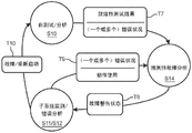
More particularly, referring to fig. 1, the illustrated operational readiness assessment state diagram includes a self-test/analysis state S10, a subsystem monitoring state S11, an error analysis state S12, and a service/repair state S13 for assessing the operational readiness of the emergency medical device.
Self-test/analysis state S10 contains the various self-tests performed by the emergency medical device on each subsystem of the emergency medical device. As will be explained further later herein, the subsystems of the emergency medical device employ operational components for running emergency medical procedures including, but not limited to, electrocardiogram monitoring procedures, defibrillation shock therapy procedures, synchronized cardioversion therapy procedures, and transcutaneous pacing therapy procedures. Self-testing of such operational components involves delineation of hard functional limitations between being considered either operational-ready or non-operational due to the associated emergency medical procedures.
If one or more of the subsystems fails the self-test (S) run by the emergency medical device, the emergency medical device is switched to transition T1 to a service/repair state S13, wherein the emergency medical device indicates that service/repair is required for the emergency medical device (e.g., the red X-marked icon is activated).
Otherwise, if the subsystem (S) pass a self-test run by the emergency medical device, the emergency medical device is switched to transition T2 to a subsystem monitoring state S11 in which the emergency medical device indicates that all subsystems are ready ("RFU") (e.g., a green hook mark icon is activated).
During the subsystem monitoring state S11, while awaiting use or actually being used, the emergency medical device will be switched to transition T3 to the error analysis state S12 upon the occurrence of an error by the subsystem that threatens the operational readiness of the emergency medical device. The error may be a recoverable error or an unrecoverable error (i.e., a failure).
If the emergency medical device is able to recover from the error, the emergency medical device is switched to transition T4 back to the subsystem monitoring state S11.
If the emergency medical device is unable to recover from the error but is still rebooted by the operator or automatically, the emergency medical device is switched to transition T5 to a self-test/analysis state S10.
If the emergency medical device has a subsystem failure (S) without a reboot, the emergency medical device is switched to transition T6 to a service/repair state S13.
In practice, the operational readiness assessment state diagram may be implemented in various modes, but nevertheless, the subject state diagram is unable to detect condition(s) indicative of a possible operational failure of a subsystem of the emergency medical device in the near future.
Disclosure of Invention
The present invention incorporates predictive failure analysis within the emergency medical device to detect condition(s) indicative of the likely operational failure of the operational component(s) of the emergency medical subsystem(s) in the near future.
One form of the present invention is an emergency medical device (e.g., an external defibrillator/monitor) that employs an emergency medical subsystem (e.g., a monitoring subsystem or a therapy subsystem) for running an emergency medical procedure, and an emergency medical controller for controlling activation of the emergency medical subsystem. The subsystem includes one or more operational components. In operation, the controller conditionally actuates a device readiness indicator (e.g., audible or visual) that indicates operational readiness of the operational component(s), and conditionally actuates a fault warning indicator (e.g., alert or visual) that indicates an impending fault of the operational component(s). The fault warning indicator may be actuated based on: predictive failure analysis of premature degradation of the operational component(s), repeated occurrence of error conditions, particularly recoverable error conditions, of the operational component(s), and shortened reliable life of the operational component(s).
For purposes of the present invention, terms of art, including, but not limited to, "emergency medical device," "emergency medical subsystem," "emergency medical procedure," "operational component," and "device readiness indicator," are to be construed as known in the art of the present invention and as exemplarily described herein.
For the purposes of the present invention, the "device readiness indicator" and the "fault warning indicator" may be separate indicators (e.g., the device readiness indicator is a dedicated visual indicator and the fault warning indicator is displayed on a user interface) or integrated indicators (e.g., the fault warning indicator is a flashing of a dedicated visual indicator).
For the purposes of the present invention, the term "controller" broadly encompasses all structural configurations of dedicated motherboards or application specific integrated circuits installed within or connected to emergency medical equipment for controlling the application of the various inventive principles of the present invention as described subsequently herein. The structural configuration of the controller may include, but is not limited to, processor(s), computer-usable/computer-readable storage medium(s), operating system, application module(s), peripheral device controller(s), slot(s), and port(s).
For purposes of this disclosure, the term "application module" broadly encompasses electronic circuitry or executable programs (e.g., executable software and/or firmware) for running a particular application.
A second form of the present invention is a method of operating the emergency medical device. The method includes the emergency medical controller conditionally generating a device readiness indicator indicative of an operational readiness of the operational component(s) running the emergency medical procedure, and the emergency medical controller conditionally generating a fault warning indicator indicative of a forthcoming fault of the operational readiness of the operational component(s) running the emergency medical procedure.
The foregoing forms as well as other forms of the present invention, and various features and advantages of the present invention, will become further apparent from the following detailed description of various embodiments of the present invention read in conjunction with the accompanying drawings. The detailed description and drawings are merely illustrative of the invention rather than limiting, the scope of the invention being defined by the claims and equivalents thereof.
Drawings
FIG. 1 illustrates an exemplary state diagram to demonstrate a method of operational readiness assessment of an emergency medical device as known in the art;
FIG. 2 illustrates an exemplary embodiment of an emergency medical device according to the present invention;
FIG. 3 illustrates an exemplary state diagram to demonstrate the inventive principles of a fault warning method of an emergency medical device according to the present invention;
FIG. 4 illustrates an exemplary bathtub curve to demonstrate the inventive principles of predictive failure analysis by emergency medical equipment in accordance with the present invention;
figure 5 illustrates an exemplary embodiment of a defibrillator controller according to the present invention; and is
Fig. 6 illustrates an exemplary embodiment of a preparation module according to the present invention.
Detailed Description
To facilitate an understanding of the present invention, exemplary embodiments of the present invention will be provided herein that relate to an implementation of predictive failure analysis by an emergency medical controller of the present invention.
Referring to FIG. 2, an emergency medical device 20 (e.g., an external defibrillator/monitor) employs X emergency medical subsystems 21 for running X emergency medical procedures, X ≧ 1. Examples of subsystems 21 include, but are not limited to:
(1) an electrocardiogram ("ECG") monitoring subsystem for generating and displaying an ECG of a patient connected to the device 20 via leads; and
(2) a therapy subsystem for applying defibrillation shocks, synchronized cardioversion, or transcutaneous pacing to a patient connected/coupled to device 20 via a lead/electrode pad/electrode handle (paddle). Each subsystem 21 employs Y operational components structurally assembled to run a corresponding emergency medical procedure, Y ≧ 1. Examples of operational components 22 include, but are not limited to, electronic, mechanical, and electromechanical components currently used in commercially available emergency medical devices (e.g., philips HeartStart MRx and XL + defibrillator/monitors).
The emergency medical device 20 also employs Z emergency medical controllers 23, Z ≧ 1, for controlling activation of the subsystem(s) 21 in the running emergency medical procedure(s). In practice, each controller 23 may employ an operating system module for overall device control and various application modules for self-test(s), predictive failure analysis and activation subsystem 21 as is known in the art. Examples of application modules include, but are not limited to:
(1) an operational readiness test module for running self-tests of subsystem(s) 21 and controller 23 as known in the art and previously described herein exemplarily (fig. 1);
(2) a predictive fault analysis module for detecting condition(s) indicative of a likely operational fault in the near future of the subsystem(s) and controller 23, as will be further exemplarily described herein (fig. 3);
(3) a monitoring module for controlling activation of a monitoring subsystem, as exemplarily described previously herein (fig. 2); and
(4) a therapy module for controlling activation of the therapy subsystem, as exemplarily described previously herein (fig. 2).
More specifically, for the operational readiness test module, the controller 23 actuates the device readiness indicator 24, which indicates any one of:
(1) operational readiness of the operational component(s) 22 of each subsystem 21 based on a passing result of the operational readiness test performed by the operational readiness test module; or
(2) Non-operational readiness of operational component(s) 22 of one or more subsystems 21 based on a failed result of the operational readiness test performed by the operational readiness test module. In practice, the device readiness indicator 24 may have a variety of configurations, including but not limited to:
(1) a form of visible light (e.g., a green hook sign for operational readiness, a red X for non-operational readiness, and a flashing light for immediate attention);
(2) icon and/or text visual forms (e.g., icons and/or text displayed on a monitor); and/or
(3) An audio form (e.g., a series of beeps for immediate attention or a voice recording stating operational or non-operational readiness).
More specifically, for the predictive fault analysis module, the controller 23 actuates the fault warning indicator 25 upon indication of a likely future operational fault of the subsystem(s) 21 and the controller 23 based on the detection by the condition module(s). Examples of such conditions include, but are not limited to:
(1) premature degradation of the operational component(s) 22 of the subsystem(s) 21;
(2) repeated occurrences of an error condition (particularly a recoverable error condition) at operational component(s) 22 of subsystem(s) 21; and
(3) shortened reliable life of the operational component(s) 22 of the subsystem(s) 21.
In practice, the fault warning indicator 25 may also have various configurations, including but not limited to:
(1) visible light forms (e.g., green hook sign for operational readiness, red X for non-operational readiness, and flashing lights for immediate attention);
(2) icon and/or text visual forms (e.g., icons and/or text displayed on a monitor); and/or
(3 audio form (e.g., for a series of beeps immediately focused or voice recordings stating operational or non-operational readiness).
For example, referring to FIG. 3, the fault warning state diagram includes a self-test/analysis state S10 (FIG. 1), a subsystem monitoring state S11 (FIG. 1), an error analysis state S12 (FIG. 1), and a novel and unique predictive fault analysis state S14.
As previously described herein, self-test/analysis state S10 includes the execution of various self-tests by the emergency medical device on each subsystem of the emergency medical device.
After the self-tests are fully performed, the controller 23 is switched to transition T7 to predictive failure analysis state S14 in which the test results are analyzed for any indication of premature degradation of the operational component (S) 22 and any error conditions are analyzed for repeated occurrences of a particular or related error condition.
Premature degradation.Automated self-tests are typically designed with hard fault limits to determine the pass/fail results of the test. However, not every failure mode easily falls into a good or bad partition, as there will be cases: the component will deteriorate over the life of the product and will slowly pass the pass/fail limit of the readiness test. The present invention recognizes that for some types of self-tests, soft fault limits may be used as predictors of future faults, where test results outside of hard fault limits will continue to result in failed test results, and where test results outside of soft fault limits but within hard fault limits will result in early fault alerts.
More particularly, referring to the "bathtub curve," as shown in FIG. 4, a typical lifecycle for many types of operational components 22 has three (3) distinct periods, including an early failure I, a normal life N, and an end of life E. To mitigate early failure period I, subsystem 21 may be "burned in" and/or operational component 22 screened during manufacturing. Thus, the device design goal is for the normal life N of each operational component 22 to extend further than the expected life of the overall device 20. However, there are many factors that may lead to premature failure of the operating member 22.
For example, a popular technique for defibrillator capacitors includes the use of metalized dry film polypropylene energy storage capacitors. These capacitors exhibit self-healing properties, in which small defects in the film are removed by clearing the affected foil areas. In high pulse applications (such as defibrillation), the mechanical and thermal stresses normally used will occasionally create new failure sites, which will also be cleared. This results in a very small gradual decrease in the capacitor value. By design, these reductions are too small to be expected to remain within the rated tolerances during the life of the product. However, it is possible that some capacitors subject to extreme use conditions or extreme environmental conditions may exhibit a capacitance loss sufficient to exceed the hard failure limit ("HFL") of the device self-test.
Still referring to fig. 4, exceeding the hard fault limit ("HFL") will create an indication that the device 20 is not ready. Conversely, as exemplarily illustrated, a soft fault limit ("SFL") that is set greater than a hard fault limit ("HFL") and less than a nominal expected variance ("NVE") with respect to the life expectancy of the operational component 22 provides an indication that the equipment 20 is still ready, but should be serviced soon if the operational component(s) 22 are outside the soft fault limit.
Error condition(s).During device self-test, an error condition may be detected that is not severe enough to be considered a device failure. Examples of such errors are intermittent and recoverable error conditions. In particular, intermittent errors may be caused by electromagnetic interference from random noise, cosmic rays, or other nearby electronic devices. Recoverable errors may include software error conditions that may be cleared by a restart, or data transmission errors where retransmission is possible.
When device 20 recovers from an error condition, controller 23 will continue to show device 20 via indicator 24 as ready. However, if many instances of a particular recoverable error condition are observed during a short period of time, the root cause of the error is an increased likelihood of a real device failure or a delayed design defect. Furthermore, device performance may be affected if the rate of occurrence of recoverable error conditions increases.
Thus, repeated occurrences of a particular error condition or related error conditions are analyzed for any indication of an impending device failure.
Referring back to fig. 3, if apparatus 20 is ready, upon determining any repeated occurrence of the fault warning state and error condition (S) derived from the analysis of the premature degradation of operational component (S) 22, controller 23 is switched to transition T8 to monitor/analyze state S11/S12. The fault warning state is either the generation of the fault warning indicator 25 or the non-generation of the fault warning indicator 25.
During normal operation of apparatus 20, controller 23 is periodically switched to transition T9 back to predictive failure analysis state S14 for analyzing the error condition (S) and new or additional occurrence (S) of usage pattern of particular individual component (S) 22.
Error condition(s).During normal operation of device 20, error conditions (particularly recoverable error conditions) may be detected that are not severe enough to be considered a device failure. Furthermore, repeated occurrences of particular error conditions or related error conditions are therefore analyzed for any indication of impending device failure.
The components are used.Most electrical, mechanical and electromechanical components 22 are subject to wear that can shorten their useful life. For example, the connector is designed to resist a limited number of connect/disconnect cycles, whereby each connect/disconnect may cause a small amount of frictional wear on the contact surfaces, eventually wearing away the gold plating required for good electrical contact. The connector to be used is rated for the desired use. However, in extreme use conditions, it may fail.
The usage patterns of some or all of operational component(s) 22 are analyzed to determine whether the usable life of such component(s) has been shortened.
Referring back to FIG. 3, upon determining a fault warning state derived from analysis of the error condition (S) and any reoccurrence of the component usage pattern, the controller 23 is again switched to transition T8 to monitor/analyze state S11/S12. Further, the fault warning state is either the generation of the fault warning indicator 25 or the non-generation of the fault warning indicator 25.
Also, during normal operation of device 20, controller 23 may be switched to transition T10 back to self-test/analysis state S10 upon rebooting device 20 to overcome non-removable errors or malfunctions of device 20. As previously described herein, if the apparatus 20 is ready, the test results are again analyzed for any indication of premature degradation of the operational component(s) 22, and any test error condition is again analyzed for any particular error condition or repeated occurrence of a related error condition.
Referring back to fig. 2, in practice, the fault warning state diagram of fig. 3 may be implemented in various modes by the controller 23, but regardless the subject state diagram detects condition(s) indicative of a likely future operational failure of the subsystem 21 of the emergency medical device 20.
To facilitate a further understanding of the predictive failure analysis of the present invention, fig. 5 illustrates an exemplary defibrillator controller 30 employing a monitoring module 31 for controlling activation of the ECG module subsystem and a therapy module 32 for controlling activation of the defibrillation therapy subsystem.
Defibrillation controller 30 also employs a self-evaluation module 33 for running self-test and predictive fault analysis of the subsystems. In practice, the self-evaluation module 33 may include sub-modules for separately running the self-test and predictive fault analysis of the subsystem, or may be a single module for integrally running the self-test and predictive fault analysis of the subsystem. FIG. 6 illustrates an embodiment 40 of self-evaluation module 33 that integrally runs self-test and predictive failure analysis of a subsystem.
Referring to fig. 6, self-evaluation module 40 employs a self-tester 41, a runtime monitor 42, a device readiness analyzer 43, and a predictive failure analyzer 44. The module 40 will be described based on the data flow between the components 41-44.
Self-tester 41 runs known self-tests to ensure that all subsystems will run correctly. These self-tests are automatically initiated periodically when the device has power but is turned off (e.g., not in clinical use). Self-test generation includes retrieving, either directly or via storage, the pass/fail result of any occurrence of recoverable error condition(s) passed to analyzer 43 and analyzer 44.
The runtime monitor 42 monitors the device for any occurrence of an error condition (particularly a fault) when the device is turned on (e.g., in clinical use). Based on the detection of the error condition, the runtime error condition 42 will initiate the necessary steps to attempt recovery of the error condition and record the condition(s) and recovery effort(s). The error condition is passed to the device readiness analyzer 43, either directly or via storage retrieval, and the error log is passed to the predictive failure analyzer 44, either directly or via storage retrieval.
The runtime monitor 42 also generates usage logs that inform various components of usage patterns, including but not limited to:
(1) a count of a number of charging cycles of a therapy capacitor of the defibrillator;
(2) a count of the number of charge/discharge cycles on a battery of the defibrillator;
(3) counting the number of on/off cycles of the switch;
(4) counting the number of on/off cycles of the relay;
(5) a count of a number of connection/disconnection cycles of the exterior connector port;
(6) a record of the exposure of extreme temperatures that can cause solder bonding stresses to be excessive or semiconductor mold and package cracking (e.g., using an internal thermistor);
(7) a record of exposure to extreme humidity that can cause corrosion or cracking (e.g., using an internal hygrometer); and
(8) the recording exposure to extreme shock and vibration conditions that can accelerate the degradation of components such as electrical contacts of a connector.
The run-time monitor 42 communicates the usage log to the predictive failure analyzer 45, either directly or via stored retrieval.
The device readiness analyzer 43 analyzes the test results against hard fault limits and analyzes errors to determine whether the device is ready or has a fault requiring immediate service as is known in the art, and applies a readiness signal to a device readiness indicator 50 (e.g., a light, a speaker, etc.) to indicate upon actuation/activation of the indicator 50 that the device is operationally ready or inoperable for clinical use and requires immediate service.
In response to the test results, predictive failure analyzer 44 determines whether any of the components will show premature degradation. To this end, the analyzer 44 applies soft functional limits to components, including but not limited to:
(1) testing the voltage level of the power subsystem;
(2) timing of components having optical detectors subject to clogging wear;
(3) the capacitance of the therapy capacitor(s) of the defibrillator; and
(4) the charge capacity of the battery of the defibrillator.
In response to the test errors and error logs, predictive failure analyzer 44 determines whether repeated occurrences of a particular error condition or related error conditions indicate (warrange) an alert of an upcoming subsystem failure.
More particularly, a single occurrence of a recovered error condition (where a threshold of multiple sequential occurrences of such error condition would render the device unusable for warning indicative of an upcoming subsystem failure).
Further, a single occurrence of an unrecoverable error (fault) condition cleared by a successful self-test may indicate an alert of an impending subsystem fault. For example, when each fault occurs, the analyzer 43 will determine that the device is not ready. However, the defibrillator user may initiate the self-tester 41 and the fault may no longer occur, which causes the analyzer 43 to change the indicator 50 to readiness. If such intermittent fault conditions reoccur too frequently, as measured against a threshold, it indicates an increased likelihood of an impending hard fault and indicates a warning of an impending subsystem fault.
In response to the usage log, the analyzer 44 will measure the usage pattern against a threshold value representing an unacceptable reduction in the reliable useful life of the operating components.
According to various predictive fault tests, upon detection of a possible fault in the near future operational readiness of the defibrillator's operational components/subsystems, the analyzer 45 will generate a fault warning signal to energize or actuate a fault warning indicator 51 (e.g., a light, speaker, etc.).
Referring to fig. 2-6, those having ordinary skill in the art will appreciate the many benefits of the present invention including, but not limited to:
(1) the likelihood of a defibrillator or other emergency use medical device failing when it is needed for clinical use is reduced. In particular, if the device detects a condition indicating that an internal component or subsystem may fail in the near future, the user device is warned in advance. The alert allows the device user to repair or replace the device before it is needed for an emergency.
(2) Reduction of equipment maintenance and service costs. In particular, with current readiness techniques, in many cases, the equipment will be returned to the factory due to the failure indication, but the problem cannot be reproduced. The most likely component (i.e., the circuit board) will be replaced and the device returned to the user. This process may be repeated multiple times before other components (e.g., the therapy capacitor) will be eventually replaced to resolve the problem. By the predictive failure analysis of the present invention, the number of false failures is reduced because failure trends are indicated differently than hard failures. Additionally, predictive failure analysis provides specific diagnostic information (e.g., trend data for near failure of a component); and
(3) reduction in cost of ownership of the device. In particular, some device components may have a shorter expected life than the device itself. Examples are batteries and accessories (such as patient vital signs sensors and cables). For current practice, the user is instructed by the manufacturer to replace the parts according to a schedule established by reliability life analysis and testing. In other words, the battery may need to be replaced every three years based on the desired device usage scenario. Through the predictive failure analysis of the present invention, device usage is recorded, wherein batteries in lightly used devices may be replaced less frequently.
Furthermore, as will be appreciated by those of ordinary skill in the art in view of the teachings provided herein, the features, elements, components, etc. described in this disclosure/specification and/or depicted in fig. 2-6 may be implemented in various combinations of electronic components/circuitry, hardware, executable software and executable firmware (particularly as application modules of a controller, as described herein) and provide functionality that may be combined in a single element or multiple elements. For example, the functions of the various features, elements, components, etc. shown/illustrated/depicted in fig. 2-6 may be provided through the use of dedicated hardware as well as hardware capable of executing software in association with appropriate software. When provided by a processor, the functions may be provided by a single dedicated processor, by a single shared processor, or by a plurality of individual processors, some of which may be shared and/or multiplexed. Moreover, explicit use of the term "processor" should not be construed to refer exclusively to hardware capable of executing software, and can implicitly include, without limitation, digital signal processor ("DSP") hardware, memory (e.g., read only memory ("ROM") for storing software, random access memory ("RAM"), non-volatile storage, etc.), and any virtual module and/or machine (including hardware, software, firmware, circuitry, combinations thereof, etc.) that is capable of (and/or configurable) to perform and/or control a process.
Moreover, all statements herein reciting principles, aspects, and embodiments of the invention, as well as specific examples thereof, are intended to encompass both structural and functional equivalents thereof. Additionally, it is intended that such equivalents include both currently known equivalents as well as equivalents developed in the future (e.g., any elements developed that perform the same or substantially similar function, regardless of structure). Thus, for example, any block diagrams presented herein may represent conceptual views of illustrative system components and/or circuitry embodying the principles of the invention, as will be appreciated by those skilled in the art in view of the teachings provided herein. Similarly, those of ordinary skill in the art will appreciate in view of the teachings provided herein that any flow charts, flow diagrams, and the like may represent various processes which may be substantially represented in computer readable storage medium and so executed by a computer, processor, or other device having processing capability, whether or not such computer or processor is explicitly shown.
Furthermore, exemplary embodiments of the invention can take the form of a computer program product or an application module accessible from a computer-usable and/or computer-readable storage medium providing program code and/or instructions for use by or in connection with a computer or any instruction execution system. In accordance with the present disclosure, a computer-usable or computer-readable storage medium may be any apparatus that can contain, store, communicate, propagate, or transport the program for use by or in connection with the instruction execution system, apparatus, or device. Such an exemplary medium may be, for example, an electronic, magnetic, optical, electromagnetic, infrared, or semiconductor system (or apparatus or device) or a propagation medium. Examples of a computer-readable medium include, for example, a semiconductor or solid state memory, magnetic tape, a removable computer diskette, a Random Access Memory (RAM), a read-only memory (ROM), a flash memory (drive), a rigid magnetic disk and an optical disk. Current examples of optical disks include compact disk-read only memory (CD-ROM), compact disk-read/write (CD-R/W), and DVD. Moreover, it should be appreciated that any new computer-readable media that may be developed thereafter is also to be considered computer-readable media, as may be used or referenced in accordance with the present invention and the exemplary embodiments of the present disclosure.
Having described preferred and exemplary embodiments of a novel and inventive advanced warning indicator for emergency medical equipment (which are intended to be illustrative and not limiting), it is noted that modifications and variations can be made by persons skilled in the art in light of the teachings provided herein, including in fig. 2-6. It is therefore to be understood that changes may be made in the preferred and exemplary embodiments or variations thereof within the scope of the embodiments disclosed herein.
Moreover, it is contemplated that the inclusion and/or implementation of devices or corresponding and/or related information such as may be used/implemented in devices according to the present disclosure is also contemplated and considered to be within the scope of the present invention. Moreover, corresponding and/or related methods of making and/or using devices and/or systems according to the present disclosure are also contemplated and considered to be within the scope of the present invention.
Claims (15)
1. An emergency medical device (20), comprising:
an emergency medical subsystem (21) including at least one operational component (22) that degrades over the life of the emergency medical device, the subsystem being capable of running an emergency medical procedure; and
an emergency medical controller (23) capable of controlling activation of the emergency medical subsystem (21),
wherein the emergency medical controller (23) is structurally configured to conditionally actuate an equipment readiness indicator (24) indicating an operational readiness of the at least one operational component (22) to run the emergency medical procedure,
wherein the emergency medical controller (23) is structurally configured to conditionally actuate a fault warning indicator (25) indicating a forthcoming fault of the operational readiness of the at least one operational component (22) to run the emergency medical procedure, indicated by the equipment readiness indicator (24), and
wherein the emergency medical controller (23) comprises a predictive failure analyzer (44) structurally configured to actuate the failure warning indicator based on predictive failure analysis of premature degradation of the at least one operational component (22).
2. The emergency medical device (20) of claim 1,
wherein the emergency medical controller (23) is structurally configured to conduct an operational readiness test of the at least one operational component (22);
wherein the emergency medical controller (23) actuates the device readiness indicator (24) in response to a pass result of the operational readiness test; and is
Wherein the emergency medical controller (23) actuates the fault warning indicator (25) in response to a pass result of the operational readiness test indicating premature degradation of the at least one operational component (22).
3. The emergency medical device (20) of claim 1,
wherein the emergency medical controller (23) is structurally configured to record repeated occurrences of an error condition of the at least one operational component (22); and is
Wherein the emergency medical controller (23) actuates the fault warning indicator (25) in response to a warning frequency of the repeated occurrence of the error condition of the at least one component (22).
4. The emergency medical device (20) of claim 3,
wherein the error condition is recoverable by the emergency medical controller (23).
5. The emergency medical device (20) of claim 3,
wherein the error condition is not recoverable by the emergency medical controller (23).
6. The emergency medical device (20) of claim 1,
wherein the emergency medical controller (23) is structurally configured to monitor a usage pattern of the at least one operational component (22); and is
Wherein the emergency medical controller (23) actuates the fault warning indicator (25) in response to the usage pattern indicating a shortened reliable life of the at least one operational component (22).
7. The emergency medical device (20) of claim 1, wherein the device readiness indicator (24) and the fault warning indicator (25) are integrated indicators.
8. The emergency medical device (20) of claim 1, wherein the device readiness indicator (24) and the fault warning indicator (25) are separate indicators.
9. The emergency medical device (20) of claim 1, wherein the predictive failure analyzer is further structurally configured to actuate the failure warning indicator based on at least one of: repeated occurrence of an error condition of the at least one operating member (22) and a shortened reliable life of the at least one operating member (22).
10. A method of operating an emergency medical device (20) including at least one operational component (22) that degrades over a lifetime of the emergency medical device, the method comprising:
an emergency medical controller (23) conditionally generates a device readiness indicator (24) indicating an operational readiness of the at least one operational component (22) to run an emergency medical procedure;
the emergency medical controller (23) conditionally generates a fault warning indicator (25) indicating a forthcoming fault in the operational readiness of the at least one operational component (22) indicated by the device readiness indicator (24), and
wherein the emergency medical controller (23) comprises a predictive failure analyzer (44) structurally configured to actuate the failure warning indicator based on predictive failure analysis of premature degradation of the at least one operational component (22).
11. The method of claim 10, wherein the first and second light sources are selected from the group consisting of,
wherein the emergency medical device (20) conducts an operational readiness test of the at least one operational component (22);
wherein the emergency medical device (20) actuates the device readiness indicator (24) in response to a result of the passing of the operational readiness test; and is
Wherein the emergency medical device (20) actuates the fault warning indicator (25) in response to a pass result of the operational readiness test indicating premature degradation of the at least one operational component (22).
12. The method of claim 10, wherein the first and second light sources are selected from the group consisting of,
wherein the emergency medical device (20) records a recurring occurrence of an error condition of the at least one operational component (22); and is
Wherein the emergency medical device (20) actuates the fault warning indicator (25) in response to a warning frequency of the repeated occurrence of the error condition of the at least one component (22).
13. The method of claim 12, wherein the first and second light sources are selected from the group consisting of,
wherein the error condition is recoverable by the emergency medical controller (23).
14. The method of claim 12, wherein the first and second light sources are selected from the group consisting of,
wherein the error condition is not recoverable by the emergency medical controller (23).
15. The method of claim 10, wherein the first and second light sources are selected from the group consisting of,
wherein, in response to generation of the device readiness indicator (24), the emergency medical device (20) monitors a usage pattern of the at least one operational component (22); and is
Wherein the emergency medical device (20) actuates the fault warning indicator (25) in response to the usage pattern indicating a shortened reliable life of the at least one operational component (22).
Applications Claiming Priority (3)
| Application Number | Priority Date | Filing Date | Title |
|---|---|---|---|
| US201462097763P | 2014-12-30 | 2014-12-30 | |
| US62/097,763 | 2014-12-30 | ||
| PCT/IB2015/059983 WO2016108163A1 (en) | 2014-12-30 | 2015-12-24 | Advanced warning indicator for emergency medcial devices |
Publications (2)
| Publication Number | Publication Date |
|---|---|
| CN107111680A CN107111680A (en) | 2017-08-29 |
| CN107111680B true CN107111680B (en) | 2020-11-03 |
Family
ID=55174683
Family Applications (1)
| Application Number | Title | Priority Date | Filing Date |
|---|---|---|---|
| CN201580071919.2A Active CN107111680B (en) | 2014-12-30 | 2015-12-24 | Advanced warning indicator for emergency medical equipment |
Country Status (6)
| Country | Link |
|---|---|
| US (1) | US10201714B2 (en) |
| EP (1) | EP3240608B1 (en) |
| JP (1) | JP6574483B2 (en) |
| CN (1) | CN107111680B (en) |
| MX (1) | MX2017008602A (en) |
| WO (1) | WO2016108163A1 (en) |
Families Citing this family (14)
| Publication number | Priority date | Publication date | Assignee | Title |
|---|---|---|---|---|
| EP3067671A1 (en) * | 2015-03-13 | 2016-09-14 | Flowgem Limited | Flow determination |
| WO2017062042A1 (en) | 2015-10-07 | 2017-04-13 | Smith & Nephew, Inc. | Systems and methods for applying reduced pressure therapy |
| CA3023932A1 (en) | 2016-05-13 | 2017-11-16 | Smith & Nephew, Inc. | Automatic wound coupling detection in negative pressure wound therapy systems |
| AU2017335635B2 (en) | 2016-09-29 | 2023-01-05 | Smith & Nephew, Inc. | Construction and protection of components in negative pressure wound therapy systems |
| CN110545766A (en) | 2017-03-07 | 2019-12-06 | 史密夫和内修有限公司 | Reduced pressure treatment systems and methods including antennas |
| WO2019014141A1 (en) | 2017-07-10 | 2019-01-17 | Smith & Nephew, Inc. | Systems and methods for directly interacting with communications module of wound therapy apparatus |
| WO2019032510A1 (en) | 2017-08-07 | 2019-02-14 | Rescue Box, Inc. | Smart safety kits |
| US11497663B2 (en) | 2017-08-07 | 2022-11-15 | Rescue Box, Inc. | Smart safety kits |
| US10527516B2 (en) * | 2017-11-20 | 2020-01-07 | Phyn Llc | Passive leak detection for building water supply |
| EP3637429A1 (en) * | 2018-10-10 | 2020-04-15 | Gambro Lundia AB | Operating a medical device during startup and shutdown |
| GB201820668D0 (en) | 2018-12-19 | 2019-01-30 | Smith & Nephew Inc | Systems and methods for delivering prescribed wound therapy |
| US10806939B1 (en) | 2019-05-24 | 2020-10-20 | Galibots Inc. | Independent readiness determination for automated external defibrillator deployment |
| JP7343556B2 (en) * | 2021-08-20 | 2023-09-12 | ウェスト・アファム・ホールディングス・ディーエーシー | positive system alert |
| CN116805530A (en) * | 2023-08-23 | 2023-09-26 | 领华数科(厦门)信息技术有限公司 | Medical equipment use efficiency assessment method based on artificial intelligence |
Citations (2)
| Publication number | Priority date | Publication date | Assignee | Title |
|---|---|---|---|---|
| WO2014033605A1 (en) * | 2012-08-29 | 2014-03-06 | Koninklijke Philips N.V. | Environment and use monitoring system for advanced life support devices |
| WO2014097035A1 (en) * | 2012-12-17 | 2014-06-26 | Koninklijke Philips N.V. | Adaptive self-testing and stress analysis of medical devices |
Family Cites Families (20)
| Publication number | Priority date | Publication date | Assignee | Title |
|---|---|---|---|---|
| DE3020620C2 (en) * | 1980-05-30 | 1984-08-02 | Hellige Gmbh, 7800 Freiburg | Device for measuring and displaying the consumed portion of the theoretically expected total service life of a capacitor |
| JPH10314318A (en) * | 1997-05-21 | 1998-12-02 | Kaajiopeeshingu Res Lab:Kk | Heart pacemaker device |
| US5899925A (en) * | 1997-08-07 | 1999-05-04 | Heartstream, Inc. | Method and apparatus for aperiodic self-testing of a defibrillator |
| JP4020556B2 (en) * | 2000-01-21 | 2007-12-12 | オリンパス株式会社 | Ultrasonic drive circuit and ultrasonic surgical device |
| GB2380677B (en) * | 2001-09-07 | 2006-02-01 | Desmond Bryan Mills | Contact electrode |
| US7930023B2 (en) | 2001-09-21 | 2011-04-19 | Defibtech, Llc | Automatic external defibrillator with active status indicator |
| EP1521615A4 (en) * | 2002-06-11 | 2010-11-03 | Jeffrey A Matos | System for cardiac resuscitation |
| US20040143297A1 (en) * | 2003-01-21 | 2004-07-22 | Maynard Ramsey | Advanced automatic external defibrillator powered by alternative and optionally multiple electrical power sources and a new business method for single use AED distribution and refurbishment |
| US7570994B2 (en) * | 2003-04-25 | 2009-08-04 | Medtronic Physio-Control Corp. | Apparatus and method for maintaining a defibrillator battery charge and optionally communicating |
| US7706878B2 (en) * | 2004-05-07 | 2010-04-27 | Zoll Medical Corporation | Automated caregiving device with prompting based on caregiver progress |
| US7510526B2 (en) * | 2004-12-30 | 2009-03-31 | Medtronic Emergency Response Systems, Inc. | Medical device information system |
| JP2006218238A (en) * | 2005-02-14 | 2006-08-24 | Olympus Corp | Surgical operation system |
| US8271082B2 (en) * | 2007-06-07 | 2012-09-18 | Zoll Medical Corporation | Medical device configured to test for user responsiveness |
| US8165849B2 (en) | 2008-07-14 | 2012-04-24 | General Electric Company | Medical equipment monitoring method and system |
| US8344899B2 (en) * | 2010-10-04 | 2013-01-01 | Physio-Control, Inc. | Power conserving alert for medical devices |
| US8985326B2 (en) * | 2010-11-11 | 2015-03-24 | Koninklijke Philips N.V. | Carrying case for defibrillator with integrated button tester |
| US9289621B2 (en) * | 2012-05-08 | 2016-03-22 | Physio-Control, Inc. | Defibrillator network system |
| US9375584B2 (en) * | 2012-05-22 | 2016-06-28 | Physio-Control, Inc. | Medical device with lack-of-readiness alarm |
| MX358817B (en) * | 2012-12-26 | 2018-09-05 | Koninklijke Philips Nv | Intuitive overlaid readiness indicator for defibrillators. |
| EP3122423B1 (en) | 2014-03-27 | 2021-06-16 | Koninklijke Philips N.V. | Encoded status indicator for automated external defibrillators |
-
2015
- 2015-12-24 EP EP15825967.1A patent/EP3240608B1/en active Active
- 2015-12-24 MX MX2017008602A patent/MX2017008602A/en unknown
- 2015-12-24 WO PCT/IB2015/059983 patent/WO2016108163A1/en active Application Filing
- 2015-12-24 CN CN201580071919.2A patent/CN107111680B/en active Active
- 2015-12-24 US US15/540,119 patent/US10201714B2/en active Active
- 2015-12-24 JP JP2017534686A patent/JP6574483B2/en active Active
Patent Citations (2)
| Publication number | Priority date | Publication date | Assignee | Title |
|---|---|---|---|---|
| WO2014033605A1 (en) * | 2012-08-29 | 2014-03-06 | Koninklijke Philips N.V. | Environment and use monitoring system for advanced life support devices |
| WO2014097035A1 (en) * | 2012-12-17 | 2014-06-26 | Koninklijke Philips N.V. | Adaptive self-testing and stress analysis of medical devices |
Also Published As
| Publication number | Publication date |
|---|---|
| EP3240608A1 (en) | 2017-11-08 |
| MX2017008602A (en) | 2017-11-15 |
| JP6574483B2 (en) | 2019-09-11 |
| JP2018508240A (en) | 2018-03-29 |
| EP3240608B1 (en) | 2019-11-20 |
| WO2016108163A1 (en) | 2016-07-07 |
| US10201714B2 (en) | 2019-02-12 |
| US20180001097A1 (en) | 2018-01-04 |
| CN107111680A (en) | 2017-08-29 |
Similar Documents
| Publication | Publication Date | Title |
|---|---|---|
| CN107111680B (en) | Advanced warning indicator for emergency medical equipment | |
| CN109783262B (en) | Fault data processing method, device, server and computer readable storage medium | |
| CN107145410B (en) | Method, system and equipment for automatically powering on and starting up system after abnormal power failure | |
| JP5476238B2 (en) | Semiconductor device | |
| US8065004B2 (en) | Method and apparatus for automatic self-test of medical device | |
| US7844844B2 (en) | System and method for reserving information handling system battery charge to perform diagnostics | |
| CN103487673A (en) | Apparatus and method for automated testing of device under test | |
| US20140059390A1 (en) | Use of service processor to retrieve hardware information | |
| US20080123278A1 (en) | Slot availability indication system and method for indicating slot availability | |
| CN105955864B (en) | Power failure processing method, power module, monitoring management module and server | |
| CN115454703A (en) | Slow disk isolation control method and device, equipment and storage medium | |
| JP7057168B2 (en) | Failure detection device and failure analysis method | |
| KR101366416B1 (en) | Charging system with diagnostic function for battery life | |
| US8661288B2 (en) | Diagnosis system for removable media drive | |
| CN106130815B (en) | Board level testing method and device | |
| US20230375602A1 (en) | Detecting electrical power line disturbances | |
| CN112256535A (en) | Hard disk alarm method and device, computer equipment and storage medium | |
| CN110928213A (en) | Exception handling method, device and equipment and exception handler | |
| US20140351620A1 (en) | Power supply detecting system and detecting method | |
| JP6317172B2 (en) | Medical equipment | |
| JP2019068540A (en) | Battery replacement information detection device and method | |
| CN114515387A (en) | Defibrillator, self-test method of defibrillator and computer readable storage medium | |
| CN118012687A (en) | Test method, test device, electronic equipment and storage medium | |
| CN117687863A (en) | Computer equipment monitoring device and method | |
| JP2002168887A (en) | Evaluation device for abnormality in blackout |
Legal Events
| Date | Code | Title | Description |
|---|---|---|---|
| PB01 | Publication | ||
| PB01 | Publication | ||
| SE01 | Entry into force of request for substantive examination | ||
| SE01 | Entry into force of request for substantive examination | ||
| GR01 | Patent grant | ||
| GR01 | Patent grant |