CN107087402B - Laminated vehicle windshield with internally illuminated emblem - Google Patents
Laminated vehicle windshield with internally illuminated emblem Download PDFInfo
- Publication number
- CN107087402B CN107087402B CN201680003437.8A CN201680003437A CN107087402B CN 107087402 B CN107087402 B CN 107087402B CN 201680003437 A CN201680003437 A CN 201680003437A CN 107087402 B CN107087402 B CN 107087402B
- Authority
- CN
- China
- Prior art keywords
- curved
- oled device
- face
- recited
- vehicle windshield
- Prior art date
- Legal status (The legal status is an assumption and is not a legal conclusion. Google has not performed a legal analysis and makes no representation as to the accuracy of the status listed.)
- Expired - Fee Related
Links
- 239000011229 interlayer Substances 0.000 claims abstract description 19
- 239000010410 layer Substances 0.000 claims description 152
- 230000001681 protective effect Effects 0.000 claims description 67
- 230000000873 masking effect Effects 0.000 claims description 62
- 239000004020 conductor Substances 0.000 claims description 42
- 239000011521 glass Substances 0.000 claims description 38
- 239000000758 substrate Substances 0.000 claims description 33
- 239000000463 material Substances 0.000 claims description 23
- 239000000853 adhesive Substances 0.000 claims description 18
- 230000001070 adhesive effect Effects 0.000 claims description 18
- 239000003292 glue Substances 0.000 claims description 14
- 230000002093 peripheral effect Effects 0.000 claims description 10
- 229920005989 resin Polymers 0.000 claims description 10
- 239000011347 resin Substances 0.000 claims description 10
- 239000002966 varnish Substances 0.000 claims description 6
- 238000001429 visible spectrum Methods 0.000 claims description 5
- 230000004438 eyesight Effects 0.000 claims description 4
- 238000004891 communication Methods 0.000 claims description 2
- 239000012528 membrane Substances 0.000 claims description 2
- 239000003989 dielectric material Substances 0.000 claims 1
- 239000010408 film Substances 0.000 description 52
- 230000036961 partial effect Effects 0.000 description 14
- 239000005020 polyethylene terephthalate Substances 0.000 description 12
- 229920000139 polyethylene terephthalate Polymers 0.000 description 12
- 229910052751 metal Inorganic materials 0.000 description 11
- 239000002184 metal Substances 0.000 description 11
- 229920003023 plastic Polymers 0.000 description 11
- 239000004033 plastic Substances 0.000 description 11
- BQCADISMDOOEFD-UHFFFAOYSA-N Silver Chemical compound [Ag] BQCADISMDOOEFD-UHFFFAOYSA-N 0.000 description 9
- 229910052709 silver Inorganic materials 0.000 description 9
- 239000004332 silver Substances 0.000 description 9
- 239000002585 base Substances 0.000 description 8
- 229920002037 poly(vinyl butyral) polymer Polymers 0.000 description 8
- 230000000007 visual effect Effects 0.000 description 8
- 230000005540 biological transmission Effects 0.000 description 7
- 238000009826 distribution Methods 0.000 description 7
- 239000000499 gel Substances 0.000 description 7
- 239000000976 ink Substances 0.000 description 7
- 229910052500 inorganic mineral Inorganic materials 0.000 description 7
- 239000011707 mineral Substances 0.000 description 7
- 239000004417 polycarbonate Substances 0.000 description 7
- 239000004696 Poly ether ether ketone Substances 0.000 description 6
- 239000011248 coating agent Substances 0.000 description 6
- 238000000576 coating method Methods 0.000 description 6
- 210000003298 dental enamel Anatomy 0.000 description 6
- 230000000694 effects Effects 0.000 description 6
- 229920000515 polycarbonate Polymers 0.000 description 6
- 229920002530 polyetherether ketone Polymers 0.000 description 6
- 230000005855 radiation Effects 0.000 description 6
- 230000004888 barrier function Effects 0.000 description 5
- 238000007641 inkjet printing Methods 0.000 description 5
- 239000003550 marker Substances 0.000 description 5
- 239000002245 particle Substances 0.000 description 5
- 229920000642 polymer Polymers 0.000 description 5
- NIXOWILDQLNWCW-UHFFFAOYSA-M Acrylate Chemical compound [O-]C(=O)C=C NIXOWILDQLNWCW-UHFFFAOYSA-M 0.000 description 4
- 239000004642 Polyimide Substances 0.000 description 4
- 239000011230 binding agent Substances 0.000 description 4
- 239000003086 colorant Substances 0.000 description 4
- 238000000151 deposition Methods 0.000 description 4
- 238000010438 heat treatment Methods 0.000 description 4
- 239000002346 layers by function Substances 0.000 description 4
- 238000000034 method Methods 0.000 description 4
- 239000000203 mixture Substances 0.000 description 4
- 239000011112 polyethylene naphthalate Substances 0.000 description 4
- 229920001721 polyimide Polymers 0.000 description 4
- 239000004800 polyvinyl chloride Substances 0.000 description 4
- 238000007650 screen-printing Methods 0.000 description 4
- 239000010409 thin film Substances 0.000 description 4
- 238000010521 absorption reaction Methods 0.000 description 3
- 239000002390 adhesive tape Substances 0.000 description 3
- 230000008021 deposition Effects 0.000 description 3
- 238000003745 diagnosis Methods 0.000 description 3
- 230000003287 optical effect Effects 0.000 description 3
- 229920000728 polyester Polymers 0.000 description 3
- -1 polyethylene terephthalate Polymers 0.000 description 3
- 229920000915 polyvinyl chloride Polymers 0.000 description 3
- 230000002265 prevention Effects 0.000 description 3
- 238000005496 tempering Methods 0.000 description 3
- 229920000089 Cyclic olefin copolymer Polymers 0.000 description 2
- 239000004713 Cyclic olefin copolymer Substances 0.000 description 2
- 229910052783 alkali metal Inorganic materials 0.000 description 2
- 150000001340 alkali metals Chemical class 0.000 description 2
- 229910052782 aluminium Inorganic materials 0.000 description 2
- XAGFODPZIPBFFR-UHFFFAOYSA-N aluminium Chemical compound [Al] XAGFODPZIPBFFR-UHFFFAOYSA-N 0.000 description 2
- 238000005229 chemical vapour deposition Methods 0.000 description 2
- 230000001276 controlling effect Effects 0.000 description 2
- 238000013016 damping Methods 0.000 description 2
- 230000007423 decrease Effects 0.000 description 2
- 230000003247 decreasing effect Effects 0.000 description 2
- 239000000975 dye Substances 0.000 description 2
- 238000000295 emission spectrum Methods 0.000 description 2
- 238000005516 engineering process Methods 0.000 description 2
- 238000000605 extraction Methods 0.000 description 2
- 230000004313 glare Effects 0.000 description 2
- 239000004922 lacquer Substances 0.000 description 2
- 238000004519 manufacturing process Methods 0.000 description 2
- 239000011159 matrix material Substances 0.000 description 2
- 230000007935 neutral effect Effects 0.000 description 2
- 239000003973 paint Substances 0.000 description 2
- 238000005240 physical vapour deposition Methods 0.000 description 2
- 239000000049 pigment Substances 0.000 description 2
- 239000002985 plastic film Substances 0.000 description 2
- 229920006255 plastic film Polymers 0.000 description 2
- 229920001200 poly(ethylene-vinyl acetate) Polymers 0.000 description 2
- 239000011241 protective layer Substances 0.000 description 2
- 230000001105 regulatory effect Effects 0.000 description 2
- 229920002050 silicone resin Polymers 0.000 description 2
- 239000005361 soda-lime glass Substances 0.000 description 2
- 239000000126 substance Substances 0.000 description 2
- 229920001169 thermoplastic Polymers 0.000 description 2
- 239000004416 thermosoftening plastic Substances 0.000 description 2
- XOLBLPGZBRYERU-UHFFFAOYSA-N tin dioxide Chemical compound O=[Sn]=O XOLBLPGZBRYERU-UHFFFAOYSA-N 0.000 description 2
- 229910001887 tin oxide Inorganic materials 0.000 description 2
- YMHOBZXQZVXHBM-UHFFFAOYSA-N 2,5-dimethoxy-4-bromophenethylamine Chemical compound COC1=CC(CCN)=C(OC)C=C1Br YMHOBZXQZVXHBM-UHFFFAOYSA-N 0.000 description 1
- 239000004925 Acrylic resin Substances 0.000 description 1
- 229920000178 Acrylic resin Polymers 0.000 description 1
- 241001479434 Agfa Species 0.000 description 1
- RYGMFSIKBFXOCR-UHFFFAOYSA-N Copper Chemical compound [Cu] RYGMFSIKBFXOCR-UHFFFAOYSA-N 0.000 description 1
- 239000004593 Epoxy Substances 0.000 description 1
- 241001643597 Evas Species 0.000 description 1
- YCKRFDGAMUMZLT-UHFFFAOYSA-N Fluorine atom Chemical compound [F] YCKRFDGAMUMZLT-UHFFFAOYSA-N 0.000 description 1
- 108010010803 Gelatin Proteins 0.000 description 1
- 229920012485 Plasticized Polyvinyl chloride Polymers 0.000 description 1
- 241000352262 Potato virus B Species 0.000 description 1
- 206010047289 Ventricular extrasystoles Diseases 0.000 description 1
- 241000545067 Venus Species 0.000 description 1
- 150000001252 acrylic acid derivatives Chemical class 0.000 description 1
- NIXOWILDQLNWCW-UHFFFAOYSA-N acrylic acid group Chemical group C(C=C)(=O)O NIXOWILDQLNWCW-UHFFFAOYSA-N 0.000 description 1
- 238000004026 adhesive bonding Methods 0.000 description 1
- 239000002313 adhesive film Substances 0.000 description 1
- 238000004378 air conditioning Methods 0.000 description 1
- 238000000137 annealing Methods 0.000 description 1
- 210000002469 basement membrane Anatomy 0.000 description 1
- 238000004061 bleaching Methods 0.000 description 1
- 239000005388 borosilicate glass Substances 0.000 description 1
- DQXBYHZEEUGOBF-UHFFFAOYSA-N but-3-enoic acid;ethene Chemical compound C=C.OC(=O)CC=C DQXBYHZEEUGOBF-UHFFFAOYSA-N 0.000 description 1
- 230000008859 change Effects 0.000 description 1
- 238000006243 chemical reaction Methods 0.000 description 1
- 238000004140 cleaning Methods 0.000 description 1
- 230000001427 coherent effect Effects 0.000 description 1
- 229910052802 copper Inorganic materials 0.000 description 1
- 239000010949 copper Substances 0.000 description 1
- 230000001066 destructive effect Effects 0.000 description 1
- 238000003618 dip coating Methods 0.000 description 1
- 239000006185 dispersion Substances 0.000 description 1
- 238000004049 embossing Methods 0.000 description 1
- 238000005538 encapsulation Methods 0.000 description 1
- 239000003822 epoxy resin Substances 0.000 description 1
- 239000005038 ethylene vinyl acetate Substances 0.000 description 1
- 238000001704 evaporation Methods 0.000 description 1
- 230000008020 evaporation Effects 0.000 description 1
- 230000005284 excitation Effects 0.000 description 1
- 239000011737 fluorine Substances 0.000 description 1
- 229910052731 fluorine Inorganic materials 0.000 description 1
- 230000006870 function Effects 0.000 description 1
- 239000008273 gelatin Substances 0.000 description 1
- 229920000159 gelatin Polymers 0.000 description 1
- 235000019322 gelatine Nutrition 0.000 description 1
- 235000011852 gelatine desserts Nutrition 0.000 description 1
- RBTKNAXYKSUFRK-UHFFFAOYSA-N heliogen blue Chemical class [Cu].[N-]1C2=C(C=CC=C3)C3=C1N=C([N-]1)C3=CC=CC=C3C1=NC([N-]1)=C(C=CC=C3)C3=C1N=C([N-]1)C3=CC=CC=C3C1=N2 RBTKNAXYKSUFRK-UHFFFAOYSA-N 0.000 description 1
- 230000002209 hydrophobic effect Effects 0.000 description 1
- AMGQUBHHOARCQH-UHFFFAOYSA-N indium;oxotin Chemical compound [In].[Sn]=O AMGQUBHHOARCQH-UHFFFAOYSA-N 0.000 description 1
- 150000002484 inorganic compounds Chemical class 0.000 description 1
- 239000001023 inorganic pigment Substances 0.000 description 1
- 238000009434 installation Methods 0.000 description 1
- JEIPFZHSYJVQDO-UHFFFAOYSA-N iron(III) oxide Inorganic materials O=[Fe]O[Fe]=O JEIPFZHSYJVQDO-UHFFFAOYSA-N 0.000 description 1
- 238000010030 laminating Methods 0.000 description 1
- 238000003475 lamination Methods 0.000 description 1
- 238000007648 laser printing Methods 0.000 description 1
- 230000000670 limiting effect Effects 0.000 description 1
- 238000001755 magnetron sputter deposition Methods 0.000 description 1
- 238000005259 measurement Methods 0.000 description 1
- 210000004379 membrane Anatomy 0.000 description 1
- 150000002739 metals Chemical class 0.000 description 1
- 150000004767 nitrides Chemical class 0.000 description 1
- 239000003921 oil Substances 0.000 description 1
- 229920005787 opaque polymer Polymers 0.000 description 1
- 150000002894 organic compounds Chemical class 0.000 description 1
- 239000012860 organic pigment Substances 0.000 description 1
- 230000001699 photocatalysis Effects 0.000 description 1
- 239000012994 photoredox catalyst Substances 0.000 description 1
- 239000004014 plasticizer Substances 0.000 description 1
- 229920003229 poly(methyl methacrylate) Polymers 0.000 description 1
- 229920003223 poly(pyromellitimide-1,4-diphenyl ether) Polymers 0.000 description 1
- 229920000647 polyepoxide Polymers 0.000 description 1
- 239000004926 polymethyl methacrylate Substances 0.000 description 1
- 239000004814 polyurethane Substances 0.000 description 1
- OANVFVBYPNXRLD-UHFFFAOYSA-M propyromazine bromide Chemical compound [Br-].C12=CC=CC=C2SC2=CC=CC=C2N1C(=O)C(C)[N+]1(C)CCCC1 OANVFVBYPNXRLD-UHFFFAOYSA-M 0.000 description 1
- 230000002787 reinforcement Effects 0.000 description 1
- 238000009877 rendering Methods 0.000 description 1
- 230000004044 response Effects 0.000 description 1
- 230000002441 reversible effect Effects 0.000 description 1
- BTIHMVBBUGXLCJ-OAHLLOKOSA-N seliciclib Chemical compound C=12N=CN(C(C)C)C2=NC(N[C@@H](CO)CC)=NC=1NCC1=CC=CC=C1 BTIHMVBBUGXLCJ-OAHLLOKOSA-N 0.000 description 1
- 230000035945 sensitivity Effects 0.000 description 1
- 229910052710 silicon Inorganic materials 0.000 description 1
- 239000010703 silicon Substances 0.000 description 1
- HUAUNKAZQWMVFY-UHFFFAOYSA-M sodium;oxocalcium;hydroxide Chemical compound [OH-].[Na+].[Ca]=O HUAUNKAZQWMVFY-UHFFFAOYSA-M 0.000 description 1
- 239000007787 solid Substances 0.000 description 1
- 241000894007 species Species 0.000 description 1
- 230000003595 spectral effect Effects 0.000 description 1
- 238000005507 spraying Methods 0.000 description 1
- 238000004544 sputter deposition Methods 0.000 description 1
- 238000007669 thermal treatment Methods 0.000 description 1
- 229910052718 tin Inorganic materials 0.000 description 1
- 239000005341 toughened glass Substances 0.000 description 1
- 239000012780 transparent material Substances 0.000 description 1
- 229910052725 zinc Inorganic materials 0.000 description 1
Images


Classifications
-
- B—PERFORMING OPERATIONS; TRANSPORTING
- B60—VEHICLES IN GENERAL
- B60Q—ARRANGEMENT OF SIGNALLING OR LIGHTING DEVICES, THE MOUNTING OR SUPPORTING THEREOF OR CIRCUITS THEREFOR, FOR VEHICLES IN GENERAL
- B60Q1/00—Arrangement of optical signalling or lighting devices, the mounting or supporting thereof or circuits therefor
- B60Q1/26—Arrangement of optical signalling or lighting devices, the mounting or supporting thereof or circuits therefor the devices being primarily intended to indicate the vehicle, or parts thereof, or to give signals, to other traffic
- B60Q1/2661—Arrangement of optical signalling or lighting devices, the mounting or supporting thereof or circuits therefor the devices being primarily intended to indicate the vehicle, or parts thereof, or to give signals, to other traffic mounted on parts having other functions
- B60Q1/268—Arrangement of optical signalling or lighting devices, the mounting or supporting thereof or circuits therefor the devices being primarily intended to indicate the vehicle, or parts thereof, or to give signals, to other traffic mounted on parts having other functions on windscreens or windows
-
- B—PERFORMING OPERATIONS; TRANSPORTING
- B32—LAYERED PRODUCTS
- B32B—LAYERED PRODUCTS, i.e. PRODUCTS BUILT-UP OF STRATA OF FLAT OR NON-FLAT, e.g. CELLULAR OR HONEYCOMB, FORM
- B32B1/00—Layered products having a general shape other than plane
-
- B—PERFORMING OPERATIONS; TRANSPORTING
- B32—LAYERED PRODUCTS
- B32B—LAYERED PRODUCTS, i.e. PRODUCTS BUILT-UP OF STRATA OF FLAT OR NON-FLAT, e.g. CELLULAR OR HONEYCOMB, FORM
- B32B17/00—Layered products essentially comprising sheet glass, or glass, slag, or like fibres
- B32B17/06—Layered products essentially comprising sheet glass, or glass, slag, or like fibres comprising glass as the main or only constituent of a layer, next to another layer of a specific material
- B32B17/10—Layered products essentially comprising sheet glass, or glass, slag, or like fibres comprising glass as the main or only constituent of a layer, next to another layer of a specific material of synthetic resin
- B32B17/10005—Layered products essentially comprising sheet glass, or glass, slag, or like fibres comprising glass as the main or only constituent of a layer, next to another layer of a specific material of synthetic resin laminated safety glass or glazing
- B32B17/10009—Layered products essentially comprising sheet glass, or glass, slag, or like fibres comprising glass as the main or only constituent of a layer, next to another layer of a specific material of synthetic resin laminated safety glass or glazing characterized by the number, the constitution or treatment of glass sheets
- B32B17/10018—Layered products essentially comprising sheet glass, or glass, slag, or like fibres comprising glass as the main or only constituent of a layer, next to another layer of a specific material of synthetic resin laminated safety glass or glazing characterized by the number, the constitution or treatment of glass sheets comprising only one glass sheet
-
- B—PERFORMING OPERATIONS; TRANSPORTING
- B32—LAYERED PRODUCTS
- B32B—LAYERED PRODUCTS, i.e. PRODUCTS BUILT-UP OF STRATA OF FLAT OR NON-FLAT, e.g. CELLULAR OR HONEYCOMB, FORM
- B32B17/00—Layered products essentially comprising sheet glass, or glass, slag, or like fibres
- B32B17/06—Layered products essentially comprising sheet glass, or glass, slag, or like fibres comprising glass as the main or only constituent of a layer, next to another layer of a specific material
- B32B17/10—Layered products essentially comprising sheet glass, or glass, slag, or like fibres comprising glass as the main or only constituent of a layer, next to another layer of a specific material of synthetic resin
- B32B17/10005—Layered products essentially comprising sheet glass, or glass, slag, or like fibres comprising glass as the main or only constituent of a layer, next to another layer of a specific material of synthetic resin laminated safety glass or glazing
- B32B17/10009—Layered products essentially comprising sheet glass, or glass, slag, or like fibres comprising glass as the main or only constituent of a layer, next to another layer of a specific material of synthetic resin laminated safety glass or glazing characterized by the number, the constitution or treatment of glass sheets
- B32B17/10036—Layered products essentially comprising sheet glass, or glass, slag, or like fibres comprising glass as the main or only constituent of a layer, next to another layer of a specific material of synthetic resin laminated safety glass or glazing characterized by the number, the constitution or treatment of glass sheets comprising two outer glass sheets
-
- B—PERFORMING OPERATIONS; TRANSPORTING
- B32—LAYERED PRODUCTS
- B32B—LAYERED PRODUCTS, i.e. PRODUCTS BUILT-UP OF STRATA OF FLAT OR NON-FLAT, e.g. CELLULAR OR HONEYCOMB, FORM
- B32B17/00—Layered products essentially comprising sheet glass, or glass, slag, or like fibres
- B32B17/06—Layered products essentially comprising sheet glass, or glass, slag, or like fibres comprising glass as the main or only constituent of a layer, next to another layer of a specific material
- B32B17/10—Layered products essentially comprising sheet glass, or glass, slag, or like fibres comprising glass as the main or only constituent of a layer, next to another layer of a specific material of synthetic resin
- B32B17/10005—Layered products essentially comprising sheet glass, or glass, slag, or like fibres comprising glass as the main or only constituent of a layer, next to another layer of a specific material of synthetic resin laminated safety glass or glazing
- B32B17/10165—Functional features of the laminated safety glass or glazing
- B32B17/10174—Coatings of a metallic or dielectric material on a constituent layer of glass or polymer
-
- B—PERFORMING OPERATIONS; TRANSPORTING
- B32—LAYERED PRODUCTS
- B32B—LAYERED PRODUCTS, i.e. PRODUCTS BUILT-UP OF STRATA OF FLAT OR NON-FLAT, e.g. CELLULAR OR HONEYCOMB, FORM
- B32B17/00—Layered products essentially comprising sheet glass, or glass, slag, or like fibres
- B32B17/06—Layered products essentially comprising sheet glass, or glass, slag, or like fibres comprising glass as the main or only constituent of a layer, next to another layer of a specific material
- B32B17/10—Layered products essentially comprising sheet glass, or glass, slag, or like fibres comprising glass as the main or only constituent of a layer, next to another layer of a specific material of synthetic resin
- B32B17/10005—Layered products essentially comprising sheet glass, or glass, slag, or like fibres comprising glass as the main or only constituent of a layer, next to another layer of a specific material of synthetic resin laminated safety glass or glazing
- B32B17/10165—Functional features of the laminated safety glass or glazing
- B32B17/10339—Specific parts of the laminated safety glass or glazing being colored or tinted
- B32B17/10348—Specific parts of the laminated safety glass or glazing being colored or tinted comprising an obscuration band
-
- B—PERFORMING OPERATIONS; TRANSPORTING
- B32—LAYERED PRODUCTS
- B32B—LAYERED PRODUCTS, i.e. PRODUCTS BUILT-UP OF STRATA OF FLAT OR NON-FLAT, e.g. CELLULAR OR HONEYCOMB, FORM
- B32B17/00—Layered products essentially comprising sheet glass, or glass, slag, or like fibres
- B32B17/06—Layered products essentially comprising sheet glass, or glass, slag, or like fibres comprising glass as the main or only constituent of a layer, next to another layer of a specific material
- B32B17/10—Layered products essentially comprising sheet glass, or glass, slag, or like fibres comprising glass as the main or only constituent of a layer, next to another layer of a specific material of synthetic resin
- B32B17/10005—Layered products essentially comprising sheet glass, or glass, slag, or like fibres comprising glass as the main or only constituent of a layer, next to another layer of a specific material of synthetic resin laminated safety glass or glazing
- B32B17/10165—Functional features of the laminated safety glass or glazing
- B32B17/10541—Functional features of the laminated safety glass or glazing comprising a light source or a light guide
-
- B—PERFORMING OPERATIONS; TRANSPORTING
- B32—LAYERED PRODUCTS
- B32B—LAYERED PRODUCTS, i.e. PRODUCTS BUILT-UP OF STRATA OF FLAT OR NON-FLAT, e.g. CELLULAR OR HONEYCOMB, FORM
- B32B17/00—Layered products essentially comprising sheet glass, or glass, slag, or like fibres
- B32B17/06—Layered products essentially comprising sheet glass, or glass, slag, or like fibres comprising glass as the main or only constituent of a layer, next to another layer of a specific material
- B32B17/10—Layered products essentially comprising sheet glass, or glass, slag, or like fibres comprising glass as the main or only constituent of a layer, next to another layer of a specific material of synthetic resin
- B32B17/10005—Layered products essentially comprising sheet glass, or glass, slag, or like fibres comprising glass as the main or only constituent of a layer, next to another layer of a specific material of synthetic resin laminated safety glass or glazing
- B32B17/1055—Layered products essentially comprising sheet glass, or glass, slag, or like fibres comprising glass as the main or only constituent of a layer, next to another layer of a specific material of synthetic resin laminated safety glass or glazing characterized by the resin layer, i.e. interlayer
- B32B17/10761—Layered products essentially comprising sheet glass, or glass, slag, or like fibres comprising glass as the main or only constituent of a layer, next to another layer of a specific material of synthetic resin laminated safety glass or glazing characterized by the resin layer, i.e. interlayer containing vinyl acetal
-
- B—PERFORMING OPERATIONS; TRANSPORTING
- B32—LAYERED PRODUCTS
- B32B—LAYERED PRODUCTS, i.e. PRODUCTS BUILT-UP OF STRATA OF FLAT OR NON-FLAT, e.g. CELLULAR OR HONEYCOMB, FORM
- B32B17/00—Layered products essentially comprising sheet glass, or glass, slag, or like fibres
- B32B17/06—Layered products essentially comprising sheet glass, or glass, slag, or like fibres comprising glass as the main or only constituent of a layer, next to another layer of a specific material
- B32B17/10—Layered products essentially comprising sheet glass, or glass, slag, or like fibres comprising glass as the main or only constituent of a layer, next to another layer of a specific material of synthetic resin
- B32B17/10005—Layered products essentially comprising sheet glass, or glass, slag, or like fibres comprising glass as the main or only constituent of a layer, next to another layer of a specific material of synthetic resin laminated safety glass or glazing
- B32B17/1055—Layered products essentially comprising sheet glass, or glass, slag, or like fibres comprising glass as the main or only constituent of a layer, next to another layer of a specific material of synthetic resin laminated safety glass or glazing characterized by the resin layer, i.e. interlayer
- B32B17/1077—Layered products essentially comprising sheet glass, or glass, slag, or like fibres comprising glass as the main or only constituent of a layer, next to another layer of a specific material of synthetic resin laminated safety glass or glazing characterized by the resin layer, i.e. interlayer containing polyurethane
-
- B—PERFORMING OPERATIONS; TRANSPORTING
- B32—LAYERED PRODUCTS
- B32B—LAYERED PRODUCTS, i.e. PRODUCTS BUILT-UP OF STRATA OF FLAT OR NON-FLAT, e.g. CELLULAR OR HONEYCOMB, FORM
- B32B17/00—Layered products essentially comprising sheet glass, or glass, slag, or like fibres
- B32B17/06—Layered products essentially comprising sheet glass, or glass, slag, or like fibres comprising glass as the main or only constituent of a layer, next to another layer of a specific material
- B32B17/10—Layered products essentially comprising sheet glass, or glass, slag, or like fibres comprising glass as the main or only constituent of a layer, next to another layer of a specific material of synthetic resin
- B32B17/10005—Layered products essentially comprising sheet glass, or glass, slag, or like fibres comprising glass as the main or only constituent of a layer, next to another layer of a specific material of synthetic resin laminated safety glass or glazing
- B32B17/1055—Layered products essentially comprising sheet glass, or glass, slag, or like fibres comprising glass as the main or only constituent of a layer, next to another layer of a specific material of synthetic resin laminated safety glass or glazing characterized by the resin layer, i.e. interlayer
- B32B17/10788—Layered products essentially comprising sheet glass, or glass, slag, or like fibres comprising glass as the main or only constituent of a layer, next to another layer of a specific material of synthetic resin laminated safety glass or glazing characterized by the resin layer, i.e. interlayer containing ethylene vinylacetate
-
- B—PERFORMING OPERATIONS; TRANSPORTING
- B60—VEHICLES IN GENERAL
- B60K—ARRANGEMENT OR MOUNTING OF PROPULSION UNITS OR OF TRANSMISSIONS IN VEHICLES; ARRANGEMENT OR MOUNTING OF PLURAL DIVERSE PRIME-MOVERS IN VEHICLES; AUXILIARY DRIVES FOR VEHICLES; INSTRUMENTATION OR DASHBOARDS FOR VEHICLES; ARRANGEMENTS IN CONNECTION WITH COOLING, AIR INTAKE, GAS EXHAUST OR FUEL SUPPLY OF PROPULSION UNITS IN VEHICLES
- B60K35/00—Arrangement of adaptations of instruments
-
- B—PERFORMING OPERATIONS; TRANSPORTING
- B60—VEHICLES IN GENERAL
- B60Q—ARRANGEMENT OF SIGNALLING OR LIGHTING DEVICES, THE MOUNTING OR SUPPORTING THEREOF OR CIRCUITS THEREFOR, FOR VEHICLES IN GENERAL
- B60Q1/00—Arrangement of optical signalling or lighting devices, the mounting or supporting thereof or circuits therefor
- B60Q1/26—Arrangement of optical signalling or lighting devices, the mounting or supporting thereof or circuits therefor the devices being primarily intended to indicate the vehicle, or parts thereof, or to give signals, to other traffic
- B60Q1/2696—Mounting of devices using LEDs
-
- B—PERFORMING OPERATIONS; TRANSPORTING
- B60—VEHICLES IN GENERAL
- B60Q—ARRANGEMENT OF SIGNALLING OR LIGHTING DEVICES, THE MOUNTING OR SUPPORTING THEREOF OR CIRCUITS THEREFOR, FOR VEHICLES IN GENERAL
- B60Q3/00—Arrangement of lighting devices for vehicle interiors; Lighting devices specially adapted for vehicle interiors
- B60Q3/10—Arrangement of lighting devices for vehicle interiors; Lighting devices specially adapted for vehicle interiors for dashboards
- B60Q3/14—Arrangement of lighting devices for vehicle interiors; Lighting devices specially adapted for vehicle interiors for dashboards lighting through the surface to be illuminated
-
- B—PERFORMING OPERATIONS; TRANSPORTING
- B60—VEHICLES IN GENERAL
- B60Q—ARRANGEMENT OF SIGNALLING OR LIGHTING DEVICES, THE MOUNTING OR SUPPORTING THEREOF OR CIRCUITS THEREFOR, FOR VEHICLES IN GENERAL
- B60Q3/00—Arrangement of lighting devices for vehicle interiors; Lighting devices specially adapted for vehicle interiors
- B60Q3/10—Arrangement of lighting devices for vehicle interiors; Lighting devices specially adapted for vehicle interiors for dashboards
- B60Q3/16—Circuits; Control arrangements
- B60Q3/18—Circuits; Control arrangements for varying the light intensity
-
- B—PERFORMING OPERATIONS; TRANSPORTING
- B60—VEHICLES IN GENERAL
- B60Q—ARRANGEMENT OF SIGNALLING OR LIGHTING DEVICES, THE MOUNTING OR SUPPORTING THEREOF OR CIRCUITS THEREFOR, FOR VEHICLES IN GENERAL
- B60Q3/00—Arrangement of lighting devices for vehicle interiors; Lighting devices specially adapted for vehicle interiors
- B60Q3/20—Arrangement of lighting devices for vehicle interiors; Lighting devices specially adapted for vehicle interiors for lighting specific fittings of passenger or driving compartments; mounted on specific fittings of passenger or driving compartments
- B60Q3/208—Sun roofs; Windows
-
- G—PHYSICS
- G02—OPTICS
- G02B—OPTICAL ELEMENTS, SYSTEMS OR APPARATUS
- G02B27/00—Optical systems or apparatus not provided for by any of the groups G02B1/00 - G02B26/00, G02B30/00
- G02B27/01—Head-up displays
- G02B27/0101—Head-up displays characterised by optical features
-
- B—PERFORMING OPERATIONS; TRANSPORTING
- B32—LAYERED PRODUCTS
- B32B—LAYERED PRODUCTS, i.e. PRODUCTS BUILT-UP OF STRATA OF FLAT OR NON-FLAT, e.g. CELLULAR OR HONEYCOMB, FORM
- B32B2605/00—Vehicles
- B32B2605/006—Transparent parts other than made from inorganic glass, e.g. polycarbonate glazings
-
- G—PHYSICS
- G02—OPTICS
- G02B—OPTICAL ELEMENTS, SYSTEMS OR APPARATUS
- G02B27/00—Optical systems or apparatus not provided for by any of the groups G02B1/00 - G02B26/00, G02B30/00
- G02B27/01—Head-up displays
- G02B2027/0192—Supplementary details
- G02B2027/0194—Supplementary details with combiner of laminated type, for optical or mechanical aspects
Abstract
The invention relates to a laminated vehicle windscreen (1000) containing interior luminous information, comprising a first glazing (1), a laminated interlayer and a second glazing (1') having a face F4, the face F4 carrying a first curved organic light-emitting diode device (2) forming a first luminous marking, a so-called OLED device.
Description
The present invention relates to the field of laminated vehicle windshields comprising internally illuminated signs, in particular illuminated graphic symbols.
Windshields are increasingly equipped with systems for displaying visual information intended to assist driving.
Patent application WO2013/093351 thus proposes a laminated windshield providing luminous information, comprising:
-an outer peripheral first masking layer, opaque, made of black enamel and arranged in contact with the inner face of the outermost first glazing (glazing);
an inner, peripheral second masking layer, which is opaque, made of black enamel and arranged in contact with the inner face of the innermost second glazing, this masking layer comprising apertures forming graphic symbols;
-homogeneous layers of luminescent species doped material selected for their ability to absorb the light radiation generated by the source of the radiation in the UV region, such as the light-emitting diode array, and to re-emit the light radiation in the visible region, said homogeneous luminescent layer being interposed between an inner and an outer masking layer in the glazing.
Indeed, this proposed solution enables the display of information in the edge zone of the windscreen without the need for high power or complex coherent excitation light sources, since a system for controlling the beam direction is provided.
However, the use of a UV source is a risk from the eye safety point of view and complicates the device. Finally, the luminescent particles are sensitive to heat and bleaching. Therefore, this technology is still not mature at present.
It is an object of the present invention to provide a laminated vehicle windshield containing interior lighting information and capable of solving all of the above problems while controlling the cost thereof.
More precisely, the invention relates to a laminated vehicle windscreen (preferably for road vehicles or even rail vehicles) comprising one or more internally luminous signs, comprising:
a first curved glazing, preferably made of inorganic glass and optionally coloured, in particular grey or green, having a first main face, referred to as F1, which face will constitute the outside of the vehicle and an opposite second main face, referred to as F2, the thickness E1 of the glazing preferably being (particularly for automobiles) at most 2.5 mm, even at most 2 mm-in particular 1.9 mm, 1.8 mm, 1.6 mm and 1.4 mm-or even at most 1.3 mm or at most 1 mm;
a second curved (like the first glazing) glazing, preferably made of mineral glass, having a third main face, called F3, and an opposite fourth main face, called F4, said faces especially intended to constitute the inside of the vehicle, the thickness E '1 of which is preferably less than E1 (especially for automobiles), even at most 2.2 mm, at most 2 mm-especially 1.9 mm, 1.8 mm, 1.6 mm and 1.4 mm-or even at most 1.3 mm or at most 1 mm, the total thickness E1+ E'1 of the glazing being preferably strictly less than 4 mm, even less than 3.7 mm, at least one, and preferably both, of the first and second glazing being made of mineral glass, the other being optionally made of organic glass, i.e. a material such as polycarbonate,
said first and second glazing are joined together via faces F2 and F3 by a laminated interlayer made of (clear or ultra clear) thermoformable and preferably thermoplastic polymeric material, located on the face F2 side and having a (total) thickness E3 of at most 2.2 mm, better at most 2 mm, at most 1.5 mm or even at most 1 mm, said interlayer being made of 1, 2 or 3 sheets and being set back in particular from the edge face of the second glazing (at most 5 mm or even at most 2 mm or at most 1 mm) and even from the edge face of the first glazing (at most 5 mm or even at most 2 mm or at most 1 mm), said interlayer comprising a first main adhesive face (face F2 side) and a second main adhesive face (face F3 side);
-preferably:
a first peripheral layer, called inner masking layer, made of opaque material, between the second adhesive face and face F3 and in particular along the border of face F3-in particular (directly) on face F3 or even (directly) on the second adhesive face-or it is on face F4 and in particular along the border of face F4-in particular (directly) on face F4 or even (directly) on the second adhesive face;
and/or a second peripheral layer, called outer masking layer, made of opaque material, between the first adhesive face and the face F2 and facing in particular the inner masking layer-and therefore along the border of the face F2-or even on F1; and
-a first light source for the first sign.
Furthermore, the first light source comprises a first curved (because of flexibility and softness) organic light emitting diode device, called OLED device, which is integrated with the faces F4 and F4 sides, in particular on the periphery above the inner and/or outer masking layer area or in the optical zone, preferably adjacent to the inner and/or outer masking layer area or even the border of the inner and/or outer masking layer area.
The first OLED device is capable of emitting a first radiation in the visible spectrum.
The OLED device is behind a so-called protective element 7 at the front side, which element is preferably dielectric and transparent (at least in the emission region of the OLED device, further away from the second glazing than the first OLED device, preferably a curved film (or, though less preferred-in the case of a first top-emitting OLED device, via an upper electrode-a protective layer, such as a coating or resin, in particular in the inner and/or outer masking region, optionally a coating common to several OLEDs).
It is safer to use OLED devices instead of UV sources. Furthermore, the installation is simple. Reliable OLED technology enables good lighting performance (brightness, color rendering, stability) without glare and has a small thickness for better visual effect. The flexibility of the flexible OLED can closely follow the curvature of the glazing.
The first OLED device preferably comprises a first curved substrate carrying a lower electrode (closest to the substrate), a first organic light emitting system and a so-called upper electrode (furthest from the substrate). The first OLED device preferably has a sub-centimeter thickness E2, even at most 0.5 millimeter thick, more preferably at most 0.35 millimeter thick or at most 0.2 millimeter thick.
The first OLED device may preferably be bottom emitting (emitting through its substrate) such that the substrate is on the same side as the bottom surface of the protective top element, adhered or glued and/or secured by a pad.
The first marking may be over an area of the inner and/or outer masking layer or in a visual area adjacent to the inner and/or outer masking layer area (e.g. less than 20, 10 cm or less than 5 cm or even the border of the inner and/or outer masking layer area): the boundary is a solid layer or is constituted by a discontinuous pattern as shown below, in particular masking the access points of the electrical tracks.
Preferably, the first indicia over the inner and/or outer masking layer keep the border decorative pattern (circular, etc.) visible.
In the present application, the term "symbol" is to be understood as meaning an icon and/or a language marking, i.e. a symbol using symbols (numbers, graphic symbols, logos, symbol colors, etc.) and/or letters or words.
The invention is particularly applicable to windshields having a rectangular shape delimited by their lateral and longitudinal edges and having an optionally opaque perimeter, such as a perimeter made of glaze, on face F2 and on face F3 or on faces F2 and F4.
In one advantageous configuration, when the first OLED device and even the second OLED device forming the second indicia are over the inner and/or outer masking layer regions, the front protection element is a thin film, curved, so-called top masking layer carrying an opaque material on its bottom or top main face, having a first discontinuity called a channel to keep the first indicia visible and even a second discontinuity called a channel to keep the second indicia visible.
The top masking layer may be matte or glossy, black, white, or colored. Preferably, the top masking layer is the same color as the inner and/or outer masking layers. Or intentionally selecting different colors to create contrast (color function of the vehicle cover), etc.).
It is preferred to use a protective top element in the form of a thin film and common to a plurality of OLEDs, rather than a protective varnish or a thin film unique to the light emitting side of each OLED.
Preferably, the total thickness between the face F4 and the top face of the protective element is at most 6 mm, even at most 2 mm, at most 1 mm, even of the sub-mm order.
The one or more OLED devices are thin enough to secure the (common) protective top element via a double-sided adhesive, in particular to glue onto the face F4 (or carrier film) without significant embossing. Preferably, the one or more OLED devices do not form embossments to the eye or to the touch.
In a first preferred embodiment, the windscreen comprises in the viewing area a first OLED device and/or a second OLED device forming a second marking, the electrical connections being (quasi-) invisible or transparent, in particular in front of or behind the first OLED device, carried by a curved transparent film, such as a top protective element or a bottom film.
Preferably, the OLED device forming the indicia in the vision area:
lower half of the lower quadrant along the lower longitudinal edge
Or even in the upper half of the upper quadrant of the driver's side or passenger's side along the upper longitudinal edge
In the left half of the left quadrant along the left transverse edge
Right half of the right quadrant along the right lateral side
In the visual area, adjacent to the border of the top masking layer, a system comprising an optional transparent base film/OLEDs/transparent top protective elements may be arranged. The current supply conductors are chosen to be made of a transparent or more opaque material (metal, etc.) whose width is sufficiently thin (for example at most 1 or 0.8 mm or even 0.5 mm or even at least 0.1 mm) -the wires and/or tracks-to be (quasi) invisible, and also a transparent adhesive. And then preferably has a light transmission of at least 70% (especially outside the OLED region).
The transparent top protection element (with transparent connection) may extend over the inner and/or outer masking region and protect one or the other OLED flag. The same applies to the optional carrier film, etc.
Preferably, the protective top element is a curved film extending beyond one or more edges of the first OLED device and the second OLED device adjacent to the first OLED device forms a second logo consisting of one or more symbols and/or one or more letters (said logo being adjacent to the first logo), and after the protective top element the main bottom face of the protective top element is glued onto the face F4, in particular by glue or a particularly coloured double sided tape (microsucker), optionally with holes for positioning the first and second OLED devices.
Preferably, a second curved organic light-emitting diode device, called OLED device, is associated with the faces F4 and F4 sides, said second OLED device being different from the first OLED device and forming a second marking with symbols and/or letters adjacent to the first marking, in particular spaced at least 1 cm, better still at least 2 cm from the first marking, and the first and second OLED devices being preferably on a common support in the form of a curved film, preferably of sub-centimeter thickness, which:
arranged on the top side and thus the light emission side and preferably corresponding to a protective top element,
or a film, called base film, arranged on the bottom side and therefore on the side opposite to the light emission side, on face F4, in particular with a main bottom face glued to face F4.
In a preferred configuration, the top protective element carries, via its bottom face, electrical conductors for supplying the first and second OLED devices, said top protective element optionally extending beyond the edge of the glazing, in particular L-shaped, with portions extending beyond the edge of the glazing, or the base film carries, via its top face, electrical conductors for supplying the first and second OLED devices, said base film optionally extending beyond the edge of the glazing, in particular L-shaped, with portions extending beyond the edge of the glazing,
the protective top element may carry on its bottom surface an electrical conductor, in particular an electrically conductive layer with one or more electrically insulating or conductive tracks. The carrier film may carry on its top surface electrical conductors, in particular an electrically conductive layer (which is optionally transparent, TCO, metal, full coating or for transparency, mesh, thin film stack, etc.) with one or more electrically insulating or conductive tracks.
The first OLED device may be bottom-emitting (emitting through its substrate) and covered on the side of face F4 with an optional dielectric protective layer of the varnish or resin type (epoxy, etc.). This resin may extend to the electrical conductors and the OLED device (on the underside of the protective top element).
In a preferred embodiment, the protective top element carries, via its bottom face, electrical conductors supplying power to the first and second OLED devices, the bottom face carrying double-sided glue or even glue (or microsubkers) on the electrical conductors, one of the holes leaving one or more electrical conductor regions for electrical contacts (which are formed in particular by one or more pads or conductive globs) with the first and second OLED devices. The protective top member may extend beyond the edge face of the glazing pane and is particularly L-shaped, having a portion extending beyond the edge face of the glazing pane.
Preferably, the protective top element is selected from a polymeric film, in particular made of PET, polyimide, polyester, polyvinyl chloride (PVC), polycarbonate, acrylate, PEN, PEEK or glass and/or the carrier film between the face F4 and the first OLED device is selected from a polymeric film, in particular made of PET, polyester, polyimide, polyvinyl chloride (PVC), polycarbonate, acrylate, PEN, PEEK.
The carrier film and the protective top element are preferably both polymeric (or made of glass).
As examples of transparent (ink printable, etc.) adhesive films for the protective top element and/or the bottom film (which may be opaque or, if in the visual area, better transparent), mention may be made of films from the company fillmolux, such as:
-Solvoprint easy dot 100 clear (made of 100 μm PVC and having a microporous adhesive face);
- Filmolux easy dot clear;
window-grip ultraclear (made of 120 μm PET);
-Electrostatic PVC; and
filmolux Tako UV (178 μm clear polyester) or white (microsubkers on the reverse side).
The adhesion of the carrier film or top protective element on the face F4 and/or even the (local) adhesion of the first OLED device on the face F4 (without carrier film) may be permanent or even temporary (non-destructive removal, etc.): the adhesive tape, the heat-sensitive adhesive, etc. may be peeled off. Peelable glues, such as acrylates, can be debonded without residue.
The glue or adhesive coating (face F4, top surface of the carrier film, bottom surface of the protective top element) may be micro-perforated to facilitate bubble-free positioning.
Non-permanent adhesives or double sided tape can replace elements (OLEDs, etc.) to retain or add new functionality and/or OLED signage.
The carrier film may be contacted with face F4 (with or without a bottom masking layer) by electrostatic bonding. This type of contact is preferably between smooth surfaces.
Bonding (of the top protective element and/or the bottom film) may also be achieved by microsockers.
The carrier film may have a masking layer (instead of or in addition to the inner and/or outer masking layer) specifically facing the one or more OLED devices.
In a second preferred embodiment, the windscreen comprises a second organic light-emitting diode device (2b), called curved OLED, on the face F4, said second OLED device being different from the first OLED device, forming a second marking constituted by one or more symbols and/or one or more letters, said marking being adjacent to the first marking and being particularly spaced from the first marking by at least 1 cm, better still by at least 2 cm, and characterized in that the first and second OLED devices are between:
-a bottom element, which is therefore the side opposite to the light emission side, particularly preferably with a sub-centimeter thickness, curved and glued to the face F4, selected from double-sided glues and films carrying the first electrical conductor on the top face (51), i.e. on the same side as the first and second OLED devices;
-and a protective top element, which is a curved membrane optionally carrying a second electrical conductor on its bottom surface.
In particular in such a second embodiment, the first conductor is used for supplying power to the first and second OLED devices and the second conductor forms a touch button, in particular a capacitive element (PET with electrical conductor or the like), of the first OLED device, the first electrical conductor in particular facing the second conductor which is electrically insulated by the dielectric, or being offset from the second conductor.
In particular, the first OLED device is mounted on the face F4, directly or via a common carrier with the second OLED device, adjacent to the first, forming a second sign constituted by one or more symbols and/or one or more letters, adjacent to the first sign, preferably the face F4 optionally coated with an inner masking layer or this common carrier carrying electrical conductors supplying the first and second OLED devices with power, possibly extending beyond the edge face of the glazing and glued to the face F4 via its bottom face.
The electrical conductors of the first and second OLED devices on the flexible film are preferably protected by varnish or resin or even completely encapsulated in a protective resin at most 0.5 mm thick, which is glued to the face F4 and to the protective top element completely directly or via the carrier film.
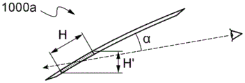
Preferably, the first marking (OLED) is nested (inscribed) in a rectangle having a centimeter-level vertical dimension or height H (the horizontal dimension of which is referred to as the width W) and defining an angle α between the windshield and the driver's (or passenger's) line of sight, the first marking (OLED) being characterized by a vertical dimension referred to as the apparent height H ' and by the formula setting H, defining what is referred to as the apparent height HMaking a vertical dimension of the apparent height H' and passing the formula H is set.
For example, for a marker (OLED) with an apparent height H' of 2 cm (target) and for an angle of 25 °, H is 4.7 cm. The correction by distortion (anaphorphosis) can therefore be large.
For example, the first marker (OLED) may be nested in a square or rectangle having H (or better H ') and W (or better W') of 1 to 10 centimeters, better still 2 to 5 centimeters.
To a lesser extent, it is also possible to attempt to compensate for the perspective effect by widening the bottom of the first sign relative to its top by a factor (1+ H'/(d tan (α))), where d is the distance between the driver (or passenger) and the first sign.
The position of the first logo and even the second logo or the plurality of logos each formed by an OLED device may be:
along the lower longitudinal edge (in the mounted position), in particular on the driver's side, in particular when the sign is a driving assistance sign (graphic symbol, etc.) requiring a quick reaction from the driver;
alternatively or cumulatively, along the upper longitudinal edge (in the mounted position), in particular when the graphic symbol is a driving assistance sign or information about the vehicle state;
alternatively or cumulatively, along the driver-side lateral edge (in the mounted position), in particular when the graphic symbol is a driving assistance sign or information about the vehicle state;
alternatively or cumulatively, along the passenger side transverse edge (in the mounted position), in particular for the graphic symbols relating to the passenger.
The first marker is selected from;
-a driving assistance sign, preferably at the lower longitudinal edge;
-a status indicator indicating the operating status of the vehicle, preferably on the lower longitudinal edge, the upper longitudinal edge or the driver's side lateral edge;
-with respect to the external environment: information on weather, etc.; and
-an indicator indicating connectivity to the communication network, in particular at the front passenger side transverse edge.
The first indicia may be over the first non-porous region of the inner masking layer. It may be desirable to increase the width of the imperforate area locally to enable the driver (or co-driver) to better see the first sign (without reducing his gaze too much). Furthermore, the inner masking layer may be a particularly longitudinal or transverse driver (or passenger) side strip (made of glaze, on face F3 or F4) having a width L0 of at most 2, 5, 10, 20 cm or 30 cm and a width L1> L0 in the region of the first sign.
The first marking may be in the visual zone or in the imperforate zone and adjacent to the discontinuous (decorative) inner masking zone adjacent to the first imperforate zone, in particular in the form of a set of decorative patterns (typically of sub-centimetre scale and spaced 0.01 to 2 centimetres apart), in particular made of enamel (the same enamel as the imperforate zone). For example, the patterns have decreasing size towards the middle of the vision zone and/or increasing pitch towards the middle of the vision zone.
The inner masking layer may be a strip along one edge of the windshield.
The first OLED device is capable of emitting a first emission, such as a red, green, orange or white emission at time t1 and a second, different emission, such as a red, green, orange or white emission at time t2, in accordance with a control signal.
The windscreen may comprise a color filter, such as a color filter layer, on the first OLED device, which particularly emits white light, or on the top or bottom surface of the protective element, particularly in the through-holes of the optional top masking layer.
Colored OLEDs can also be used with them in cases where their emission spectrum does not directly allow to obtain a given color coordinate (as set in, for example, a standard, or as required by the car manufacturer). For example, the color filter can then filter out at least some of the emission spectrum when it is too broad.
The color filter preferably comprises a color filter layer on the first (bottom-emitting) OLED device or on the protective top element (top or bottom surface).
Various types of filters (with different compositions and different operating modes) can be used that act on or change the light emission of the OLED device (in particular, their light transmission has a different spectral dispersion than the light emission of the OLED device) in a selected, characteristic and reproducible manner. As explained below, these filters may be tinted transparent polymers, tinted glass (by deposition or achieving tinting in its bulk), or may be layers deposited on OLEDs and the like.
As mentioned above, one or more absorption filters (this absorption being controlled in particular by inorganic or organic compounds added as appropriate to a matrix made of glass or made of plastic). Filters of this type may be formed, for example, by depositing one or more organic or inorganic pigments or dyes (optionally dissolved or dispersed in a medium, such as in particular a silicone, epoxy or acrylic resin, UV-curable ink or mineral sol-gel matrix) on the surface (on the top face) of a transparent support element, such as a common carrier. Such an element may be a glazing material (soda lime glass, borosilicate glass or plastics/polymers (sheets of polyethylene terephthalate, in particular heat-stabilised polyethylene terephthalate, polycarbonate, acrylate, Polyetheretherketone (PEEK) etc.)). Examples of such Filters are in particular gelatin Filters or polymer color Filters sold by Lee Filters or Rosco. The deposition can be carried out by screen printing, by inkjet or laser printing, by spray coating, by dip coating, by roll coating, etc., preferably by screen printing or inkjet printing, in particular on glass and/or OLED devices, particularly and advantageously by inkjet printing.
Note that the colored substance (particularly, dye or pigment) used for manufacturing the above-described optical filter is heat-resistant. For example, it may be advantageous to use optionally polychlorinated copper phthalocyanine pigments, which are mixed and dispersed in a resin, in particular a crosslinkable silicone resin, for example (and advantageously) applying the mixture, in particular by screen printing. In the case of ink-jet printing, the inks used are in particular UV-curable inks which are stable to temperature and light, for example Anapurna M ink sold by Agfa.
The absorption filter is advantageously capable of obtaining a selected effect or color, regardless of the angle of incidence of observation.
In another embodiment, one or more filters operating by light reflection (this reflection being controlled in particular by interference taking place within a stack of thin layers made of various materials, a thin layer being a layer whose thickness is less than the wavelength of the light) are used, in particular dichroic filters, filters based on a (laminar) semi-reflective interference stack, etc. Such filters are for example manufactured by alternating (vacuum) Physical Vapour Deposition (PVD) (sputtering, magnetron sputtering, evaporation) or Chemical Vapour Deposition (CVD) of high and low refractive index layers, the substrate on which the deposition is performed may be a glazing material or a polymer.
The reflective filter is capable of achieving a selected effect or color on the driver's visual axis, but the perceived effect or color may be different at another angle of incidence.
The first OLED device preferably comprises in this order:
-a substrate (which is preferably dielectric, in particular transparent: plastic or glass film);
-optionally one or more functional layers:
a moisture barrier layer (if the substrate is plastic) or an alkali metal barrier layer (if the substrate is glass),
and/or a light extraction layer, a scattering layer, for example a glaze or another mineral (sol-gel, etc.) or an organic binder containing scattering particles if a glazing substrate is fitted, or an organic (resin) or mineral (sol-gel) binder containing scattering particles if a plastic substrate,
-a preferably transparent lower electrode (anode);
a first organic light emitting system (a plurality of emitters of various colors can be stacked);
and preferably a reflective upper electrode, in particular a metal (silver, aluminum, etc.); and optionally a cover layer, such as an encapsulating layer (e.g., a polymeric deposit or film, e.g., glued to the upper electrode, etc.).
This cover layer may be glued to face F4 or against face F4 (F4 with or without a masking layer).
If a second OLED device is used in conjunction with facet F4, it may have the same structure and may include in particular:
a substrate (which is preferably dielectric, particularly transparent: glass or plastic film) which is a first substrate (common substrate) or a second, different (adjacent) substrate;
-optionally one or more functional layers:
a moisture barrier layer (if the substrate is plastic) or an alkali metal barrier layer (if the substrate is glass),
and/or a light extraction layer, a scattering layer, for example a glaze or another mineral (sol-gel, etc.) or an organic binder containing scattering particles if a glazing substrate is fitted, or an organic (resin) or mineral (sol-gel) binder containing scattering particles if a plastic substrate,
-a preferably transparent lower electrode (anode);
a second organic light-emitting system of the same or different color as the first system (a plurality of emitters of various colors may be stacked);
-a preferably reflective upper electrode; and
optionally a cover layer, such as an encapsulation layer (e.g. a polymeric deposit or film, e.g. glued onto the upper electrode, etc.).
The first and second OLED devices can in particular be adjacent and on a common carrier (plastic film, in particular for protecting and/or carrying electrical conductors, etc.) on the substrate side or on the upper electrode side (on the electrodes or on the cover layer).
Various types of OLEDs are known:
bottom-emitting or in other words substrate-emitting OLEDs (emission through a transparent substrate), the lower electrode being transparent and the upper electrode being reflective;
top-emitting OLEDs (output via the upper electrode), the lower electrode being reflective and the upper electrode being transparent; and
bottom-emitting and top-emitting OLEDs using transparent or semi-transparent electrodes.
It is preferred to use a bottom emitting first OLED device, i.e. a device that emits from the bottom, so that the substrate is on the same side as the protective top element.
Each (preferably lower) transparent electrode may be a metal grid, for example made of silver, with a suitable width, or a transparent conductive layer, such as a layer of a Transparent Conductive Oxide (TCO), or a thin-layer stack with at least one (thin) metal layer, in particular a silver layer, between two dielectric layers, for example layers of one or more metals (Sn, Zn, etc.) or oxides and/or nitrides of silicon.
The first OLED device may have one or more technological edges for supplying power at the periphery of the emission region (non-emission region), typically consisting of one or more strips, in particular at the sides of the emission region. Such a technical edge may be a current distribution area. The technical edge may have a width W2 of at most 2 cm, preferably at most 1 cm or even at most 6 mm or 5 mm.
It is desirable for the first indicia and the adjacent second and other indicia to be aligned in a single row rather than stacked in the top masking zone.
Preferably, the top masking layer (preferably made of glaze) masks one or more technical edges of the first OLED device, even masking: any electrical conductor (not otherwise visible), i.e. a connection, such as a cable, one or more electrical wires, an electrically conductive film, etc., present between the face F4 and the bottom face of the top element and connected to the first OLED device.
Preferably, the (width) of the first OLED device extends beyond the through hole, for example by at least 5 mm, even by at least 1 cm, so that the light emitting area of the OLED easily faces the through hole.
In a given peripheral zone, it may be desirable to have multiple lighted signs (graphic symbols, etc.) side-by-side (e.g., aligned or in a corner of a windshield, etc.).
The general shape of the protective top element and/or the carrier film may be a rectangular strip along a first (longitudinal or transverse) edge, optionally L-shaped (for corners) or L-shaped and thus having a dog-legged portion for electrical connection protruding from the edge face of the glazing.
The protective top element and/or the carrier film advantageously contribute to:
easier handling and assembly of a set of pre-installed OLEDs;
easier manufacturing of the electrical connection;
as mechanical reinforcement.
The protective top or bottom film may carry one or more first electronic elements, including a first microcontroller (driver) addressing the first OLED device and regulating the power supply (preferably current) to the first OLED device and even one or more second electronic elements, including a second microcontroller addressing the second OLED device and regulating the power supply (preferably current) to the second OLED device.
Each microcontroller recognizes in the control signal whether an instruction is directed to its dedicated flag and adjusts the level (e.g., the magnitude of the current) accordingly.
For each OLED on the common carrier there are preferably two electrical conductors for the control sign decoded by the dedicated microcontroller and two electrical conductors for the power sign connected to the microcontroller.
Means for modulating the power of the OLEDs may be provided between at least two configurations: night driving configuration, wherein the power of the first OLED device is adjusted so that the brightness of the first sign is typically at about 30 and about 100 Cd/m2And a daytime driving configuration, the power of the first OLED device is adjusted so that the brightness of the first sign is typically between about 200 and about 2000Cd/m2In the meantime. During the daytime, it is also possible to adjust the brightness according to the external lighting conditions, in particular with sensors sensing natural light in the windshield or elsewhere in the vehicle: if the sunlight is very abundant, the OLED is made to emit strongly, if cloudy, less strongly to avoid glare.
The thermoformable material used to make the interlayer is selected from polyvinyl butyral (PVBs), such as RC41 from Solutia or Eastman, plasticized polyvinyl chloride (PVCs), Polyurethane (PU) or Ethylene Vinyl Acetate (EVAs). The thermoformable material is preferably polyvinyl butyral (PVB), optionally having a wedge-shaped cross-section that decreases from the top to the bottom of the laminated glazing.
In the case of an additional head-up display (HUD), the laminated interlayer may have a wedge-shaped cross-section that decreases from the top to the bottom of the laminated windshield, in particular, to avoid ghosting.
It may be desirable to maintain the acoustic properties of the windshield. The laminate interlayer may thus comprise at least one so-called interlayer made of a viscoelastic plastic having sound and vibration damping properties, in particular based on polyvinyl butyral and a plasticizer, the interlayer further comprising two outer layers made of standard PVB, the interlayer being between the two outer layers. To use a HUD-type head-up display, one or both of the outer layers optionally has a wedge-shaped cross-section decreasing from the top to the bottom of the laminated glazing, the viscoelastic plastic layer having acoustic vibration damping properties having a cross-section that is constant from the top to the bottom of the laminated glazing.
The inner (or outer) masking layer may be a black enamel layer, a lacquer layer or an opaque ink, preferably on face F2 (or F3 or F4) or on a lamination interlayer or even on an additional (PET or the like) carrier film.
Advantageously, the outer and inner masking layers are made of the same material (preferably a glaze, in particular a black glaze) and are on F2 and F3 or on F2 and F4.
The first glazing and the second glazing may be parallelepipeds, having panels (pans) or main faces of rectangular, square or even any other shape (circular, oval, polygonal). The dimensions may be large, for example having an area greater than 0.5 or 1 square meter.
The first and/or second glazing may (depending on aesthetic performance or desired optical effect) be clear glass (light transmission T at 4 mm thickness)LGreater than or equal to 90%), for example glass of standard soda-lime composition, such as Planilux from Saint-Gobain glass, or ultraclean glass (T at 4 mm thickness)LGreater than or equal to 91.5%), e.g. containing less than 0.05% Fe III or Fe2O3Of soda-lime-silica Glass, e.g. Diamant Glass from Saint-Gobain Glass or Diamant GlassGlass Optiwhite from Pilkington or glass B270 from Schott or another composition of glass described in the document WO 04/025334.
The Glass of the first and second glazing may be neutral (colourless) or (slightly) coloured, in particular grey or green, such as Glass venus or TSA from Saint-Gobain Glass. The glass of the first and/or second glazing may be subjected to a chemical or thermal treatment, such as toughening, annealing or tempering treatment (particularly to obtain better strength) or semi-tempering.
The light transmission T can be measured according to the standard ISO 9050:2003 using the light source D65LAnd taking into account the total transmission of the direct and possibly diffuse transmission (in particular integrated over the visible range and weighted by the sensitivity curve of the human eye), for example using a spectrophotometer equipped with an integrating sphere, and then, if necessary, converting the measurement at a given thickness to a reference thickness of 4 mm according to the standard ISO 9050: 2003.
For windshields, TLIt may be preferred to be at least 70%, even at least 75%.
In one embodiment, the first glazing is made of inorganic glass and the second glazing is made of organic glass (such as PC, PMMA, Cyclic Olefin Copolymer (COC) or even polyethylene terephthalate (PET)), optionally protected by a coating (on face F4).
The outside glazing may comprise a thin functional layer on one or even both of its faces F1 and F2: mention may be made of a hydrophobic or self-cleaning photocatalytic layer on face F1 and a layer or stack of thin layers reflecting solar radiation on face F2 (and intended to form one or more capacitive sensors, antennas, etc.).
In order to limit the heating of the passenger cabin or to limit the use of air conditioning, at least one of the glazing units (preferably the outside glazing) is tinted, and the laminated glazing unit may also comprise a layer reflecting or absorbing solar radiation, preferably on face F4 or on face F2 or F3, in particular:
a transparent conductive oxide layer (on face F4), called TCO layer, or a thin-layer stack comprising at least one TCO layer;
-a stack of thin layers (on F2 or F3) comprising at least one silver layer, the or each silver layer being deposited between the dielectric layers.
Both a (silver-containing) layer and a TCO layer may be arranged on the faces F2 and/or F3, respectively, on F4.
The TCO layer (transparent conductive oxide layer) is preferably fluorine-doped tin oxide (SnO)2F) or an indium tin oxide layer (ITO). For layers made of ITO, the thickness is typically at least 40 nm, or even at least 50 nm, or even at least 70 nm, typically at most 150 nm or at most 200 nm. For fluorine doped tin oxide layers, the thickness is typically at least 120 nm, or even at least 200 nm, typically at most 500 nm. For example, the low-emissivity layer comprises the following sequence: high index sublayer/low index sublayer/TCO layer/optional dielectric cap layer. As preferred examples of low-emissivity layers (protected during tempering), the following can be chosen: high index sublayer (<40 nm)/low index sublayer (<30 nm)/ITO layer/high index capping layer (5-15 nm)/low index barrier capping layer ((ii) ((iii))<90 nm)/Final layer (<10 nm). As low-emissivity layer, mention may be made of the layers described in patent US 2015/0146286, on face F4, in particular in examples 1 to 3.
The face F3 may thus comprise a heating layer, preferably neutral in transmission, optionally under an inner masking layer on F3, above which there are first and second current distribution strips, generally on the first and second longitudinal sides and particularly opaque and made, for example, of a glaze containing silver.
Furthermore, the first flag, in particular when it is on the first longitudinal side, may be separated from the opaque first current distribution strip of the heating layer on F3. The first current distribution bar may be more central than the first flag.
The transparent conductive layer on F4 can be used to supply power to the OLED.
The (optional) transparent conductive layer on F4 or F3 can be used as a touch button for an OLED.
The distance D between the (longitudinal) edge of the glazing and the bottom of the first marker OLED may be at least 5 cm, 8 cm, 10 cm. The distance between the (longitudinal) edge of the glazing and the bottom of the first marker OLED may be at most 25 cm, even at most 20 cm.
The invention and its advantages are better understood on reading the following description of non-limiting embodiments, which is given below with reference to the following drawings.
FIG. 1 shows a side elevational view of a passenger compartment of a first windshield incorporating an internally illuminated sign according to the present invention.
Fig. 1' shows a side elevational view of a passenger cabin including a second windscreen incorporating an internally illuminated sign in accordance with the invention.
Fig. 1 ″ shows a partial cabin side elevation view of a third windshield comprising an internally illuminated sign according to the invention.
FIG. 1i is a side view showing the tilt angle of a windshield having an internally illuminated emblem according to the invention, and FIG. 1j shows the emblem stretched in the vertical direction to compensate for the tilt effect.
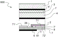
FIG. 2 shows a partial cross-sectional view of a laminated windshield incorporating one or more internally illuminated signs according to the present invention.
FIG. 3 shows a partial cross-sectional view of a laminated windshield incorporating one or more internally illuminated signs according to the invention.
FIG. 4 shows an exploded partial longitudinal cross-sectional view and FIG. 4a is a connection thereof of a laminated windshield including one or more internally illuminated signs according to the present invention.
FIG. 5 shows an exploded partial transverse cross-sectional view of a laminated windshield incorporating one or more internally illuminated signs according to the present invention.
FIG. 6 shows an exploded partial transverse cross-sectional view of a laminated windshield incorporating one or more internally illuminated signs according to the present invention.
FIG. 7 shows an exploded partial longitudinal cross-sectional view of a laminated windshield incorporating one or more internally illuminated signs according to the present invention.
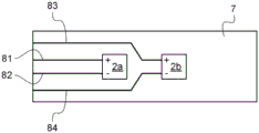
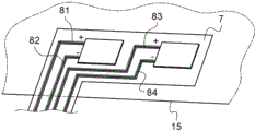
Fig. 8a shows a front view of a common carrier carrying two OLED devices forming a luminous sign and carrying current distribution conductors on a windscreen.
Fig. 8b shows a front view of a common carrier carrying two OLED devices forming a luminous sign and carrying distribution conductors on a windscreen.
Fig. 8c shows a front view of a common carrier carrying two OLED devices forming a luminous sign and carrying current distribution conductors on a windscreen.
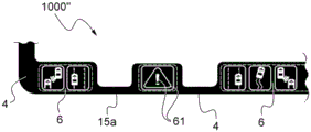
FIG. 1 shows a passenger side elevation view of a windshield incorporating an internally illuminated sign according to the present invention.
The windscreen 1000 is laminated and comprises a first curved outer glazing having main faces F1 (outermost) and F2, a polymeric laminating interlayer made of a material such as PVB, and a second curved inner glazing 1' having main faces F3 and F4 (innermost).
It has a rectangular shape delimited by its lateral sides 15c and 15d and longitudinal sides 15a and 15b and has an opaque perimeter, here black, on face F2 and on face F3 or on faces F2 and F4 or even only on faces F2, F3 or F4.
The inner masking layer 4 is opaque and may be made of black glaze deposited on face 13 or F3 or face 14 or F4 of the inner glass 1', of paint or optically opaque ink deposited on the polymer interlayer, or of an additional, coloured or painted, opaque polymer layer laminated between the inner glass and the interlayer.
This layer is deposited using any technique known to those skilled in the art, such as, without limitation, screen printing techniques, ink jet printing techniques, or even rotogravure, flexographic, or lithographic techniques.
The curved organic light emitting diode device, referred to as OLED device, which is combined with the face F4 on the outer periphery and face F4 side, is here above the area of the inner and outer masking layers 4, 4 '(as a variant, there may be layer 4 or layer 4'). They are capable of emitting a first emission in the visible spectrum and form a luminescent marking.
Each OLED device is behind (against or fixed to) a top element, called protective top element 7, which is preferably dielectric and transparent, farther from the second glazing than the OLED device and is a thin glass or polymeric transparent curved film. The top element, referred to as the protective top element, carries on its major bottom 71 or major top 72 surface one or more first discontinuities 61 in a layer referred to as the top masking layer 6 to form vias that keep the OLED signals visible.
Along the lower longitudinal edge 15a (in the installed position), in particular on the driver side, there are a plurality of signs each formed by a dedicated OLED device, in particular if the sign is a driving aid sign (requiring a quick response by the driver). For example, the OLED device is behind (against or fixed to) the protective top element 7.
Mention may be made of:
an indicator (letter "SPEED") indicating overspeed, which lights up an optional red or an optional orange when the limit is almost reached;
a frontal collision prevention diagnosis, which lights up, for example, when the vehicle is too close to the front vehicle (car, motorcycle, etc.) (i.e. does not comply with the stopping distance);
a hazard warning lamp which lights up when there is a hazard.
Along the upper longitudinal edge 15b (in the mounted position), in particular in a central position conventionally used for fixing the rear view mirror, there are a plurality of signs each formed by a dedicated OLED device, for example behind (against or fixed to) the protective top element 7.
Along the left lateral edge 15c (in the mounted position) there are a plurality of markers each formed by a dedicated OLED device, for example behind (against or fixed to) the protective top element 7.
Mention may be made of:
-graphic symbols regarding the vehicle status: oil level, temperature, unclosed door, no safety belt fastening;
-a graphical symbol as to whether the headlight is turned on or not.
Along the right lateral edge 15d (in the mounted position) there are a plurality of markers each formed by a dedicated OLED device, for example behind (against or fixed to) the protective top element 7.
Mention may be made of:
graphic symbols relating to the door (not closed), the safety belt (not tied);
-graphic symbols regarding air conditioners, fans;
-a graphical symbol of information about the external environment, an indicator indicating a location of a friend in the vicinity of the vehicle;
-an indicator indicating connectivity to the telecommunications network.
The width of the enamel band 4 is reasonably wide in the sign area.
Fig. 1' shows a side elevational view of a passenger cabin including a second windscreen incorporating an internally illuminated sign in accordance with the invention.
Along the lower longitudinal edge 15a (in the mounted position) on the driver's side there are a plurality of signs each formed by a dedicated OLED device, for example behind (against or fixed to) the protective top element 7.
Mention may be made of:
a left-hand collision prevention diagnosis, which is for example illuminated when a passing vehicle and/or a vehicle of the left lane are too close;
a right-hand collision prevention diagnosis, which is for example lit when the vehicle in the right lane is too close;
a lane position diagnostic, which for example lights up when the driven vehicle is too far to the left or too far to the right in its lane.
The protective top element 7 may be L-shaped to cover the sides of one corner, here for example the left lateral side 15c and the upper longitudinal side 15 b.
In the visual area, adjacent to the border of the top masking layer, a system comprising optional transparent base films/ OLEDs 2c and 2 d/transparent top protective elements 7a (which may extend over the inner and/or outer masking zone on the lateral and/or longitudinal edges, curved or not) may be arranged. The current-supply conductors are chosen to be made of a transparent material or a more opaque material (metal, etc.) whose width is sufficiently thin (for example less than 1 mm or 0.8 mm) -the line or track-so as to be (quasi) invisible. The transparent protection element 7a may extend over the inner and/or outer masking zone and protect one or the other OLED sign. The same applies to the optional carrier film, etc.
Fig. 1 ″ shows a partial cabin side elevation view of a third windshield comprising an internally illuminated sign according to the invention.
The graphic symbol, here for example a hazard warning lamp, can be separated from the other graphic symbols by the additional thickness of the glaze 4 behind this graphic symbol. This first OLED device is here mounted on face F4, for example, together with a separate protective top element 7, said element 7 being common with other OLED devices as a variant.
Fig. 1i is a side view showing the steep inclination of a windscreen with an internally illuminated sign according to the invention having an actual height H and an apparent height H' (as perceived by an oppositely located driver).
For example, angle α is approximately 25 °.
In addition, FIG. 1j shows a logo stretched in the vertical direction to compensate for tilt effects.
Fig. 2 shows a partial transverse cross-sectional view of a laminated windshield 200 containing one or more internally illuminated signs according to the present invention.
A laminated vehicle windshield 200 including one or more internally illuminated signs includes:
a first curved glazing, preferably made of inorganic glass and optionally coloured, in particular grey or green, having a first main face referred to as F1 and an opposite second main face referred to as F2, intended to constitute the outside of the vehicle, the thickness E1 of said glazing preferably being at most 2.5 mm, even at most 2 mm-in particular 1.9 mm, 1.8 mm, 1.6 mm and 1.4 mm-or even at most 1.3 mm or at most 1 mm, this glazing being made, for example, of TSA glass and having a thickness of 2.1 mm;
a second curved (like the first glazing) glazing, preferably made of inorganic glass, having a third main face, called F3, and an opposite fourth main face F4, intended in particular to constitute the inside of the vehicle, the thickness E '1 of which is preferably less than E1, even at most 2 mm-in particular 1.9 mm, 1.8 mm, 1.6 mm and 1.4 mm-or even at most 1.3 mm or at most 1 mm, the total thickness E1+ E'1 of the glazing being preferably strictly less than 4 mm, even less than 3.7 mm, this glazing being made, for example, of TSA glass and having a thickness of 2.1 mm,
said first and second glazing are joined together via faces F2 and F3 by a laminated interlayer made of (clear or ultra clear) thermoformable and preferably thermoplastic polymeric material, even PVB, and having a (total) thickness E3 of at most 2.2 mm, better at most 2 mm, at most 1.5 mm or even at most 1 mm, said interlayer being made of 1, 2 or 3 sheets and being set back in particular from the edge face of the second glazing (at most 5 mm or even at most 2 mm or at most 1 mm) and even from the edge face of the first glazing (at most 5 mm or even at most 2 mm or at most 1 mm), said interlayer having a first main bonding face (face F2 side) and a second main bonding face (face F3 side);
a first peripheral layer, called inner masking layer 4, made of opaque material, which extends along the border of face F3, on face F4, in particular along the border of face F4, in particular (directly) on face F4;
and/or a second peripheral layer, called outer masking layer 4', made of opaque material, on face F2, facing the inner masking layer and extending along the border of face F2.
The inner 4 and outer 4' masking layers are made of the same material and are preferably made of glaze. A functional layer, such as a transparent conductive layer, may be on side S3 and act, for example, as a solar or heating (anti-fog, etc.) layer.
A first curved organic light emitting diode device 2a, called OLED device, is peripherally bonded to face F4 and on the face F4 side, here over the area of the inner and outer masking layers 4, 4 '(as a variant, there may be layer 4 or layer 4').
The first OLED device is capable of emitting a first emission in the visible spectrum and forms a first indicia 61. Adjacently there is a thin second curved organic light emitting diode device 2b, called OLED device, having the same dimensions as 2 a. The second OLED device is capable of emitting emission in the visible spectrum and forms a second indicia 61.
The OLED devices 2a and 2b are behind (against or fixed to) a top element called a protective top element 7, which is preferably dielectric and transparent, farther from the second glazing than the OLED devices and is a thin glass or polymeric transparent curved film. The top element, called protective top element, carries on its major bottom face 71 or major top face 72 a first discontinuity 61 in a layer, called top masking layer 6, 60, which forms a window of the OLED flag.
The OLED devices 2a and 2b preferably have a sub-centimeter thickness E2, even at most 0.5 millimeter thick, and more preferably at most 0.35 millimeter thick.
The protective top element 7 is for example a (flexible) thin polymeric film, in particular a film made of PET, polyimide, polycarbonate, acrylic, PEN or PEEK, while the top masking layer may be a sol-gel layer, a lacquer or a varnish having preferably the same color as the inner and/or outer masking layers.
The protective top element 7 is for example made of a particularly tempered glass, while the top masking layer may be a sol-gel layer, a paint, a varnish or a glaze, particularly identical to that or those on the windscreen or at least preferably of the same colour.
For fixing the protective top element 7, a double-sided adhesive tape 7 '(on the sides of the OLEDs) is used, having a top face 72' on the side of the face 71 and a bottom face against the protective bottom element 5, such as the (laminated) film 5, the bottom face 51 being optionally glued to the face F4 (on the optional layer 4 ') and the top face 52 on the side of the double-sided adhesive tape 7'. The carrier film 5 is, for example, a (flexible) thin polymeric film, in particular a film made of PET, polyimide, polycarbonate, acrylate, PEN or PEEK.
The base film 5 and/or the protective element 7 may carry electrical conductors that supply power to, inter alia, OLEDs or form touch buttons, for example capacitive touch buttons. These conductors are insulated by dielectric double-sided tape.
As shown in the detailed view, when the OLED emits white light, a color filter 9a may be added on the bottom surface 71 or on the OLED in addition thereto.
Fig. 3 shows a partial transverse cross-sectional view of a laminated windshield incorporating one or more internally illuminated signs 300 according to the present invention.
Which differs from the windshield 200 in the absence of a basement membrane. The OLEDs 2a and 2b are glued to face F4 or against face F4 (optional layer 4 is present).
Fig. 4 shows an exploded partial longitudinal cross-sectional view of a laminated windshield 400 containing one or more internally illuminated signs according to the present invention (the elements are not drawn as curved surfaces, i.e., have curvature, for simplicity).
The first and second LED devices 2a and 2b are selected to be bottom emission type devices (emitting through their bases) and each include:
a first curved transparent substrate 20, for example plastic (PET or the like) or (tempered) glass, carrying:
a transparent lower electrode (closest to the substrate) 21, for example made of ITO or a metal (silver, etc.) grid
A first organic light emitting system 22;
a reflective electrode called the upper electrode (furthest from the substrate) 23 and made, for example, of aluminum or silver; and
optionally a protective film 24, for example kapton, glued to the upper electrode and optionally extending beyond the upper electrode and having electrode contacts (on the given sides 21a, 23 a).
The bottom face 71 is glued to the OLEDs by means of double-sided glue 90a, 90 b.
The bottom element 5 is a double-sided tape for gluing the assembly consisting of the top element 7 and the OLEDs 2a, 2b to the face F4.
If the element 5 is cut to place the OLEDs, the bottom side (24 side) of the LEDs may be against the face F4 (layer 4).
In connection with this connection, as shown in fig. 4a, a flexible printed circuit board 25, a so-called PCB as is conventional (which is made of plastic and has in particular 8 tracks), can be used. Which may be between the OLED devices 2a and 2b and in the protective resin. Which may have the same thickness as OLEDs.
Fig. 5 shows an exploded partial longitudinal cross-sectional view of a laminated windshield 500 containing one or more internally illuminated signs according to the present invention (the elements are not drawn as curved surfaces, i.e., have curvature, for simplicity).
The connection is for example achieved by a set of wires or flat connectors between the OLED devices and extending beyond the edge face of the glazing.
Fig. 6 shows an exploded partial longitudinal cross-sectional view of a laminated windshield 600 containing one or more internally illuminated signs according to the present invention (the elements are not drawn as curved surfaces, i.e., have curvature, for simplicity).
The OLEDs 2a and 2b are glued on the bottom face 71 of the protective top element by means of a double-sided glue 7'. Such an adhesive has holes for electrical contacts between the OLED 2 and the layer 8, which contacts are formed, for example, by pads 26.
Fig. 7 shows an exploded partial longitudinal cross-sectional view of a laminated windshield 700 containing one or more internally illuminated signs according to the present invention (the elements are not drawn as curved surfaces, i.e., have curvature, for simplicity).
The laminated windshield 700 differs from the windshield 600 in that the double-sided tape 5 is moved to the top surface side.
The OLEDs 2a and 2b are glued on the bottom face 71 of the protective top element by means of a double-sided glue 7'. Such an adhesive has holes for electrical contacts between the OLED 2 and the layer 8, which contacts are formed, for example, by pads 26.
Fig. 8a shows a front view of a common carrier 7, which is a top element or even a bottom film or even a face F4, carrying two OLED devices 2a and 2b forming a luminous sign (picto et al) and carrying conductors for distributing current to the windscreen. It concerns an area of an electrically conductive (metal, TCO, etc.) layer 8 with four electrically insulated wires 80.
Fig. 8b shows a front view of a common carrier 7, which is a top element or even a bottom film or even a face F4, carrying two OLED devices 2a and 2b forming a luminous sign (picto et al) and carrying conductors for distributing current to the windscreen. It involves four, for example, metal, e.g. copper, conductive tracks 81 to 84, which may or may not be visible.
Fig. 8c shows a front view of a common carrier 7, which is a top element or even a bottom film, carrying two OLED devices 2a and 2b forming a luminous sign (picto et al) and carrying conductors for distributing the current to the windscreen. It involves four, for example copper, conductive tracks 81 to 84, which may or may not be visible. The carrier also has a fold line portion extending beyond the edge face 15.
Claims (20)
1. A laminated vehicle windshield comprising one or more internally illuminated signs comprising:
-a first curved glazing having a first main face and an opposite second main face, the first main face being intended on the outside of the vehicle;
a second curved glazing having a third main face and an opposite fourth main face, the fourth main face being intended on the inside of the vehicle, at least one of the first and second curved glazings being made of an inorganic glass,
the first and second curved glazing panels being joined together via the second and third major faces by a laminated interlayer made of a thermoformable polymeric material, the laminated interlayer comprising a first adhesive major face facing the second major face side, and a second adhesive major face facing the third major face side; and
-a first light source for a first sign;
wherein the first light source comprises a first curved Organic Light Emitting Diode (OLED) device bonded to the fourth major face and on a periphery of the fourth major face side, and wherein the first curved OLED device is configured to emit a first emission in the visible spectrum and form a first indicia,
and wherein the first curved OLED device is farther from the second curved glazing than the first curved OLED device behind the protective top element.
2. The laminated vehicle windshield as recited in claim 1 further comprising a first peripheral layer made of an opaque material forming an inner masking layer between the second adhesive face and the third major face or on the fourth major face and/or a second peripheral layer made of an opaque material forming an outer masking layer between the first adhesive face and the second major face, wherein when the first curved OLED device is over the inner and/or outer masking layer area, the protective top element is a curved film carrying a top masking layer made of an opaque material on its major bottom or top face with a first channel discontinuity to keep the first indicia visible.
3. The laminated vehicle windshield as recited in claim 1, wherein the first curved OLED device is in the vision area, wherein the electrical connections of the first curved OLED device are invisible or transparent.
4. The laminated vehicle windshield as recited in claim 3, wherein the protective top element is a curved film that extends beyond one or more edges of the first curved OLED device, and a second curved OLED device is adjacent the first curved OLED device and forms a second logo comprised of one or more symbols and/or one or more letters, the second logo being adjacent the first logo, and a major bottom face of the protective top element is glued to the fourth major face behind the protective top element by glue or double sided glue.
5. The laminated vehicle windshield as recited in claim 1 further comprising a second curved Organic Light Emitting Diode (OLED) device bonded to the fourth major face, the second curved OLED device being different from the first curved OLED device and forming a second indicia of one or more symbols and/or one or more letters, the second indicia being adjacent to the first indicia, and the first and second curved OLED devices being on a common carrier made of a curved film that:
arranged at the top side and thus the light emission side,
or on the fourth main face, arranged on the bottom side and thus on the side opposite to the light emission side.
6. The laminated vehicle windshield as recited in claim 5, wherein the protective roof element carries an electrical conductor through its bottom surface that supplies power to the first curved OLED device and the second curved OLED device, or wherein the base film carries an electrical conductor through its top surface that supplies power to the first curved OLED device and the second curved OLED device.
7. The laminated vehicle windshield as recited in claim 5, wherein the protective roof element carries an electrical conductor through its underside that supplies electrical power to the first curved OLED device and the second curved OLED device.
8. The laminated vehicle windshield as recited in claim 1, wherein the protective roof element is selected from polymeric film or glass and/or the primary film between the fourth major face and the first curved OLED device is selected from polymeric film or glass.
9. The laminated vehicle windshield as recited in claim 1, further comprising a second curved Organic Light Emitting Diode (OLED) device on the fourth major face, the second curved OLED device configured to illuminate a second indicia, the second indicia comprised of one or more symbols and/or one or more letters, adjacent the first indicia, wherein the first and second curved OLED devices are between:
-a curved bottom element, which is therefore the side opposite to the light emission side, glued onto the fourth main face and selected from double-sided glues, and a film carrying the first electrical conductor on the top face, i.e. on the same side as the first and second curved OLED devices;
-and a protective top element, which is a curved membrane optionally carrying a second electrical conductor on its bottom surface.
10. The laminated vehicle windshield as recited in claim 9, wherein the first conductor is for supplying power to the first and second curved OLED devices, and the second conductor forms a touch button of the first curved OLED device.
11. The laminated vehicle windshield as recited in claim 1, wherein the first curved OLED device is mounted on the fourth major face directly or via a common carrier with a second curved OLED device adjacent the first curved OLED device and configured to illuminate a second indicia comprised of one or more symbols and/or one or more letters adjacent the first indicia, and the fourth major face is optionally coated with an inner masking layer or the common carrier carries an electrical conductor that supplies power to the first curved OLED device and the second curved OLED device.
12. A laminated vehicle windscreen according to claim 11, wherein the electrical conductor of the first curved OLED device is protected by a varnish or resin or even completely encapsulated in a protective dielectric material at most 0.5 mm thick, which is glued onto the fourth main face and onto the protective top element completely directly or via the carrier film.
13. The laminated vehicle windshield as recited in claim 1 further comprising a color filter on the first curved OLED device or on the top or bottom surface of the protective element.
14. The laminated vehicle windshield as recited in claim 1, wherein the first indicia is nested in a rectangle having a centimeter-scale vertical dimension or height H and thereby defines an angle α between the windshield and the driver's line-of-sight axis, the first indicia being characterized by a vertical apparent height H' and being formulated H is set.
15. The laminated vehicle windshield as recited in claim 1, wherein the first indicia is selected from the group consisting of:
-a driving assistance flag;
-a status indicator indicating an operating status of the vehicle;
-a piece of information about the external environment;
-an indicator indicating connectivity to the communication network.
16. The laminated vehicle windshield as recited in claim 1, further comprising a first peripheral layer forming an inner masking layer, the first curved OLED device being over the inner masking layer area, the inner masking layer being a strip having a width L0 and in the area of the first indicia having a width L1> L0.
17. The laminated vehicle windshield as recited in claim 1 wherein the first curved OLED device bonded to the fourth major face comprises a first substrate and emits through the first substrate and the optional second curved OLED device bonded to the fourth major face comprises a second substrate adjacent to or the same as the first substrate and emits through the second substrate.
18. The laminated vehicle windshield as recited in claim 1, wherein the first curved OLED device comprises a first curved transparent substrate comprising, in this order on the fourth major side:
-a transparent lower electrode;
-a first organic light emitting system; and
-a reflective upper electrode;
and wherein the windshield optionally comprises a second curved OLED device comprising a second curved transparent substrate adjacent the first curved OLED device and configured to illuminate a second indicia, and comprising on the fourth major face side in this order:
-a transparent lower electrode;
-a second organic light emitting system; and
-a reflective upper electrode.
19. The laminated vehicle windshield as recited in claim 1, wherein the first curved OLED device is a bottom emission type device.
20. The laminated vehicle windshield as recited in claim 1 wherein the first curved glazing has a thickness E1 of at most 2.5 millimeters and the second curved glazing has a thickness E'1 of at most 2.2 millimeters.
Applications Claiming Priority (3)
| Application Number | Priority Date | Filing Date | Title |
|---|---|---|---|
| FR1562533A FR3045506B1 (en) | 2015-12-16 | 2015-12-16 | LIGHT WINDSHIELD OF VEHICLE WITH INTERNAL LIGHT SIGNALING. |
| FR1562533 | 2015-12-16 | ||
| PCT/FR2016/053369 WO2017103428A1 (en) | 2015-12-16 | 2016-12-13 | Laminated windshield for a vehicle, comprising an internal luminous signage system |
Publications (2)
| Publication Number | Publication Date |
|---|---|
| CN107087402A CN107087402A (en) | 2017-08-22 |
| CN107087402B true CN107087402B (en) | 2020-03-03 |
Family
ID=55862892
Family Applications (1)
| Application Number | Title | Priority Date | Filing Date |
|---|---|---|---|
| CN201680003437.8A Expired - Fee Related CN107087402B (en) | 2015-12-16 | 2016-12-13 | Laminated vehicle windshield with internally illuminated emblem |
Country Status (9)
| Country | Link |
|---|---|
| US (1) | US10625663B2 (en) |
| EP (1) | EP3390046A1 (en) |
| JP (1) | JP6948323B2 (en) |
| KR (1) | KR20180094968A (en) |
| CN (1) | CN107087402B (en) |
| BR (1) | BR112018011962A2 (en) |
| FR (1) | FR3045506B1 (en) |
| MX (1) | MX2018007374A (en) |
| WO (1) | WO2017103428A1 (en) |
Families Citing this family (14)
| Publication number | Priority date | Publication date | Assignee | Title |
|---|---|---|---|---|
| ITUB20159743A1 (en) * | 2015-12-22 | 2017-06-22 | Magneti Marelli Spa | VEHICLE INSTRUMENT PANEL PROVIDED WITH A MONOCHROME SCREEN |
| JP7104789B2 (en) * | 2017-12-20 | 2022-07-21 | サン-ゴバン グラス フランス | Laminated glass system |
| JP6695376B2 (en) * | 2018-03-30 | 2020-05-20 | 本田技研工業株式会社 | Saddle type vehicle |
| DE202018103529U1 (en) * | 2018-06-22 | 2018-07-09 | Magna Car Top Systems Gmbh | Lighting system for a vehicle |
| WO2020020613A1 (en) | 2018-07-23 | 2020-01-30 | Saint-Gobain Glass France | Laminated vehicle pane with opaque polymeric film |
| JP2020069919A (en) * | 2018-10-31 | 2020-05-07 | 市光工業株式会社 | Vehicular lighting fixture |
| US11846788B2 (en) | 2019-02-01 | 2023-12-19 | Racing Optics, Inc. | Thermoform windshield stack with integrated formable mold |
| CN113453882B (en) | 2019-02-01 | 2024-03-15 | 锐思凌光学有限责任公司 | Thermoformed windshield stack with integrated formable mold |
| CN113677521A (en) * | 2019-03-29 | 2021-11-19 | Agp美洲股份公司 | Lighting laminates with superior aesthetics and brightness |
| KR20220060525A (en) | 2019-06-11 | 2022-05-11 | 넷-썬더, 엘엘씨 | Security-enhanced, automatically deployed information technology (IT) systems and methods |
| FR3105084B1 (en) * | 2019-12-19 | 2021-12-31 | Saint Gobain | Laminated glazing with heating layer at the same level of the laminated structure as the mask of the electric current leads of the heating layer |
| WO2021211768A1 (en) * | 2020-04-15 | 2021-10-21 | Shanghai Yanfeng Jinqiao Automotive Trim Systems Co. Ltd. | Vehicle interior component |
| CN113386445B (en) * | 2021-06-16 | 2022-08-30 | 海南海玻工程玻璃有限公司 | Device and method for processing laminated glass |
| WO2024040085A1 (en) * | 2022-08-19 | 2024-02-22 | Solutia Inc. | Laminated glazing having improved sensor compatibility |
Citations (2)
| Publication number | Priority date | Publication date | Assignee | Title |
|---|---|---|---|---|
| CN1938633A (en) * | 2004-04-06 | 2007-03-28 | 罗伯特·博世有限公司 | Signaling device for displaying warning signals and/or information in vehicles |
| CN103998236A (en) * | 2011-12-22 | 2014-08-20 | 法国圣戈班玻璃厂 | Device for viewing an image on a laminated substrate |
Family Cites Families (8)
| Publication number | Priority date | Publication date | Assignee | Title |
|---|---|---|---|---|
| FR2829723B1 (en) * | 2001-09-14 | 2004-02-20 | Saint Gobain | FUNCTIONALIZED SAFETY GLASS |
| FR2844364B1 (en) | 2002-09-11 | 2004-12-17 | Saint Gobain | DIFFUSING SUBSTRATE |
| US20110025584A1 (en) * | 2009-07-29 | 2011-02-03 | Gm Global Technology Operations, Inc. | Light-emitting diode heads-up display for a vehicle |
| CN202541258U (en) * | 2012-01-20 | 2012-11-21 | 法国圣戈班玻璃厂 | Head-up display windshield as well as system and vehicle with same |
| EA030714B1 (en) | 2012-03-05 | 2018-09-28 | Сэн-Гобэн Гласс Франс | Pane with coating which reflects thermal radiation |
| DE202012009622U1 (en) * | 2012-10-09 | 2014-01-10 | Holzbau Schmid Gmbh & Co. Kg | Fire protection pane and fire-resistant glazing |
| DE102013014340A1 (en) * | 2013-08-28 | 2014-11-20 | Diehl Aerospace Gmbh | Separating device between a first and a second space |
| JP6473973B2 (en) * | 2013-09-18 | 2019-02-27 | Agc株式会社 | Laminated glass and vehicle display device |
-
2015
- 2015-12-16 FR FR1562533A patent/FR3045506B1/en not_active Expired - Fee Related
-
2016
- 2016-12-13 KR KR1020187019822A patent/KR20180094968A/en not_active Application Discontinuation
- 2016-12-13 US US16/062,967 patent/US10625663B2/en active Active
- 2016-12-13 WO PCT/FR2016/053369 patent/WO2017103428A1/en active Application Filing
- 2016-12-13 JP JP2018531404A patent/JP6948323B2/en active Active
- 2016-12-13 BR BR112018011962-8A patent/BR112018011962A2/en not_active Application Discontinuation
- 2016-12-13 CN CN201680003437.8A patent/CN107087402B/en not_active Expired - Fee Related
- 2016-12-13 EP EP16826094.1A patent/EP3390046A1/en not_active Withdrawn
- 2016-12-13 MX MX2018007374A patent/MX2018007374A/en unknown
Patent Citations (2)
| Publication number | Priority date | Publication date | Assignee | Title |
|---|---|---|---|---|
| CN1938633A (en) * | 2004-04-06 | 2007-03-28 | 罗伯特·博世有限公司 | Signaling device for displaying warning signals and/or information in vehicles |
| CN103998236A (en) * | 2011-12-22 | 2014-08-20 | 法国圣戈班玻璃厂 | Device for viewing an image on a laminated substrate |
Also Published As
| Publication number | Publication date |
|---|---|
| FR3045506A1 (en) | 2017-06-23 |
| CN107087402A (en) | 2017-08-22 |
| US20190001870A1 (en) | 2019-01-03 |
| FR3045506B1 (en) | 2017-12-22 |
| MX2018007374A (en) | 2018-11-09 |
| KR20180094968A (en) | 2018-08-24 |
| BR112018011962A2 (en) | 2018-12-04 |
| EP3390046A1 (en) | 2018-10-24 |
| JP6948323B2 (en) | 2021-10-13 |
| WO2017103428A1 (en) | 2017-06-22 |
| JP2019511406A (en) | 2019-04-25 |
| US10625663B2 (en) | 2020-04-21 |
Similar Documents
| Publication | Publication Date | Title |
|---|---|---|
| CN107087402B (en) | Laminated vehicle windshield with internally illuminated emblem | |
| CN107107572B (en) | Laminated vehicle windshield with internally illuminated emblem | |
| US11027528B2 (en) | Laminated vehicle windshield with internal luminous sign(s) | |
| US10688757B2 (en) | Laminated vehicle windshield with internal luminous sign(s) | |
| CN108602323B (en) | Luminous glazing for a vehicle, vehicle incorporating said glazing | |
| CN107148346B (en) | Laminated glazing with AMOLED screen | |
| CN110325359B (en) | Laminated glazing comprising an electrically controlled device and production | |
| CN107848379B (en) | Windscreen for a vehicle, vehicle comprising such a windscreen and production | |
| JP2019511406A5 (en) | ||
| CN114502370A (en) | Luminous glass element for a motor vehicle and motor vehicle comprising said luminous glass element | |
| CN115136058A (en) | Vehicle panel for head-up display | |
| US9696012B2 (en) | Embedded LED assembly with optional beam steering optical element, and associated products, and/or methods | |
| US11314123B2 (en) | Composite pane having a functional element and illumination | |
| CN117355787A (en) | Composite glass sheet for projection assembly |
Legal Events
| Date | Code | Title | Description |
|---|---|---|---|
| PB01 | Publication | ||
| PB01 | Publication | ||
| SE01 | Entry into force of request for substantive examination | ||
| SE01 | Entry into force of request for substantive examination | ||
| GR01 | Patent grant | ||
| GR01 | Patent grant | ||
| CF01 | Termination of patent right due to non-payment of annual fee | ||
| CF01 | Termination of patent right due to non-payment of annual fee |
Granted publication date: 20200303 |