CN107071411B - Intra-frame prediction method executed by decoding device and encoding device - Google Patents
Intra-frame prediction method executed by decoding device and encoding device Download PDFInfo
- Publication number
- CN107071411B CN107071411B CN201611127070.9A CN201611127070A CN107071411B CN 107071411 B CN107071411 B CN 107071411B CN 201611127070 A CN201611127070 A CN 201611127070A CN 107071411 B CN107071411 B CN 107071411B
- Authority
- CN
- China
- Prior art keywords
- prediction
- sample
- current block
- prediction mode
- samples
- Prior art date
- Legal status (The legal status is an assumption and is not a legal conclusion. Google has not performed a legal analysis and makes no representation as to the accuracy of the status listed.)
- Active
Links
Images


Classifications
-
- H—ELECTRICITY
- H04—ELECTRIC COMMUNICATION TECHNIQUE
- H04N—PICTORIAL COMMUNICATION, e.g. TELEVISION
- H04N19/00—Methods or arrangements for coding, decoding, compressing or decompressing digital video signals
- H04N19/10—Methods or arrangements for coding, decoding, compressing or decompressing digital video signals using adaptive coding
- H04N19/102—Methods or arrangements for coding, decoding, compressing or decompressing digital video signals using adaptive coding characterised by the element, parameter or selection affected or controlled by the adaptive coding
- H04N19/103—Selection of coding mode or of prediction mode
- H04N19/105—Selection of the reference unit for prediction within a chosen coding or prediction mode, e.g. adaptive choice of position and number of pixels used for prediction
-
- G—PHYSICS
- G06—COMPUTING; CALCULATING OR COUNTING
- G06T—IMAGE DATA PROCESSING OR GENERATION, IN GENERAL
- G06T9/00—Image coding
-
- H—ELECTRICITY
- H04—ELECTRIC COMMUNICATION TECHNIQUE
- H04N—PICTORIAL COMMUNICATION, e.g. TELEVISION
- H04N19/00—Methods or arrangements for coding, decoding, compressing or decompressing digital video signals
- H04N19/10—Methods or arrangements for coding, decoding, compressing or decompressing digital video signals using adaptive coding
- H04N19/102—Methods or arrangements for coding, decoding, compressing or decompressing digital video signals using adaptive coding characterised by the element, parameter or selection affected or controlled by the adaptive coding
- H04N19/103—Selection of coding mode or of prediction mode
- H04N19/11—Selection of coding mode or of prediction mode among a plurality of spatial predictive coding modes
-
- H—ELECTRICITY
- H04—ELECTRIC COMMUNICATION TECHNIQUE
- H04N—PICTORIAL COMMUNICATION, e.g. TELEVISION
- H04N19/00—Methods or arrangements for coding, decoding, compressing or decompressing digital video signals
- H04N19/10—Methods or arrangements for coding, decoding, compressing or decompressing digital video signals using adaptive coding
- H04N19/102—Methods or arrangements for coding, decoding, compressing or decompressing digital video signals using adaptive coding characterised by the element, parameter or selection affected or controlled by the adaptive coding
- H04N19/117—Filters, e.g. for pre-processing or post-processing
-
- H—ELECTRICITY
- H04—ELECTRIC COMMUNICATION TECHNIQUE
- H04N—PICTORIAL COMMUNICATION, e.g. TELEVISION
- H04N19/00—Methods or arrangements for coding, decoding, compressing or decompressing digital video signals
- H04N19/10—Methods or arrangements for coding, decoding, compressing or decompressing digital video signals using adaptive coding
- H04N19/169—Methods or arrangements for coding, decoding, compressing or decompressing digital video signals using adaptive coding characterised by the coding unit, i.e. the structural portion or semantic portion of the video signal being the object or the subject of the adaptive coding
- H04N19/17—Methods or arrangements for coding, decoding, compressing or decompressing digital video signals using adaptive coding characterised by the coding unit, i.e. the structural portion or semantic portion of the video signal being the object or the subject of the adaptive coding the unit being an image region, e.g. an object
- H04N19/176—Methods or arrangements for coding, decoding, compressing or decompressing digital video signals using adaptive coding characterised by the coding unit, i.e. the structural portion or semantic portion of the video signal being the object or the subject of the adaptive coding the unit being an image region, e.g. an object the region being a block, e.g. a macroblock
-
- H—ELECTRICITY
- H04—ELECTRIC COMMUNICATION TECHNIQUE
- H04N—PICTORIAL COMMUNICATION, e.g. TELEVISION
- H04N19/00—Methods or arrangements for coding, decoding, compressing or decompressing digital video signals
- H04N19/10—Methods or arrangements for coding, decoding, compressing or decompressing digital video signals using adaptive coding
- H04N19/169—Methods or arrangements for coding, decoding, compressing or decompressing digital video signals using adaptive coding characterised by the coding unit, i.e. the structural portion or semantic portion of the video signal being the object or the subject of the adaptive coding
- H04N19/182—Methods or arrangements for coding, decoding, compressing or decompressing digital video signals using adaptive coding characterised by the coding unit, i.e. the structural portion or semantic portion of the video signal being the object or the subject of the adaptive coding the unit being a pixel
-
- H—ELECTRICITY
- H04—ELECTRIC COMMUNICATION TECHNIQUE
- H04N—PICTORIAL COMMUNICATION, e.g. TELEVISION
- H04N19/00—Methods or arrangements for coding, decoding, compressing or decompressing digital video signals
- H04N19/50—Methods or arrangements for coding, decoding, compressing or decompressing digital video signals using predictive coding
- H04N19/593—Methods or arrangements for coding, decoding, compressing or decompressing digital video signals using predictive coding involving spatial prediction techniques
-
- H—ELECTRICITY
- H04—ELECTRIC COMMUNICATION TECHNIQUE
- H04N—PICTORIAL COMMUNICATION, e.g. TELEVISION
- H04N19/00—Methods or arrangements for coding, decoding, compressing or decompressing digital video signals
- H04N19/70—Methods or arrangements for coding, decoding, compressing or decompressing digital video signals characterised by syntax aspects related to video coding, e.g. related to compression standards
-
- H—ELECTRICITY
- H04—ELECTRIC COMMUNICATION TECHNIQUE
- H04N—PICTORIAL COMMUNICATION, e.g. TELEVISION
- H04N19/00—Methods or arrangements for coding, decoding, compressing or decompressing digital video signals
- H04N19/80—Details of filtering operations specially adapted for video compression, e.g. for pixel interpolation
- H04N19/82—Details of filtering operations specially adapted for video compression, e.g. for pixel interpolation involving filtering within a prediction loop
-
- H—ELECTRICITY
- H04—ELECTRIC COMMUNICATION TECHNIQUE
- H04N—PICTORIAL COMMUNICATION, e.g. TELEVISION
- H04N19/00—Methods or arrangements for coding, decoding, compressing or decompressing digital video signals
- H04N19/60—Methods or arrangements for coding, decoding, compressing or decompressing digital video signals using transform coding
- H04N19/61—Methods or arrangements for coding, decoding, compressing or decompressing digital video signals using transform coding in combination with predictive coding
Abstract
The present invention relates to an intra prediction method and an encoder and a decoder using the same. An intra prediction method according to an embodiment of the present invention includes the steps of deriving a prediction mode of a current block; and generating a prediction block with respect to the current block based on the prediction mode of the current block. When the prediction mode of the current block is the intra-angle prediction mode, values of boundary samples among left and upper boundary samples of the prediction block are derived based on reference samples placed in a prediction direction of the intra-angle prediction mode and based on neighboring reference samples.
Description
The present application is a divisional application of the patent application with international application date of 2012, 4 and 20, application number 201280030010.9(PCT/KR2012/003093), entitled "intra prediction method and encoder and decoder using the same", filed on 12, 18, 2013.
Technical Field
The present invention relates to an intra prediction method in a video encoder and a video decoder, and more particularly, to a method of deriving a value of a specific boundary sample of a prediction block of a current block and an apparatus using the same.
Background
In recent years, the demand for high-resolution and high-quality video has grown in various application fields. However, the amount of data related to video is increasing due to higher resolution and higher quality of video.
When high-resolution and high-quality video having a large amount of data is transmitted using a medium such as existing wired and wireless broadband lines or stored in an existing storage medium, its transmission cost and storage cost increase. Therefore, in order to efficiently transmit, store, and reproduce high-resolution and high-quality video, a high-efficiency video compression technique may be used.
In order to improve video compression efficiency, an inter prediction method and an intra prediction method may be used.
In inter prediction, pixel values of a current picture are predicted from temporally previous and/or subsequent pictures. In intra prediction, the pixel values of a current picture are predicted using inter-pixel relationships in the same picture. In intra prediction, a pixel value of a current picture is predicted using pixel information of the current picture.
In addition to the inter prediction and the intra prediction, weight prediction for preventing degradation in quality due to illumination variation or the like, entropy coding in which short codes are allocated to symbols having a high frequency of occurrence and long codes are allocated to symbols having a low frequency of occurrence, or the like may be used.
Disclosure of Invention
Technical problem
It is an object of the present invention to provide an efficient video compression technique and apparatus using the same.
Another object of the present invention is to provide an intra prediction method and an apparatus using the same, which can enhance prediction efficiency.
It is another object of the present invention to provide a method of deriving specific boundary sample values of a prediction block of a current block and an apparatus using the same.
Solution to the problem
According to an aspect of the present invention, there is provided an intra prediction method. The intra prediction method comprises the following steps: deriving a prediction mode for the current block; and constructing a prediction block for the current block based on the prediction mode. When the prediction mode is a directional Intra prediction mode (Intra _ Angular prediction mode), values of boundary samples that are not located in a prediction direction of the directional Intra prediction mode (Intra _ Angular prediction mode) among left boundary samples and upper boundary samples of the prediction block are derived based on reference samples located in the prediction direction and reference samples adjacent to the boundary samples.
When the directional Intra prediction mode (Intra _ Angular prediction mode) is the vertical prediction mode, the value of the left boundary sample may be derived based on the upper reference sample of the left boundary sample and the reference sample adjacent to the left boundary sample. The values of the predicted samples other than the left boundary sample may be derived as the values of the up-reference samples of the predicted samples.
When the directional Intra prediction mode (Intra _ Angular prediction mode) is a vertical prediction mode, the value of the left boundary sample may be derived based on an upper reference sample of the left boundary sample, a reference sample adjacent to the left boundary sample, and a reference sample adjacent to an upper left edge of the current block.
When the directional Intra prediction mode (Intra _ Angular prediction mode) is a horizontal prediction mode, the value of the upper boundary sample may be derived based on the left reference sample of the upper boundary sample and the reference sample adjacent to the upper boundary sample. The values of the predicted samples other than the upper boundary sample may be derived as the values of the left reference sample of the predicted samples.
When the directional Intra prediction mode (Intra _ Angular prediction mode) is a horizontal prediction mode, the value of the upper boundary sample may be derived based on the left reference sample of the upper boundary sample, the reference sample adjacent to the upper boundary sample, and the reference sample adjacent to the upper left edge of the current block.
When the prediction direction is the upper right direction, the value of the left boundary sample may be derived based on the reference sample located in the prediction direction and the reference sample adjacent to the left boundary sample.
When the prediction direction is a lower-left direction, the value of the upper boundary sample may be derived based on the reference sample located in the prediction direction and the reference sample adjacent to the upper boundary sample.
According to another aspect of the present invention, there is provided a video encoder. The video encoder includes: a prediction module that constructs a prediction block for the current block based on a prediction mode of the current block; and an entropy encoding module which encodes information on the prediction block. When the prediction mode is a directional Intra prediction mode (Intra _ Angular prediction mode), the prediction module derives values of boundary samples that are not located in a prediction direction of the directional Intra prediction mode (Intra _ Angular prediction mode) among left boundary samples and upper boundary samples of the prediction block based on reference samples located in the prediction direction and reference samples adjacent to the boundary samples.
According to yet another aspect of the present invention, there is provided a video decoder. The video decoder includes: an entropy decoding module that entropy decodes information received from the encoder; and a prediction module that constructs a prediction block for the current block based on the entropy-decoded information. When the prediction mode of the current block is a directional Intra prediction mode (Intra _ Angular prediction mode), the prediction module derives a value of a boundary sample that is not located in a prediction direction of the directional Intra prediction mode (Intra _ Angular prediction mode) among left and upper boundary samples of the prediction block, based on a reference sample located in the prediction direction and a reference sample adjacent to the boundary sample.
When the directional Intra prediction mode (Intra _ Angular prediction mode) is the vertical prediction mode, the prediction module may derive a value of the left boundary sample based on the upper reference sample of the left boundary sample and the reference samples adjacent to the left boundary sample.
When the directional Intra prediction mode (Intra _ Angular prediction mode) is a vertical prediction mode, the prediction module may derive a value of the left boundary sample based on an upper reference sample of the left boundary sample, a reference sample adjacent to the left boundary sample, and a reference sample adjacent to an upper left edge of the current block.
When the directional Intra prediction mode (Intra _ Angular prediction mode) is a horizontal prediction mode, the prediction module may derive a value of the upper boundary sample based on the left reference sample of the upper boundary sample and the reference samples adjacent to the upper boundary sample.
When the directional Intra prediction mode (Intra _ Angular prediction mode) is a horizontal prediction mode, the prediction module may derive a value of the upper boundary sample based on the left reference sample of the upper boundary sample, the reference sample adjacent to the upper boundary sample, and the reference sample adjacent to the upper left edge of the current block.
Advantageous effects
According to the present invention, it is possible to enhance intra prediction efficiency and improve video compression performance.
According to the present invention, it is possible to improve the accuracy of setting a predicted sample value located adjacent to a reference sample.
Drawings
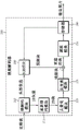
Fig. 1 is a block diagram schematically illustrating a video encoder according to an embodiment of the present invention.
Fig. 2 is a block diagram schematically illustrating a video decoder according to an embodiment of the present invention.
Fig. 3 is a flow chart schematically illustrating an intra prediction method in a video decoder.
Fig. 4 is a diagram illustrating prediction directions in an intra prediction mode.
Fig. 5 is a diagram illustrating an example in which a current block is encoded in an Intra _ DC prediction mode.
Fig. 6 is a diagram illustrating an example in which a prediction direction is vertical in an intra prediction mode according to an embodiment of the present invention.
Fig. 7 is a diagram illustrating an example in which a prediction direction is horizontal in an intra prediction mode according to an embodiment of the present invention.
Fig. 8 is a diagram illustrating an example in which an intra prediction mode is divided depending on a prediction direction.
Fig. 9 is a diagram illustrating an example in which a prediction direction is an upper right direction in an intra prediction mode according to an embodiment of the present invention.
Fig. 10 is a diagram illustrating an example in which a prediction direction is a lower-left direction in an intra prediction mode according to an embodiment of the present invention.
Fig. 11 is a diagram illustrating an example in which a prediction direction is vertical in an intra prediction mode according to another embodiment of the present invention.
Fig. 12 is a diagram illustrating an example in which a prediction direction is horizontal in an intra prediction mode according to another embodiment of the present invention.
Fig. 13 is a diagram schematically illustrating the operation of an encoder in a system according to the invention.
Fig. 14 is a diagram schematically illustrating the operation of a decoder in a system according to the invention.
Detailed Description
The present invention is capable of various embodiments, and specific embodiments thereof will be described in detail with reference to the accompanying drawings. However, the present invention is not limited to the specific embodiments, and may be modified in various forms without departing from the technical scope of the present invention.
The terms used in the following description are only used for describing specific embodiments, but are not intended to limit the technical spirit of the present invention. Singular references include plural references as long as they are clearly read differently.
On the other hand, elements in the drawings described in the present invention are separately drawn for convenience of explaining different specific functions in a video encoder/decoder, and it is not intended that the respective elements be implemented by separate hardware or separate software. For example, two or more of the elements may be combined to form a single element, or one element may be divided into a plurality of elements. Embodiments in which the elements are combined and/or broken down are within the scope of the invention without departing from the concept thereof.
Hereinafter, exemplary embodiments of the present invention will be described in detail with reference to the accompanying drawings. Similar components in the drawings will be referred to by similar reference numerals and will not be described repeatedly.
Fig. 1 is a block diagram schematically illustrating a video encoder according to an embodiment of the present invention. Referring to fig. 1, the video encoder 100 includes a picture decomposition module 105, a prediction module 110, a transform module 115, a quantization module 120, a rearrangement module 125, an entropy coding module 130, a dequantization module 135, an inverse transform module 140, a filtering module 145, and a memory 150.
The picture decomposition module 105 may divide an input image into one or more processing units. Here, the processing unit may be a prediction unit ("PU"), a transform unit ("TU"), or a coding unit ("CU").
The prediction module 110 includes an inter prediction module that performs an inter prediction process, and an intra prediction module that performs an intra prediction process. The prediction module 110 performs a prediction process on the processing units of the picture decomposed by the picture decomposition module 105 to construct a prediction block. Here, the processing unit of a picture may be a CU, a TU, or a PU. The prediction module 110 determines whether inter prediction or intra prediction is to be performed on the corresponding processing unit, and performs a prediction process using the determined prediction method. Here, the processing unit subjected to the prediction processing may be different from the processing unit of the determined prediction method. For example, the prediction method may be determined in units of PUs, and the prediction process may be performed in units of TUs.
In inter prediction, the prediction process is performed based on information on at least one of a previous picture and/or a subsequent picture of a current picture to construct a prediction block. In intra prediction, the prediction process is performed based on pixel information of a current picture to construct a prediction block.
In inter prediction, a reference picture is selected for a current block, and a reference block having the same size as the current block is selected in units of inter-pixel sampling. Subsequently, a prediction block in which the residual value from the current block is minimized and the motion vector magnitude is minimized is constructed. In the inter prediction, a skip mode, a merge mode, an MVP (motion vector prediction) mode, and the like may be used. The prediction block may be constructed in units of pixel samples smaller than integer pixels, such as 1/2 pixel samples and 1/4 pixel samples. Here, the motion vector may also be expressed in units of pixel samples smaller than integer pixels. For example, the luminance component may be represented in 1/4 pixels, and the chrominance component may be represented in 1/8 pixels. Information such as an index of a reference picture selected via inter prediction, a motion vector, and a residual signal is entropy-encoded and transmitted to a decoder.
In the intra prediction, the prediction mode may be determined by a prediction unit, and the prediction process may be performed by the prediction unit or a transform unit. In intra prediction, 33 directional prediction modes and at least two non-directional modes may be supported. Here, the non-directional prediction mode may include a DC prediction mode and a planar mode.
On the other hand, when sampling is used in this specification, this refers to using sampled information, for example, pixel values. For convenience of explanation, the expression "use sampling information" or "use pixel value" may be simply expressed by "use sampling".
The prediction unit may have various sizes/shapes. For example, in the case of inter prediction, the prediction unit may have a size such as 2N × 2N, 2N × N, N × 2N, and N × N. In the case of intra prediction, the prediction unit may have a size such as 2N × N and N × N. Here, a prediction unit having a size of N × N may be set only for a specific case. For example, a prediction unit having an N × N size may be set only for a coding unit having a minimum size, or may be set only for intra prediction. In addition to prediction units having the above-mentioned sizes, prediction units having sizes such as N × mN, mN × N, 2N × mN, and mN × 2N (where m <1) may be additionally defined and used.
The residual block between the constructed prediction block and the original block may be input to the transform module 115. Information such as a prediction mode, a prediction unit, and a motion vector for prediction is entropy-encoded by the entropy encoding module 130 and transmitted to a decoder.
The transform module 115 performs a transform process on the residual block and generates transform coefficients. The processing unit in the transform module 115 may be a transform unit and may have a quad-tree structure. The size of the transform unit may be determined within a range of predetermined maximum and minimum sizes. The transform module 115 may transform the residual block using DCT (discrete cosine transform) and/or DST (discrete sine transform).
The quantization module 120 quantizes the transform coefficient created by the transform module 115 and creates a quantized coefficient. The quantized coefficients created by the quantization module 120 are provided to the rearrangement module 125 and the dequantization module 135.
The rearrangement module 125 may rearrange the quantization coefficients supplied from the quantization module 120. By rearranging the quantized coefficients, it is possible to improve the coding efficiency in the entropy coding module 130. The rearrangement module 125 rearranges the quantization coefficients in the form of two-dimensional blocks into the form of one-dimensional vectors by using a coefficient scanning method. The rearrangement module 125 may improve entropy encoding efficiency in the entropy encoding module 130 by changing the order of coefficient scanning based on random statistics of the quantized coefficients provided from the quantization module 120.
The entropy coding module 130 performs entropy coding processing on the quantized coefficients rearranged by the rearrangement module 125. Here, encoding methods such as an exponential golomb method and a CABAC (context adaptive binary arithmetic coding) method may be used. The entropy encoding module 130 encodes various information such as module type information, prediction mode information, decomposition unit information, prediction unit information, transmission unit information, motion vector information, reference picture information, module interpolation information, and filtering information, which are transmitted from the prediction module 110.
The entropy encoding module 130 may give a predetermined variation to a parameter set or syntax to be transmitted, if necessary.
The dequantization module 135 dequantizes the values quantized by the quantization module 120. The inverse transform module 140 inversely transforms the values dequantized by the dequantization module 135. The residual block reconstructed by the dequantization module 135 and the inverse transform module 140 is added to the prediction block constructed by the prediction module 110 to construct a reconstructed block.
The filtering module 145 applies deblocking filtering, ALF (adaptive loop filtering), SAO (sample adaptive offset), and the like to the reconstructed picture.
The deblocking filtering removes block distortion generated at a boundary between blocks in a reconstructed picture. The ALF performs a filtering process by deblocking filtering based on a result value of comparing the original picture with the reconstructed picture. ALF can be applied only when high efficiency is required. The SAO reconstructs an offset difference between a residual block to which the deblocking filtering is applied and an original picture in units of pixels, and is applied in the form of a band offset, an edge offset, and the like.
On the other hand, the module for reconstruction of inter prediction may not be subjected to the filtering process.
The memory 150 stores reconstructed blocks or pictures. The reconstructed block or picture stored in the memory 150 is provided to the prediction module 110 that performs inter prediction.
Fig. 2 is a block diagram schematically illustrating a video decoder according to an embodiment of the present invention. Referring to fig. 2, the video decoder 200 includes an entropy decoding module 210, a rearranging module 215, a dequantizing module 220, an inverse transform module 225, a prediction module 230, a filtering module 235, and a memory 240.
When a video bitstream is input from an encoder, the input bitstream may be decoded based on an order in which video information is processed by the video encoder.
For example, when the video encoder performs the entropy encoding process using CAVLC, the entropy decoding module 210 performs the entropy decoding process using CABAC corresponding to the entropy decoding process.
The residual signal entropy-decoded by the entropy decoding module 210 is provided to the rearrangement module 215, and information for constructing a prediction block among information entropy-decoded by the entropy decoding module 210 is provided to the prediction module 230.
The rearrangement module 215 rearranges the bitstream entropy-decoded by the entropy decoding module 210 based on a rearrangement method used in the video encoder. The rearranging module 215 is supplied with information on the scanning of coefficients performed by the encoder, and reconstructs and rearranges the coefficients represented in the form of one-dimensional vectors into coefficients in the form of two-dimensional blocks by inversely performing the scanning based on the scanning order in which the scanning was performed by the encoder.
The dequantization module 220 performs dequantization based on the quantization parameter provided from the encoder and the rearranged coefficient value of the block.
The inverse transform module 225 performs an inverse transform of the transform performed by the transform module of the encoder. The inverse transform may be performed based on the transmission unit or the decomposition unit determined by the encoder. The transform module of the encoder may selectively perform DCT and DST according to pieces of information such as a prediction method, the size of the current block, and a prediction direction, and the inverse transform module 225 of the decoder may perform inverse transform based on transform information regarding the transform performed by the transform module of the encoder.
The prediction module 230 constructs a prediction block based on the prediction block structure information provided from the entropy decoding module 210 and previously decoded block and/or picture information provided from the memory 240. The reconstructed block is constructed based on the prediction block constructed by the prediction module 230 and the residual block provided from the inverse transform module 225. For example, when the current block is encoded in the inter prediction mode, inter prediction is performed on the current prediction unit based on information included in at least one of a previous picture and a subsequent picture of the current picture. Here, motion information necessary for inter prediction, such as a motion vector and a reference picture index, may be derived from a skip flag, a merge flag, and the like, provided from an encoder.
The reconstructed block and/or picture may be provided to a filtering module 235. The filtering module 235 performs a deblocking filtering process, an SAO (sample adaptive offset) process, and/or an adaptive loop filtering process on the reconstructed block and/or picture.
The reconstructed picture or block may be stored in the memory 240 for use as a reference picture or reference block and may be provided to an output module (not shown).
On the other hand, the encoder encodes the encoding target block using the most efficient encoding method based on the video information of the encoding target block, and the decoder determines the decoding method based on the encoding method used in the encoder. The encoding method used in the encoder may be derived from a bitstream transmitted by the encoder or based on information of the decoding target block. When the current block is encoded in the intra prediction mode, intra prediction to construct a prediction block is performed based on pixel information of the current picture.
Fig. 3 is a flow chart schematically illustrating an intra prediction method in a video decoder.
The decoder derives a prediction mode of the current block (S310).
The intra prediction mode may have a prediction direction depending on a position of a reference sample used for prediction. The Intra prediction mode having the prediction direction is referred to as a directional Intra prediction mode (Intra _ Angular prediction mode). In contrast, examples of the Intra prediction mode having no prediction direction include an Intra _ Planar prediction mode, an Intra _ DC prediction mode, and an Intra _ Fromlum prediction mode.
Fig. 4 illustrates prediction directions of intra prediction modes, and table 1 shows mode values of the intra prediction modes illustrated in fig. 4.
TABLE 1
| Intra prediction mode | Name of |
| 0 | |
| 1 | Intra_DC |
| 2…34 | Intra_Angular |
| 35 | Intra_FromLima |
In intra prediction, a prediction process is performed on a current block based on a derived prediction mode. The reference samples and the particular prediction method used for the prediction vary depending on the prediction mode. Accordingly, when the current block is encoded in the intra prediction mode, the decoder derives the prediction mode of the current block to perform prediction.
The decoder may check whether a neighboring sample of the current block can be used for the prediction, and may construct a reference sample to be used for the prediction (S320). In intra prediction, the contiguous samples of the current block refer to samples having a length of 2 × nS adjacent to the left boundary and the left lower edge of the current block having a size of nS × nS, and samples having a length of 2 × nS adjacent to the upper boundary and the right upper edge of the current block. However, some contiguous samples of the current block may still not be decoded or may not be available. In this case, the decoder may construct a reference sample for prediction by replacing an unavailable sample with an available sample.
The decoder may perform filtering on the reference samples based on the prediction mode (S330). The decoder may perform a filtering process on the reference samples prior to performing the prediction. Whether the reference sample is to be subjected to the filtering process depends on the prediction mode determination of the current block. Performing filtering adaptively on the reference samples depending on the prediction mode is called MDIS (mode dependent internal smoothing) or simply smoothing filtering.
Table 2 shows an example in which it is determined whether the reference sample is to be subjected to filtering based on the prediction mode.
TABLE 2

When intraFilterType is equal to 1 in table 2, smoothing filtering is performed. For example, when intraPredMode is Intra _ Planar mode and establishes nS 8, smooth filtering may be performed. At this time, smoothing filtering with various filter coefficients may be applied. For example, a smoothing filter with coefficients of [121] may be applied.
The decoder constructs a prediction block for the current block based on the prediction mode and the reference sample (S340). The decoder constructs a prediction block for the current block based on the prediction mode derived in the prediction mode deriving step (S310) and the reference sample obtained in the reference sample filtering step (S330).
In the prediction block construction step (S340), when the current block is encoded in Intra _ DC prediction, left and upper boundary samples of the prediction block may be subjected to 2-tap filtering in order to minimize interruption of the block boundary. Here, the boundary samples refer to samples located in the prediction block and adjacent to the boundary of the prediction block.
Fig. 5 is a diagram illustrating an example in which a current block is encoded in an Intra _ DC prediction mode.
Referring to fig. 5, when the current block 500 is encoded in the Intra _ DC prediction mode, the left boundary sample 522 and the upper boundary sample 521 of the current block 500 may be very similar to the left reference sample 530 and the upper reference sample 510, respectively, and thus, smooth filtering may be applied, as shown in fig. 5. In the figure, a hatched portion 505 represents a filter target region.
In some modes of the directional Intra prediction mode, 2-tap filtering may be applied to the left and upper boundary samples similar to the Intra _ DC prediction mode. Here, the 2-tap filtering is not applied to both the left boundary sample and the upper boundary sample, but is adaptively applied to either the left boundary sample or the upper boundary sample depending on the prediction direction. That is, the 2-tap filtering is applied only to boundary samples adjacent to the reference sample that is not actually used for prediction of the direction.
In particular, in the prediction block construction step (S340), when the current block is encoded in the directional intra prediction mode, the value of the predicted sample may be derived from a reference sample located in the prediction direction. Here, in some modes of the directional intra prediction mode, boundary samples that are not located in a prediction direction among left boundary samples and upper boundary samples of the prediction module may be adjacent to reference samples that are not used for the prediction. That is, the distance to the reference sample not used for the prediction may be much smaller than the distance to the reference sample used for the prediction. Since there is a high possibility that the value of the predicted sample is similar to the reference sample having a small distance, filtering is applied to the reference sample adjacent to the boundary sample that is not located in the prediction direction among the left boundary sample and the upper boundary sample in the present invention in order to improve prediction performance and coding efficiency.
For convenience of explanation, the process of deriving values of predicted samples in the directional intra prediction mode will be described in two steps of deriving values of reference samples located in a prediction direction as values of the predicted samples, and filtering and modifying boundary samples not located in the prediction direction among left and upper boundary samples of the predicted block. The [ x, y ] coordinates in which the coordinate values increase in the lower right direction are set with respect to the prediction block and the upper left sample of the current block. The sizes of the current block and the prediction block are defined as nS. For example, the upper left boundary sample of the prediction block has a position of [0, 0], the left boundary sample has a position of [0, 0.. nS-1], and the upper boundary sample has a position of [0.. nS-1, 0 ].
First, the values of the predicted samples are derived based on reference samples located in the prediction direction.
For example, when the current block is encoded in the vertical prediction mode, the value of the predicted sample is derived as the value of a sample having the same x-coordinate among reference samples adjacent to the upper boundary of the current block. That is, the value predSamples [ x, y ] of the predicted sample is derived from expression 1.
predSamples [ x, y ] ═ p [ x, -1], where x, y ═ o
Here, p [ a, b ] denotes the value of a sample having a [ a, b ] position.
For example, when the current block is encoded in the horizontal prediction mode, the value of the predicted sample is derived as the value of a sample having the same y-coordinate among reference samples adjacent to the left boundary of the current block. That is, the value predSamples [ x, y ] of the predicted sample is derived from expression 2.
Expression 2
predSamples [ x, y ] ═ p [ -1, y ], where x, y ═ o
For example, when the current block is encoded in a directional intra prediction mode in which the prediction direction is the upper right direction, the value of the predicted sample is derived as the value of a reference sample located in the prediction direction among a reference sample adjacent to the upper boundary of the current block and a reference sample located at the upper right edge.
For example, when the current block is encoded in a directional intra prediction mode in which the prediction direction is a lower-left direction, the value of the predicted sample is derived as the value of a reference sample located in the prediction direction among a reference sample adjacent to a left boundary of the current block and a reference sample located at a lower-left edge.
By deriving values of predicted samples based on reference samples located in a prediction direction and then filtering boundary samples not located in the prediction direction among left and upper boundary samples of a prediction block based on neighboring reference samples, it is possible to modify values of the corresponding boundary samples. A method of filtering boundary samples that are not located in a prediction direction among left boundary samples and upper boundary samples of a prediction block using reference samples that are not located in the prediction direction will be described in detail below with reference to fig. 5 to 13.
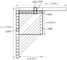
Fig. 6 is a diagram illustrating an example in which the prediction direction of the intra prediction mode according to an embodiment of the present invention is vertical.
Referring to fig. 6, in case of a vertical prediction mode (intra vertical prediction mode), a smoothing filter may be applied to the left boundary samples 620.
As described above, when the current block 600 is encoded in the vertical prediction mode, the value of the predicted sample is derived as the value of the up-reference sample. Here, the reference sample adjacent to the left boundary of the current block 600 is not used for prediction of a direction, but is adjacent to the left boundary of the current block 600. That is, in the left boundary sample 620, the distance to the left reference sample 630 (which is a reference sample not used for prediction) is smaller than the distance to the up-reference sample 610 (which is a reference sample used for prediction). Here, the up-reference sample 610 refers to a sample [ x, -1] adjacent to the upper boundary of the current block and has the same x-coordinate. The left reference sample 630 refers to a sample [ -1, y ] adjacent to the left boundary of the current block, and has the same y-coordinate. Thus, because there is a high likelihood that the values of the left boundary samples 620 are similar to the values of the left reference samples 630, a smoothing filter may be applied to the left boundary samples 620, as shown in fig. 6. The hatched portion 605 in the figure represents the filtering target region.
For example, when applying a smooth filtering with coefficients of [11]/2, the modified value predSamples [ x, y ] of the left boundary sample 620 can be derived from expression 3.
predSamples [ x, y ] (p [ x, -1] + p [ -1, y ])/2, where x ═ 0, y ═ 0
The coefficient of the filter is not limited to [11]/2, but a filter having coefficients such as [13]/4 and [17]/8 may be applied. The coefficients of the filter may be adaptively determined depending on the size of the current block.
On the other hand, the information of the neighboring blocks may be further considered when performing filtering on the left reference samples. For example, depending on the y coordinate value of the left boundary sample 620 relative to the top-left reference sample 640, a modified value of the left boundary sample 620 may be derived as represented by expression 4, taking into account the change in the sample value.
Expression 4
predSamples [ x, y ] ═ p [ x, -1] + (p [ -1, y ] -p [ -1, -1]), where x ═ 0, y ═ 0.. nS-1
When the values of the left boundary samples 620 are derived using the above-mentioned method, the values of the predicted samples may exceed a defined bit depth. Thus, the values of the predicted samples may be limited to a defined bit depth, or weights may be given to the differences therebetween. For example, in the case of predicted samples of the luminance component, the modified value of the left boundary sample 620 may be derived from expression 5.
predSamples[x,y]=Clip1Y(p[x,-1]+((p[-1,y]-p[-1,-1]) /2)), where x ═ 0, y ═ 0.. nS-1)
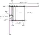
Fig. 7 is a diagram illustrating an example in which a prediction direction of an intra prediction mode according to an embodiment of the present invention is horizontal.
Referring to fig. 7, in case of a horizontal prediction mode (intra horizontal prediction mode), a smoothing filter may be applied to the upper boundary samples 720.
As described above, when the current block 700 is encoded in the vertical prediction mode, the value of the predicted sample is derived as the value of the left reference sample. Here, the reference sample adjacent to the upper boundary of the current block 700 is not used for prediction of a direction, but is sampled adjacent to the upper boundary of the current block 700. That is, in the upper boundary samples 720, the distance to the upper reference sample 710 (which is a reference sample not used for prediction) is smaller than the distance to the left reference sample 730 (which is a reference sample used for prediction). Here, the up-reference sample 710 refers to a sample [ x, -1] adjacent to the upper boundary of the current block and has the same x-coordinate. The left reference sample 730 refers to a sample [ -1, y ] adjacent to the left boundary of the current block and has the same y-coordinate. Accordingly, since there is a high probability that the value of the upper boundary sample 720 is similar to the value of the upper reference sample 710, a smoothing filter may be applied to the upper boundary sample 720, as shown in fig. 7. The hatched portion 705 in the figure represents a filtering target region.
For example, when applying smooth filtering with coefficients of [11]/2, the modified value predSamples [ x, y ] of the upper boundary sample 720 can be derived from expression 6.
Expression 6
predSamples [ x, y ] (p [ -1, y ] + p [ x, -1])/2, where x ═ 0.. nS-1, y ═ 0
The coefficient of the filter is not limited to [11]/2, but a filter having coefficients such as [13]/4 and [17]/8 may be applied. The coefficients of the filter may be adaptively determined depending on the size of the current block.
On the other hand, the information of the neighboring blocks may further consider performing filtering on the upper reference samples. For example, depending on the x-coordinate value of the upper boundary sample 720 relative to the upper left reference sample 740, the modified value of the upper boundary sample 720 may be derived as represented by expression 7, taking into account the change in the sample value.
Expression 7
predSamples [ x, y ] ═ p [ -1, y ] + (p [ x, -1] -p [ -1, -1]), where x ═ 0.. nS-1, y ═ 0
When the values of the upper boundary samples 720 are derived using the above-mentioned method, the values of the predicted samples may exceed a defined bit depth. Thus, the values of the predicted samples may be limited to a defined bit depth, or weights may be given to the differences therebetween. For example, in the case of predicted samples of the luminance component, the modified value of the upper boundary sample 720 may be derived by expression 8.
Expression 8
predSamples[x,y]=Clip1γ(p[-1,y]+((p[x,-1]-p[-1,-1]) /2)), where x ═ 0.. nS-1, y ═ 0)
On the other hand, the method of applying the smoothing filter to the left boundary sample or the upper boundary sample based on the prediction mode of the current block may be applied to other directional intra prediction modes in addition to the vertical prediction mode and/or the horizontal prediction mode.
For example, the directional intra prediction modes may be divided depending on the prediction direction, and the filtering may be adaptively performed depending on the group to which the corresponding mode belongs.
Fig. 8 is a diagram illustrating an example in which an intra prediction mode is divided depending on a prediction direction.
When the prediction direction of the intra prediction mode is the upper right direction 810, the smoothing filtering may be applied to the left boundary samples, similar to the vertical prediction mode. When the prediction direction of the intra prediction mode is the lower left direction 820, the smoothing filtering may be applied to the upper boundary samples, similar to the horizontal prediction mode.
Fig. 9 is a diagram illustrating an example in which a prediction direction of an intra prediction mode is an upper right direction according to an embodiment of the present invention.
As described above, when the current block 900 is encoded in the directional intra prediction mode in which the prediction direction thereof is the upper-right direction, the value of the predicted sample is derived as the value of the reference sample 910 located in the prediction direction among the reference sample located adjacent to the right-side boundary of the current block and the reference sample 910 located at the upper-right edge. Here, the reference sample adjacent to the left boundary of the current block 900 is not used, but is adjacent to the left boundary sample. That is, the left boundary sample 920 has a distance to the left reference sample 930 that is less than the distance to the reference sample 910 located in the prediction direction. Here, the left reference sample 930 refers to a sample [ -1, y ] adjacent to the left boundary of the current block and has the same y coordinate. Accordingly, because there is a high likelihood that the value of the left boundary sample 920 is similar to the value of the adjacent left reference sample 930, a smoothing filter may be applied to the left boundary sample 920, as shown in fig. 9. A hatched portion 905 in the figure represents a filtering target region.
Fig. 10 is a diagram illustrating an example in which a prediction direction of an intra prediction mode is a lower-left direction according to an embodiment of the present invention.
As described above, when the current block 1000 is encoded in the directional intra prediction mode in which the prediction direction thereof is the lower-left direction, the value of the predicted sample is derived as the value of the reference sample 1030 located in the prediction direction among the reference sample located adjacent to the left boundary of the current block and the reference sample located at the lower-left edge. Here, the reference sample adjacent to the upper boundary of the current block 1000 is not used, but is adjacent to the upper boundary sample. That is, the upper boundary sample 1020 has a distance to the upper reference sample 1010 that is less than a distance to the reference sample 1030 located in the prediction direction. Here, the up-reference sample 1010 refers to a sample [ x, -1] adjacent to the upper boundary of the current block and has the same x-coordinate. Thus, because there is a high likelihood that the value of the upper boundary sample 1020 is similar to the value of the adjacent upper reference sample 1030, a smoothing filter may be applied to the upper boundary sample 1020, as shown in fig. 10. A hatched portion 1005 in the figure indicates a filtering target region.
On the other hand, as described above, for the purpose of convenience of explanation, the process of deriving the values of the predicted samples has been described in two steps of the step of deriving the values of the reference samples located in the prediction direction as the values of the predicted samples, and the step of filtering and modifying the boundary samples not located in the prediction direction among the left boundary samples and the upper boundary samples of the prediction block, but the process of deriving the values of the predicted samples may not be divided into a plurality of steps, but may be performed in a single step. For example, in deriving values of boundary samples that are not located in a prediction direction among left and upper boundary samples of a prediction block, the step of filtering the boundary samples may not be performed as a separate step, but may be performed as a unified step having a step of deriving values of predicted samples as values of reference samples located in the prediction direction.
For example, in the example illustrated in fig. 6, the value of the left boundary sample 620 may be derived based on the up-reference sample 610 and the reference sample 630 adjacent to the left boundary sample as represented by expressions 3 through 5.
For example, in the example illustrated in fig. 7, the value of the upper boundary sample 720 may be derived based on the left reference sample 730 and the reference sample 710 adjacent to the upper boundary sample as represented by expressions 6 to 8.
For example, in the example illustrated in fig. 9, the value of the left boundary sample 920 may be derived based on the reference sample 910 located in the prediction direction and the reference sample 930 adjacent to the left boundary sample.
For example, in the example illustrated in fig. 10, the value of the upper boundary sample 1020 may be derived based on the reference sample 1030 located in the prediction direction and the reference sample 1010 adjacent to the upper boundary sample.
On the other hand, since smooth filtering is not performed on the predicted samples except for boundary samples that are not located in the prediction direction among the left boundary samples and the upper boundary samples of the prediction block, the values of the predicted samples are derived as the values of the reference samples in the prediction direction.
For example, when the current block is encoded in the vertical prediction mode, the values of the predicted samples are derived as represented by expression 9 except for the left boundary sample.
Expression 9
predSamples [ x, y ] ═ p [ x, -1], where x ═ 1.. nS-1, y ═ 0.. nS-1
For example, when the current block is encoded in the horizontal prediction mode, the values of the predicted samples are derived as represented by expression 10, except for the upper boundary samples.
predSamples [ x, y ] ═ p [ -1, y ], where x ═ o
On the other hand, the method of applying the smoothing filter to the left boundary sample or the upper boundary sample based on the prediction mode of the current block may not be applied to all the prediction samples of the boundary samples, but may be applied to only some of them.
When the distance to the reference sample for prediction of the direction is small, the error of the predicted sample may not be large. In this case, the smoothing filtering is applied rather inaccurately, that is, without taking into account other sampling information. Thus, it may be determined whether filtering is to be performed on neighboring reference samples depending on the location of the boundary sample in the block.
For example, the smoothing filtering may be applied only to some of the left boundary samples in the vertical prediction mode, or the smoothing filtering may be applied only to some of the upper boundary samples in the horizontal prediction mode.
Fig. 11 is a diagram illustrating an example in which a prediction direction of an intra prediction mode is vertical according to an embodiment of the present invention. Referring to fig. 11, the smoothing filter may be applied to only some of the left boundary samples. That is, the greater the distance to the reference sample used for prediction becomes, the lower the prediction accuracy becomes. Therefore, the smoothing filter may be applied only to the samples in the region with low precision.
For example, the smoothing filtering may be applied only to the left boundary sample 1120 spaced apart from the upper reference sample 1110 among the left boundary samples with respect to half the height of the current block 1100. A hatched portion 1105 in the figure represents a filtering target region.
Even when the prediction mode of the current block is the horizontal prediction mode, it may determine whether filtering is to be performed on neighboring reference samples depending on the position of the upper boundary sample in the block.
Fig. 12 is a diagram illustrating an example in which a prediction direction of an intra prediction mode is horizontal according to another embodiment of the present invention. Referring to fig. 12, the smoothing filter may be applied to only some upper boundary samples.
For example, the smoothing filtering may be applied only to the upper boundary samples 1220 spaced apart from the left reference sample 1230 among the upper boundary samples with respect to a half width of the current block 1200. A hatched portion 1205 in the figure represents a filtering target region.
On the other hand, the region to which the smoothing filter is applied is not limited to the half height or width of the current block. That is, the region may be set to have a size of 1/4 or 3/4 thereof, or may be adaptively determined based on a distance to a sample used for the prediction depending on an intra prediction mode. In this case, the region to which the smoothing filter is applied may be defined in a lookup table to reduce the computational load of the encoder or decoder.
On the other hand, the technical spirit of the present invention may be applied to both the luminance component and the chrominance component, but may be applied only to the luminance component and may not be applied to the chrominance component. When the technical spirit of the present invention is applied only to the luminance component, the values of the predicted samples of the chrominance component are derived using the same method as the conventional intra prediction mode.
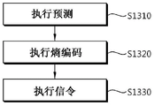
Fig. 13 is a diagram schematically illustrating the operation of an encoder in a system according to the invention.
The encoder performs a prediction process on the current block (S1310). The encoder constructs a prediction block for the current block based on the prediction mode of the current block. Here, the neighboring samples of the current block may be used as reference samples to derive values of the predicted samples.
When the prediction mode of the current block is the directional intra prediction mode, the encoder may derive a value of a boundary sample that is not located in the prediction direction of the directional intra prediction mode among left and upper boundary samples of the prediction block based on a reference sample located in the prediction direction and a reference sample adjacent to the boundary sample. Here, the boundary samples refer to samples located in the prediction block and adjacent to the boundary of the prediction block.
For example, when the directional intra prediction mode is the vertical prediction mode, the encoder may derive the value of the left boundary sample based on the upper reference sample of the left boundary sample and the reference sample adjacent to the left boundary sample. Here, the upper reference sample refers to a sample adjacent to the upper boundary of the current block and having the same x-coordinate.
For example, when the directional intra prediction mode is the vertical prediction mode, the encoder may derive a value of the left boundary sample based on an up-reference sample of the left boundary sample, a reference sample adjacent to the left boundary sample, and a reference sample adjacent to a left upper edge of the current block.
For example, when the directional intra prediction mode is the horizontal prediction mode, the encoder may derive the value of the upper boundary sample based on the left reference sample of the upper boundary sample and the reference sample adjacent to the upper boundary sample. Here, the left reference sample refers to a sample adjacent to the left boundary of the current block and having the same y-coordinate.
For example, when the directional intra prediction mode is the horizontal prediction mode, the encoder may derive a value of the upper boundary sample based on the left reference sample of the upper boundary sample, the reference sample adjacent to the upper boundary sample, and the reference sample adjacent to the upper left edge of the current block.
For example, when the prediction direction of the prediction mode is the upper right direction, the encoder may derive the value of the left boundary sample based on a reference sample located in the prediction direction and a reference sample adjacent to the left boundary sample.
For example, when the prediction direction of the prediction mode is a lower-left direction, the encoder may derive the value of the upper boundary sample based on a reference sample located in the prediction direction and a reference sample adjacent to the upper boundary sample.
On the other hand, the encoder may derive a value of a predicted sample other than a boundary sample that is not located in a prediction direction of the directional intra prediction mode among left and upper boundary samples of the prediction block as a value of a reference value located in the prediction direction.
For example, when the directional intra prediction mode is the vertical prediction mode, the encoder may derive the value of the predicted sample as the value of the up-reference sample of the predicted sample.
For example, when the directional intra prediction mode is the horizontal prediction mode, the encoder may derive the value of the predicted sample as the value of the left reference sample of the predicted sample.
The encoder entropy-encodes information on the prediction block constructed in the prediction step S1310 (S1320). As described above, encoding methods such as the exponent golomb and CABAC may be used for entropy encoding, and codewords may be assigned in consideration of the occurrence frequency of prediction modes or prediction types.
The encoder indicates the information encoded in the entropy encoding step S1320 (S1330). For example, the encoder may indicate prediction mode information and a residual signal between the prediction block and the original block. When smoothing filtering is applied to perform the intra prediction process, information on the smoothing filter coefficients may be illustrated.
Fig. 14 is a schematic diagram schematically illustrating the operation of a decoder in a system according to the invention.
The decoder receives information from the encoder (S1410). The information received from the encoder may be provided with a bitstream having the information loaded thereon.
The decoder entropy decodes the information received in the information receiving step S1410 (S1420). The decoder may obtain information for prediction of the current block, such as a prediction method (inter prediction/intra prediction), a motion vector (inter prediction), a prediction mode (intra prediction), and a residual signal of the current block in the entropy decoding step S1420.
The decoder performs a prediction process on the current block based on the information obtained in the entropy decoding step S1420 (S1430). The decoder constructs a prediction block for the current block based on the prediction mode for the current block. Here, the neighboring samples of the current block may be used as reference samples in order to derive values of the predicted samples.
The prediction method performed in the decoder is the same as or similar to the prediction method performed in the encoder.
That is, when the prediction mode of the current block is the directional intra prediction mode, the decoder may derive values of boundary samples that are not located in the prediction direction of the directional intra prediction mode among left and upper boundary samples of the prediction block, based on reference samples located in the prediction direction and reference samples adjacent to the corresponding boundary samples.
For example, the directional intra prediction mode is a vertical prediction mode, and the decoder may derive a value for the left boundary sample based on the up-reference sample for the left boundary sample and the reference sample adjacent to the left boundary sample.
For example, the directional intra prediction mode is a vertical prediction mode, and the decoder may derive a value of the left boundary sample based on the up-reference sample of the left boundary sample, the reference sample adjacent to the left boundary sample, and the reference sample adjacent to the lower left edge of the current block.
For example, the directional intra prediction mode is a horizontal prediction mode, and the decoder may derive a value of an upper boundary sample based on a left reference sample of the upper boundary sample and a reference sample adjacent to the upper boundary sample.
For example, the directional intra prediction mode is a horizontal prediction mode, and the decoder may derive a value of the upper boundary sample based on the left reference sample of the upper boundary sample, the reference sample adjacent to the upper boundary sample, and the reference sample adjacent to the upper left edge of the current block.
For example, when the prediction direction of the prediction mode is the upper right direction, the decoder may derive the value of the left boundary sample based on the reference sample located in the prediction direction and the reference sample adjacent to the left boundary sample.
For example, when the prediction direction of the prediction mode is a lower-left direction, the encoder may derive a value of the upper boundary sample based on a reference sample located in the prediction direction and a reference sample adjacent to the upper boundary sample.
The decoder may derive a value of a predicted sample other than a boundary sample that is not located in a prediction direction of the directional intra prediction mode among left and upper boundary samples of the prediction block as a value of a reference sample located in the prediction direction.
For example, when the directional intra prediction mode is the vertical prediction mode, the decoder may derive the value of the predicted sample as the value of the up-reference sample of the predicted sample.
For example, when the directional intra prediction mode is the horizontal prediction mode, the decoder may derive the value of the predicted sample as the value of the left reference sample of the predicted sample.
The decoder reconstructs a picture based on the prediction block constructed in the prediction step S1430 (S1440).
Although the method in the above-mentioned exemplary system has been described based on a flowchart including a series of steps or blocks, the present invention is not limited to the order of the steps, and a certain step may be performed in a step or an order other than the above or simultaneously as described above. The above-mentioned embodiments may include various examples. Accordingly, the present invention is intended to embrace all such alternatives, modifications and variances which fall within the scope of the appended claims.
When an element is referred to as being "connected" or "coupled" to another element as above, it is understood that another element may be interposed therebetween, and that the element may be directly connected or coupled to the other element. Conversely, when it is stated that an element is "directly connected to" or "directly coupled to" another element, it is understood that the other element is not interposed therebetween.
Claims (9)
1. A method of intra prediction performed by a decoding device, the method comprising:
deriving an intra prediction mode for the current block;
deriving neighboring reference samples for the current block; and
generating a prediction sample for the current block based on the intra prediction mode and the neighboring reference samples;
wherein the intra-prediction mode is a vertical prediction mode,
wherein the step of generating prediction samples comprises: deriving a prediction sample based on a first neighboring reference sample located in an upper side of an upper boundary of the current block, and performing filtering on the prediction sample based on a second neighboring reference sample located in a left side of the left boundary of the current block when the prediction sample is adjacent to the left boundary of the current block,
wherein the first neighboring reference sample borders an upper boundary of the current block, an
Wherein the second neighboring reference sample borders a left boundary of the current block.
2. The method of claim 1, wherein the first neighboring reference sample has the same x-coordinate as the prediction sample to be filtered.
3. The method of claim 1, wherein the second neighboring reference sample used for filtering the prediction sample has the same y-coordinate as the prediction sample to be filtered.
4. The method of claim 1, wherein the filtering of the prediction sample is further performed based on a third neighboring reference sample located in an upper left side of the current block.
5. The method of claim 4, wherein the filter coefficients applied to the prediction sample and the filter coefficients of the second neighboring reference sample and the third neighboring reference sample located in the upper left side of the current block are the same.
6. A method of intra prediction performed by an encoding device, the method comprising:
deriving an intra prediction mode for the current block;
deriving neighboring reference samples for the current block; and
generating a prediction sample for the current block based on the intra prediction mode and the neighboring reference samples;
wherein the intra-prediction mode is a vertical prediction mode,
wherein the step of generating prediction samples comprises: deriving a prediction sample based on a first neighboring reference sample located in an upper side of an upper boundary of the current block, and performing filtering on the prediction sample based on a second neighboring reference sample located in a left side of the left boundary of the current block when the prediction sample is adjacent to the left boundary of the current block,
wherein the first neighboring reference sample borders an upper boundary of the current block, an
Wherein the second neighboring reference sample borders a left boundary of the current block.
7. The method of claim 6, wherein the first neighboring reference sample has the same x-coordinate as the prediction sample to be filtered.
8. The method of claim 6, wherein the second neighboring reference sample used for filtering the prediction sample has the same y-coordinate as the prediction sample to be filtered.
9. A computer readable storage medium for storing encoded information, the encoded information comprising a decoder executable program that when executed causes the decoder executable program to perform the steps of:
deriving an intra prediction mode for the current block;
deriving neighboring reference samples for the current block; and
generating a prediction sample for the current block based on the intra prediction mode and the neighboring reference samples;
wherein the intra-prediction mode is a vertical prediction mode,
wherein the step of generating prediction samples comprises: deriving a prediction sample based on a first neighboring reference sample located in an upper side of an upper boundary of the current block, and performing filtering on the prediction sample based on a second neighboring reference sample located in a left side of the left boundary of the current block when the prediction sample is adjacent to the left boundary of the current block,
wherein the first neighboring reference sample borders an upper boundary of the current block, an
Wherein the second neighboring reference sample borders a left boundary of the current block.
Applications Claiming Priority (3)
| Application Number | Priority Date | Filing Date | Title |
|---|---|---|---|
| US201161478912P | 2011-04-25 | 2011-04-25 | |
| US61/478,912 | 2011-04-25 | ||
| CN201280030010.9A CN103621079B (en) | 2011-04-25 | 2012-04-20 | Intra-prediction method, and encoder and decoder using same |
Related Parent Applications (1)
| Application Number | Title | Priority Date | Filing Date |
|---|---|---|---|
| CN201280030010.9A Division CN103621079B (en) | 2011-04-25 | 2012-04-20 | Intra-prediction method, and encoder and decoder using same |
Publications (2)
| Publication Number | Publication Date |
|---|---|
| CN107071411A CN107071411A (en) | 2017-08-18 |
| CN107071411B true CN107071411B (en) | 2020-08-28 |
Family
ID=47072876
Family Applications (5)
| Application Number | Title | Priority Date | Filing Date |
|---|---|---|---|
| CN201611127179.2A Active CN107071413B (en) | 2011-04-25 | 2012-04-20 | Encoding apparatus and decoding apparatus performing intra prediction |
| CN201280030010.9A Active CN103621079B (en) | 2011-04-25 | 2012-04-20 | Intra-prediction method, and encoder and decoder using same |
| CN201611127121.8A Active CN107071412B (en) | 2011-04-25 | 2012-04-20 | Intra prediction method performed by encoding apparatus and decoding apparatus |
| CN201611127070.9A Active CN107071411B (en) | 2011-04-25 | 2012-04-20 | Intra-frame prediction method executed by decoding device and encoding device |
| CN201611127178.8A Active CN106851270B (en) | 2011-04-25 | 2012-04-20 | Encoding apparatus and decoding apparatus performing intra prediction |
Family Applications Before (3)
| Application Number | Title | Priority Date | Filing Date |
|---|---|---|---|
| CN201611127179.2A Active CN107071413B (en) | 2011-04-25 | 2012-04-20 | Encoding apparatus and decoding apparatus performing intra prediction |
| CN201280030010.9A Active CN103621079B (en) | 2011-04-25 | 2012-04-20 | Intra-prediction method, and encoder and decoder using same |
| CN201611127121.8A Active CN107071412B (en) | 2011-04-25 | 2012-04-20 | Intra prediction method performed by encoding apparatus and decoding apparatus |
Family Applications After (1)
| Application Number | Title | Priority Date | Filing Date |
|---|---|---|---|
| CN201611127178.8A Active CN106851270B (en) | 2011-04-25 | 2012-04-20 | Encoding apparatus and decoding apparatus performing intra prediction |
Country Status (21)
| Country | Link |
|---|---|
| US (4) | US10368090B2 (en) |
| EP (4) | EP2704435B1 (en) |
| JP (6) | JP5869666B2 (en) |
| KR (8) | KR102164571B1 (en) |
| CN (5) | CN107071413B (en) |
| AU (7) | AU2012249024B2 (en) |
| CA (5) | CA3222766A1 (en) |
| DE (1) | DE112012001609B9 (en) |
| DK (1) | DK2704435T3 (en) |
| ES (2) | ES2848835T3 (en) |
| FI (1) | FI3783889T3 (en) |
| GB (1) | GB2505345B (en) |
| HR (1) | HRP20230996T1 (en) |
| HU (2) | HUE044405T2 (en) |
| MX (4) | MX347329B (en) |
| PL (3) | PL2704435T3 (en) |
| PT (2) | PT2704435T (en) |
| RU (6) | RU2627110C2 (en) |
| SI (1) | SI3783889T1 (en) |
| TR (1) | TR201905119T4 (en) |
| WO (1) | WO2012148138A2 (en) |
Families Citing this family (48)
| Publication number | Priority date | Publication date | Assignee | Title |
|---|---|---|---|---|
| CN107197257B (en) * | 2010-12-08 | 2020-09-08 | Lg 电子株式会社 | Intra prediction method performed by encoding apparatus and decoding apparatus |
| HUE044405T2 (en) | 2011-04-25 | 2019-10-28 | Lg Electronics Inc | Intra-prediction method, and encoder and decoder using same |
| KR20120140181A (en) | 2011-06-20 | 2012-12-28 | 한국전자통신연구원 | Method and apparatus for encoding and decoding using filtering for prediction block boundary |
| KR101956284B1 (en) * | 2011-06-30 | 2019-03-08 | 엘지전자 주식회사 | Interpolation Method And Prediction method thereof |
| CN110868588B (en) | 2012-01-18 | 2023-09-15 | 韩国电子通信研究院 | Video decoding device, video encoding device, and computer-readable recording medium |
| JP2014131162A (en) * | 2012-12-28 | 2014-07-10 | Nippon Telegr & Teleph Corp <Ntt> | Intra-prediction encoding method, intra-prediction decoding method, intra-prediction encoding device, intra-prediction decoding device, program therefor, and program recorded recording medium |
| EP2984839B1 (en) * | 2013-04-08 | 2020-05-27 | GE Video Compression, LLC | Coding concept allowing efficient multi-view/layer coding |
| WO2015009092A1 (en) * | 2013-07-18 | 2015-01-22 | 엘지전자 주식회사 | Method and apparatus for processing video signal |
| US10129542B2 (en) * | 2013-10-17 | 2018-11-13 | Futurewei Technologies, Inc. | Reference pixel selection and filtering for intra coding of depth map |
| EP2961168A1 (en) * | 2014-06-27 | 2015-12-30 | Thomson Licensing | Method and apparatus for predicting image samples for encoding or decoding |
| AU2014216056A1 (en) * | 2014-08-25 | 2016-03-10 | Canon Kabushiki Kaisha | Method, apparatus and system for predicting a block of video samples |
| US11463689B2 (en) * | 2015-06-18 | 2022-10-04 | Qualcomm Incorporated | Intra prediction and intra mode coding |
| KR102160667B1 (en) | 2015-09-10 | 2020-09-28 | 엘지전자 주식회사 | Intra prediction method and apparatus in video coding system |
| US10425648B2 (en) * | 2015-09-29 | 2019-09-24 | Qualcomm Incorporated | Video intra-prediction using position-dependent prediction combination for video coding |
| EP3376764A4 (en) * | 2015-11-12 | 2019-12-04 | LG Electronics Inc. | Method and apparatus for coefficient induced intra prediction in image coding system |
| US10432947B2 (en) | 2015-11-24 | 2019-10-01 | Samsung Electronics Co., Ltd. | Method and apparatus for decoding video, and method and apparatus for coding video |
| WO2017090957A1 (en) * | 2015-11-24 | 2017-06-01 | 삼성전자 주식회사 | Video encoding method and apparatus, and video decoding method and apparatus |
| KR102345475B1 (en) * | 2016-01-05 | 2022-01-03 | 한국전자통신연구원 | Method and apparatus for prediction of residual signal |
| WO2017142301A1 (en) | 2016-02-16 | 2017-08-24 | 삼성전자 주식회사 | Method and apparatus for encoding/decoding image |
| KR102609632B1 (en) * | 2016-02-25 | 2023-12-01 | 주식회사 케이티 | Methdo and apparatus for processing a video signal |
| KR102346713B1 (en) * | 2016-04-12 | 2022-01-03 | 세종대학교산학협력단 | Method and apparatus for processing a video signal based on intra prediction |
| JP2019519972A (en) * | 2016-05-05 | 2019-07-11 | ヴィド スケール インコーポレイテッド | Control point based intra direction representation for intra coding |
| WO2017209328A1 (en) * | 2016-06-03 | 2017-12-07 | 엘지전자 주식회사 | Intra-prediction method and apparatus in image coding system |
| CN113873240A (en) * | 2016-06-24 | 2021-12-31 | 株式会社Kt | Method and apparatus for processing video signal |
| PL3972256T3 (en) * | 2016-06-24 | 2024-04-08 | Kt Corporation | Adaptive reference sample filtering for intra prediction using distant pixel lines |
| ES2737845B2 (en) * | 2016-07-05 | 2021-05-19 | Kt Corp | METHOD AND APPARATUS TO PROCESS VIDEO SIGNAL |
| KR102447450B1 (en) | 2016-09-05 | 2022-09-26 | 엘지전자 주식회사 | Video encoding/decoding method and apparatus therefor |
| CN116366838A (en) | 2016-09-20 | 2023-06-30 | 株式会社Kt | Method for decoding and encoding image and transmission method |
| WO2018062880A1 (en) * | 2016-09-30 | 2018-04-05 | 엘지전자(주) | Image processing method and apparatus therefor |
| WO2018174371A1 (en) * | 2017-03-21 | 2018-09-27 | 엘지전자 주식회사 | Image decoding method and device according to intra prediction in image coding system |
| US10728548B2 (en) * | 2017-04-04 | 2020-07-28 | Futurewei Technologies, Inc. | Processing reference samples used for intra-prediction of a picture block |
| HUE060091T2 (en) | 2017-05-31 | 2023-01-28 | Lg Electronics Inc | Method and device for performing image decoding on basis of intra prediction in image coding system |
| US10764587B2 (en) * | 2017-06-30 | 2020-09-01 | Qualcomm Incorporated | Intra prediction in video coding |
| US11831910B2 (en) | 2017-08-21 | 2023-11-28 | Electronics And Telecommunications Research Institute | Method and apparatus for encoding/decoding video, and recording medium storing bit stream |
| GB2567863A (en) * | 2017-10-27 | 2019-05-01 | Sony Corp | Image data encoding and decoding |
| US11445173B2 (en) * | 2017-11-13 | 2022-09-13 | Mediatek Singapore Pte. Ltd. | Method and apparatus for Intra prediction fusion in image and video coding |
| EP3496401A1 (en) * | 2017-12-05 | 2019-06-12 | Thomson Licensing | Method and apparatus for video encoding and decoding based on block shape |
| CN116366845A (en) | 2018-03-09 | 2023-06-30 | 韩国电子通信研究院 | Image encoding/decoding method and apparatus using sample filtering |
| US11483564B2 (en) | 2018-03-19 | 2022-10-25 | Kt Corporation | Method and apparatus for video signal processing determining reference sample lines for a prediction target sample |
| WO2019245342A1 (en) * | 2018-06-21 | 2019-12-26 | 주식회사 케이티 | Video signal processing method and device |
| CN110650349B (en) | 2018-06-26 | 2024-02-13 | 中兴通讯股份有限公司 | Image encoding method, decoding method, encoder, decoder and storage medium |
| CN110876057B (en) * | 2018-08-29 | 2023-04-18 | 华为技术有限公司 | Inter-frame prediction method and device |
| US20220239919A1 (en) * | 2019-06-14 | 2022-07-28 | Telefonaktiebolaget Lm Ericsson (Publ) | Simplified Downsampling for Matrix Based Intra Prediction |
| EP3984228A4 (en) * | 2019-06-14 | 2023-03-29 | Telefonaktiebolaget Lm Ericsson (Publ) | Sample value clipping on mip reduced prediction |
| JP2022536967A (en) * | 2019-06-21 | 2022-08-22 | ヴィド スケール インコーポレイテッド | Accuracy Refinement for Motion Compensation by Optical Flow |
| EP3994881A4 (en) * | 2019-07-05 | 2022-10-19 | Beijing Dajia Internet Information Technology Co., Ltd. | Motion compensation using combined inter and intra prediction |
| CN110944211B (en) * | 2019-11-15 | 2022-07-08 | 腾讯科技(深圳)有限公司 | Interpolation filtering method, device, medium and electronic device for intra-frame prediction |
| CN117499626A (en) * | 2020-03-26 | 2024-02-02 | 阿里巴巴(中国)有限公司 | Method and apparatus for encoding or decoding video |
Family Cites Families (45)
| Publication number | Priority date | Publication date | Assignee | Title |
|---|---|---|---|---|
| JPS60123348A (en) | 1983-11-25 | 1985-07-02 | ナショナル住宅産業株式会社 | Container device |
| JPH06258980A (en) | 1993-03-02 | 1994-09-16 | Ricoh Co Ltd | Electrophotographic device with color vanishing function |
| DE10158658A1 (en) | 2001-11-30 | 2003-06-12 | Bosch Gmbh Robert | Method for directional prediction of an image block |
| KR100454501B1 (en) | 2001-12-26 | 2004-10-28 | 브이케이 주식회사 | Apparatus for prediction to code or decode image signal and method therefor |
| JP4015934B2 (en) | 2002-04-18 | 2007-11-28 | 株式会社東芝 | Video coding method and apparatus |
| MXPA05007449A (en) | 2003-01-10 | 2005-09-12 | Thomson Licensing Sa | Defining interpolation filters for error concealment in a coded image. |
| CN1589028B (en) * | 2004-07-29 | 2010-05-05 | 展讯通信(上海)有限公司 | Predicting device and method based on pixel flowing frame |
| GB0422439D0 (en) | 2004-10-08 | 2004-11-10 | European Molecular Biology Lab Embl | Inhibitors of infection |
| US20090207919A1 (en) * | 2005-07-21 | 2009-08-20 | Peng Yin | Method and Apparatus for Weighted Prediction for Scalable Video Coding |
| KR100678958B1 (en) * | 2005-07-29 | 2007-02-06 | 삼성전자주식회사 | Deblocking filtering method considering intra BL mode, and video encoder/decoder based on multi-layer using the method |
| US8036274B2 (en) | 2005-08-12 | 2011-10-11 | Microsoft Corporation | SIMD lapped transform-based digital media encoding/decoding |
| KR100825743B1 (en) | 2005-11-15 | 2008-04-29 | 한국전자통신연구원 | A method of scalable video coding for varying spatial scalability of bitstream in real time and a codec using the same |
| KR100750145B1 (en) | 2005-12-12 | 2007-08-21 | 삼성전자주식회사 | Method and apparatus for intra prediction of image |
| KR100739790B1 (en) | 2006-02-02 | 2007-07-13 | 삼성전자주식회사 | Method and apparatus for deciding intra prediction mode |
| EP1842846A1 (en) * | 2006-04-07 | 2007-10-10 | Santhera Pharmaceuticals (Schweiz) AG | Phenylpiperidine derivatives as melanocortin-4 receptor modulators |
| KR20110086159A (en) * | 2006-10-10 | 2011-07-27 | 니폰덴신뎅와 가부시키가이샤 | Intra prediction encoding control method and device, its program, and storage medium containing program |
| KR101365570B1 (en) | 2007-01-18 | 2014-02-21 | 삼성전자주식회사 | Method and apparatus for encoding and decoding based on intra prediction |
| CN101383970A (en) | 2007-09-06 | 2009-03-11 | 北京中电华大电子设计有限责任公司 | Intra-frame predictor implementing method based on AVS parallel flow |
| JP2009094828A (en) | 2007-10-10 | 2009-04-30 | Hitachi Ltd | Device and method for encoding image, and device and method for decoding image |
| JP2009111691A (en) * | 2007-10-30 | 2009-05-21 | Hitachi Ltd | Image-encoding device and encoding method, and image-decoding device and decoding method |
| EP2081386A1 (en) * | 2008-01-18 | 2009-07-22 | Panasonic Corporation | High precision edge prediction for intracoding |
| KR20090095316A (en) | 2008-03-05 | 2009-09-09 | 삼성전자주식회사 | Method and apparatus for image intra prediction |
| JP5413923B2 (en) * | 2008-04-11 | 2014-02-12 | トムソン ライセンシング | Deblocking filtering for displacement intra prediction and template matching |
| KR100949917B1 (en) * | 2008-05-28 | 2010-03-30 | 한국산업기술대학교산학협력단 | Fast Encoding Method and System Via Adaptive Intra Prediction |
| CN101330617B (en) | 2008-07-31 | 2010-11-17 | 上海交通大学 | Hardware implementing method and apparatus for anticipater within multi-standard frame based on mode mapping |
| KR101590500B1 (en) * | 2008-10-23 | 2016-02-01 | 에스케이텔레콤 주식회사 | / Video encoding/decoding apparatus Deblocking filter and deblocing filtering method based intra prediction direction and Recording Medium therefor |
| US8189666B2 (en) | 2009-02-02 | 2012-05-29 | Microsoft Corporation | Local picture identifier and computation of co-located information |
| JP5303659B2 (en) | 2009-02-13 | 2013-10-02 | リサーチ イン モーション リミテッド | In-loop deblocking of intra-coded images or frames |
| US20100246675A1 (en) | 2009-03-30 | 2010-09-30 | Sony Corporation | Method and apparatus for intra-prediction in a video encoder |
| KR101379185B1 (en) | 2009-04-14 | 2014-03-31 | 에스케이 텔레콤주식회사 | Prediction Mode Selection Method and Apparatus and Video Enoding/Decoding Method and Apparatus Using Same |
| KR20110008653A (en) | 2009-07-20 | 2011-01-27 | 삼성전자주식회사 | Method and apparatus for predicting motion vector and method and apparatus of encoding/decoding a picture using the same |
| US8199459B2 (en) * | 2009-07-30 | 2012-06-12 | Medtronic, Inc. | Energy device with a first and second separator material |
| KR101452860B1 (en) | 2009-08-17 | 2014-10-23 | 삼성전자주식회사 | Method and apparatus for image encoding, and method and apparatus for image decoding |
| CN101827270B (en) | 2009-12-16 | 2011-12-14 | 香港应用科技研究院有限公司 | Method for acquiring pixel prediction value in intraframe prediction |
| US20120300849A1 (en) * | 2010-01-12 | 2012-11-29 | Yukinobu Yasugi | Encoder apparatus, decoder apparatus, and data structure |
| KR20110113561A (en) * | 2010-04-09 | 2011-10-17 | 한국전자통신연구원 | Method and apparatus for intra prediction encoding and decoding using adaptive filter |
| WO2011136896A1 (en) * | 2010-04-27 | 2011-11-03 | Sony Corporation | Boundary adaptive intra prediction for improving subjective video quality |
| KR101772459B1 (en) * | 2010-05-17 | 2017-08-30 | 엘지전자 주식회사 | New intra prediction modes |
| KR20120012385A (en) | 2010-07-31 | 2012-02-09 | 오수미 | Intra prediction coding apparatus |
| JP5982612B2 (en) | 2010-08-17 | 2016-08-31 | エム アンド ケー ホールディングス インコーポレイテッド | Intra prediction mode decoding method |
| CN107197257B (en) * | 2010-12-08 | 2020-09-08 | Lg 电子株式会社 | Intra prediction method performed by encoding apparatus and decoding apparatus |
| HUE044405T2 (en) * | 2011-04-25 | 2019-10-28 | Lg Electronics Inc | Intra-prediction method, and encoder and decoder using same |
| KR20170108367A (en) * | 2016-03-17 | 2017-09-27 | 세종대학교산학협력단 | Method and apparatus for processing a video signal based on intra prediction |
| CN116366838A (en) * | 2016-09-20 | 2023-06-30 | 株式会社Kt | Method for decoding and encoding image and transmission method |
| EP3410722A1 (en) * | 2017-05-31 | 2018-12-05 | Thomson Licensing | Method and apparatus for low-complexity bi-directional intra prediction in video encoding and decoding |
-
2012
- 2012-04-20 HU HUE12775964 patent/HUE044405T2/en unknown
- 2012-04-20 WO PCT/KR2012/003093 patent/WO2012148138A2/en active Application Filing
- 2012-04-20 CN CN201611127179.2A patent/CN107071413B/en active Active
- 2012-04-20 CN CN201280030010.9A patent/CN103621079B/en active Active
- 2012-04-20 MX MX2016002952A patent/MX347329B/en unknown
- 2012-04-20 PL PL12775964T patent/PL2704435T3/en unknown
- 2012-04-20 ES ES18209846T patent/ES2848835T3/en active Active
- 2012-04-20 AU AU2012249024A patent/AU2012249024B2/en active Active
- 2012-04-20 EP EP12775964.5A patent/EP2704435B1/en active Active
- 2012-04-20 HU HUE20200228A patent/HUE063555T2/en unknown
- 2012-04-20 PT PT12775964T patent/PT2704435T/en unknown
- 2012-04-20 PL PL20200228.3T patent/PL3783889T3/en unknown
- 2012-04-20 ES ES20200228T patent/ES2954591T3/en active Active
- 2012-04-20 CA CA3222766A patent/CA3222766A1/en active Pending
- 2012-04-20 CN CN201611127121.8A patent/CN107071412B/en active Active
- 2012-04-20 KR KR1020207004743A patent/KR102164571B1/en active IP Right Grant
- 2012-04-20 TR TR2019/05119T patent/TR201905119T4/en unknown
- 2012-04-20 DE DE112012001609.2T patent/DE112012001609B9/en active Active
- 2012-04-20 KR KR1020217013394A patent/KR102350988B1/en active IP Right Grant
- 2012-04-20 PL PL18209846T patent/PL3471412T3/en unknown
- 2012-04-20 HR HRP20230996TT patent/HRP20230996T1/en unknown
- 2012-04-20 US US14/113,708 patent/US10368090B2/en active Active
- 2012-04-20 EP EP23172623.3A patent/EP4224844A3/en active Pending
- 2012-04-20 CN CN201611127070.9A patent/CN107071411B/en active Active
- 2012-04-20 CN CN201611127178.8A patent/CN106851270B/en active Active
- 2012-04-20 EP EP20200228.3A patent/EP3783889B1/en active Active
- 2012-04-20 KR KR1020207028497A patent/KR102250105B1/en active IP Right Grant
- 2012-04-20 EP EP18209846.7A patent/EP3471412B8/en active Active
- 2012-04-20 SI SI201232041T patent/SI3783889T1/en unknown
- 2012-04-20 GB GB1319111.9A patent/GB2505345B/en active Active
- 2012-04-20 KR KR1020177020723A patent/KR101855951B1/en active IP Right Grant
- 2012-04-20 CA CA2968765A patent/CA2968765C/en active Active
- 2012-04-20 DK DK12775964.5T patent/DK2704435T3/en active
- 2012-04-20 KR KR1020137030935A patent/KR101645787B1/en active IP Right Grant
- 2012-04-20 RU RU2015110504A patent/RU2627110C2/en active
- 2012-04-20 FI FIEP20200228.3T patent/FI3783889T3/en active
- 2012-04-20 RU RU2013152175/08A patent/RU2550539C1/en active
- 2012-04-20 CA CA2834249A patent/CA2834249C/en active Active
- 2012-04-20 MX MX2013012478A patent/MX2013012478A/en active IP Right Grant
- 2012-04-20 KR KR1020197009940A patent/KR102081350B1/en active IP Right Grant
- 2012-04-20 JP JP2014508283A patent/JP5869666B2/en active Active
- 2012-04-20 PT PT182098467T patent/PT3471412T/en unknown
- 2012-04-20 CA CA3140958A patent/CA3140958C/en active Active
- 2012-04-20 CA CA3082413A patent/CA3082413C/en active Active
- 2012-04-20 KR KR1020157006823A patent/KR101763496B1/en active IP Right Grant
- 2012-04-20 KR KR1020187012530A patent/KR101968325B1/en active IP Right Grant
-
2013
- 2013-10-25 MX MX2015007140A patent/MX337507B/en unknown
- 2013-10-25 MX MX2023002585A patent/MX2023002585A/en unknown
-
2015
- 2015-04-21 US US14/692,134 patent/US10645415B2/en active Active
- 2015-10-23 AU AU2015246147A patent/AU2015246147B2/en active Active
-
2016
- 2016-01-07 JP JP2016001875A patent/JP6258980B2/en active Active
-
2017
- 2017-07-13 RU RU2017124971A patent/RU2688269C2/en active
- 2017-09-14 AU AU2017228642A patent/AU2017228642B2/en active Active
- 2017-12-07 JP JP2017235231A patent/JP6588523B2/en active Active
-
2019
- 2019-05-08 RU RU2019113978A patent/RU2708443C1/en active
- 2019-09-12 JP JP2019166370A patent/JP7051773B2/en active Active
- 2019-10-23 AU AU2019253843A patent/AU2019253843B2/en active Active
- 2019-11-29 RU RU2019138682A patent/RU2745827C1/en active
-
2020
- 2020-03-31 US US16/835,894 patent/US11006146B2/en active Active
- 2020-12-23 US US17/132,378 patent/US11910010B2/en active Active
-
2021
- 2021-03-26 RU RU2021108067A patent/RU2765234C1/en active
- 2021-06-25 AU AU2021204343A patent/AU2021204343B2/en active Active
-
2022
- 2022-03-30 JP JP2022056442A patent/JP7314350B2/en active Active
- 2022-12-01 AU AU2022279488A patent/AU2022279488B2/en active Active
-
2023
- 2023-07-12 JP JP2023114501A patent/JP2023126408A/en active Pending
-
2024
- 2024-03-08 AU AU2024201564A patent/AU2024201564A1/en active Pending
Also Published As
Similar Documents
| Publication | Publication Date | Title |
|---|---|---|
| CN107071411B (en) | Intra-frame prediction method executed by decoding device and encoding device | |
| KR101650636B1 (en) | Vlc coefficient coding for luma and chroma block | |
| US20120082230A1 (en) | Variable length coding of video block coefficients |
Legal Events
| Date | Code | Title | Description |
|---|---|---|---|
| PB01 | Publication | ||
| PB01 | Publication | ||
| SE01 | Entry into force of request for substantive examination | ||
| SE01 | Entry into force of request for substantive examination | ||
| GR01 | Patent grant | ||
| GR01 | Patent grant |