CN107064396B - Method for calibrating generated gas analyzing apparatus and generated gas analyzing apparatus - Google Patents
Method for calibrating generated gas analyzing apparatus and generated gas analyzing apparatus Download PDFInfo
- Publication number
- CN107064396B CN107064396B CN201611016224.7A CN201611016224A CN107064396B CN 107064396 B CN107064396 B CN 107064396B CN 201611016224 A CN201611016224 A CN 201611016224A CN 107064396 B CN107064396 B CN 107064396B
- Authority
- CN
- China
- Prior art keywords
- gas component
- sample
- heating
- gas
- chromatogram
- Prior art date
- Legal status (The legal status is an assumption and is not a legal conclusion. Google has not performed a legal analysis and makes no representation as to the accuracy of the status listed.)
- Active
Links
Images


Classifications
-
- G—PHYSICS
- G01—MEASURING; TESTING
- G01N—INVESTIGATING OR ANALYSING MATERIALS BY DETERMINING THEIR CHEMICAL OR PHYSICAL PROPERTIES
- G01N27/00—Investigating or analysing materials by the use of electric, electrochemical, or magnetic means
- G01N27/62—Investigating or analysing materials by the use of electric, electrochemical, or magnetic means by investigating the ionisation of gases, e.g. aerosols; by investigating electric discharges, e.g. emission of cathode
- G01N27/622—Ion mobility spectrometry
- G01N27/623—Ion mobility spectrometry combined with mass spectrometry
-
- G—PHYSICS
- G01—MEASURING; TESTING
- G01N—INVESTIGATING OR ANALYSING MATERIALS BY DETERMINING THEIR CHEMICAL OR PHYSICAL PROPERTIES
- G01N30/00—Investigating or analysing materials by separation into components using adsorption, absorption or similar phenomena or using ion-exchange, e.g. chromatography or field flow fractionation
- G01N30/02—Column chromatography
- G01N30/62—Detectors specially adapted therefor
- G01N30/72—Mass spectrometers
- G01N30/7206—Mass spectrometers interfaced to gas chromatograph
-
- G—PHYSICS
- G01—MEASURING; TESTING
- G01N—INVESTIGATING OR ANALYSING MATERIALS BY DETERMINING THEIR CHEMICAL OR PHYSICAL PROPERTIES
- G01N33/00—Investigating or analysing materials by specific methods not covered by groups G01N1/00 - G01N31/00
- G01N33/0004—Gaseous mixtures, e.g. polluted air
- G01N33/0006—Calibrating gas analysers
-
- H—ELECTRICITY
- H01—ELECTRIC ELEMENTS
- H01J—ELECTRIC DISCHARGE TUBES OR DISCHARGE LAMPS
- H01J49/00—Particle spectrometers or separator tubes
- H01J49/0009—Calibration of the apparatus
-
- H—ELECTRICITY
- H01—ELECTRIC ELEMENTS
- H01J—ELECTRIC DISCHARGE TUBES OR DISCHARGE LAMPS
- H01J49/00—Particle spectrometers or separator tubes
- H01J49/0027—Methods for using particle spectrometers
-
- H—ELECTRICITY
- H01—ELECTRIC ELEMENTS
- H01J—ELECTRIC DISCHARGE TUBES OR DISCHARGE LAMPS
- H01J49/00—Particle spectrometers or separator tubes
- H01J49/02—Details
- H01J49/04—Arrangements for introducing or extracting samples to be analysed, e.g. vacuum locks; Arrangements for external adjustment of electron- or ion-optical components
- H01J49/0468—Arrangements for introducing or extracting samples to be analysed, e.g. vacuum locks; Arrangements for external adjustment of electron- or ion-optical components with means for heating or cooling the sample
-
- H—ELECTRICITY
- H01—ELECTRIC ELEMENTS
- H01J—ELECTRIC DISCHARGE TUBES OR DISCHARGE LAMPS
- H01J49/00—Particle spectrometers or separator tubes
- H01J49/02—Details
- H01J49/10—Ion sources; Ion guns
-
- H—ELECTRICITY
- H01—ELECTRIC ELEMENTS
- H01J—ELECTRIC DISCHARGE TUBES OR DISCHARGE LAMPS
- H01J49/00—Particle spectrometers or separator tubes
- H01J49/26—Mass spectrometers or separator tubes
-
- G—PHYSICS
- G01—MEASURING; TESTING
- G01N—INVESTIGATING OR ANALYSING MATERIALS BY DETERMINING THEIR CHEMICAL OR PHYSICAL PROPERTIES
- G01N30/00—Investigating or analysing materials by separation into components using adsorption, absorption or similar phenomena or using ion-exchange, e.g. chromatography or field flow fractionation
- G01N30/02—Column chromatography
- G01N2030/022—Column chromatography characterised by the kind of separation mechanism
- G01N2030/025—Gas chromatography
-
- G—PHYSICS
- G01—MEASURING; TESTING
- G01N—INVESTIGATING OR ANALYSING MATERIALS BY DETERMINING THEIR CHEMICAL OR PHYSICAL PROPERTIES
- G01N30/00—Investigating or analysing materials by separation into components using adsorption, absorption or similar phenomena or using ion-exchange, e.g. chromatography or field flow fractionation
- G01N30/02—Column chromatography
- G01N30/04—Preparation or injection of sample to be analysed
- G01N2030/042—Standards
Abstract
The present invention relates to a method for calibrating a generated gas analyzer, which can easily correct instrument errors, time error variations, and the like of detection sensitivity and can quantify a measurement object with high accuracy. The device is provided with: a calibration method for a generated gas analyzer of a mass spectrometer for heating a sample to generate a gas component, ionizing the gas component to generate an ion source, and mass-analyzing the ion to detect the gas component, wherein a standard sample containing the gas component as a measurement target is used, (1) a spectral position of a mass spectrum obtained with respect to the gas component of the standard sample is calibrated, (2) a sensitivity correction coefficient Cs = Ss/S when an area of a chromatogram of the gas component of the standard sample is measured is calculated from an area S of the chromatogram and a reference area Ss, and (3) a heating correction coefficient H = t/ts when a heating rate of the sample in the heating portion when the gas component of the actual sample is measured is calculated from a time t at which a maximum peak is given in the chromatogram and a reference time ts.
Description
Technical Field
The present invention relates to a method of calibrating a generated gas analyzer for performing mass analysis by ionizing gas components generated by heating a sample, and for identifying and quantifying the sample, and to a generated gas analyzer.
Background
In order to ensure the flexibility of the resin, a plasticizer such as phthalate ester is contained in the resin, and the use of the four phthalate esters in 2019 and later is restricted by the restriction of European regulations on hazardous substances (RoHS). Therefore, identification and quantification of phthalate esters in resins are required.
Phthalate esters are volatile components and therefore can be analyzed by using the conventionally known gas evolution Analysis (EGA). The generated gas analysis is a method of analyzing a gas component generated by heating a sample by using various analysis apparatuses such as a gas chromatograph and a mass spectrometer.
Further, the sensitivity of mass spectrometry is very high, and therefore the detection accuracy is excellent, but accordingly, it is necessary to correct the sensitivity and the like accurately. Further, since the mass spectrometer is a general-purpose analysis device, the user has to perform sensitivity adjustment and calibration by himself/herself in accordance with the measurement target, which requires a complicated operation.
Therefore, a technique of correcting the mass-to-charge ratio m/z (mass number) of a measurement target from the mass spectrum of a standard sample has been disclosed (patent documents 1 and 2).
Patent document 1: japanese patent laid-open No. 2008-190898.
Patent document 2: japanese patent laid-open No. 2005-106524.
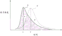
However, as shown in fig. 9, the quantitative determination of the gas component to be measured is calculated based on the area S of the chromatogram C, and therefore, the chromatogram C also needs to be corrected and adjusted. The area S of the chromatogram C is affected by deterioration of an ion source that ionizes a gas component, measurement temperature, and the like. Further, the shape of the chromatogram (time t at which the maximum peak is given) is affected by the heating rate (temperature increase rate) when the sample is heated, and when the shape of the chromatogram becomes C ', the shape changes to time t', and the area S 'of the chromatogram C' also changes.
The order of the correction and adjustment can be performed according to the instruction manual of the measurement device, but the general correction order is not necessarily optimal for the analysis of each measurement target substance, and additional correction and adjustment may be necessary depending on each measurement target substance. The correction and adjustment require professional knowledge, experience, and appropriate standard substances, and the work is complicated, which leads to a decrease in work efficiency.
Disclosure of Invention
The present invention has been made to solve the above-described problems, and an object of the present invention is to provide a method of calibrating a generated gas analyzer and a generated gas analyzer, which can easily correct a device error, a time error variation, and the like of detection sensitivity and can quantify a measurement target with high accuracy.
In order to achieve the above object, the present invention provides a method for calibrating a generated gas analyzer, including: a heating unit that heats a sample to generate a gas component; an ion source that ionizes the gas component generated by the heating portion to generate ions; a mass spectrometer for detecting the gas component by mass-analyzing the ions; the calibration method for the generated gas analyzer is characterized in that a standard sample containing the gas component as a measurement object is used, (1) calibration is performed so that a spectral position corresponding to a mass-to-charge ratio m/z of a mass spectrum obtained with respect to the gas component of the standard sample coincides with a reference spectral position, (2) after the calibration of the above (1), a sensitivity correction coefficient Cs = Ss/S when an area of a chromatogram of the actual gas component of the sample is measured is calculated from an area S of the chromatogram, which represents an intensity with respect to a holding time obtained with respect to the gas component of the standard sample, and a reference area Ss, (3) a heating correction coefficient H = t/ts, which corrects a heating speed of the sample in the heating portion when the gas component of the actual sample is measured, is calculated from a time t at which a maximum peak is given by the chromatogram and a reference time ts .
According to the calibration method of the generated gas analyzer, since the instrumental error, the temporal error variation, and the like of the detection sensitivity of the spectral position of the mass spectrum of each gas component are first calibrated according to the above (1), the chromatograms of each gas component of (2) and (3) can be obtained with high accuracy.
Next, since the area of the chromatogram is affected by deterioration of an ion source that ionizes a gas component, measurement temperature, and the like, the calibration in (2) is required. Therefore, according to (2), the area of the chromatogram of the actual gas component can be corrected by the sensitivity correction coefficient Cs, and the gas component can be accurately quantified from the area.
Next, when the heating rate (temperature increase rate) at the time of heating the sample is changed, the shape of the chromatogram (time t at which the maximum peak is given) is changed, and the area of the chromatogram is also changed, so that the correction by (3) is required. Therefore, by (3) appropriately adjusting the heating condition of the heating portion by the heating correction coefficient H and measuring, an accurate chromatogram can be obtained, and in addition to the correction by (2), more accurate quantification of the gas component can be performed.
By performing the corrections (2) to (3) one standard sample at a time before measuring an actual sample, the measurement target can be quantified with high accuracy, and the measurement target can be quantified with high reproducibility while suppressing errors in the instrument and time.
When the measurement target includes a plurality of gas components, the heating correction coefficient H = ∑ ai × ti/tsi (where i is a natural number indicating each gas component i, ai is a known heating sensitivity coefficient of each gas component i, ti is a time at which a maximum peak is given in a chromatogram of each gas component i, and tsi is a reference time at which a maximum peak is given in a chromatogram of each gas component i) may be calculated
According to the calibration method for the generated gas analyzing apparatus, even when the measurement target includes a plurality of gas components, the gas components can be accurately quantified.
The generated gas analyzing apparatus of the present invention includes: a heating unit that heats a sample to generate a gas component; an ion source that ionizes the gas component generated by the heating portion to generate ions; a mass spectrometer for detecting the gas component by mass-analyzing the ions; the method is characterized by further comprising, when using a standard sample containing the gas component as a measurement target, (1) performing correction so that a spectral position corresponding to a mass-to-charge ratio m/z of a mass spectrum obtained with respect to the gas component of the standard sample coincides with a reference spectral position, (2) calculating, after the correction of the step (1), a sensitivity correction coefficient Cs = Ss/S when measuring an area of a chromatogram of the gas component of an actual sample from an area S of the chromatogram, which represents an intensity with respect to a holding time obtained with respect to the gas component of the standard sample, and a reference area Ss, and (3) calculating, from a time t at which a maximum peak is given to the chromatogram and a reference time ts, a heating coefficient H = t/ts which corrects a heating rate of the sample in the heating portion when measuring the gas component of the actual sample, the above calculations are all performed by a computer.
According to the present invention, it is possible to easily correct instrument errors, time error variations, and the like in the detection sensitivity of a generated gas analyzer, and to quantify a measurement target with high accuracy. Further, the calibration and adjustment of the apparatus suitable for the measurement target substance can be performed without professional knowledge or experience.
Drawings
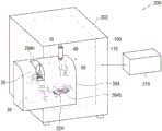
Fig. 1 is a perspective view showing the structure of a generated gas analyzing apparatus according to an embodiment of the present invention.
Fig. 2 is a perspective view showing the structure of the gas generating section.
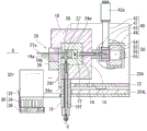
Fig. 3 is a vertical sectional view showing the structure of the gas generating section.
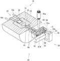
Fig. 4 is a cross-sectional view showing the structure of the gas generating section.
Fig. 5 is a block diagram showing an analysis operation of a gas component by the generated gas analyzer.
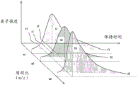
Fig. 6 is a diagram showing a method of calibrating a generated gas analyzer according to an embodiment of the present invention.
Fig. 7 is another diagram illustrating a method of calibrating a generated gas analyzer according to an embodiment of the present invention.
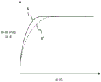
Fig. 8 is a diagram showing an example of correcting the heating speed of the sample in the heating furnace by the heating correction coefficient H.
Fig. 9 is a diagram showing a change in the shape of a chromatogram in mass analysis due to the influence of the heating rate of a sample.
Detailed Description
Embodiments of the present invention will be described below with reference to the drawings. Fig. 1 is a perspective view showing a structure of a generated gas analyzing apparatus 200 according to an embodiment of the present invention, fig. 2 is a perspective view showing a structure of a gas generating unit 100, fig. 3 is a vertical sectional view along an axial center O showing the structure of the gas generating unit 100, and fig. 4 is a horizontal sectional view along the axial center O showing the structure of the gas generating unit 100.
The generated gas analyzing apparatus 200 includes: a main body 202 serving as a housing, a box-shaped gas generating unit mounting portion 204 mounted on the front surface of the main body 202, and a computer (control unit) 210 for controlling the whole. The computer 210 has: a CPU for processing data; a storage unit for storing a computer program and data; a monitor; an input unit such as a keyboard. The computer 210 corresponds to a "correction processing unit".
The gas generation unit 100 is housed in the gas generation unit mounting portion 204, and the gas generation unit 100 is formed as an assembly of a cylindrical heating furnace (heating unit) 10, a sample holder 20, a cooling unit 30, a flow divider 40 for branching a gas, and an ion source 50. Further, a mass spectrometer (detection means) 110 for analyzing a gas component generated by heating a sample is housed in the main body 202.
Further, since the opening 204h is provided from the upper surface toward the front surface of the gas generation unit mounting portion 204, and the sample holder 20 is positioned at the opening 204h when moved to a discharge position (described later) outside the heating furnace 10, the sample can be taken out of or put into the sample holder 20 from the opening 204 h. Further, a slit 204s is provided on the front surface of the gas generating unit mounting portion 204, and the sample holder 20 is moved inside and outside the heating furnace 10 by moving the opening/closing handle 22H exposed to the outside from the slit 204s in the left and right directions to be set at the discharge position, and the sample is taken out or put in.
Further, if the sample holder 20 is moved on a movement rail 204L (described later) by, for example, a stepping motor or the like controlled by the computer 210, the function of moving the sample holder 20 inside and outside the heating furnace 10 can be automated.
Next, the structure of each part of the gas generating unit 100 will be described with reference to fig. 2 to 5.
First, the heating furnace 10 is attached to the attachment plate 204a of the gas generating portion attachment portion 204 with the axis O horizontal, and includes: a substantially cylindrical heating chamber 12 opened with an axis O as a center; a heating block 14; an insulating jacket 16.
A heating block 14 is disposed on the outer periphery of the heating chamber 12, and a jacket 16 is disposed on the outer periphery of the heating block 14. The heating block 14 is made of aluminum, and is electrically heated by a pair of heaters 14a (see fig. 4) extending to the outside of the heating furnace 10 along the axial center O.
The mounting plate 204a extends in a direction perpendicular to the axis O, and the flow splitter 40 and the ion source 50 are mounted on the heating furnace 10. Further, the ion source 50 is supported by a support column 204b extending in the vertical direction of the gas generating section mounting portion 204.
A diverter 40 is connected to the side of the heating furnace opposite to the opening side (the right side in fig. 3). A carrier gas protection pipe 18 is connected to the lower side of the heating furnace 10, and a carrier gas flow path 18f that communicates with the lower surface of the heating chamber 12 and introduces the carrier gas C into the heating chamber 12 is housed in the carrier gas protection pipe 18.
As will be described in detail later, the gas flow path 41 communicates with an end surface of the heating chamber 12 on the side opposite to the opening side (the right side in fig. 3), and the mixed gas M of the gas component G and the carrier gas C generated in the heating furnace 10 (the heating chamber 12) flows through the gas flow path 41.
The sample holder 20 has: a stage 22 that moves on a movement rail 204L attached to the inner upper surface of the gas generation unit attachment portion 204; a bracket 24c attached to the table 22 and extending vertically; heat insulators 24b and 26 attached to the front surface (left side in fig. 3) of the bracket 24 c; a sample holding portion 24a extending from the bracket 24c toward the heating chamber 12 side in the axial center O direction; a heater 27 embedded slightly below the sample holding portion 24 a; the sample tray 28 is disposed on the upper surface of the sample holding portion 24a slightly above the heater 27, and stores a sample.
Here, the movement rail 204L extends in the axial center O direction (the left-right direction in fig. 3), and the sample holder 20 moves forward and backward in the axial center O direction together with the stage 22. The opening/closing handle 22H is attached to the base 22 so as to extend in a direction perpendicular to the axial center O direction.
The bracket 24c is elongated in shape having a semicircular upper portion, the heat insulator 24b is attached to a front surface of the upper portion of the bracket 24c in a substantially cylindrical shape (see fig. 2), and the electrode 27a of the heater 27 penetrates the heat insulator 24b and projects to the outside. The heat insulator 26 has a substantially rectangular shape, and is attached to the front surface of the bracket 24c below the heat insulator 24 b. The heat insulator 26 is not mounted below the bracket 24c, and the front surface of the bracket 24c is exposed to form a contact surface 24 f.
The bracket 24c is formed to have a slightly larger diameter than the heating chamber 12 so as to airtightly close the heating chamber 12, and the sample holding portion 24a is housed inside the heating chamber 12.
The sample on the sample disk 28 placed inside the heating chamber 12 is heated in the heating furnace 10, and a gas component G is generated.
The cooling unit 30 is disposed outside the heating furnace 10 (on the left side of the heating furnace 10 in fig. 3) so as to face the heat transfer block 26 of the sample holder 20. The cooling unit 30 includes: a cooling block 32 having a substantially rectangular shape and a concave portion 32 r; cooling fins 34 attached to the lower surface of the cooling block 32; and an air cooling fan 36 connected to the lower surface of cooling fin 34 and supplying air to cooling fin 34.
When the sample holder 20 moves toward the left side in fig. 3 along the axis O direction on the moving rail 204L and is discharged outside the heating furnace 10, the contact surface 24f of the carrier 24c is accommodated in and brought into contact with the concave portion 32r of the cooling block 32, and the heat of the carrier 24c is taken away via the cooling block 32, thereby cooling the sample holder 20 (particularly, the sample holding portion 24 a).
In the present embodiment, the sample holder 20 (including the bracket 24 c) and the cooling block 32 are both made of aluminum.
As shown in fig. 3 and 4, the flow divider 40 includes: the gas flow path 41 communicating with the heating chamber 12; a branch passage 42 communicating with the gas flow passage 41 and opening to the outside; a mass flow controller (discharge flow rate adjusting mechanism) 42a connected to the outlet side of the branch passage 42 to adjust the discharge flow rate of the mixed gas M from the branch passage 42 to the outside; a frame portion 43 opened in the internal gas flow path 41; and a heat retaining portion 44 surrounding the frame portion 43.
As shown in fig. 4, the gas flow path 41 has a curved shape as follows when viewed from the top surface: after extending in the axis O direction while communicating with the heating chamber 12, the heating chamber is bent in the direction perpendicular to the axis O, and further bent in the axis O direction to reach the terminal portion 41 e. The gas flow path 41 has a diameter enlarged near the center of a portion extending perpendicular to the axis O direction to form a branch chamber 41M. The branch chamber 41M extends to the upper surface of the housing 43, and a branch passage 42 having a diameter slightly smaller than that of the branch chamber 41M is fitted thereto.
The gas flow path 41 may be linear, which communicates with the heating chamber 12 and extends along the axis O to reach the terminal end 41e, or may be curved or linear with an angle with respect to the axis O in accordance with the positional relationship between the heating chamber 12 and the ion source 50.
In the present embodiment, the gas flow path 41 is formed to have a diameter of about 2mm, and the branch chamber 41M and the branch path 42 are formed to have a diameter of about 1.5 mm. The ratio (split ratio) of the flow rate flowing to the terminal end portion 41e in the gas flow path 41 to the flow rate branched into the branch path 42 is determined by each flow path resistance, and a larger amount of the mixed gas M can be discharged into the branch path 42. The flow dividing ratio can be controlled by adjusting the opening degree of the mass flow controller 42 a.
As shown in fig. 3 and 4, the ion source 50 includes: a frame 53, a heat retaining part 54 surrounding the frame 53, a discharge needle 56, and a holder 55 holding the discharge needle 56. The frame portion 53 has a plate shape, and a small hole 53C is formed through the plate surface thereof in the axial center O direction and at the center. The terminal end 41e of the gas flow path 41 passes through the inside of the frame 53 and faces the side wall of the small hole 53C. On the other hand, the discharge needle 56 extends perpendicularly to the axial center O and faces the small hole 53C.
Then, in the mixed gas M introduced from the terminal end portion 41e to the vicinity of the orifice 53C, the gas component G is ionized by the discharge needle 56.
The ion source 50 is a well-known device, and in the present embodiment, is of the Atmospheric Pressure Chemical Ionization (APCI) type. APCI is preferable because it is less likely to cause fragmentation of the gas component G and does not generate a fragmentation peak, and therefore, it is possible to detect a measurement target without separation in chromatography or the like.
The gas component G ionized by the ion source 50 is introduced into the mass spectrometer 110 together with the carrier gas C and analyzed.
The ion source 50 is housed inside the heat retaining portion 54.
Fig. 5 is a block diagram showing an analysis operation of a gas component by the generated gas analyzer 200.
The sample S is heated in the heating chamber 12 of the heating furnace 10 to generate a gas component G. The heating state (temperature increase rate, maximum reached temperature, etc.) of the heating furnace 10 is controlled by the heating control unit 212 of the computer 210.
The gas component G is mixed with the carrier gas C introduced into the heating chamber 12 to be a mixed gas M, and is introduced into the flow divider 40. The detection signal determination unit 214 of the computer 210 receives a detection signal from the detector 118 (described later) of the mass spectrometer 110.
The flow rate control unit 216 determines whether or not the peak intensity of the detection signal received from the detection signal determination unit 214 is outside the threshold range. Next, when the flow rate is out of the range, the flow rate control unit 216 controls the opening degree of the mass flow controller 42a to adjust the flow rate of the mixed gas M discharged from the branch passage 42 to the outside in the flow divider 40, and further adjusts the flow rate of the mixed gas M introduced from the gas passage 41 to the ion source 50, thereby maintaining the detection accuracy of the mass spectrometer 110 to be optimum.
The mass spectrometer 110 includes: a first pore 111 into which the gas component G ionized by the ion source 50 is introduced; a second pore 112 connected to the first pore 111 and through which the gas component G sequentially flows; an ion guide 114; a quaternary mass filter 116; and a detector 118 for detecting the gas component G from the quaternary mass filter 116.
The four-stage mass filter 116 changes the applied high-frequency voltage to enable mass scanning, and generates a four-stage electric field in which ions are vibrated to detect the ions. The four-stage mass filter 116 is a mass separator that transmits only the gas component G in a specific mass range, and therefore the gas component G can be identified and quantified by the detector 118.
In addition, it is preferable to use a selective ion detection (SIM) mode in which only ions having a specific mass-to-charge ratio (m/z) in a gas component to be measured are detected, because the detection accuracy of the gas component to be measured is improved as compared with a full ion detection (scan) mode in which ions having a mass-to-charge ratio in a certain range are detected.
Next, a method of calibrating a generated gas analyzer according to an embodiment of the present invention will be described with reference to fig. 6.
First, a standard sample containing a gas component as a measurement target is prepared. In the present embodiment, the measurement target includes a plurality of gas components, and the standard sample includes these plurality of gas components (for example, phthalate esters of four components of DEHP, DBP, BBP, DIBP, which are targets of RoHS restriction). The content ratio of each gas component contained in the standard sample is not limited, and may be close to the content ratio assumed for the actual gas component to be measured (for example, the RoHS limit values of four components, DEHP, DBP, BBP, and DIBP, are 1000ppm and the same, and therefore, the content ratios of the four components are preferably set to the same number of digits). The content is (mass of gas component)/(mass of the whole sample).
Subsequently, the correction was performed in the following procedure.
(1) The calibration is performed so that the spectral position corresponding to the mass-to-charge ratio m/z of the mass spectrum obtained for each gas component of the standard sample coincides with the reference spectral position. For example, the setting (e.g., high-frequency voltage) of the mass spectrometer 110 (quaternary mass filter 116) is adjusted so that each spectral position of the mass spectrum obtained in fig. 6 with respect to the three gas components 1, 2, 3, respectively, falls within the allowable range 2L of the reference spectral positions m1, m2, m 3.
As shown in fig. 7, the allowable range 2L is a range centered on the reference spectrum positions m1, m2, and m3 as ± L, and the spectrum positions of the gas components of the standard sample may fall within the allowable range 2L. This is because, in the present embodiment, the types of the respective gas components contained in the standard sample are predetermined, and therefore, there is no problem even if debugging is not performed to minimize the error from the reference spectrum positions of the plurality of components, as in the case of the general-purpose analysis in which the measurement target is not limited. However, the method of matching each spectrum position with the reference spectrum position is not limited to the above, and such debugging and the like may be performed.
In this way, instrument errors, time error variations, and the like in the detection sensitivity of the spectral position of the mass spectrum of each gas component are corrected, and therefore, the chromatograms of each gas component in the following (2) and (3) can be obtained with high accuracy.
(2) After the correction of (1), the sensitivity correction coefficient Cs = Ss/S is calculated from the area S of the chromatogram showing the intensity (ion intensity) with respect to the retention time obtained with respect to the gas component of the standard sample and the reference area Ss. Cs is a correction coefficient for measuring the area of the chromatogram of the actual gas component of the sample. The area S of the chromatogram is affected by deterioration of an ion source that ionizes a gas component, measurement temperature, and the like, and therefore the correction by (2) is necessary.
For example, in fig. 6, chromatograms C1, C2, and C3 can be obtained for the three gas components 1, 2, and 3, respectively, and therefore the CPU of the computer 210 determines the areas S1, S2, and S3 of the chromatograms C1, C2, and C3. On the other hand, the reference areas Ss1, Ss2, and Ss3 of the gas components C1, C2, and C3 are stored in the storage unit of the computer 210. Therefore, the CPU calculates Cs for each of the gas components C1, C2, and C3 (for example, Cs1= Ss1/S1 in the case of the gas component C1), and takes the value obtained by multiplying the area of the chromatogram of the actual gas component C1 by Cs1 as the area. From this area, the gas component C1 can be accurately quantified.
(3) The heating correction coefficient H = t/ts for correcting the heating speed of the sample in the heating furnace 10 (actually, on the sample disk 28 at the monitored temperature) is calculated from the time t of the maximum peak value and the reference time ts of the chromatograms C1, C2, and C3. H is a coefficient for adjusting the heating rate of the sample in the heating furnace 10 when the gas component of the actual sample is measured thereafter. When the heating rate (temperature increase rate) at the time of heating the sample is changed, the shape of the chromatogram (time t at which the maximum peak is given) is changed, and the area of the chromatogram is also changed, so that the correction by (3) is required.
For example, in fig. 6, the CPU determines times t1, t2, and t3 for the respective color spectra C1, C2, and C3. On the other hand, the reference times ts1, ts2, and ts3 for the gas components C1, C2, and C3 are stored in the storage unit of the computer 210. Therefore, the CPU calculates H = t/ts for each of the gas components C1, C2, and C3.
The heating conditions in the heating furnace 10 were appropriately adjusted by the H, and the actual gas component C1 of the sample was measured, whereby an accurate chromatogram could be obtained. Then, the actual area value is obtained by multiplying the area of the chromatogram by the sensitivity correction coefficient Cs1 of the gas component C1 specified in (2), whereby the gas component C1 can be quantified more accurately. Thus, by using the standard sample, it is possible to easily correct instrument errors such as heating capability of the heating furnace 10 and the heater 27 of the generated gas analyzer 200, measurement temperature, detection sensitivity, and time error variations, thereby improving the measurement accuracy (particularly, the area of the chromatogram).
In the heating furnace 10, the temperature of the heating furnace 10 itself is actually kept at a predetermined temperature by the heater 14a, the sample temperature is monitored by the resistance of the heater 27 located slightly below the sample tray 28, and the heating rate of the sample is adjusted according to the monitored sample temperature by the heater 27. Therefore, the phrase "correcting the heating rate of the sample in the heating furnace" means that the heating rate of the portion (heater 27 in this example) whose heating state is varied is corrected at least in accordance with the sample temperature.
Here, when the measurement target contains a plurality of gas components, H =Σai × ti/tsi is calculated. Where i is a natural number indicating each gas component i, and corresponds to gas components 1, 2, and 3 in the present embodiment. Ai is a known heating sensitivity coefficient of each gas component i, and indicates how easily the peak time (time t at which the maximum peak is given) of each gas component changes with respect to a change in the heating rate. ai corresponds to the heating sensitivity coefficients a1, a2, a3 for each of the gas components 1, 2, 3 in the present embodiment. tsi is a reference time at which the chromatogram of each gas component i gives the maximum peak, and in the present embodiment, corresponds to the reference times ts1, ts2, ts3 at which the chromatograms C1, C2, C3 give the maximum peak for each of the gas components 1, 2, 3.
Therefore, H = (a 1 × t1/ts 1) + (a 2 × t2/ts 2) + (a 3 × t3/ts 3).
Fig. 8 shows an example of correcting the heating rate of the sample in the heating furnace 10 by the heating correction coefficient H. For example, when the actual time t for giving the maximum peak is shorter than the reference time ts (H < 1), the heating rate becomes excessive, and the heating rate needs to be decreased compared to the original heating mode U. Therefore, the heating correction coefficient H is multiplied by the gradient (heating rate) of the original heating program to correct the heating pattern U' with the heating rate reduced.
In general, when the heating rate of the heater 27 is too high, the gas concentration of the gas component increases rapidly, and therefore the ionization efficiency in the ion source tends to be unable to follow this, and the peak area value tends to decrease. Therefore, the correct color spectrum can be obtained by correcting the heating pattern U'.
When the processes (1) to (3) are automatically performed by the correction processing unit 210, the following method is used.
(1) The detection signal determination unit 214 adjusts the setting (for example, high-frequency voltage) of the mass spectrometer 110 (the four-stage mass filter 116) based on the received detection signal so that the spectral positions of the gas components of the standard sample fall within m1, m2, m3, and the allowable range 2L, which are preset in the storage unit.
(2) The detection signal determination unit 214 calculates the sensitivity correction coefficient Cs based on the received detection signal and the reference areas Ss1, Ss2, and Ss3 set in the storage unit. The calculated Cs is stored in the storage unit.
(3) The detection signal determination unit 214 calculates the heating correction coefficient H = t/ts based on the received detection signal and the reference time ts set in the storage unit. The calculated H is stored in a storage unit.
Next, when performing actual mass analysis of the gas component of the sample, the heating control unit 212 corrects the heating rate of the sample in the heating furnace 10 by controlling the heater 27 based on H, and performs measurement in this state. The detection signal determination unit 214 then outputs the value obtained by multiplying the area of the obtained chromatogram by Cs1 as an area value.
Needless to say, the present invention is not limited to the above embodiments, and various modifications and equivalents included in the spirit and scope of the present invention are also included.
As the object of measurement, bromide flame retardants (polybrominated biphenyls (PBBs), polybrominated diphenyl ethers (PBDEs)) restricted by the european regulation of specific hazardous substances (RoHS) can be exemplified in addition to phthalates, but not limited thereto.
The structures, shapes, arrangement states, and the like of the heating furnace, the ion source, and the mass spectrometer are not limited to the above examples. The method of correcting the spectrum position of the mass spectrum to match the reference spectrum position is not limited to the above example, and a known method may be used.
In the generated gas analyzing apparatus according to the present invention, the processes (1) to (3) may be automatically performed by providing an autosampler for automatically and continuously inserting a sample into the heating unit, providing a place for placing the standard sample at a predetermined position of the autosampler, and measuring the standard sample once at first.
Description of the reference numerals
10 a heating section (heating furnace); 50 an ion source; 110 mass analyzer; 200 generating gas analysis device; 210 a correction processing unit (computer); chromatography of C1, C2, C3 gas components; m1, m2, m3 reference spectral positions.
Claims (3)
1. A calibration method for a generated gas analysis device, the generated gas analysis device comprising:
a heating unit that heats a sample to generate a gas component;
an ion source that ionizes the gas component generated by the heating portion to generate ions;
a mass spectrometer for detecting the gas component by mass-analyzing the ions;
the calibration method for a generated gas analysis apparatus is characterized in that,
using a standard sample containing the gas component as a measurement target,
(1) performing calibration so that a spectral position corresponding to a mass-to-charge ratio m/z of a mass spectrum obtained with respect to the gas component of the standard sample coincides with a reference spectral position,
(2) after the correction of the above (1), calculating a sensitivity correction coefficient Cs = Ss/S for measuring an actual area of a chromatogram of the gas component of the sample from an area S of the chromatogram, which represents an intensity with respect to a retention time obtained with respect to the gas component of the standard sample, and a reference area Ss, and correcting the actual area of the chromatogram of the gas component of the sample using the sensitivity correction coefficient Cs,
(3) a heating correction coefficient H = t/ts for correcting the heating rate of the sample in the heating portion when the actual gas component of the sample is measured is calculated from the time t of the chromatogram at which the maximum peak is given and a reference time ts, and the heating rate of the sample in the heating portion when the actual gas component of the sample is measured is corrected by the heating correction coefficient H.
2. The method of calibrating a generated gas analyzing apparatus according to claim 1,
the measurement object contains a plurality of gas components,
the heating correction coefficient H = ∑ ai × ti/tsi is calculated,
where i is a natural number indicating each gas component i, ai is a known heating sensitivity coefficient of each gas component i, ti is a time at which the chromatogram of each gas component i gives a maximum peak, and tsi is a reference time at which the chromatogram of each gas component i gives a maximum peak.
3. A generated gas analysis device is provided with:
a heating unit that heats a sample to generate a gas component;
an ion source that ionizes the gas component generated by the heating portion to generate ions;
a mass spectrometer for detecting the gas component by mass-analyzing the ions;
it is characterized in that the preparation method is characterized in that,
and a correction processing part is also provided,
the correction processing part is provided with a computer,
when a standard sample containing the gas component as a measurement target is used,
(1) performing calibration so that a spectral position corresponding to a mass-to-charge ratio m/z of a mass spectrum obtained with respect to the gas component of the standard sample coincides with a reference spectral position,
(2) after the correction of the above (1), a sensitivity correction coefficient Cs = Ss/S is calculated for measuring an area Sr of a chromatogram of the actual gas component of the sample, the area S of the chromatogram representing an intensity with respect to a retention time obtained with respect to the gas component of the standard sample, and a reference area Ss, the sensitivity correction coefficient Cs correcting the area Sr of the chromatogram of the actual gas component of the sample,
(3) calculating a heating correction coefficient H = t/ts for correcting a heating speed Vr of the sample in the heating portion when the gas component of the sample is actually measured, from a time t at which the maximum peak is given in the chromatogram and a reference time ts,
the above-mentioned calculations are all carried out by a computer,
the area Sr of the chromatogram of the gas component of the actual sample and the heating speed Vr of the sample inside the heating portion at the time of measuring the gas component of the actual sample are corrected.
Applications Claiming Priority (2)
| Application Number | Priority Date | Filing Date | Title |
|---|---|---|---|
| JP2015227372A JP6622570B2 (en) | 2015-11-20 | 2015-11-20 | Method for calibrating evolved gas analyzer and evolved gas analyzer |
| JP2015-227372 | 2015-11-20 |
Publications (2)
| Publication Number | Publication Date |
|---|---|
| CN107064396A CN107064396A (en) | 2017-08-18 |
| CN107064396B true CN107064396B (en) | 2020-09-22 |
Family
ID=58720763
Family Applications (1)
| Application Number | Title | Priority Date | Filing Date |
|---|---|---|---|
| CN201611016224.7A Active CN107064396B (en) | 2015-11-20 | 2016-11-18 | Method for calibrating generated gas analyzing apparatus and generated gas analyzing apparatus |
Country Status (5)
| Country | Link |
|---|---|
| US (1) | US9897579B2 (en) |
| JP (1) | JP6622570B2 (en) |
| KR (1) | KR102143124B1 (en) |
| CN (1) | CN107064396B (en) |
| TW (1) | TWI700491B (en) |
Families Citing this family (6)
| Publication number | Priority date | Publication date | Assignee | Title |
|---|---|---|---|---|
| JP6622570B2 (en) * | 2015-11-20 | 2019-12-18 | 株式会社日立ハイテクサイエンス | Method for calibrating evolved gas analyzer and evolved gas analyzer |
| US9899198B2 (en) * | 2015-11-20 | 2018-02-20 | Hitachi High-Tech Science Corporation | Method for analyzing evolved gas and evolved gas analyzer |
| JP6505268B1 (en) * | 2018-01-11 | 2019-04-24 | 株式会社日立ハイテクサイエンス | Mass spectrometer and mass spectrometry method |
| WO2020066009A1 (en) * | 2018-09-28 | 2020-04-02 | 株式会社島津製作所 | Mass spectrometry device evaluation method, mass spectrometry device calibration method, analysis method, mass spectrometry device, and mass spectrometry reagent |
| CN109061025B (en) * | 2018-10-26 | 2021-08-10 | 苏州科技大学 | Method for detecting brominated flame retardant content in food |
| CN112067732B (en) * | 2020-09-19 | 2022-11-11 | 中国计量科学研究院 | Method for quantitatively detecting brominated flame retardant |
Citations (6)
| Publication number | Priority date | Publication date | Assignee | Title |
|---|---|---|---|---|
| US4814612A (en) * | 1983-08-30 | 1989-03-21 | Research Corporation | Method and means for vaporizing liquids for detection or analysis |
| JP2002005915A (en) * | 2000-06-22 | 2002-01-09 | Hitachi Ltd | Gas chromatographic device |
| EP1508911A1 (en) * | 2003-08-18 | 2005-02-23 | Rigaku Corporation | Evolved gas analysing method and apparatus |
| CN103282768A (en) * | 2010-12-28 | 2013-09-04 | 株式会社岛津制作所 | Chromatograph mass spectrometer |
| CN104428666A (en) * | 2012-08-24 | 2015-03-18 | 株式会社岛津制作所 | Liquid chromatograph and column oven used therefor |
| JP2015165223A (en) * | 2014-02-10 | 2015-09-17 | 電子科学株式会社 | Device and method for diagnosing deterioration of concrete |
Family Cites Families (18)
| Publication number | Priority date | Publication date | Assignee | Title |
|---|---|---|---|---|
| US4883958A (en) * | 1988-12-16 | 1989-11-28 | Vestec Corporation | Interface for coupling liquid chromatography to solid or gas phase detectors |
| JP3123843B2 (en) * | 1992-12-17 | 2001-01-15 | 日本電子株式会社 | Sample vaporizer using plasma flame |
| CN1088191C (en) * | 1996-09-01 | 2002-07-24 | 武汉钢铁(集团)公司 | Chromatographic column for analysis of three-component oil in tar and using method |
| JP2005106524A (en) | 2003-09-29 | 2005-04-21 | Tdk Corp | Standard sample, calibration method, analysis method, and method for manufacturing device |
| DE102005004325A1 (en) * | 2005-01-31 | 2006-08-10 | Bruker Daltonik Gmbh | Ion mobility spectrometer and method of its operation |
| WO2007007849A1 (en) * | 2005-07-14 | 2007-01-18 | Matsushita Electric Industrial Co., Ltd. | Analyzer and analyzing method |
| JP4958258B2 (en) * | 2006-03-17 | 2012-06-20 | 株式会社リガク | Gas analyzer |
| JP2008139130A (en) * | 2006-12-01 | 2008-06-19 | Hitachi Ltd | Real time analyzer and real time analyzing method |
| JP2008190898A (en) | 2007-02-01 | 2008-08-21 | Hitachi High-Technologies Corp | Quadruple mass spectrometer and mass calibration method therefor |
| JP5170650B2 (en) * | 2008-02-29 | 2013-03-27 | 株式会社リガク | Gas quantitative analysis method and gas quantitative analysis apparatus |
| IL193003A (en) * | 2008-07-23 | 2011-12-29 | Aviv Amirav | Open probe method and device for sample introduction for mass spectrometry analysis |
| WO2012029303A1 (en) * | 2010-08-31 | 2012-03-08 | アトナープ株式会社 | Device for preparing sample supplied to ion mobility sensor |
| JP5771458B2 (en) * | 2011-06-27 | 2015-09-02 | 株式会社日立ハイテクノロジーズ | Mass spectrometer and mass spectrometry method |
| TWI541492B (en) * | 2012-01-17 | 2016-07-11 | Mks儀器公司 | Method and apparatus for siloxane measurements in a biogas |
| JP6622570B2 (en) * | 2015-11-20 | 2019-12-18 | 株式会社日立ハイテクサイエンス | Method for calibrating evolved gas analyzer and evolved gas analyzer |
| US9831077B2 (en) * | 2015-11-20 | 2017-11-28 | Hitachi High-Tech Science Corporation | Method for analyzing evolved gas and evolved gas analyzer |
| US9899198B2 (en) * | 2015-11-20 | 2018-02-20 | Hitachi High-Tech Science Corporation | Method for analyzing evolved gas and evolved gas analyzer |
| US10401342B2 (en) * | 2015-11-20 | 2019-09-03 | Hitachi High-Tech Science Corporation | Evolved gas analyzer and method for analyzing evolved gas |
-
2015
- 2015-11-20 JP JP2015227372A patent/JP6622570B2/en active Active
-
2016
- 2016-09-12 TW TW105129605A patent/TWI700491B/en active
- 2016-10-14 KR KR1020160133532A patent/KR102143124B1/en active IP Right Grant
- 2016-11-18 CN CN201611016224.7A patent/CN107064396B/en active Active
- 2016-11-19 US US15/356,585 patent/US9897579B2/en active Active
Patent Citations (6)
| Publication number | Priority date | Publication date | Assignee | Title |
|---|---|---|---|---|
| US4814612A (en) * | 1983-08-30 | 1989-03-21 | Research Corporation | Method and means for vaporizing liquids for detection or analysis |
| JP2002005915A (en) * | 2000-06-22 | 2002-01-09 | Hitachi Ltd | Gas chromatographic device |
| EP1508911A1 (en) * | 2003-08-18 | 2005-02-23 | Rigaku Corporation | Evolved gas analysing method and apparatus |
| CN103282768A (en) * | 2010-12-28 | 2013-09-04 | 株式会社岛津制作所 | Chromatograph mass spectrometer |
| CN104428666A (en) * | 2012-08-24 | 2015-03-18 | 株式会社岛津制作所 | Liquid chromatograph and column oven used therefor |
| JP2015165223A (en) * | 2014-02-10 | 2015-09-17 | 電子科学株式会社 | Device and method for diagnosing deterioration of concrete |
Also Published As
| Publication number | Publication date |
|---|---|
| JP2017096695A (en) | 2017-06-01 |
| US9897579B2 (en) | 2018-02-20 |
| KR20170059383A (en) | 2017-05-30 |
| JP6622570B2 (en) | 2019-12-18 |
| TWI700491B (en) | 2020-08-01 |
| US20170146497A1 (en) | 2017-05-25 |
| CN107064396A (en) | 2017-08-18 |
| TW201723477A (en) | 2017-07-01 |
| KR102143124B1 (en) | 2020-08-10 |
Similar Documents
| Publication | Publication Date | Title |
|---|---|---|
| CN107064396B (en) | Method for calibrating generated gas analyzing apparatus and generated gas analyzing apparatus | |
| CN106970173B (en) | Method and apparatus for analyzing generated gas | |
| US9899198B2 (en) | Method for analyzing evolved gas and evolved gas analyzer | |
| TW201719165A (en) | Method for analyzing evolved gas and evolved gas analyzer | |
| CN109283265B (en) | Mass spectrometer and mass spectrometry method | |
| KR102556761B1 (en) | Apparatus and method for analyzing evolved gas | |
| JP6366657B2 (en) | Generated gas analyzer and generated gas analysis method | |
| CN110031582B (en) | Mass spectrometer and mass spectrometry method | |
| JP7055323B2 (en) | Mass spectrometer and mass spectrometry method | |
| JP2009187850A (en) | Mass spectroscope |
Legal Events
| Date | Code | Title | Description |
|---|---|---|---|
| PB01 | Publication | ||
| PB01 | Publication | ||
| SE01 | Entry into force of request for substantive examination | ||
| SE01 | Entry into force of request for substantive examination | ||
| GR01 | Patent grant | ||
| GR01 | Patent grant |