CN107059640B - Bridge girder erection machine for prefabricated segmental beam span-by-span construction and construction method thereof - Google Patents
Bridge girder erection machine for prefabricated segmental beam span-by-span construction and construction method thereof Download PDFInfo
- Publication number
- CN107059640B CN107059640B CN201710375077.0A CN201710375077A CN107059640B CN 107059640 B CN107059640 B CN 107059640B CN 201710375077 A CN201710375077 A CN 201710375077A CN 107059640 B CN107059640 B CN 107059640B
- Authority
- CN
- China
- Prior art keywords
- supporting leg
- main frame
- hanging
- main
- supporting
- Prior art date
- Legal status (The legal status is an assumption and is not a legal conclusion. Google has not performed a legal analysis and makes no representation as to the accuracy of the status listed.)
- Active
Links
Images


Classifications
-
- E—FIXED CONSTRUCTIONS
- E01—CONSTRUCTION OF ROADS, RAILWAYS, OR BRIDGES
- E01D—CONSTRUCTION OF BRIDGES, ELEVATED ROADWAYS OR VIADUCTS; ASSEMBLY OF BRIDGES
- E01D21/00—Methods or apparatus specially adapted for erecting or assembling bridges
Abstract
The invention discloses a bridge girder erection machine for prefabricated segmental beam span-by-span construction and a construction method thereof, the bridge girder erection machine for prefabricated segmental beam span-by-span construction comprises a main frame, a support leg system, a hanging system, a wet joint template system and an overhead traveling crane system, wherein the support leg system comprises a first support leg, a second support leg, a third support leg and a fourth support leg which are sequentially arranged below the main frame from front to back, the first support leg and the fourth support leg are respectively positioned at two ends of the main frame and used as auxiliary support legs, the second support leg and the third support leg are heavy-load support legs, the hanging system is connected to the bottom of the main frame, the wet joint template system is connected to the outer side of the main frame, and the overhead traveling crane system is arranged on a longitudinal moving track at the top of the main frame; the construction method of the bridge girder erection machine for the span-by-span construction of the prefabricated segmental girders comprises a girder erection process of the bridge girder erection machine and a hole passing process of the bridge girder erection machine. The invention meets the construction requirement of the high-speed railway prefabricated section beam and has the advantages of high construction efficiency, convenience and high efficiency.
Description
Technical Field
The invention relates to the technical field of high-speed railway construction, in particular to a bridge girder erection machine for prefabricated segmental beam span-by-span construction and a construction method thereof.
Background
With the rapid development of scientific technology and infrastructure in China, particularly in the construction and construction of high-speed railways, various types of bridge girder erection machines are widely applied, and the construction speed and the construction quality of railways are improved. However, sensitive areas such as highways, natural water source protection areas, military facilities and the like distributed along the railway are more, the construction conditions are complex, and higher requirements are provided for the capacity of the bridge girder erection machine to adapt to the lines.
Although the bridge girder erection machine is widely applied to the construction of high-speed railways at present, the existing disadvantages are unavoidable:
1. in the construction of the prefabricated segmental beam with wet joints by the existing bridge girder erection machine, when the wet joints are poured, templates need to be installed and removed manually, so that the construction efficiency is low and the labor cost is increased;
2. in the construction process of the existing bridge girder erection machine, due to condition limitation, a girder transporting vehicle feeds girders from the back of a bridge, and prefabricated section girders are required to be placed in a staggered manner when fully hanging the bottom of a main frame, so that the construction efficiency is reduced; after the whole span section beam is tensioned, the load of the suspender needs to be unloaded one by utilizing a hydraulic jack, so that the safety performance is reduced;
3. the support legs of the existing bridge girder erection machine are supported at the pier top position, a part Zhang Lakong interferes with the support legs, and the support legs are tensioned when passing through holes to the next span, so that the construction efficiency is influenced;
4. when the existing bridge girder erection machine passes through a hole, a counter weight needs to be added to improve the longitudinal stability of the whole machine, and the position for inverting the supporting legs needs the assistance of a large-tonnage crane.
Therefore, the requirement of special equipment for construction of the prefabricated section beam of the high-speed railway is more and more urgent.
Disclosure of Invention
The invention aims to solve the defects in the prior art and provides a bridge girder erection machine for prefabricated segmental girder span-by-span construction and a construction method thereof so as to meet the construction requirements of the prefabricated segmental girders of the high-speed railway.
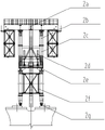
In order to solve the technical problems, the invention adopts the following technical scheme: a bridge girder erection machine for prefabricated segmental beam span-by-span construction comprises a main frame 1, a supporting leg system, a hanging system 8, a wet joint template system 9 and an overhead traveling crane system, wherein the supporting leg system comprises a first supporting leg 2, a second supporting leg 3, a third supporting leg 4 and a fourth supporting leg 5 which are sequentially arranged from front to back along the longitudinal direction below the main frame 1, the first supporting leg 2 and the fourth supporting leg 5 are respectively positioned at the two ends of the main frame 1 and used as auxiliary supporting legs, the second supporting leg 3 and the third supporting leg 4 are heavy-load supporting legs, the hanging system 8 is connected to the bottom of the main frame 1, the wet joint template system 9 is connected to the outer side of the main frame 1, the overhead traveling crane system is arranged on a longitudinal moving track at the top of the main frame 1,
the first support leg 2 comprises an upper cross beam 2a, a crank arm beam 2b, an outer sleeve column 2c, a jacking oil cylinder 2d, an inner sleeve column 2e, a connection frame 2f, an adjustable support 2g and a heightening joint 2h, wherein the upper cross beam 2a is connected with a main frame through a bolt, two symmetrical crank arm beams 2b are transversely arranged below the upper cross beam 2a, the upper part of the crank arm beam 2b is hinged with the upper cross beam 2a through a transverse pin shaft, the lower part of the crank arm beam 2b is connected with the outer sleeve column 2c through a bolt, the inner sleeve column 2e is slidably sleeved in the outer sleeve column 2c and is positioned and fixed through a positioning pin shaft, and the jacking oil cylinder 2d is connected between the inner sleeve column 2e and the outer sleeve column 2 c; the lower part of the inner sleeve column 2e is connected with a heightening section 2h through a bolt, and the bottom of the heightening section 2h is provided with an adjustable support 2g;
the second supporting leg 3 comprises a shifting trolley 3a, a cross beam 3b, upright posts 3c and a supporting oil cylinder 3d, the shifting trolley 3a is in sliding fit with the main frame 1, a lower track of the main frame 1 is directly arranged on a sliding seat of the shifting trolley 3a, a hydraulic pushing mechanism for pushing the shifting trolley 3a to move longitudinally is arranged between the shifting trolley 3a and the main frame 1, the shifting trolley 3a is installed on the cross beam 3b and forms transverse moving fit with the cross beam 3b, two symmetrical upright posts 3c are transversely arranged below the cross beam 3b, the upper part of each upright post 3c is connected with the cross beam 3b through a bolt, and the lower part of each upright post 3c is connected with the supporting oil cylinder 3d through a bolt;
the third supporting leg 4 comprises a shifting trolley 4a, a cross beam 4b and a supporting oil cylinder 4c, the shifting trolley 4a is in sliding fit with the main frame 1, the lower rail of the main frame 1 is directly arranged on a sliding seat of the shifting trolley 4a, a hydraulic pushing mechanism for pushing the shifting trolley 4a to move longitudinally is arranged between the shifting trolley 4a and the main frame 1, the shifting trolley 4a is installed on the cross beam 4b and forms transverse moving fit with the cross beam, and the supporting oil cylinder 4c is connected below the cross beam through a bolt;
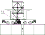
the fourth supporting leg 5 comprises an outer sleeve column 5a, a jacking oil cylinder 5b, an inner sleeve column 5c, a lower cross beam 5d and a traveling mechanism 5f, the outer sleeve column 5a is connected to the two transverse sides of the lower portion of the main frame 1 through bolts, the inner sleeve column 5c is slidably sleeved in the outer sleeve column 5a and is positioned and fixed through a positioning pin shaft, and the jacking oil cylinder 5b is connected between the inner sleeve column 5c and the outer sleeve column 5 a; the two inner sleeve columns 5c are connected through a lower cross beam 5 d;
the lower crossbeam 5d is divided into two sub-crossbeams by taking the center thereof as a boundary, the two sub-crossbeams are detachably and fixedly connected, a rack transmission mechanism is arranged between each sub-crossbeam and the inner sleeve column 5c and comprises a guide seat 5e arranged at the lower part of the inner sleeve column 5c, a driving gear 5g arranged on the guide seat 5e and a rack 5h transversely arranged on the sub-crossbeam, the sub-crossbeams are transversely matched with the corresponding guide seats 5e in a sliding manner, and the driving gear 5g is meshed with the corresponding racks 5 h; the bottom of each sub-beam is connected with a running mechanism 5f.
The overhead traveling crane system comprises a main overhead traveling crane 6 running on a longitudinal moving track outside the main frame 1 and an auxiliary overhead traveling crane 7 running on a longitudinal moving track inside the main frame 1, wherein the main overhead traveling crane 6 comprises a lifting system 6a, a transverse moving mechanism 6b, an overhead traveling crane portal 6c, a walking system 6d and an overhead traveling crane hanger 6e, the lifting system 6a is fixed on the transverse moving mechanism 6b, the transverse moving mechanism 6b is placed on a cross beam at the top of the overhead traveling crane portal 6c, the transverse moving mechanism 6b and the overhead traveling crane portal 6c can slide relatively, the overhead traveling crane portal 6c is connected with the walking system 6d, the lifting system 6a is connected with the overhead traveling crane hanger 6e through a steel wire rope, and the overhead traveling crane hanger 6e is provided with a three-dimensional adjusting device;
the auxiliary crown block 7 comprises a lifting system 7a, a crown block gantry 7b and a traveling system 7c, wherein the lifting system 7a is arranged on the crown block gantry 7b, and the crown block gantry 7b is connected with the traveling system 7c;
the hanging system 8 is composed of a plurality of hanging units, each hanging unit comprises a main cross beam 8a which is arranged below the main frame 1 through a hanging rod 8d, wherein a group of hanging units with longer hanging rods is called as long hanging, a group of hanging units with shorter hanging rods is called as short hanging, the upper part of the hanging rod 8d with long hanging penetrates through a bracket on the outer side of the main frame 1 and is clamped with the bracket through a matched fastening nut, and the upper part of the hanging rod 8d with short hanging penetrates through the main frame 1 and is clamped with the main frame 1 through a matched fastening nut;
four hanging rods 8d are arranged on each hanging unit, two hanging rods are arranged on the left side of the main cross beam 8a at intervals and connected with the main cross beam 8a through a fixing seat 8c, the fixing seat 8c comprises a fixing seat lower seat fixedly connected with the main cross beam 8a and a fixing seat upper seat connected with the two corresponding hanging rods, and the fixing seat upper seat is rigidly connected with the fixing seat lower seat; the other two suspenders are arranged on the right side of the main cross beam 8a at intervals and connected with the main cross beam 8a through hinged supports 8b, each hinged support 8b comprises a hinged support lower seat fixedly connected with the main cross beam 8a and a hinged support upper seat connected with the corresponding two suspenders, and the hinged support upper seats are hinged with the hinged support lower seats through hinge pins;
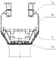
the wet joint formwork system 9 comprises a hydraulic oil cylinder 9a, hanging outer ribs 9b, side formwork systems 9c and a bottom formwork system 9d, at least one group of hanging outer rib units are longitudinally arranged on the main frame 1, each group of hanging outer rib unit comprises two hanging outer ribs 9b which are respectively arranged on the left side and the right side of the main frame 1, the hanging outer ribs 9b are hinged with the outer side of the main frame 1, the hydraulic oil cylinder 9a is connected between the hanging outer ribs 9b and the main frame 1 to form a rotatable system, and the side formwork systems 9c and the bottom formwork system 9d are connected with the hanging outer ribs 9b through adjusting support rods;
when the wet joint template system is in a mold closing state, two hanging outer ribs 9b of the same group of hanging outer rib units drive a side mold system 9c and a bottom mold system 9d connected with the hanging outer rib units to be in butt joint; when the wet joint template system is in the mold opening state, the two hanging outer ribs 9b of the same group of hanging outer rib units drive the side mold system 9c and the bottom mold system 9d connected with the hanging outer rib units to separate;
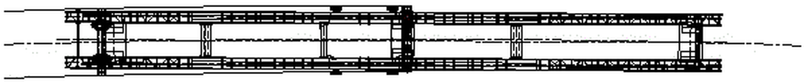
the main frame 1 comprises a box girder 1a and truss guide beams 1b fixedly connected to two ends of the box girder 1a, the main frame 1 is transversely of a symmetrical structure, and the middle of the main frame is connected by a beam connecting mechanism; two longitudinal moving rails are arranged on the top surface of the main frame 1 and are used for a main overhead traveling crane 6 and an auxiliary overhead traveling crane 7 to travel;
the connecting beam mechanism comprises two connecting beams 11c arranged corresponding to the second supporting leg 3 and the third supporting leg 4, two connecting beams 21d arranged in the middle of the main frame 1 and a connecting beam 31e arranged at the rear end of the main frame 1, the connecting beams 11c are of a box-shaped structure and are connected with the box-shaped main beam 1a through bolts, the connecting beams 21d are of the box-shaped structure and are connected with the box-shaped main beam 1a through pin shafts to form transverse rotation fit, and the connecting beams 31e are of a truss structure and are connected with the truss guide beam 1b through pin shafts.
The side part of the second supporting leg 3 is provided with an anchoring support rod 3e for anchoring with pre-embedded threaded steel bars on the erected bridge floor or pier top;
the upright posts 3c of the second supporting leg 3 are of an L-shaped structure, two supporting oil cylinders 3d are arranged below each upright post 3c, the two corresponding supporting oil cylinders 3d are arranged in a box beam below the upright post 3c, and the supporting oil cylinders and the matched bearing hoops form a jacking device of the second supporting leg 3.
The side part of the third supporting leg 4 is provided with an anchoring support rod 4d which is anchored with the built-in threaded steel bar on the erected bridge floor or pier top;
four supporting oil cylinders 4c are arranged below the third supporting leg 4, and the four supporting oil cylinders 4c are arranged in a box beam of the cross beam 4b and form a jacking device of the third supporting leg 4 together with a matched bearing hoop.
The hanging system 8 is composed of two sets of long hanging and nine sets of short hanging, wherein one set of short hanging is positioned at the central position, the longitudinal outer sides of the short hanging are respectively symmetrically provided with two sets of long hanging, and the longitudinal outer sides of the two sets of long hanging are respectively symmetrically provided with the remaining eight sets of short hanging.
And anchoring pin shafts are respectively arranged between the second supporting leg 3 and the third supporting leg 4 and the main frame 1.
Two heightening sections 2h corresponding to the first supporting leg 2 are connected by a connecting frame 2 f.
Another object of the present invention is to provide a construction method of a bridge girder erection machine for span-by-span construction of precast segmental girders, comprising the steps of: 1) Carrying out girder erection operation according to a girder erection procedure of a bridge girder erection machine;
2) Carrying out hole passing operation according to a hole passing process of a bridge girder erection machine;
3) According to the length of the bridge, performing cycle operation from the step 1 to the step 2 until a construction section is completed;
the process of erecting the bridge girder of the bridge erecting machine is carried out according to the following steps in sequence:
the method comprises the following steps:
1. the bridge girder erection machine is in place through the hole, the main frame connecting beam 21d is opened, and girder erection is prepared;
2. the girder transporting vehicle transports the section girders to the tail part of the bridge erecting machine, the main crown block 6 lifts the girders, and the first section girders to the eighth section girders are sequentially arranged on the short hangers below the main frame 1;
3. closing the main frame tie beams 21d;
step two:
1. the main crown block 6 is arranged on a long hanger below the main frame 1 from a ninth section beam to a tenth section beam;
2. the main overhead crane 6 lifts the section eleventh beam and is suspended on a short suspension below the main frame 1 after rotating;
3. the main crown block 6 lifts the long hangers corresponding to the ninth section beam to the tenth section beam to enable the section beams to be assembled;
step three:
1. sequentially adjusting the three-dimensional postures of the section beams by using the main overhead crane 6 to finish accurate alignment → adjustment of the size of the wet joint → installation of the wet joint template → pouring of the wet joint concrete → achievement of strength design requirement of the wet joint concrete → tensioning of the prestressed reinforcement bundle → opening of the wet joint template;
2. after the whole hole is tensioned, the jacking oil cylinders of the second supporting leg 3 and the third supporting leg 4 contract, the whole machine is unloaded, the hanging system 8 is disassembled, and the main beam 8a of the hanging system 8 is lifted to a beam transporting vehicle by using the auxiliary crown block 7 before the hole is drilled by the bridge erecting machine and transported to a beam yard;
the process of the bridge girder erection machine via hole is carried out according to the following steps in sequence:
the method comprises the following steps:
1. preparing a via hole by a bridge girder erection machine;
2. all the hanger rods 8d of the hanging system are lifted upwards by a preset distance;
3. anchoring the second support leg 3 and the No. 1 section Liang Liangmian embedded threaded steel bars by using the support rods;
step two:
1. when holes are drilled, the second supporting leg 3 and the third supporting leg 4 are supported, the first supporting leg 2 and the fourth supporting leg 5 are in a free state, the main crown block 6 and the auxiliary crown block 7 run above the third supporting leg 4, and the main frame 1 is pushed to move forwards and longitudinally by utilizing the hydraulic pushing mechanisms of the second supporting leg 3 and the third supporting leg 4 until the first supporting leg 2 reaches the front pier top supporting position;
2. adjusting the oil cylinder of the first supporting leg 2 to enable the first supporting leg 2 to be supported on the top of the front square pier;
step three:
1. the main crown block 6 and the auxiliary crown block 7 move above the second supporting leg 3, the first supporting leg 2, the second supporting leg 3 and the fourth supporting leg 5 are supported, and the oil cylinder of the third supporting leg 4 is contracted to enable the third supporting leg 4 to be in a free state;
2. starting a hydraulic pushing mechanism of the third supporting leg 4, enabling the third supporting leg 4 to automatically pass through a hole to reach the position of the erected bridge floor in front and be 2 meters away from the center of the pier, supporting the third supporting leg 4, and anchoring the third supporting leg and the beam surface;
step four:
1. the anchoring of the second supporting leg 3 and the beam surface is released, the first supporting leg 2, the third supporting leg 4 and the fourth supporting leg 5 are supported, and the oil cylinder of the second supporting leg 3 is contracted to enable the second supporting leg 3 to be in a free state;
2. starting a hydraulic pushing mechanism of the second supporting leg 3, enabling the second supporting leg 3 to pass through the hole to the front pier top, supporting the second supporting leg 3 on the front cushion stone, and anchoring the second supporting leg 3 and the pier top embedded threaded steel bar by using an anchoring support rod 3e;
step five:
1. the main crown block 6 and the auxiliary crown block 7 run to the front truss guide beam position, a track is laid on a bridge surface supported by a fourth supporting leg (5), a second supporting leg 3, a third supporting leg 4 and the fourth supporting leg 5 are supported, the first supporting leg 2 is emptied, and a hydraulic pushing mechanism of the second supporting leg 3 and the third supporting leg 4 is started to push the main frame 1 to longitudinally move for a preset distance and then is paused;
2. the oil cylinder of the fourth supporting leg 5 is contracted, and the fourth supporting leg 5, the second supporting leg 3 and the third supporting leg 4 are emptied;
step six:
1. starting hydraulic pushing mechanisms of a second supporting leg 3 and a third supporting leg 4 to push the main frame 1 to longitudinally move until the position of a frame beam is reached;
2. the bridge girder erection machine is in place through the through hole, the second supporting leg 3, the third supporting leg 4 and the anchoring pin shaft of the main frame 1 are connected, anchoring of the second supporting leg 3 and the pier top is released, a suspender of a hanging system is adjusted, and a lower cross beam 5d of the fourth supporting leg 5 is transversely opened;
3. and (5) preparing a frame beam.
When the first supporting leg 2 reaches the front pier top supporting position in the second step of the bridge girder erection machine hole passing process, the first supporting leg 2 deviates from the center line of the pier, at the moment, the transverse moving process is started, and the transverse moving process is carried out according to the following steps:
step a: starting a shifting trolley 3a in the second supporting leg 3 to push a preset distance L towards the inner side of the deviation curve, and rotating the main frame 1 by taking the third supporting leg 4 as a fixed point; at the moment, the first support leg deviates from the center line of the bridge pier by a distance L;
step b: starting a shifting trolley 4a in the third supporting leg 4 to push a preset distance L to the outer side of the deviation curve, and rotating the main frame 1 by taking the second supporting leg 3 as a fixed point; the center of the first support leg is tangent to the center line of the pier;
and after the transverse moving process is finished, adjusting the oil cylinder of the first supporting leg 2 in the step II of the hole passing process of the bridge girder erection machine, so that the first supporting leg 2 is supported on the top of the front pier.
The value of the distance L is greater than or equal to 0.
The device has the beneficial effects that:
1. the bridge girder erection machine is provided with the wet joint template, after the prestressed reinforcement bundles are tensioned, the wet joint is poured, the die is closed through a full hydraulic system, and after the concrete reaches the strength, the wet joint template is rotated to be opened, so that the bridge girder erection machine is convenient, efficient, safe and reliable.
2. The hanging system comprises a long hanging part and a short hanging part, and when the bridge girder erection machine is suitable for feeding the girder after the bridge, the special arrangement of the long hanging part and the short hanging part ensures that the girder feeding after the bridge of the segment girder does not need to be arranged in a staggered layer; during specific implementation, the first to eighth segmental beams are arranged on a short hanger below the main frame 1, and the ninth to tenth segmental beams are arranged on a long hanger below the main frame 1; the long hanger is lower than the short hanger by a certain distance of 3m, enough rotating space is reserved for the eleventh section beam, the eleventh section beam can rotate to a preset position conveniently, and then the ninth section beam and the tenth section beam are lifted to a beam erecting position by the main overhead travelling crane.
3. According to the application, the heavy-load supporting leg is provided with the large-tonnage unloading oil cylinder, so that the whole machine can be conveniently unloaded, the hanging twisted steel bar is detached, and the work efficiency is greatly improved.
4. The pier top supporting leg provided by the invention has the advantages that on the premise of ensuring safety, bearing capacity and pier top station requirements, the upright columns on two sides of the second leg are in an L-shaped design, and the design is based on the principle of improving the construction efficiency, so that the prestress tension at the end part is not influenced by the station position of the leg.
5. The main frame 1 adopts a structural type of a box-shaped main beam 1a and a truss guide beam 1b, and the middle is connected by using a connecting beam, so that a rigid structure is integrally formed, the stress is clear, and the stability is good; when a line with a small curve radius is erected, the second supporting leg 3 and the third supporting leg 4 stand on the central line of the bridge, and the range of transverse adjustment of the segmental beam is reduced.
6. The bridge girder erection machine via hole utilizes the main crown block and the auxiliary crown block as counter weights, and the rear end supporting leg is provided with the walking mechanism, so that the longitudinal stability is high; the heavy-load supporting legs adopt a hydraulic pushing mechanism, the through holes can be completed completely by the aid of equipment without any auxiliary equipment, and the construction efficiency is high, and the operation is convenient and fast.
The construction method has the beneficial effects that:
the construction method meets the construction requirements of the prefabricated section beam of the high-speed railway, and is high in construction efficiency, convenient and efficient.
Drawings
FIG. 1 is a front view of the overall structure of the present invention;
FIG. 2 is a front view of the main frame of the present invention;
FIG. 3 is a top view of the main frame of the present invention;
FIG. 4 is a front view of a first leg of the present invention;
FIG. 5 is a side view of a first leg of the present invention;
FIG. 6 is a front view of leg II of the present invention;
FIG. 7 is a side view of leg number two of the present invention;
FIG. 8 is a front view of a third leg of the present invention;
FIG. 9 is a side view of leg number three of the present invention;
FIG. 10 is a front view of a fourth leg of the present invention;
FIG. 11 is a side view of the fourth leg of the present invention;
FIG. 12 is a front view of the lower cross member of the fourth leg of the present invention in an open position;
FIG. 13 is a side view of FIG. 12;
FIG. 14 is a front view of the main day vehicle of the present invention;
FIG. 15 is a side view of a main crown block of the present invention;
FIG. 16 is a front view of an auxiliary crown block of the present invention;
FIG. 17 is a side view of an auxiliary crown block of the present invention;
FIG. 18 is a side view of the short hanger of the present invention;
FIG. 19 is a side view of the long hanger of the present invention;
FIG. 20 is a view taken from the direction A of FIG. 18;
FIG. 21 is a view from the B direction in FIG. 18;
FIG. 22 is a schematic cross-sectional view taken along line C-C of FIG. 18;
FIG. 23 is a schematic view of the closed position of the wet seam template of the present invention;
FIG. 24 is a schematic view of the wet joint die plate of the present invention in an open position;
FIG. 25 is a schematic view of one of the girder erection processes of the bridge girder erection machine according to the present invention;
FIG. 26 is a second schematic view illustrating a girder erection procedure of the bridge girder erection machine according to the present invention;
FIG. 27 is a third schematic view illustrating a girder erection procedure of the bridge girder erection machine according to the present invention;
FIG. 28 is a schematic view of one of the via-drilling processes of the bridge girder erection machine of the present invention;
FIG. 29 is a second schematic diagram of a bridge girder erection machine via-hole process according to the present invention;
FIG. 30 is a third schematic view illustrating a via-passing process of the bridge girder erection machine according to the present invention;
FIG. 31 is a fourth schematic view illustrating a via-passing process of the bridge girder erection machine according to the present invention;
FIG. 32 is a fifth schematic view illustrating a via-passing process of the bridge girder erection machine according to the present invention;
FIG. 33 is a sixth schematic view illustrating a via-passing process of the bridge girder erection machine according to the present invention;
FIG. 34 is one of the schematic top views of the traversing process of the present invention;
FIG. 35 is a second schematic plan view of the traverse step of the present invention
FIG. 36 is a third schematic plan view of a traversing step of the present invention;
FIG. 37 is a fourth schematic plan view showing a traverse process of the present invention.
Detailed Description
The arrow direction in the attached drawings indicates the erection direction of the bridge girder erection machine construction method for the span-by-span construction of the prefabricated section girders.
As shown in fig. 1, a bridge girder erection machine for prefabricated segmental beam strides construction one by one, including main frame 1, the landing leg system, the suspension system, wet seam template system and overhead traveling crane system, the landing leg system includes landing leg 2 longitudinally by arranging in proper order before to after in main frame below, no. two landing legs 3, no. three landing legs 4 and No. four landing legs 5, wherein No. 2 landing legs and No. four landing legs 5 are located the both ends of main frame 1 respectively and are regarded as the auxiliary stay landing leg, no. two landing legs 3 and No. three landing legs 4 are heavily loaded support landing legs, the suspension system is connected in the bottom of main frame 1, wet seam template system connects in the outside of main frame 1, the overhead traveling crane system is located on the track that moves from beginning to end at main frame 1 top. In addition, according to the performance and the characteristics of the bridge girder erection machine, an auxiliary structure, a hydraulic system, an electrical system and a safety monitoring system are respectively arranged on each part, and the auxiliary structure, the hydraulic system, the electrical system and the safety monitoring system adopt the prior art.
As shown in fig. 4 and 5, the first landing leg 2 includes an upper beam 2a, a curved arm beam 2b, an outer sleeve column 2c, a jacking cylinder 2d, an inner sleeve column 2e, a connection frame 2f, an adjustable support 2g and a heightening section 2h, the upper beam 2a is connected with a main frame through a bolt, two symmetrical curved arm beams 2b are transversely arranged below the upper beam 2a, the upper part of the curved arm beam 2b is hinged with the upper beam 2a through a transverse pin shaft, the lower part of the curved arm beam 2b is connected with the outer sleeve column 2c through a bolt, the inner sleeve column 2e is slidably sleeved in the outer sleeve column 2c and is positioned and fixed through a positioning pin shaft, the jacking cylinder 2d is connected between the inner sleeve column 2e and the outer sleeve column 2c, and the height of the first landing leg 2 can be adjusted through the jacking cylinder 2d so as to meet the construction requirements of different beam heights and longitudinal gradients; the lower part of the inner sleeve column 2e is connected with the height increasing sections 2h through bolts, the two corresponding height increasing sections 2h are connected through a connecting frame 2f, and the bottom of each height increasing section 2h is provided with an adjustable support 2g. And 2h connecting bolts of the heightening joints are removed when the bridge is not spanned, and the first supporting leg 2 is supported on the bridge floor.
As shown in fig. 6 and 7, the second support leg 3 includes a shifting trolley 3a, a cross beam 3b, an upright post 3c and a support cylinder 3d, the shifting trolley 3a is in sliding fit with the main frame 1, a lower rail of the main frame 1 is directly arranged on a sliding seat of the shifting trolley 3a, a hydraulic pushing mechanism for pushing the shifting trolley 3a to move longitudinally is arranged between the shifting trolley 3a and the main frame 1, the shifting trolley 3a is installed on the cross beam 3b and forms transverse moving fit with the cross beam 3b, two symmetrical upright posts 3c are transversely arranged below the cross beam 3b, the upper part of the upright post 3c is connected with the cross beam 3b through a bolt, and the lower part of the upright post 3c is connected with the support cylinder 3d through a bolt; and the side part of the second supporting leg 3 is provided with an anchoring support rod 3e for anchoring with the built-in threaded steel bars on the erected bridge floor or pier top.
On the premise of ensuring safety, bearing capacity and pier top station requirements, the upright post 3c of the second support leg 3 is of an L-shaped structure, and the design takes the improvement of construction efficiency as a principle and ensures that the end prestress tension is not influenced by the support leg station. Two supporting oil cylinders 3d are arranged below each upright post 3c, the two corresponding supporting oil cylinders 3d are arranged in the box beam below the upright post 3c, and form a jacking device of a second supporting leg 3 together with a matched bearing hoop, so that the height direction of the whole machine can be adjusted.
No. two landing legs 3 bear the landing leg for the bridge girder erection owner, support at the mound top under the frame roof beam state, and the power source as the complete machine via hole under the via hole state promotes the bridge girder erection machine via hole with the cooperation of No. three landing legs 4, and No. two landing legs 3 and No. three landing legs 4 adopt hydraulic pressure thrustor to construct, need not with the help of any auxiliary assembly, rely on equipment self completely can accomplish the via hole, and the efficiency of construction is high, convenient and fast. In the heavy-load beam erecting process, the large-tonnage supporting oil cylinder 3d configured by the second supporting leg 3 is convenient for the complete machine to unload, the hanging deformed steel bar is removed, and the work efficiency is greatly improved; in the hole passing process, the second support leg 3 is anchored with the pre-buried twisted steel bars on the erected bridge floor and the pier top by the aid of the anchoring support rods 3e.
As shown in fig. 8 and 9, the third support leg 4 includes a shifting trolley 4a, a cross beam 4b and a support cylinder 4c, the shifting trolley 4a is in sliding fit with the main frame 1, the lower rail of the main frame 1 is directly arranged on the sliding seat of the shifting trolley 4a, a hydraulic pushing mechanism for pushing the shifting trolley 4a to move longitudinally is arranged between the shifting trolley 4a and the main frame 1, the shifting trolley 4a is installed on the cross beam 4b and forms transverse moving fit with the cross beam, and the support cylinder 4c is connected below the cross beam by a bolt; and the side part of the third supporting leg 4 is provided with an anchoring support rod 4d for anchoring with pre-embedded threaded steel bars on the erected bridge floor or pier top.
The number of the supporting oil cylinders 4c below the third supporting leg 4 is four, the four supporting oil cylinders 4c are installed in a box beam of the cross beam 4b, and the supporting oil cylinders and a matched bearing hoop form a jacking device of the third supporting leg 4, so that the height direction of the whole machine can be adjusted. No. three landing legs 4 bear the weight of the landing leg for the bridge girder erection owner, support at the mound top under the frame roof beam state, and the power source as the complete machine via hole under the via hole state cooperates with No. two landing legs 3 and promotes the bridge girder erection machine via hole. In the process of heavy-load beam erecting, the large-tonnage supporting oil cylinder 4c configured by the third supporting leg 4 is convenient for complete machine unloading, hanging deformed steel bars are removed, and the work efficiency is greatly improved; in the hole passing process, the third support leg is anchored with the erected bridge deck threaded steel bars by the aid of the anchoring support rods 4d.
As shown in fig. 10 to 13, the fourth landing leg 5 includes an outer casing column 5a, a jacking cylinder 5b, an inner casing column 5c, a lower cross beam 5d and a traveling mechanism 5f, the outer casing column 5a is bolted to both lateral sides of the lower portion of the main frame 1, the inner casing column 5c is slidably sleeved in the outer casing column 5a and is positioned and fixed by a positioning pin, the jacking cylinder 5b is connected between the inner casing column 5c and the outer casing column 5a, and the jacking cylinder 5b can realize the height lifting of the fourth landing leg 5 to meet the construction requirements of different longitudinal gradients. (ii) a The two inner columns 5c are connected by a lower beam 5 d.
The lower crossbeam 5d is divided into two sub-crossbeams by taking the center thereof as a boundary, the two sub-crossbeams are detachably and fixedly connected through bolts, a rack transmission mechanism is arranged between each sub-crossbeam and the inner sleeve column 5c and comprises a guide seat 5e arranged at the lower part of the inner sleeve column 5c, a driving gear 5g arranged on the guide seat 5e and a rack 5h transversely arranged on the sub-crossbeam, the sub-crossbeams are transversely matched with the corresponding guide seats 5e in a sliding manner, and the driving gear 5g is meshed with the corresponding rack 5 h; the bottom of each sub-beam is connected with a running mechanism 5f.
When the bridge girder erection machine passes through the holes, the walking mechanism 5f runs on a track paved on the bridge floor; a rack transmission mechanism is connected between the lower cross beam 5d and the inner sleeve column 5c, when the bridge girder erection machine is used for erecting the girder, a middle bolt of the lower cross beam 5d is removed, the lower cross beam 5d is transversely opened through the rack transmission mechanism, and the girder transporting vehicle feeds the girder from the tail part of the bridge girder erection machine.
As shown in fig. 1, the overhead traveling crane system includes a main overhead traveling crane 6 running on a longitudinal movement track outside the main frame 1 and an auxiliary overhead traveling crane 7 running on a longitudinal movement track inside the main frame 1, and the main overhead traveling crane 6 and the auxiliary overhead traveling crane 7 do not interfere with each other.
As shown in fig. 14 and 15, the main overhead traveling crane 6 includes a hoisting system 6a, a traversing mechanism 6b, an overhead traveling crane portal 6c, a traveling system 6d and an overhead traveling crane spreader 6e, the hoisting system 6a is fixed on the traversing mechanism 6b, the traversing mechanism 6b is placed on a top cross beam of the overhead traveling crane portal 6c, the traversing mechanism 6b and the overhead traveling crane portal 6c can slide relatively, the overhead traveling crane portal 6c is connected with the traveling system 6d, the hoisting system 6a is connected with the overhead traveling crane spreader 6e through a steel wire rope, and the overhead traveling crane spreader 6e is provided with a three-dimensional adjusting device; the crane lifting appliance 6e has high automation degree, can realize 360-degree rotation, and realizes the posture adjustment of the section Liang Kongzhong through the three-dimensional adjusting device, so that the section Liang Jingque is aligned. The crane lifting appliance 6e and the three-dimensional adjusting device adopt the prior art.
As shown in fig. 16 and 17, the auxiliary crown block 7 includes a hoisting system 7a, a crown block gantry 7b, and a traveling system 7c, the hoisting system 7a is mounted on the crown block gantry 7b, and the crown block gantry 7b is connected to the traveling system 7c.
As shown in fig. 18 to 22, the hanging system 8 is composed of a plurality of hanging units, each hanging unit includes a main beam 8a arranged below the main frame 1 through a hanging rod 8d, the hanging rod 8d is made of twisted steel, wherein, a group of hanging units with longer hanging rods is called as long hanging, a group of hanging units with shorter hanging rods is called as short hanging, the upper part of the hanging rod 8d of the long hanging passes through the bracket outside the main frame 1 and is clamped with the bracket through a set fastening nut, and the upper part of the hanging rod 8d of the short hanging passes through the main frame 1 and is clamped with the main frame 1 through a set fastening nut;
four hanging rods 8d are arranged on each hanging unit, two hanging rods are arranged on the left side of the main cross beam 8a at intervals and connected with the main cross beam 8a through a fixing seat 8c, the fixing seat 8c comprises a fixing seat lower seat fixedly connected with the main cross beam 8a and a fixing seat upper seat connected with the two corresponding hanging rods, and the fixing seat upper seat is rigidly connected with the fixing seat lower seat; the other two suspenders are arranged on the right side of the main cross beam 8a at intervals and connected with the main cross beam 8a through hinged supports 8b, each hinged support 8b comprises a hinged support lower seat fixedly connected with the main cross beam 8a and a hinged support upper seat connected with the corresponding two suspenders, and the hinged support upper seats are hinged with the hinged support lower seats through hinge pins to meet the requirement of erecting curved lines.
In the work progress, the suspension system 8 is connected with the hoist of main overhead traveling crane 6, accomplishes the hoist and mount of segment roof beam and the adjustment operation of roof beam piece longitudinal and transverse slope, realizes the conversion that hoist and main frame 1 hung the jib load through main overhead traveling crane 6, and the jib adopts finish rolling twisted steel to connect, hangs wholly for four-point atress, three-point balance. When the bridge girder erection machine is suitable for feeding the girder behind the bridge, the girder feeding behind the segment girder bridge is ensured to be placed without staggered layers through the special arrangement of long hanging and short hanging, and the bridge girder erection machine is safe and efficient.
In this embodiment, the suspension system 8 is composed of two sets of long suspensions and nine sets of short suspensions, wherein one set of short suspension is located at the center, the two sets of long suspensions are symmetrically arranged on the longitudinal outer sides of the short suspension, and the remaining eight sets of short suspensions are symmetrically arranged on the longitudinal outer sides of the two sets of long suspensions.
As shown in fig. 23 and 24, the wet joint formwork system 9 includes a hydraulic cylinder 9a, a hanging outer rib 9b, a side formwork system 9c and a bottom formwork system 9d, at least one group of hanging outer rib units are arranged on the main frame 1 along the longitudinal direction, each group of hanging outer rib units includes two hanging outer ribs 9b respectively arranged on the left and right sides of the main frame 1, the hanging outer ribs 9b are hinged with the outer side of the main frame 1, the hydraulic cylinder 9a is connected between the hanging outer ribs 9b and the main frame 1 to form a rotatable system, and the side formwork system 9c and the bottom formwork system 9d are connected with the hanging outer ribs 9b through adjusting support rods;
when the wet joint template system is in a mold closing state, two hanging outer ribs 9b of the same group of hanging outer rib units drive a side mold system 9c and a bottom mold system 9d connected with the hanging outer rib units to be in butt joint; when the wet joint template system is in the mold opening state, the two hanging outer ribs 9b of the same group of hanging outer rib units drive the side mold system 9c and the bottom mold system 9d connected with the hanging outer rib units to separate.
The wet joint is poured through the hydraulic system, the outer die is pulled oppositely with the inner die through the deformed steel bar, slurry leakage during pouring of the wet joint is prevented, after the prestressed reinforcement bundle is tensioned, the wet joint reaches a certain strength level, the deformed steel bar pulled oppositely by the inner die and the outer die is removed, the hanging outer rib 9b is rotated and opened through the hydraulic oil cylinder 9a, and when the bridge girder erection machine passes through the hole, the wet joint template 9 can avoid a pier, so that the bridge girder erection machine is simple and convenient to operate, safe and reliable.
As shown in fig. 2 and 3, the main frame 1 includes a box girder 1a and truss guide beams 1b fixedly connected to both ends of the box girder 1a, and the main frame 1 is transversely symmetrical and connected by a beam connection mechanism; two longitudinal moving rails are arranged on the top surface of the main frame 1 and are used for a main overhead traveling crane 6 and an auxiliary overhead traveling crane 7 to travel;
the connecting beam mechanism comprises two connecting beams 11c arranged corresponding to the second supporting leg 3 and the third supporting leg 4, two connecting beams 21d arranged in the middle of the main frame 1 and a connecting beam 31e arranged at the rear end of the main frame 1, the connecting beams 11c are of a box structure and are connected with the box girder 1a through bolts, the connecting beams 21d are of the box structure and are connected with the box girder 1a through pin shafts to form transverse rotation fit, the connecting beams 31e are of a truss structure and are connected with the truss guide beam 1b through pin shafts
The main frame 1 is integrally formed into a rigid structure, and is clear in stress and good in stability.
The specific working principle of the invention is as follows:
a beam erecting state: the second supporting leg 3 and the third supporting leg 4 support the main frame 1, the girder transporting vehicle transports the section girders to the tail part of the bridge erecting machine, the main crown block 6 lifts the girders, the section girders are sequentially arranged on the main frame 1, the main crown block 6 is utilized to adjust the three-dimensional posture of each section girder, the accurate alignment → the adjustment of the size of the wet joint → the installation of the wet joint template → the pouring of the wet joint concrete → the achievement of the strength design requirement of the wet joint concrete → the tensioning of the prestressed reinforcement beam → the opening of the wet joint template are completed; after the whole hole tensioning is finished, the oil cylinders of the second supporting leg 3 and the third supporting leg 4 are contracted, the whole machine is unloaded, the hanger is removed, and the main beam 8a of the hanging system 8 is lifted to a beam transporting vehicle by the aid of the auxiliary crown block 7 before the hole passing of the bridge girder erection machine and is transported to a beam yard. The bridge erecting machine completes a preparation for erecting a cross beam through hole.
The state of the via hole: the main crown block 6 and the auxiliary crown block 7 run to the position above the third supporting leg 4, the hydraulic system of the second supporting leg 3 and the third supporting leg 4 is utilized to push the main frame 1 to move forwards and longitudinally for 18.4 meters, the first supporting leg 2 reaches the supporting position of the front pier top cushion stone, and the first supporting leg 2 is adjusted to support the oil cylinder and support at the front pier top; the third supporting leg 4 and the second supporting leg 3 are respectively passed through the holes to the front bridge deck and the pier top support; the first supporting leg 2, the second supporting leg 3, the third supporting leg 4 and the fourth supporting leg 5 are released for supporting, and a hydraulic system for starting the second supporting leg 3 and the third supporting leg 4 pushes the main frame 1 to longitudinally move for 31.6 meters, so that the position of a frame beam is reached.
As shown in fig. 25 to 37, the present invention provides a construction method of a bridge girder erection machine for prefabricated segmental girder span-by-span construction, which comprises the following steps:
1, carrying out girder erection operation according to a girder erection procedure of a bridge girder erection machine;
2, carrying out hole passing operation according to a hole passing process of the bridge girder erection machine;
3, according to the length of the bridge, performing cycle operation from the step 1 to the step 2 until a construction section is completed;
as shown in fig. 25 to 27, the process of erecting the bridge girder of the bridge erecting machine is sequentially performed according to the following steps:
the method comprises the following steps:
1. the bridge girder erection machine is in place through the hole, the main frame connecting beam 21d is opened, and girder erection is prepared;
2. the girder transporting vehicle transports the section girders to the tail part of the bridge erecting machine, the main crown block 6 carries the girders, and the first section girders to the eighth section girders are sequentially arranged on the short hangers below the main frame 1;
3. closing the main frame tie beams 21d;
step two:
1. the main crown block 6 is arranged on a long hanger below the main frame 1 from a ninth section beam to a tenth section beam;
2. the main overhead crane 6 lifts the eleventh section beam and is suspended on a short suspension below the main frame 1 after rotating;
3. the main crown block 6 lifts the long hangers corresponding to the ninth section beam to the tenth section beam to enable the section beams to be assembled;
step three:
1. sequentially adjusting the three-dimensional postures of the section beams by using the main overhead crane 6 to finish accurate alignment → adjustment of the size of the wet joint → installation of the wet joint template → pouring of the wet joint concrete → achievement of strength design requirement of the wet joint concrete → tensioning of the prestressed reinforcement bundle → opening of the wet joint template;
2. after the whole hole is tensioned, the jacking oil cylinders of the second supporting leg 3 and the third supporting leg 4 are contracted, the whole machine is unloaded, the hanging system 8 is disassembled, and the main beam 8a of the hanging system 8 is lifted to a girder transporting vehicle by using an auxiliary crown block 7 before a hole is formed in the bridge girder erection machine and transported to a girder yard;
as shown in fig. 28 to 33, the bridge girder erection machine via hole process is sequentially performed according to the following steps:
the method comprises the following steps:
1. preparing a via hole by a bridge girder erection machine;
2. all the suspension rods 8d of the suspension system are lifted upwards by about 3.5 meters;
3. anchoring the second support leg 3 and the pre-embedded threaded steel bar of the No. 1 section Liang Liangmian by using the support rods;
step two:
1. when holes are drilled, the second supporting leg 3 and the third supporting leg 4 are supported, the first supporting leg 2 and the fourth supporting leg 5 are in a free state, the main crown block 6 and the auxiliary crown block 7 run above the third supporting leg 4, the main frame 1 is pushed to move longitudinally forward by 18.4 meters by utilizing the hydraulic pushing mechanisms of the second supporting leg 3 and the third supporting leg 4, and the first supporting leg 2 reaches the front pier top supporting position;
2. adjusting the oil cylinder of the first supporting leg 2 to enable the first supporting leg 2 to be supported on the top of the front square pier;
step three:
1. the main crown block 6 and the auxiliary crown block 7 move above the second supporting leg 3, the first supporting leg 2, the second supporting leg 3 and the fourth supporting leg 5 are supported, and the oil cylinder of the third supporting leg 4 is contracted to enable the third supporting leg 4 to be in a free state;
2. starting a hydraulic pushing mechanism of the third supporting leg 4, automatically passing the hole of the third supporting leg 4 to the position of the bridge floor erected in front and 2 meters away from the center of the pier, supporting the third supporting leg 4, and anchoring the third supporting leg with the beam surface;
step four:
1. the anchoring of the second supporting leg 3 and the beam surface is released, the first supporting leg 2, the third supporting leg 4 and the fourth supporting leg 5 are supported, and the oil cylinder of the second supporting leg 3 is contracted to enable the second supporting leg 3 to be in a free state;
2. starting a hydraulic pushing mechanism of the second supporting leg 3, enabling the second supporting leg 3 to pass through a hole to the front pier top by 900mm from the center of the pier, supporting the second supporting leg 3 on a front cushion stone, and anchoring the second supporting leg 3 and the pier top embedded threaded steel bar by using an anchoring support rod 3e;
step five:
1. the main crown block 6 and the auxiliary crown block 7 run to the front truss guide beam position, a track is laid on a bridge surface supported by a fourth supporting leg (5), a second supporting leg 3, a third supporting leg 4 and the fourth supporting leg 5 are supported, a first supporting leg 2 is emptied, and a hydraulic pushing mechanism of the second supporting leg 3 and the third supporting leg 4 is started to push the main frame 1 to longitudinally move for a preset distance of 12 meters for pausing;
2. the oil cylinder of the fourth supporting leg 5 is contracted, and the fourth supporting leg 5, the second supporting leg 3 and the third supporting leg 4 are emptied;
step six:
1. starting hydraulic pushing mechanisms of a second supporting leg 3 and a third supporting leg 4 to push the main frame 1 to longitudinally move for 19.6 meters until the position of a frame beam is reached;
2. the bridge girder erection machine is in place through the through hole, the second supporting leg 3, the third supporting leg 4 and the anchoring pin shaft of the main frame 1 are connected, anchoring of the second supporting leg 3 and the pier top is released, a suspender of a hanging system is adjusted, and a lower cross beam 5d of the fourth supporting leg 5 is transversely opened;
3. and (5) preparing a frame beam.
When the first support leg 2 reaches the front pier top supporting position in the second step of the bridge girder erection machine via hole process, the first support leg 2 deviates from the center line of the pier by a distance of 1190mm, and at the moment, the transverse moving process is started, and as shown in fig. 34 to 37, the transverse moving process is carried out according to the following steps:
a, step a: starting a shifting trolley 3a in the second supporting leg 3 to push 400mm to the inner side of the deviation curve, and rotating the main frame 1 by taking the third supporting leg 4 as a fixed point; at the moment, the first support leg deviates 400mm from the center line of the pier;
step b: starting a shifting trolley 4a in the third supporting leg 4 to push 400mm to the outer side of the deviation curve, and rotating the main frame 1 by taking the second supporting leg 3 as a fixed point; at the moment, the center of the first support leg is tangent to the center line of the pier;
and after the transverse moving process is finished, adjusting the oil cylinder of the first supporting leg 2 in the step II of the hole passing process of the bridge girder erection machine, so that the first supporting leg 2 is supported on the top of the front pier.
Although the present invention has been described in detail with reference to the above embodiments, it should be understood by those skilled in the art that: modifications and equivalents may be made thereto without departing from the spirit and scope of the invention and it is intended to cover in the claims the invention any modifications and equivalents.
Claims (9)
1. A bridge girder erection machine for prefabricated segmental beam span-by-span construction comprises a main frame (1), a supporting leg system, a hanging system (8), a wet joint template system (9) and an overhead traveling crane system, wherein the supporting leg system comprises a first supporting leg (2), a second supporting leg (3), a third supporting leg (4) and a fourth supporting leg (5) which are sequentially arranged from front to back along the longitudinal direction below the main frame (1), the first supporting leg (2) and the fourth supporting leg (5) are respectively positioned at two ends of the main frame (1) and used as auxiliary supporting legs, the second supporting leg (3) and the third supporting leg (4) are heavy-load supporting legs, the hanging system (8) is connected to the bottom of the main frame (1), the wet joint template system (9) is connected to the outer side of the main frame (1), and the overhead traveling crane system is arranged on a longitudinal moving track at the top of the main frame (1),
the method is characterized in that:
the first supporting leg (2) comprises a first upper cross beam (2 a), a first crank arm beam (2 b), a first outer sleeve column (2 c), a first jacking oil cylinder (2 d), a first inner sleeve column (2 e), a first connection frame (2 f), a first adjustable support (2 g) and a first heightening section (2 h), wherein the first upper cross beam (2 a) is connected with the main frame through bolts, two symmetrical first crank arm beams (2 b) are transversely arranged below the first upper cross beam (2 a), the upper part of the first crank arm beam (2 b) is hinged with the first upper cross beam (2 a) through a transverse pin shaft, the lower part of the first crank arm beam (2 b) is connected with the first outer sleeve column (2 c) through bolts, the first inner sleeve column (2 e) is slidably sleeved in the first outer sleeve column (2 c) and is positioned and fixed through a positioning pin shaft, and the first inner sleeve column (2 e) is connected with the first outer sleeve column (2 c) through the first jacking oil cylinder (2 d); the lower part of the first inner sleeve column (2 e) is connected with a first heightening joint (2 h) through a bolt, and the bottom of the first heightening joint (2 h) is provided with a first adjustable support (2 g);
the second supporting leg (3) comprises a second shifting trolley (3 a), a second cross beam (3 b), a second upright post (3 c) and a second supporting oil cylinder (3 d), the second shifting trolley (3 a) is in sliding fit with the main frame (1), the lower rail of the main frame (1) is directly arranged on a sliding seat of the second shifting trolley (3 a), a hydraulic pushing mechanism for pushing the second shifting trolley (3 a) to longitudinally move is arranged between the second shifting trolley (3 a) and the main frame (1), the second shifting trolley (3 a) is installed on the second cross beam (3 b) and forms transverse moving fit with the second cross beam, two symmetrical second upright posts (3 c) are transversely arranged below the second cross beam (3 b), the upper part of the second upright post (3 c) is connected with the second cross beam (3 b) through bolts, and the lower part of the second upright post (3 c) is connected with the second supporting oil cylinder (3 d) through bolts;
the third supporting leg (4) comprises a third shifting trolley (4 a), a third cross beam (4 b) and a third supporting oil cylinder (4 c), the third shifting trolley (4 a) is in sliding fit with the main frame (1), the lower rail of the main frame (1) is directly arranged on a sliding seat of the third shifting trolley (4 a), a hydraulic pushing mechanism for pushing the third shifting trolley (4 a) to longitudinally move is arranged between the third shifting trolley (4 a) and the main frame (1), the third shifting trolley (4 a) is installed on the third cross beam (4 b) and forms transverse moving fit with the third cross beam, and the third supporting oil cylinder (4 c) is connected below the cross beam through a bolt;
the four-number supporting leg (5) comprises a four-number outer sleeve column (5 a), a four-number jacking oil cylinder (5 b), a four-number inner sleeve column (5 c), a four-number lower cross beam (5 d) and a four-number traveling mechanism (5 f), the four-number outer sleeve column (5 a) is connected to two transverse sides of the lower portion of the main frame (1) through bolts, the four-number inner sleeve column (5 c) is slidably sleeved in the four-number outer sleeve column (5 a) and is positioned and fixed through a positioning pin shaft, and the four-number jacking oil cylinder (5 b) is connected between the four-number inner sleeve column (5 c) and the four-number outer sleeve column (5 a); the two fourth inner sleeve columns (5 c) are connected through a fourth lower cross beam (5 d);
the fourth lower crossbeam (5 d) is divided into two sub-crossbeams by taking the center thereof as a boundary, the two sub-crossbeams are detachably and fixedly connected, a rack transmission mechanism is arranged between each sub-crossbeam and the fourth inner sleeve column (5 c), the rack transmission mechanism comprises a guide seat (5 e) arranged at the lower part of the fourth inner sleeve column (5 c), a driving gear (5 g) arranged on the guide seat (5 e) and a rack (5 h) transversely arranged on the sub-crossbeam, the sub-crossbeams are in transverse sliding fit with the corresponding guide seats (5 e), and the driving gear (5 g) is meshed with the corresponding rack (5 h); the bottom of each sub-beam is connected with a walking mechanism (5 f);
the overhead travelling crane system comprises a main overhead travelling crane (6) running on a longitudinal moving rail on the outer side of a main frame (1) and an auxiliary overhead travelling crane (7) running on the longitudinal moving rail on the inner side of the main frame (1), wherein the main overhead travelling crane (6) comprises a main hoisting system (6 a), a main transverse moving mechanism (6 b), a main overhead travelling crane gantry (6 c), a main travelling system (6 d) and a main overhead travelling crane sling (6 e), the main hoisting system (6 a) is fixed on the main transverse moving mechanism (6 b), the main transverse moving mechanism (6 b) is placed on a cross beam at the top of the main overhead travelling crane gantry (6 c), the main transverse moving mechanism (6 b) and the main overhead travelling crane gantry (6 c) can slide relatively, the main overhead travelling crane gantry (6 c) is connected with the main travelling system (6 d), the main hoisting system (6 a) is connected with the main overhead travelling crane sling (6 e) through a steel wire rope, and the main overhead travelling crane sling (6 e) is provided with a three-dimensional adjusting device;
the auxiliary crown block (7) comprises an auxiliary hoisting system (7 a), an auxiliary crown block gantry (7 b) and an auxiliary traveling system (7 c), the auxiliary hoisting system (7 a) is arranged on the auxiliary crown block gantry (7 b), and the auxiliary crown block gantry (7 b) is connected with the auxiliary traveling system (7 c);
the hanging system (8) is composed of a plurality of hanging units, each hanging unit comprises a main cross beam (8 a) arranged below the main frame (1) through a hanging rod (8 d), wherein a group of hanging units with longer hanging rods is called as a long hanging, a group of hanging units with shorter hanging rods is called as a short hanging, the upper portion of the hanging rod (8 d) of the long hanging penetrates through a bracket on the outer side of the main frame (1) and is clamped with the bracket through a set fastening nut, and the upper portion of the hanging rod (8 d) of the short hanging penetrates through the main frame (1) and is clamped with the main frame (1) through a set fastening nut;
four suspenders (8 d) are arranged on each hanging unit, wherein two suspenders are arranged on the left side of the main cross beam (8 a) at intervals and connected with the main cross beam (8 a) through a fixed seat (8 c), the fixed seat (8 c) comprises a fixed seat lower seat fixedly connected with the main cross beam (8 a) and a fixed seat upper seat connected with the corresponding two suspenders, and the fixed seat upper seat is rigidly connected with the fixed seat lower seat; the other two suspenders are arranged on the right side of the main cross beam (8 a) at intervals and connected with the main cross beam (8 a) through hinged supports (8 b), each hinged support (8 b) comprises a hinged support lower support fixedly connected with the main cross beam (8 a) and a hinged support upper support connected with the corresponding two suspenders, and the hinged support upper supports are hinged with the hinged support lower supports through pin shafts;
the wet joint formwork system (9) comprises a hydraulic oil cylinder (9 a), hanging outer ribs (9 b), side formwork systems (9 c) and a bottom formwork system (9 d), at least one group of hanging outer rib units are arranged on the main frame (1) along the longitudinal direction, each group of hanging outer rib units respectively comprises two hanging outer ribs (9 b) which are respectively arranged on the left side and the right side of the main frame (1), the hanging outer ribs (9 b) are hinged with the outer side of the main frame (1), the hydraulic oil cylinder (9 a) is connected between the hanging outer ribs (9 b) and the main frame (1) to form a rotatable system, and the side formwork systems (9 c) and the bottom formwork system (9 d) are connected with the hanging outer ribs (9 b) through adjusting support rods;
when the wet joint template system is in a mold closing state, two hanging outer ribs (9 b) of the same group of hanging outer rib units drive a side mold system (9 c) and a bottom mold system (9 d) connected with the hanging outer rib units to be in butt joint; when the wet joint template system is in a mold opening state, two hanging outer ribs (9 b) of the same group of hanging outer rib units drive a side mold system (9 c) and a bottom mold system (9 d) connected with the hanging outer rib units to be separated;
the main frame (1) comprises a box-shaped main beam (1 a) and truss guide beams (1 b) fixedly connected to two ends of the box-shaped main beam (1 a), the main frame (1) is transversely of a symmetrical structure, and the middle of the main frame is connected by a connecting beam mechanism; two longitudinal moving tracks are arranged on the top surface of the main frame (1) and are used for the walking of a main crown block (6) and an auxiliary crown block (7);
the connection beam mechanism comprises two first connection beams (11 c) which are arranged corresponding to the second support leg (3) and the third support leg (4), two second connection beams (21 d) arranged in the middle of the main frame (1) and a third connection beam (31 e) arranged at the rear end of the main frame (1), the first connection beams (11 c) are of a box-shaped structure and connected with the box-shaped main beam (1 a) through bolts, the second connection beams (21 d) are of a box-shaped structure and connected with the box-shaped main beam (1 a) through pin shafts to form transverse rotation fit, and the third connection beams (31 e) are of a truss structure and connected with the truss guide beam (1 b) through pin shafts.
2. A bridge girder erection machine for prefabricated segmental beam span-by-span construction according to claim 1, wherein: the side part of the second supporting leg (3) is provided with a first anchoring support rod (3 e) for anchoring with pre-embedded threaded steel bars on the erected bridge floor or pier top;
no. two upright posts (3 c) of the No. two supporting legs (3) are of an L-shaped structure, two supporting oil cylinders (3 d) below each No. two upright posts (3 c) are arranged, the two corresponding supporting oil cylinders (3 d) are installed in a box beam below the No. two upright posts (3 c), and the two supporting oil cylinders and a bearing hoop are arranged to form a jacking device of the No. two supporting legs (3).
3. A bridge girder erection machine for prefabricated segmental beam span-by-span construction according to claim 2, wherein: the side part of the third supporting leg (4) is provided with a second anchoring supporting rod (4 d) for anchoring with pre-embedded threaded steel bars on the erected bridge floor or pier top;
the number of the third supporting oil cylinders (4 c) below the third supporting leg (4) is four, and the four third supporting oil cylinders (4 c) are installed in the box beam of the third cross beam (4 b) and form a jacking device of the third supporting leg (4) together with the matched bearing hoop.
4. A bridge girder erection machine for prefabricated section girder span-by-span construction according to claim 3, wherein: the hanging system (8) is composed of two sets of long hanging and nine sets of short hanging, wherein one set of short hanging is positioned at the central position, the longitudinal outer sides of the short hanging are respectively symmetrically provided with two sets of long hanging, and the longitudinal outer sides of the two sets of long hanging are respectively symmetrically provided with the remaining eight sets of short hanging.
5. A bridge girder erection machine for prefabricated section girder span-by-span construction according to claim 4, wherein: and anchoring pin shafts are respectively arranged between the second supporting leg (3) and the main frame (1) and between the third supporting leg (4) and the main frame (1).
6. A bridge girder erection machine for prefabricated section girder span-by-span construction according to claim 5, wherein: two first heightening sections (2 h) corresponding to the first supporting legs (2) are connected through a first connecting frame (2 f).
7. A bridge girder erection machine construction method for prefabricated segmental beam span-by-span construction according to claim 6, comprising the steps of:
1) Carrying out girder erection operation according to a girder erection procedure of a bridge girder erection machine;
2) Carrying out hole passing operation according to a hole passing process of a bridge girder erection machine;
3) According to the length of the bridge, performing cycle operation from the step 1) to the step 2) until a construction section is completed;
the process of erecting the bridge girder of the bridge erecting machine is carried out according to the following steps in sequence:
the method comprises the following steps:
1. the bridge girder erection machine is used for opening the second coupling beam (21 d) in place to prepare girder erection;
2. the girder transporting vehicle transports the section girders to the tail part of the bridge erecting machine, the main crown block (6) lifts the girders, and the first section girders to the eighth section girders are sequentially arranged on the short hangers below the main frame (1);
3. closing the second linkage beam (21 d);
step two:
1. the main crown block (6) is arranged on a long hanger below the main frame (1) from a ninth section beam to a tenth section beam;
2. the main crown block (6) lifts the eleventh section beam and is suspended on a short hanger below the main frame (1) after rotating;
3. the main crown block (6) lifts the long hangers corresponding to the ninth section beam to the tenth section beam to enable the section beams to be assembled;
step three:
1. sequentially adjusting the three-dimensional postures of the section beams by using a main crown block (6) to finish accurate alignment → adjusting the size of the wet joint → installing the wet joint template → pouring the wet joint concrete → the wet joint concrete reaches the strength design requirement → tensioning the prestressed reinforcement bundle → opening the wet joint template;
2. after the whole hole is tensioned, the jacking oil cylinders of the second supporting leg (3) and the third supporting leg (4) contract, the whole machine is unloaded, the hanging system (8) is disassembled, and the main cross beam (8 a) of the hanging system (8) is lifted to a beam transporting vehicle by using an auxiliary crown block (7) before a hole is formed in the bridge girder erection machine and is transported to a beam yard;
the process of the bridge girder erection machine via hole is carried out according to the following steps in sequence:
the method comprises the following steps:
1. preparing a via hole by a bridge girder erection machine;
2. all suspension rods (8 d) of the suspension system are lifted upwards for a preset distance;
3. anchoring the second support leg (3) and the No. 1 section Liang Liangmian embedded threaded steel bars by using the support rods;
step two:
1. when holes are drilled, the second supporting leg (3) and the third supporting leg (4) are supported, the first supporting leg (2) and the fourth supporting leg (5) are in a free state, the main crown block (6) and the auxiliary crown block (7) run above the third supporting leg (4), and the main frame (1) is pushed to move forwards and longitudinally by utilizing hydraulic pushing mechanisms of the second supporting leg (3) and the third supporting leg (4) until the first supporting leg (2) reaches the front pier top supporting position;
2. adjusting an oil cylinder of the first supporting leg (2) to enable the first supporting leg (2) to be supported on the top of the front pier;
step three:
1. the main crown block (6) and the auxiliary crown block (7) move above the second supporting leg (3), the first supporting leg (2), the second supporting leg (3) and the fourth supporting leg (5) are supported, and the oil cylinder of the third supporting leg (4) is contracted to enable the third supporting leg (4) to be in an empty state;
2. starting a hydraulic pushing mechanism of the third supporting leg (4), enabling the third supporting leg (4) to automatically pass through a hole to the position of the bridge deck erected in front, supporting the third supporting leg (4), and anchoring the third supporting leg and the beam surface;
step four:
1. the anchoring of the second supporting leg (3) and the beam surface is released, the first supporting leg (2), the third supporting leg (4) and the fourth supporting leg (5) are supported, and the oil cylinder of the second supporting leg (3) is contracted to enable the second supporting leg (3) to be in an empty state;
2. starting a hydraulic pushing mechanism of the second supporting leg (3), enabling the second supporting leg (3) to automatically pass through a hole to the front pier top, supporting the second supporting leg (3) on a front cushion stone, and anchoring the second supporting leg (3) and the pier top embedded threaded steel bar by using a first anchoring support rod (3 e);
step five:
1. the main crown block (6) and the auxiliary crown block (7) run to the front truss guide beam position, a track is laid on a bridge surface supported by a fourth supporting leg (5), a second supporting leg (3), a third supporting leg (4) and the fourth supporting leg (5) are supported, a first supporting leg (2) is emptied, and a hydraulic pushing mechanism of the second supporting leg (3) and the third supporting leg (4) is started to push the main frame (1) to longitudinally move for a preset distance and then pause;
2. the oil cylinder of the fourth supporting leg (5) is contracted, and the fourth supporting leg (5), the second supporting leg (3) and the third supporting leg (4) are emptied for supporting;
step six:
1. starting hydraulic thrusting mechanisms of the second supporting leg (3) and the third supporting leg (4) to push the main frame (1) to longitudinally move until reaching a frame beam position;
2. the bridge girder erection machine is in place through a through hole, an anchoring pin shaft of a second supporting leg (3), a third supporting leg (4) and the main frame (1) is connected, anchoring of the second supporting leg (3) and a pier top is removed, a suspender of a hanging system is adjusted, and a fourth lower cross beam (5 d) of a fourth supporting leg (5) is transversely opened;
3. and (5) preparing a frame beam.
8. A construction method of a bridge girder erection machine for prefabricated section girder span-by-span construction according to claim 7, wherein: when the first supporting leg (2) reaches the front pier top supporting position in the second step of the bridge girder erection machine hole passing process, the first supporting leg (2) deviates from the center line of the pier, the transverse moving process is started at the moment, and the transverse moving process is carried out according to the following steps:
a, step a: starting a second shifting trolley (3 a) in the second supporting leg (3) to push a preset distance L towards the inner side of the deviation curve, and rotating the main frame (1) by taking the third supporting leg (4) as a fixed point; at the moment, the first support leg deviates from the center line of the bridge pier by a distance L;
step b: starting a third displacement trolley (4 a) in a third supporting leg (4) to push a preset distance L to the outer side of the deviation curve, and rotating the main frame (1) by taking a second supporting leg (3) as a fixed point; the center of the first support leg is tangent to the center line of the pier;
and after the transverse moving process is finished, adjusting the oil cylinder of the first supporting leg (2) in the step II of the hole passing process of the bridge girder erection machine to support the first supporting leg (2) at the top of the front pier.
9. A construction method of a bridge girder erection machine for prefabricated segment girder span-by-span construction according to claim 8, wherein: the value of the distance L is greater than 0.
Priority Applications (1)
| Application Number | Priority Date | Filing Date | Title |
|---|---|---|---|
| CN201710375077.0A CN107059640B (en) | 2017-05-24 | 2017-05-24 | Bridge girder erection machine for prefabricated segmental beam span-by-span construction and construction method thereof |
Applications Claiming Priority (1)
| Application Number | Priority Date | Filing Date | Title |
|---|---|---|---|
| CN201710375077.0A CN107059640B (en) | 2017-05-24 | 2017-05-24 | Bridge girder erection machine for prefabricated segmental beam span-by-span construction and construction method thereof |
Publications (2)
| Publication Number | Publication Date |
|---|---|
| CN107059640A CN107059640A (en) | 2017-08-18 |
| CN107059640B true CN107059640B (en) | 2023-03-03 |
Family
ID=59610656
Family Applications (1)
| Application Number | Title | Priority Date | Filing Date |
|---|---|---|---|
| CN201710375077.0A Active CN107059640B (en) | 2017-05-24 | 2017-05-24 | Bridge girder erection machine for prefabricated segmental beam span-by-span construction and construction method thereof |
Country Status (1)
| Country | Link |
|---|---|
| CN (1) | CN107059640B (en) |
Families Citing this family (16)
| Publication number | Priority date | Publication date | Assignee | Title |
|---|---|---|---|---|
| CN107867300B (en) * | 2017-10-16 | 2019-06-18 | 四川路桥桥梁工程有限责任公司 | A kind of rail flat car for transporting beam on steel truss girder main framing |
| CN107938520B (en) * | 2017-12-14 | 2019-05-24 | 河南省交通规划设计研究院股份有限公司 | Using the method for vertical drag-line construction steel reinforced concrete combination beam |
| CN108004931B (en) * | 2017-12-14 | 2019-08-06 | 河南省交通规划设计研究院股份有限公司 | Using the method for mixing drag-line construction steel reinforced concrete combination beam |
| CN107974947B (en) * | 2017-12-14 | 2019-08-06 | 河南省交通规划设计研究院股份有限公司 | Using the method for staggered form drag-line construction steel reinforced concrete combination beam |
| CN110273368B (en) * | 2018-03-17 | 2021-06-25 | 中铁第五勘察设计院集团有限公司 | Method for erecting beam at beam erecting station |
| CN110273367B (en) * | 2018-03-17 | 2021-06-25 | 中铁第五勘察设计院集团有限公司 | Method for erecting beam at low station |
| CN110273364B (en) * | 2018-03-17 | 2021-06-25 | 中铁第五勘察设计院集团有限公司 | Method for erecting beam at beam erecting station |
| CN108517777B (en) * | 2018-03-20 | 2019-10-11 | 中交二公局第二工程有限公司 | A kind of passing method suitable for minor radius T beam bridge formation machine |
| CN110055894B (en) * | 2018-11-21 | 2024-02-09 | 中铁十一局集团第六工程有限公司 | Mobile bridge girder erection machine and large-gradient girder erection construction method thereof |
| CN110158487A (en) * | 2019-06-04 | 2019-08-23 | 中铁九局集团第七工程有限公司 | It is glued assembling construction engineering method in single-track railway simple supported box beam segment |
| CN110748163A (en) * | 2019-11-15 | 2020-02-04 | 河南省中冶起重机有限公司 | Novel bridge girder erection machine |
| CN112195798B (en) * | 2020-08-21 | 2022-04-05 | 中交第二航务工程局有限公司 | Segmental assembling integrated bridge girder erection machine and construction method thereof |
| CN112813832B (en) * | 2020-12-29 | 2022-12-09 | 中交第二航务工程局有限公司 | Rapid integrated installation method of segmental beam and prefabricated pier column |
| CN113250093B (en) * | 2021-06-01 | 2022-05-13 | 中铁大桥局集团第六工程有限公司 | Method for assembling small-plane curve radius concrete segmental beam |
| CN114045751A (en) * | 2021-11-12 | 2022-02-15 | 保利长大工程有限公司 | Pile-beam integrated construction method for pipe pile foundation construction and cap beam-beam plate assembly |
| CN114134817B (en) * | 2021-12-07 | 2023-05-30 | 中交二航局第二工程有限公司 | Dismounting method and mounting method of segment bridging machine |
Citations (5)
| Publication number | Priority date | Publication date | Assignee | Title |
|---|---|---|---|---|
| JPH08165613A (en) * | 1994-12-13 | 1996-06-25 | Kajima Corp | Erection method of bridge beam |
| CN1940183A (en) * | 2006-08-04 | 2007-04-04 | 铁道第五勘察设计院 | Continuous medium-spanning beamed motor bridge and its erection |
| CN104631335A (en) * | 2015-02-05 | 2015-05-20 | 郑州新大方重工科技有限公司 | Novel large-tonnage bridge girder erection machine and construction method thereof |
| CN105735142A (en) * | 2016-05-06 | 2016-07-06 | 郑州新大方重工科技有限公司 | Bridge girder erection machine for prestressed concrete bridge precast section span-by-span splicing construction |
| CN206800212U (en) * | 2017-05-24 | 2017-12-26 | 郑州新大方重工科技有限公司 | The Bridge Erector constructed by cross for precast segmental beam |
Family Cites Families (1)
| Publication number | Priority date | Publication date | Assignee | Title |
|---|---|---|---|---|
| CN101435181B (en) * | 2008-12-30 | 2010-11-24 | 中铁大桥局股份有限公司 | Concrete double-case subsection beam construction method |
-
2017
- 2017-05-24 CN CN201710375077.0A patent/CN107059640B/en active Active
Patent Citations (5)
| Publication number | Priority date | Publication date | Assignee | Title |
|---|---|---|---|---|
| JPH08165613A (en) * | 1994-12-13 | 1996-06-25 | Kajima Corp | Erection method of bridge beam |
| CN1940183A (en) * | 2006-08-04 | 2007-04-04 | 铁道第五勘察设计院 | Continuous medium-spanning beamed motor bridge and its erection |
| CN104631335A (en) * | 2015-02-05 | 2015-05-20 | 郑州新大方重工科技有限公司 | Novel large-tonnage bridge girder erection machine and construction method thereof |
| CN105735142A (en) * | 2016-05-06 | 2016-07-06 | 郑州新大方重工科技有限公司 | Bridge girder erection machine for prestressed concrete bridge precast section span-by-span splicing construction |
| CN206800212U (en) * | 2017-05-24 | 2017-12-26 | 郑州新大方重工科技有限公司 | The Bridge Erector constructed by cross for precast segmental beam |
Also Published As
| Publication number | Publication date |
|---|---|
| CN107059640A (en) | 2017-08-18 |
Similar Documents
| Publication | Publication Date | Title |
|---|---|---|
| CN107059640B (en) | Bridge girder erection machine for prefabricated segmental beam span-by-span construction and construction method thereof | |
| CN101586330B (en) | Receding construction method of cradle of continuous girder bridge made of prestressing concrete | |
| CN201003145Y (en) | Upward and self-walking type mobile die carrier | |
| CN101787678B (en) | Large-span section assembling bridge manufacturing machine and assembling construction process thereof | |
| CN206800212U (en) | The Bridge Erector constructed by cross for precast segmental beam | |
| CN109653105A (en) | Box girder bridge cantilever construction main truss cradle system and its application method | |
| CN206800208U (en) | Constructed by cross for precast segmental beam the Auxiliary support leg structure of Bridge Erector | |
| CN110820602A (en) | Single-segment box girder bridge girder erection machine and operation method thereof | |
| CN113957793A (en) | Construction method for prefabricating box girder support in complex urban environment | |
| CN113120771A (en) | Double-side synchronous hoisting equipment suitable for rear cantilever arm of composite-section beam bridge and construction method | |
| CN104695335A (en) | Overall reinforcement binding and hoisting construction method and construction device adopting upstroke movable scaffolding | |
| CN112030777B (en) | Descending movable formwork support bracket crossing type transfer construction method | |
| CN105484166A (en) | Ladder-shaped mast type cantilever assembling crane | |
| CN108625270A (en) | Nose girder gantry crane installs bridge prefabrication box girder construction method | |
| CN205529915U (en) | Ladder type masts type hangs pieces together loop wheel machine | |
| CN107815971A (en) | High pier is from climbing liquid press to turn over molds system | |
| CN208995928U (en) | A kind of multi-functional erection crane suitable for composite beam construction | |
| CN206800209U (en) | Constructed by cross for precast segmental beam the hangar system of Bridge Erector | |
| CN201598572U (en) | Large-span segment assembly bridge fabrication machine | |
| CN205711767U (en) | Bridge Erector for Prestressed Concrete Bridges prefabricated subsection construction of splicing span by span | |
| CN207633219U (en) | It constructs by cross for precast segmental beam the open-close type leg structure of Bridge Erector | |
| CN112160246B (en) | Method for installing composite beam | |
| CN206800211U (en) | Constructed by cross for precast segmental beam the main frame structure of Bridge Erector | |
| CN207760726U (en) | It constructs by cross for precast segmental beam the wet joint template system of Bridge Erector | |
| CN204112226U (en) | A kind of holes connects does section assembling bridge manufacturing machine |
Legal Events
| Date | Code | Title | Description |
|---|---|---|---|
| PB01 | Publication | ||
| PB01 | Publication | ||
| SE01 | Entry into force of request for substantive examination | ||
| SE01 | Entry into force of request for substantive examination | ||
| GR01 | Patent grant | ||
| GR01 | Patent grant |