CN106999716B - Method and apparatus for electrosurgical illumination and sensing - Google Patents
Method and apparatus for electrosurgical illumination and sensing Download PDFInfo
- Publication number
- CN106999716B CN106999716B CN201580066743.1A CN201580066743A CN106999716B CN 106999716 B CN106999716 B CN 106999716B CN 201580066743 A CN201580066743 A CN 201580066743A CN 106999716 B CN106999716 B CN 106999716B
- Authority
- CN
- China
- Prior art keywords
- optical waveguide
- handle
- waveguide
- recited
- tip
- Prior art date
- Legal status (The legal status is an assumption and is not a legal conclusion. Google has not performed a legal analysis and makes no representation as to the accuracy of the status listed.)
- Active
Links
Images


Classifications
-
- A—HUMAN NECESSITIES
- A61—MEDICAL OR VETERINARY SCIENCE; HYGIENE
- A61B—DIAGNOSIS; SURGERY; IDENTIFICATION
- A61B18/00—Surgical instruments, devices or methods for transferring non-mechanical forms of energy to or from the body
- A61B18/04—Surgical instruments, devices or methods for transferring non-mechanical forms of energy to or from the body by heating
- A61B18/12—Surgical instruments, devices or methods for transferring non-mechanical forms of energy to or from the body by heating by passing a current through the tissue to be heated, e.g. high-frequency current
- A61B18/14—Probes or electrodes therefor
- A61B18/1402—Probes for open surgery
-
- A—HUMAN NECESSITIES
- A61—MEDICAL OR VETERINARY SCIENCE; HYGIENE
- A61B—DIAGNOSIS; SURGERY; IDENTIFICATION
- A61B5/00—Measuring for diagnostic purposes; Identification of persons
- A61B5/0059—Measuring for diagnostic purposes; Identification of persons using light, e.g. diagnosis by transillumination, diascopy, fluorescence
- A61B5/0075—Measuring for diagnostic purposes; Identification of persons using light, e.g. diagnosis by transillumination, diascopy, fluorescence by spectroscopy, i.e. measuring spectra, e.g. Raman spectroscopy, infrared absorption spectroscopy
-
- A—HUMAN NECESSITIES
- A61—MEDICAL OR VETERINARY SCIENCE; HYGIENE
- A61B—DIAGNOSIS; SURGERY; IDENTIFICATION
- A61B5/00—Measuring for diagnostic purposes; Identification of persons
- A61B5/01—Measuring temperature of body parts ; Diagnostic temperature sensing, e.g. for malignant or inflamed tissue
-
- A—HUMAN NECESSITIES
- A61—MEDICAL OR VETERINARY SCIENCE; HYGIENE
- A61B—DIAGNOSIS; SURGERY; IDENTIFICATION
- A61B90/00—Instruments, implements or accessories specially adapted for surgery or diagnosis and not covered by any of the groups A61B1/00 - A61B50/00, e.g. for luxation treatment or for protecting wound edges
- A61B90/30—Devices for illuminating a surgical field, the devices having an interrelation with other surgical devices or with a surgical procedure
-
- A—HUMAN NECESSITIES
- A61—MEDICAL OR VETERINARY SCIENCE; HYGIENE
- A61B—DIAGNOSIS; SURGERY; IDENTIFICATION
- A61B18/00—Surgical instruments, devices or methods for transferring non-mechanical forms of energy to or from the body
- A61B18/04—Surgical instruments, devices or methods for transferring non-mechanical forms of energy to or from the body by heating
- A61B18/12—Surgical instruments, devices or methods for transferring non-mechanical forms of energy to or from the body by heating by passing a current through the tissue to be heated, e.g. high-frequency current
- A61B18/14—Probes or electrodes therefor
- A61B18/1477—Needle-like probes
-
- A—HUMAN NECESSITIES
- A61—MEDICAL OR VETERINARY SCIENCE; HYGIENE
- A61B—DIAGNOSIS; SURGERY; IDENTIFICATION
- A61B18/00—Surgical instruments, devices or methods for transferring non-mechanical forms of energy to or from the body
- A61B2018/00005—Cooling or heating of the probe or tissue immediately surrounding the probe
- A61B2018/00011—Cooling or heating of the probe or tissue immediately surrounding the probe with fluids
- A61B2018/00017—Cooling or heating of the probe or tissue immediately surrounding the probe with fluids with gas
-
- A—HUMAN NECESSITIES
- A61—MEDICAL OR VETERINARY SCIENCE; HYGIENE
- A61B—DIAGNOSIS; SURGERY; IDENTIFICATION
- A61B18/00—Surgical instruments, devices or methods for transferring non-mechanical forms of energy to or from the body
- A61B2018/00571—Surgical instruments, devices or methods for transferring non-mechanical forms of energy to or from the body for achieving a particular surgical effect
- A61B2018/00589—Coagulation
-
- A—HUMAN NECESSITIES
- A61—MEDICAL OR VETERINARY SCIENCE; HYGIENE
- A61B—DIAGNOSIS; SURGERY; IDENTIFICATION
- A61B18/00—Surgical instruments, devices or methods for transferring non-mechanical forms of energy to or from the body
- A61B2018/00571—Surgical instruments, devices or methods for transferring non-mechanical forms of energy to or from the body for achieving a particular surgical effect
- A61B2018/00607—Coagulation and cutting with the same instrument
-
- A—HUMAN NECESSITIES
- A61—MEDICAL OR VETERINARY SCIENCE; HYGIENE
- A61B—DIAGNOSIS; SURGERY; IDENTIFICATION
- A61B18/00—Surgical instruments, devices or methods for transferring non-mechanical forms of energy to or from the body
- A61B2018/00636—Sensing and controlling the application of energy
- A61B2018/00773—Sensed parameters
- A61B2018/00791—Temperature
- A61B2018/00797—Temperature measured by multiple temperature sensors
-
- A—HUMAN NECESSITIES
- A61—MEDICAL OR VETERINARY SCIENCE; HYGIENE
- A61B—DIAGNOSIS; SURGERY; IDENTIFICATION
- A61B18/00—Surgical instruments, devices or methods for transferring non-mechanical forms of energy to or from the body
- A61B2018/0091—Handpieces of the surgical instrument or device
- A61B2018/00916—Handpieces of the surgical instrument or device with means for switching or controlling the main function of the instrument or device
- A61B2018/00922—Handpieces of the surgical instrument or device with means for switching or controlling the main function of the instrument or device by switching or controlling the treatment energy directly within the hand-piece
-
- A—HUMAN NECESSITIES
- A61—MEDICAL OR VETERINARY SCIENCE; HYGIENE
- A61B—DIAGNOSIS; SURGERY; IDENTIFICATION
- A61B18/00—Surgical instruments, devices or methods for transferring non-mechanical forms of energy to or from the body
- A61B2018/00982—Surgical instruments, devices or methods for transferring non-mechanical forms of energy to or from the body combined with or comprising means for visual or photographic inspections inside the body, e.g. endoscopes
-
- A—HUMAN NECESSITIES
- A61—MEDICAL OR VETERINARY SCIENCE; HYGIENE
- A61B—DIAGNOSIS; SURGERY; IDENTIFICATION
- A61B18/00—Surgical instruments, devices or methods for transferring non-mechanical forms of energy to or from the body
- A61B18/04—Surgical instruments, devices or methods for transferring non-mechanical forms of energy to or from the body by heating
- A61B18/12—Surgical instruments, devices or methods for transferring non-mechanical forms of energy to or from the body by heating by passing a current through the tissue to be heated, e.g. high-frequency current
- A61B18/14—Probes or electrodes therefor
- A61B2018/1405—Electrodes having a specific shape
- A61B2018/1412—Blade
-
- A—HUMAN NECESSITIES
- A61—MEDICAL OR VETERINARY SCIENCE; HYGIENE
- A61B—DIAGNOSIS; SURGERY; IDENTIFICATION
- A61B18/00—Surgical instruments, devices or methods for transferring non-mechanical forms of energy to or from the body
- A61B18/18—Surgical instruments, devices or methods for transferring non-mechanical forms of energy to or from the body by applying electromagnetic radiation, e.g. microwaves
- A61B18/20—Surgical instruments, devices or methods for transferring non-mechanical forms of energy to or from the body by applying electromagnetic radiation, e.g. microwaves using laser
- A61B2018/2005—Surgical instruments, devices or methods for transferring non-mechanical forms of energy to or from the body by applying electromagnetic radiation, e.g. microwaves using laser with beam delivery through an interstitially insertable device, e.g. needle
-
- A—HUMAN NECESSITIES
- A61—MEDICAL OR VETERINARY SCIENCE; HYGIENE
- A61B—DIAGNOSIS; SURGERY; IDENTIFICATION
- A61B90/00—Instruments, implements or accessories specially adapted for surgery or diagnosis and not covered by any of the groups A61B1/00 - A61B50/00, e.g. for luxation treatment or for protecting wound edges
- A61B90/30—Devices for illuminating a surgical field, the devices having an interrelation with other surgical devices or with a surgical procedure
- A61B2090/306—Devices for illuminating a surgical field, the devices having an interrelation with other surgical devices or with a surgical procedure using optical fibres
-
- A—HUMAN NECESSITIES
- A61—MEDICAL OR VETERINARY SCIENCE; HYGIENE
- A61B—DIAGNOSIS; SURGERY; IDENTIFICATION
- A61B90/00—Instruments, implements or accessories specially adapted for surgery or diagnosis and not covered by any of the groups A61B1/00 - A61B50/00, e.g. for luxation treatment or for protecting wound edges
- A61B90/30—Devices for illuminating a surgical field, the devices having an interrelation with other surgical devices or with a surgical procedure
- A61B2090/309—Devices for illuminating a surgical field, the devices having an interrelation with other surgical devices or with a surgical procedure using white LEDs
-
- A—HUMAN NECESSITIES
- A61—MEDICAL OR VETERINARY SCIENCE; HYGIENE
- A61B—DIAGNOSIS; SURGERY; IDENTIFICATION
- A61B2218/00—Details of surgical instruments, devices or methods for transferring non-mechanical forms of energy to or from the body
- A61B2218/001—Details of surgical instruments, devices or methods for transferring non-mechanical forms of energy to or from the body having means for irrigation and/or aspiration of substances to and/or from the surgical site
- A61B2218/007—Aspiration
- A61B2218/008—Aspiration for smoke evacuation
-
- A—HUMAN NECESSITIES
- A61—MEDICAL OR VETERINARY SCIENCE; HYGIENE
- A61B—DIAGNOSIS; SURGERY; IDENTIFICATION
- A61B5/00—Measuring for diagnostic purposes; Identification of persons
- A61B5/05—Detecting, measuring or recording for diagnosis by means of electric currents or magnetic fields; Measuring using microwaves or radio waves
- A61B5/053—Measuring electrical impedance or conductance of a portion of the body
- A61B5/0538—Measuring electrical impedance or conductance of a portion of the body invasively, e.g. using a catheter
-
- A—HUMAN NECESSITIES
- A61—MEDICAL OR VETERINARY SCIENCE; HYGIENE
- A61B—DIAGNOSIS; SURGERY; IDENTIFICATION
- A61B5/00—Measuring for diagnostic purposes; Identification of persons
- A61B5/68—Arrangements of detecting, measuring or recording means, e.g. sensors, in relation to patient
- A61B5/6846—Arrangements of detecting, measuring or recording means, e.g. sensors, in relation to patient specially adapted to be brought in contact with an internal body part, i.e. invasive
- A61B5/6847—Arrangements of detecting, measuring or recording means, e.g. sensors, in relation to patient specially adapted to be brought in contact with an internal body part, i.e. invasive mounted on an invasive device
-
- A—HUMAN NECESSITIES
- A61—MEDICAL OR VETERINARY SCIENCE; HYGIENE
- A61B—DIAGNOSIS; SURGERY; IDENTIFICATION
- A61B5/00—Measuring for diagnostic purposes; Identification of persons
- A61B5/68—Arrangements of detecting, measuring or recording means, e.g. sensors, in relation to patient
- A61B5/6846—Arrangements of detecting, measuring or recording means, e.g. sensors, in relation to patient specially adapted to be brought in contact with an internal body part, i.e. invasive
- A61B5/6886—Monitoring or controlling distance between sensor and tissue
Abstract
An illumination energy device includes a handle, an optical waveguide coupled to the handle, and an energy tip, such as an electrode, coupled to the optical waveguide. The optical waveguide is preferably adjustably coupled to the optical waveguide, and adjustment of the optical waveguide moves the distal end of the optical waveguide closer to or further away from a target, such as tissue in a surgical field.
Description
Cross Reference to Related Applications
This application is a non-provisional application of and claims the benefit of the following U.S. provisional patent applications: U.S. provisional patent application No. 62/089,023 (attorney docket No. 40556-740.101) filed on 8/12/2014; U.S. provisional patent application No. 62/136,335 (attorney docket No. 40556-743.101) filed 3/20/2015; and U.S. provisional patent application No. 62/212,516 (attorney docket No. 40556-743,102) filed on 31/8/2015; the entire contents of which are incorporated herein by reference.
Background
1. The technical field is as follows.The present application relates generally to medical devices, systems, and methods, and more particularly to illuminating an electrosurgical instrument, such as an illumination energy tip, such as an electrosurgical, plasma, or laser tip. Conventional electrosurgical tools are commonly used in most surgical procedures. Energy handpieces generally include a handpiece (also referred to herein as a handle) and an energy tip. The handpiece is ergonomically shaped to allow a surgeon to manipulate the handpiece and position the energy tip into a desired location during a surgical procedure, wherein energy, typically Radio Frequency (RF) energy, is delivered to the target tissue to cut or coagulate the tissue. One of the challenges with these devices is that they are typically used in deep, dark openings that are difficult to access without obstructing the surgical field and difficult to adequately illuminate. Commercially available energy handpieces do not always include an illumination element for illuminating the surgical field, and thus the illumination must be supplied by another device such as a headlamp or a manually adjusted overhead light worn by the surgeon. Handpieces that do provide illumination may have an illumination element, such as a Light Emitting Diode (LED), that is releasably or fixedly mounted into the handle of the device, but this is not necessarily an optimal position or distance from the work surface or target, and these devices may not have an optimized lens action for collecting and shaping light, and advanced light shaping may require a large profile lens that is impractical for surgical applications with limited profiles. Light shaping is also critical because conventional LED dyes (dye) have a wide lambertian output that requires collection and directionality. High power LEDs also generate a lot of heat from the LED dye, and the heat may be conducted to the core of the LED board. Therefore, cooling is required in order to keep the entire device safe, especially when in contact with the patient. Moreover, it may be desirable to bring the light as close as possible to the surgical target in order to ensure sufficient brightness and intensity. Many commercially available devices have LEDs located at the very far tip of the device, but this can pose challenges with respect to lighting quality,such as sufficient brightness, device profile, beam directionality, and light shaping and thermal management. Thus, the light provided by the LEDs is preferably thermally safe, low profile, and oriented and shaped for optimal illumination of the surgical target. Accordingly, it would be desirable to provide an improved energy handpiece that provides better illumination for illuminating a work surface or target area such as a surgical field. At least some of these objectives will be met by the embodiments disclosed below.
Disclosure of Invention
The present invention relates generally to medical systems, devices and methods, and more particularly to illumination energy devices, systems and methods.
The illumination energy device may optionally include a waveguide to assist in delivering light to the target work area. Preferably, the waveguide is a light-guiding, non-fiber optic optical element, wherein light passing therethrough has at least one internal reflection.
In a first aspect of the invention, an illumination energy apparatus includes a handle, an optical waveguide coupled to the handle, and an energy tip coupled to the optical waveguide. The energy tip may be adjustably coupled to the waveguide or the handle, and adjustment of the optical waveguide may move the distal end closer to or further away from a target, such as a tissue target in a surgical field. The energy tip may be an electrode and may be removably coupled with the optical waveguide or the handle. The optical waveguide may be independently movable relative to the energy tip.
In another aspect of the invention, a method for illuminating a surgical target includes providing an optical waveguide coupled to an energy tip (such as an electrode), illuminating a surgical field with light from the optical waveguide, and moving the optical waveguide and the energy tip together or independently of one another toward or away from the surgical target. This adjusts the length of the energy tip and the optical waveguide and may adjust the illumination of a target, such as target tissue in a surgical field, if the waveguide is moved independently of the tip. The method may further comprise replacing the energy tip with a different energy tip, such as another shaped electrode.
The energy tip may be integrated into the waveguide. The entire assembly can be moved closer to and further away from the target as desired by the user. The energy tip may travel the length through the entire length of the waveguide or alongside it. The energy tip may also travel only a portion of the length of the waveguide and may exit the side of the waveguide.
The waveguide may be molded or pressed with various cavities or channels to collect smoke from the surgical field.
The device may include thermal management features, such as including metal tubing or other heat conducting material, coupled to the waveguide or lighting element to act as a heat sink.
Alternatively, the illumination element may be an LED and the illumination element may be coaxial with the energy tip, or the waveguide may be coaxial with the energy tip.
Optionally, the waveguide may have microstructures on its surface that shape the output light to have one or more desired optical properties. An optical coating or cladding may be disposed on the inner or outer surface of the waveguide to provide desired optical properties. An air gap may be formed or otherwise maintained adjacent the waveguide to minimize optical loss.
In another aspect, a system for illuminating a surgical target includes an illumination element, an optical waveguide, an electrode tip, and a heat sink. The optical waveguide transmits light emitted from the illumination element, and the electrode tip is adjacent to the optical waveguide. The heat sink is thermally coupled with the lighting element and dissipates heat generated therefrom.
These and other embodiments are described in further detail in the following description with respect to the figures.
Is incorporated by reference
All publications, patents, and patent applications mentioned in this specification are herein incorporated by reference to the same extent as if each individual publication, patent, or patent application was specifically and individually indicated to be incorporated by reference.
Drawings
The novel features believed characteristic of the invention are set forth with particularity in the appended claims. A better understanding of the features and advantages of the present invention will be obtained by reference to the following detailed description that sets forth illustrative embodiments, in which the principles of the invention are utilized, and the accompanying drawings of which:
fig. 1A-1D illustrate a standard illumination energy handpiece.
Fig. 2A-2B illustrate an energy handpiece with an optical waveguide.
Fig. 3A-3B illustrate optical waveguides.
Fig. 4A-4B illustrate a movable optical waveguide coupled to an energy handpiece.
Fig. 5A-5D illustrate exemplary embodiments of a conductor element adjacent to an optical waveguide.
Fig. 6A-6D illustrate exemplary embodiments of LED illuminated optical waveguides.
FIG. 6E illustrates another exemplary embodiment of an LED illuminated optical waveguide.
Fig. 7 illustrates an exemplary embodiment of an optical waveguide having electrodes.
Fig. 8 highlights a proximal portion of the waveguide in fig. 7.
Fig. 9 illustrates an exemplary embodiment of an illuminated electrode tip with smoke evacuation.
Fig. 10 illustrates an exemplary embodiment of an illuminating handpiece with an energy tip.
Fig. 11-12 illustrate cross-sections of exemplary embodiments of an illuminating handpiece with an energy tip.
Fig. 13A-13B illustrate exemplary embodiments of illumination elements coupled to energy tips or conductor elements.
Fig. 13C illustrates a coating on the electrode.
Fig. 14A-14C illustrate alternative positions of the illumination element relative to the waveguide.
Fig. 15 illustrates an exemplary embodiment of a locking mechanism.
Fig. 16A-16D illustrate another exemplary embodiment of an illumination energy tip.
Fig. 17A-17B illustrate an optional battery feature.
18A-18F illustrate another exemplary embodiment of an illumination energy tip.
Fig. 19A-19D show various electrode cross-sections.
Detailed Description
Specific embodiments of the disclosed apparatus, delivery system, and method will now be described with reference to the accompanying drawings. Nothing in this detailed description is intended to imply any specific components, features, or steps, which are essential to the invention.
The invention will be described in relation to an illuminated energy handpiece for use, for example, during electrosurgical procedures for the cutting or coagulation of tissue. However, those skilled in the art will appreciate that this is not intended to be limiting and that the devices and methods disclosed herein may be used with other instruments and methods.
Fig. 1A illustrates a standard illumination energy handpiece 10, which includes a handle 12, an energy tip or electrode 20, an uninstalled illumination element 16, a cable 14, and an external power source 40. An external power source 40 may be used to provide energy, such as RF energy, to electrode 20. Typically, standard lighting energy devices have an encapsulated power source (such as a battery in the handle) or an external power source with a separate plug or connection. Because the illumination element is attached to the distal portion of the handle 12, the light emitted from the illumination element 16 may not always have the desired intensity, directionality, or uniformity or other desired optical properties when directed onto the surgical field. This may also be seen when different lengths of electrode 20 are used with handle 12, which will change the relative distance from the light source to a target, such as a surgical target. Since the intensity of light is inversely proportional to the square of the distance from the target, it is desirable to keep the source close to the target. Lenses may be used in conjunction with the lighting elements 16, but these do not always provide the desired light quality, especially because larger cross-sectional lenses are required, but these larger sizes are not always practical for surgical applications where space is very limited.
1B-1D illustrate an exemplary illuminated electrosurgical instrument. FIG. 1B illustrates an electrosurgical pencil having RF electrodes and LED illumination elements. FIG. 1C highlights the tip of the device in FIG. 1B. Because the LED is attached to the pen, if a long electrosurgical tip is used, the LED may be too far from the surgical field to adequately illuminate the tissue in the surgical field. FIG. 1D illustrates another electrosurgical pencil with an illumination source disposed in the pencil of the instrument, resulting in a large cross-section of the device that may impede access to the surgical field.
Some of the challenges mentioned above may be overcome with the exemplary embodiments of the illuminated electrosurgical instrument described below.
Fig. 2A illustrates an exemplary embodiment of an electrosurgical pencil. The distal tip includes an electrode 214 for delivering energy (typically RF energy) to tissue for coagulation or cutting. Control buttons 206 on the pen 204 (also referred to as a handle) allow the surgeon or operator to control the mode of operation from cutting or coagulation. A plastic sheath 201 or sleeve with a textured surface (here several rings of holes) provides the operator with a finger grip to easily grasp the electrode and remove it from the pen 204.
Fig. 2B illustrates an exemplary embodiment of an illumination energy handpiece having a handle 204, the handle 204 having an optical waveguide 202 coupled to a distal portion of the handle 204, and an electrode (also referred to as an energy tip) 214 extending away from the waveguide 202. A cable 208 is coupled to the proximal portion of the handle, and this operably couples the energy handpiece to an external power source 210. The power supply 210 may provide RF energy to the electrodes 214 and may also provide power to an illumination element (not shown) that delivers light to the waveguide 202. Optionally, the power source 201 may also include an external light source (e.g., a xenon lamp) that may deliver light via a fiber optic cable included in the cable 208 to introduce the light into the waveguide. The optional light source may be integral with the power source, or it may be a separate component. Control buttons 206 allow a user to turn power on and off for delivery to electrodes 214. Two buttons 206 are typically used, one for supplying RF current to the electrode that is optimal for cutting tissue, and the other button for supplying RF current to the electrode that is optimized for coagulation. These controls may also automatically provide light to the waveguide, which then illuminates the surgical field as current is delivered from the electrode to the tissue. In some embodiments, a separate illumination control button may be disposed on the handle to activate the light independent of the electrode power.
The electrode 214 may be fixedly attached to the waveguide 202 or the handle 204, or it may be detachably connected to the waveguide 202 or the handle 204, which allows the user to replace the electrode tip depending on the procedure being performed.
The optical waveguide 202 may be fixedly attached to the handle 204, or it may be adjustably attached to the handle 204, such as with a movable connection to allow the length of the optical waveguide to be adjusted based on the length of the electrode. Any mechanism known in the art may be used to allow adjustment of the movable optical waveguide, such as a collet, threaded connection, pin and detent mechanism, spring loaded mechanism, ratchet and pawl mechanism, and the like. An LED in the handle or coupled to a distal portion of the handle or coupled to a proximal end of the waveguide may supply light to the optical waveguide. Thus, in this or any of the embodiments, the LED may move with the waveguide, and the waveguide may move independently of the electrode. Any number of configurations of the device are possible, as described below. The energy tip may thus be fixedly connected to the waveguide and the tip may move with the waveguide as it slides or otherwise moves inwardly or outwardly, or the tip may be detachably connected to the waveguide and the tip may also move with the waveguide as it moves inwardly or outwardly. In other embodiments, the tip may be coupled to the handle, and the tip may remain stationary while the waveguide moves, or the tip may move independently of the waveguide.
The optical waveguide may in any embodiment be a hollow tubular waveguide having a central channel extending through the tube, and wherein the electrode extends partially or fully through the central channel, or the optical waveguide may be a solid rod without the electrode and the space between the conductor wire and the inner surface of the optical waveguide. In either embodiment, the optical waveguide may be fixed or adjustable. When the optical waveguide is fixed, it has a certain tube length attached to the handle.
In an alternative embodiment, the sleeve may be integrated with a micro LED dye, and thus the electrosurgical electrode tip may provide power to the sleeve to generate light. Thus, when the tip is inserted into the pen and current is activated, current also flows to the LED.
3A-3B illustrate that any embodiment of the optical waveguide 202 may include optical structures such as lenslets 302 on the distal end of the tube, or the lenslets may be disposed on the inner surface, outer surface, or any distal portion 304 of the tube. The lenslets help to extract and shape the light emitted from the waveguide. The proximal end of the waveguide may include an LED 306 that provides light to the waveguide 202. The LEDs may be coupled to the waveguide in any number of ways, including butt-coupling to other coupling mechanisms, such as where the proximal end of the optical waveguide has a parabolic shape to capture the wide divergence of the light emitted from the LED light source. In this embodiment, the ratio of the size of the waveguide diameter to the input size diameter of the parabola is preferably a minimum ratio of 2:1, as shown in FIG. 3A, so that the LED light source 324 emits light 326 into the waveguide 320. The proximal portion of the waveguide has a parabolic shaped input 322 with an input diameter 330, as shown in fig. 3B. The body of the waveguide is preferably cylindrical in shape and has a plurality of facets along the outer circumference to provide a plurality of surfaces against which light can bounce, allowing better mixing of light along the waveguide. The body of the waveguide has an output diameter 328, and light passes through the output diameter 328 and is then extracted. In a preferred embodiment, the ratio of the output diameter 328 to the input diameter 330 is at least 2: 1. An alternative embodiment has the LEDs located farther along the extended shaft, where the shaft may include a waveguide, LED segments, and metal tubes that provide heat dissipation close to the LED sources. The metal tube radiator is described in more detail below. Further, the tube for dissipating heat may be made of any other material that dissipates heat.
In some embodiments, the optical waveguide may slidably or otherwise extend away from or toward the handle. Fig. 4A-4B illustrate this feature. In fig. 4A, the optical waveguide is collapsed into the handle, and in fig. 4B the optical waveguide extends outwardly away from the handle. The optical waveguide may be a fixed length, but may collapse into the handle such that the length of the exposed portion of the optical waveguide decreases, or the optical waveguide may extend away from the handle such that the length of the exposed portion of the optical waveguide increases. Various mechanisms for allowing telescoping of the optical waveguide have been previously disclosed or otherwise known in the art. Allowing the optical waveguide to be adjusted allows the user to bring the light closer to a work surface, such as a surgical target, or the light may be moved away from the work surface. This may be advantageous when the surgeon uses energy tips of various lengths with the handle, so when using a long tip, a longer optical waveguide is desirable to ensure that light is delivered close to the target tissue, and similarly when using a short tip, a shorter optical waveguide is preferred so that the tip of the waveguide is not too close to the working surface. Thus, the variable length optical waveguide allows the user to adjust the length and position the light output relative to the electrode tip as required.
Fig. 15 illustrates an exemplary embodiment of a locking mechanism that may be used with any of the embodiments of the movable waveguide or movable energy tip disclosed herein. The handle 1502 includes one or more control buttons, here three buttons 1504, 1506, 1508, which can be actuated by a user to turn energy on or off in various modes. For example, one button can be used to turn on and off the RF cutting energy to the energy tip. The second button can be used to turn on or off the coagulating RF energy to the energy tip. The third button can be used to turn on and off illumination from the energy tip without delivering energy to the energy tip. The third button may not be a button, but may be a switch, such as a pressure sensor or other switch, such as a foot switch or a slider. Depending on how the lighting element is coupled to the handle, the lighting element (e.g., LED) may move relative to the button, or it may be fixed. The waveguide 1510 is disposed in the handle 1502 and it may extend outwardly or inwardly relative to the handle. The locking mechanism is preferably a "twist lock" collet style mechanism that clamps circumferentially around an extendable shaft, such as a waveguide or energy tip, to hold it firmly in place at any extended length and rotation. The locking mechanism includes two parts (piece), a nose piece 1514 and a collet base member 1512. When in the unlocked position, the shaft or waveguide 1510 is free to rotate, extend, or retract through the inside diameter of the collet. When twisted by a predetermined amount (here preferably 90 degrees), the shaft is held firmly in place and resists axial movement and rotation in a clockwise motion.
The collet base member has a hollow inside diameter with split tapered ends and is designed for full insertion of a circular shaft through the inside diameter. On the outer diameter of the base part are two small protrusions (not visible in fig. 15) which cooperate with two internal helical grooves on the inner diameter of the nose part. These protrusions constrain the nose piece to disengage from the base part and allow the nose piece to rotate about the base by a maximum of 90 degrees. As the nose piece rotates, the helical groove tracks over the collet base protrusion and urges the nose piece in a downward direction. The nose part and the base part have interference tapers such that the nose part tightens against the base part, creating an inward radial force, thus creating a firm clamping action around the extendable shaft. The locking mechanism may be used in any of the embodiments described herein.
In any embodiment, the electrode tip may be disposed inside the hollow tube, and as described above, the hollow tube may move independently of the electrode tip. Thus, the optical waveguide can slide relative to the length of the electrode tip, which gives the surgeon the flexibility to position the light at a desired location relative to the electrode tip. This also allows the surgeon to adjust the spot size of the light emitted from the optical waveguide. Moving the optical waveguide distally moves the tip of the waveguide closer to the working surface, thus reducing the spot size, while retracting the optical waveguide proximally moves the tip of the waveguide away from the working surface, thus increasing the spot size.
Any embodiment of the optical waveguide may have a cylindrical shape of the optical waveguide, or may also take other shapes, such as square, rectangular, elliptical, oval, triangular, etc. In one example, a flat facet may be used to provide better mixing of light in the waveguide. An odd number of facets is preferred. The number of facets is determined by the ratio of the sizes mentioned earlier. More facets used will push the outer waveguide shape closer to circular, thus increasing the overall cross-sectional size. Fewer facets will reduce the overall size of the waveguide. Some embodiments have a tapered optical waveguide such that a proximal portion of the optical waveguide has a larger size than a distal portion. In other embodiments, the central channel of the hollow tube optical waveguide can be used to exhaust smoke from the surgical field. Thus, a vacuum is applied to the proximal portion of the optical waveguide to draw smoke from the surgical field and up into the central passage.
In other embodiments, the optical waveguide may be a solid rod such that there is no air space or gap between the electrode tip or conductor wire and the inner surface of the optical waveguide. As in the previous embodiments, the solid optical waveguide may be fixedly coupled to the handle, or it may be adjustably attached to the handle so that its length may be adjusted to a desired position. The optical waveguide may have a central cavity through which a conductive element (such as a conductor wire or conductor rod) is coupled to the electrode, or the proximal portion of the electrode tip may pass through the waveguide to occupy all the space in the central cavity, resulting in a solid waveguide. In some embodiments, this may be accomplished by overmolding the waveguide onto the conductive element. The electrode tip may be coupled with the conductive element, or it may be integral with the conductive element. When the electrode tip is integral with the conductor element, the electrode tip is generally not interchangeable with other electrode tips. When the electrode tip is releasably coupled with the conductor element, it may be interchangeable with other electrode tips. Preferred embodiments include non-replaceable electrode tips that can be combined with adjustable optical waveguide (e.g., slidable or otherwise movable waveguide) features to allow a user to adjust the light closer to or further from the work surface for optimal illumination performance. Solid waveguides also provide additional benefits over hollow tube waveguides in that they contain more material in the optical waveguide relative to the hollow tube waveguide, which allows for the conduction of a greater amount of light. In addition, solid waveguides are structurally stronger than hollow waveguides. Thus, stronger solid waveguides are possible and preferred over hollow tubes, which carry less light and may be weaker and have a larger profile relative to solid waveguides, which can carry more light with a smaller profile. A conductor element passing through a solid waveguide may also provide strength to the waveguide.
In some embodiments, a conductor element passing through the waveguide (solid waveguide or tubular waveguide) provides energy from a power source (e.g., an RF power source) to the electrode. In other implementations, such as in fig. 5A, the conductor element may be a wire 502 that is helically or otherwise wrapped around the outer surface of the optical waveguide 202 and coupled to the electrode tip 214. In fig. 5B, the conductor element may be a wire 502 running along the outer surface of the waveguide. Fig. 5C shows an alternative embodiment of a cross-section taken along line C-C in fig. 5B, where an optional concave cut-out region 504 may be formed into the waveguide to accommodate the conductor element 502 to keep the overall profile to a minimum. In a variation of the embodiment in fig. 5C, the conductor element may be shaped complementary to the concave region of the waveguide, such that when the conductor element and the waveguide are mated together, they form a cylinder with a circular cross-section. In other embodiments, a conductive metal tube (not shown) may be disposed around the waveguide, similar to the electrical cladding disposed over the waveguide. Here, the energy tip is coupled to an external conducting metal tube. Fig. 5D illustrates yet another embodiment of a conductor element 502 coupled to an optical waveguide 202. In this embodiment, the conductor element 502 is coupled to the outer surface of the waveguide and the conductor element runs along its axis. The resulting cross-section forms a figure-8 shape with a large profile waveguide and smaller profile conductor elements.
In any embodiment of the waveguide, a coating or cladding may be applied thereto to provide the waveguide with desired optical properties to enhance the efficiency of the waveguide. A coating or cladding may be applied to the outer surface of the waveguide, the central channel of the waveguide, or the outer surface of the conductive element in order to optically isolate the conductor element from the waveguide, as well as to provide electrical or other insulation as required. The cladding layer also provides a physical barrier to protect the waveguide from scratching, abrasion, or other damage caused by adjacent surgical instruments. Optionally, any of the embodiments described herein may use an air gap disposed adjacent the waveguide to enhance optical transmission of light through the waveguide by minimizing light loss and by using standoffs (standofs) to maintain an air gap between the waveguide and an adjacent component.
Fig. 6A-6D illustrate exemplary embodiments of optical waveguides illuminated by LEDs. In fig. 6A, LED board layout 606 includes an array of LEDs, with dye elements 602 formed into a square pattern. Any number or combination of dye elements may be used in order to provide the desired light. The conductor element 604 passes through the center of the board layout 606. Fig. 6B illustrates an alternative board layout 606 having an array of two LEDs with a dye element 602 instead of the four LEDs illustrated in fig. 6A. Any pattern and number of LEDs may be used. Fig. 6C illustrates a board layout 606 in which the conductor elements 604 pass through the board. Fig. 6D illustrates a board layout 606 coupled to a proximal portion of the optical waveguide 608, where a power cable 612 is coupled to the board. The conductor element 604 extends axially through the waveguide with the distal portion 610 exposed so that it can be formed into or coupled with the electrode tip. Preferably, the electrode tip is flat and the conductor element may be rounded or flat in order to keep the profile to a minimum. The optical waveguide 608 may be any embodiment of the optical waveguides described in this specification. It may be a cylinder or it may have a hexagonal, octagonal or other polygonal shaped cross-section for promoting mixing of light passing through the waveguide, as previously discussed. The polygonal shape of the cross-section preferably has flat planar facets around the periphery of the waveguide. The flat surface enables a better mixing of the light from the LEDs so that the image of the actual dye is not projected onto the target. The electrode tips are directly coupled to the LED board. The proximal end of the waveguide may be parabolic in shape, or have other customized shapes to provide better capture and mixing of light from the LED or other light source. This embodiment thus preferably has no holes drilled through the waveguide to accommodate the conducting elements. The conducting element fills the entire space in the waveguide and both are integral with each other, and the conducting element and the LED light source are integrated onto a single circuit board.
Fig. 6E illustrates an alternative variant of the previous embodiment, with the main difference being that only a single LED is used. The plate 652 includes a recessed region 654 that is sized and shaped to receive the portion of the conductor 668 that is connected to the electrode tip 658. A single LED 656 is mounted on the board and it is centered on the board so as to be coaxial with the central axis of the electrode 658, and also optionally coaxial with the waveguide. The electrode 658 can have any of the features of any of the electrodes described herein, including coatings or other insulating layers, particularly those described with reference to fig. 16A-16C. The electrode 658 includes a generally flat and planar section with proximal and distal tapered ends 660. The distal portion of the electrode forms an electrode tip 662 for delivering energy to tissue. The proximal portion forms an elongate arm 664 having an angled section 666 that couples the electrode to a conductor 668, thereby disposing the conductor eccentrically from the central axis of the electrode.
Fig. 7 illustrates an exemplary embodiment of an optical waveguide 702 having an electrode tip 714. Electrode tip 714 is of a flat planar shape and is coupled to conductor element 712, conductor element 712 extending through waveguide 702. A cladding layer 710 is disposed over the conductor element to isolate it from the waveguide 702. In addition, a cladding layer 704 is disposed over the outer surface of the waveguide 702 to isolate it from blood or contaminants. In this embodiment, the waveguide is a polygonal shape (e.g., hexagonal, octagonal, etc.) with flat planar facets on the outer surface. An LED 706 is coupled to the distal end of the waveguide, and the distal end of the waveguide is parabolic in shape 708 to receive a maximum amount of light from the LED. Other coupling means may be used to optically couple the LED to the waveguide, such as by using a lens, hollow reflector, gradient lens, or the like. Also, a coating may be applied to the waveguide to enhance coupling efficiency. The lighting element 706 may be an LED or an array of LEDs, including any of the LED embodiments disclosed herein.
Fig. 8 illustrates a proximal portion of the waveguide 702 in fig. 7. The conductor element 712 extends completely through the waveguide and exits from the proximal-most end of the waveguide and is coupled with the illumination element 706. The conductor element may be electrically bonded to the lighting element 706, or it may be positioned in a hole extending through the lighting element 706. The lighting element, which in this embodiment is an array of LED elements 714, generally takes the same form as described in fig. 6A-6D. Further, the proximal portion of the waveguide is parabolic in shape in order to capture a maximum amount of light from the LED. Cladding 710 is seen to be disposed over conductor element 712 to isolate the conductor element from the waveguide, and this helps prevent light loss from contact between the two components. Also, as previously disclosed, air gaps may be used to help minimize light loss.
Any embodiment of the illuminating electrode tip may also include an aerosol discharge feature. Fig. 9 illustrates an exemplary embodiment of an illumination electrode tip with a smoke evacuation lumen (also referred to as a channel). The optical waveguide 702 includes a cladding 704 disposed over an outer surface of the waveguide. A conductor element 712 extends through the waveguide, and a cladding layer 710 is disposed over the conductor element. Electrode tip 714 is coupled with conductor element 712. The electrode may be bent with respect to the conductor element or the optical waveguide. Optional lenslets 902 are provided on the distal face of the optical waveguide to shape the light exiting the waveguide to provide a desired illumination pattern on a target (here a surgical target). The smoke evacuation channel 904 may extend axially entirely through the waveguide to its proximal end, with the evacuation channel being coupled to a vacuum so that suction may be applied to the channel to evacuate smoke generated during the electrosurgical procedure. In other embodiments where the optical waveguide is a hollow tube, the central channel of the hollow tube may be used for smoke evacuation.
Fig. 10 illustrates another exemplary embodiment of an illumination energy tip and handpiece 1002 demonstrating many of the various features previously described above combined into one embodiment. The illumination energy tip and handpiece 1002 includes a handle 1004, an optical waveguide 1006, a conductor element 1012, and an energy tip 1010. The optical waveguide 1006 is preferably coaxially disposed in the handle 1004 and coaxial with the tip 1010, and may be fixed to the handle or slidably adjustable, as described above, such that the exposed length of the waveguide 1006 may be increased or decreased as desired. The waveguide 1006 preferably has a plurality of flat planar facets that form the polygonal outer surface of the waveguide, and this shape as previously discussed helps with light mixing in the waveguide. An optional tube 1015 is positioned over the waveguide and is made of a thermally conductive material and acts as a heat sink to conduct heat away from the device. In addition, optional lenslets 1008 are disposed on the distal end of the optical waveguide to shape and direct the light so that the light beam properly illuminates the surgical target. An optical cladding, such as a polymer-based Fluorinated Ethylene Propylene (FEP), or heat shrink, may be placed over the waveguide to isolate it from direct contact with the handle, thereby minimizing light leakage and protecting it from damage caused by contact with adjacent surgical instruments. The conductor element 1012 preferably extends coaxially through the optical waveguide and into the handle 1004 and provides energy to the tip 1010. The energy tip 1010, here a flat planar blade, is coupled to the conductor element. The thin neck region may be used to couple the energy tip with the conductor element so that the energy tip may be bent into a desired shape during use. An optical cladding and/or insulating layer 1014 may be disposed over the conductor elements to isolate them from the optical waveguide. The cladding or insulating layer 1014 helps prevent light from the optical waveguide from leaking out and may also help prevent energy from leaking out of the conductor element.
Fig. 11 illustrates a cross-section of the device 1002 in fig. 10, and highlights the relationship of some elements of the device. For example, energy tip 1010 is coupled to a conductor element 1012, which conductor element 1012 extends through waveguide 1006. An outer FEP (fluorinated ethylene propylene) cladding 1112 is disposed over waveguide 1006 and an inner layer of FEP cladding 1114 is disposed over conductor element 1012. The waveguide and the conductor element preferably extend coaxially through the handle 1004. An external heat sink 1106 may be coupled to the inside surface of the handle to help dissipate heat from the waveguide. The heat sink may be a metal cylinder extending axially along the longitudinal axis of the handle, or it may be made of other thermally conductive materials than can act as a heat sink. A small wire channel 1104 may extend through the proximal end of the waveguide to allow a conductor element or a wire coupled to a conductor element to pass through the proximal end of the waveguide, which in this embodiment is preferably a parabolic shaped proximal end similar to those previously described. A metal core LED Printed Circuit Board (PCB)1110 and this may have LEDs as described elsewhere in this specification. An internal heat sink such as a metal tube 1108 may be butt-coupled or otherwise coupled to the proximal end of the waveguide to further assist in dissipating heat from the waveguide, and an elongated portion 1102 of the PCB may extend axially away from the LED PCB to the proximal end of the handle, where it may be coupled with a fitting or connector to allow it to be operatively coupled with an external power source or other service. In this embodiment, the waveguide has a length that is longer than the length of the internal heat sink. In an alternative embodiment, instead of or in addition to an internal heat sink butt-coupled to the proximal end of the waveguide, a heat dissipation tube may be positioned over the waveguide to partially or completely surround the waveguide and dissipate heat. The assembly can thus have a metal tube heat sink, waveguide, and any LED implementation, along with any energy tip and handle implementation.
Fig. 12 illustrates an exemplary embodiment of an energy tipped illumination handpiece substantially identical to the embodiment of fig. 11, with the primary difference being that the waveguide 1202 is substantially shorter than the internal heat sink 1204. An internal heat sink 1204 is coupled to the proximal end of the waveguide 1202. In any embodiment, the inner radiating tubes 1204, 1108 may also be conductive to provide power to the LED PCB or power tip.
Fig. 13A-13B illustrate exemplary embodiments of illumination elements coupled to energy tips or conductor elements. The illumination elements are preferably waveguides such as those described herein, but can be any illumination element including those disclosed herein. The energy tip can similarly be any of the energy tips disclosed herein. The energy tip 1308 is coupled to the conductor element 1306, and the conductor element 1306 is coupled to the handle 1302. In fig. 13A, the waveguide may be a rigid or malleable waveguide 1304 that is coupled to a conductor 1306, while in fig. 13B, the waveguide 1304 may be rigid or malleable and coupled to an energy tip 1308. This provides illumination near the energy tip. In any embodiment, the energy tip may be fixedly coupled to the conductor element or the handle, or the energy tip may be releasably coupled to the conductor element or the handle. The energy tip, conductor element, waveguide, or handle may be any of the embodiments disclosed herein. The waveguide can be formed of any of the waveguide materials disclosed herein.
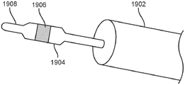
Fig. 13C illustrates the use of an optional coating on the electrode of fig. 13A-13B or any of the electrodes described herein. The electrode 1904 is at least partially disposed in a waveguide 1902, which in turn is movably coupled to an electrosurgical pen or other handle. Portions of the electrode 1906 may be coated with glass and/or may be polished to help reflect light emitted from the waveguide 1902. The light is preferably reflected towards the tip and towards the target work area, and this may help to minimize glare emitted towards the surgeon or other operator. The coated portion 1906 may be selectively disposed over only a portion of the electrode, or it may be disposed over the entire portion of the electrode. The coating can also be on the distal portion 1908 of the portion adjacent the electrode where energy is delivered to the target tissue.
In any embodiment, the LEDs may be disposed in several locations except only at the proximal end of the waveguide. For example, the LED may be located between the proximal and distal ends of the waveguide, or the LED may be located at the distal end. Further, the LEDs may be positioned in any number of orientations relative to the waveguide.
Fig. 14A-14C illustrate alternative embodiments with varying LED positions. Fig. 14A illustrates an energy tip 1406 coupled to a conductor element 1404, the conductor element 1404 extending through a waveguide 1402. A conductor element, such as a wire 1408, is coupled to an electrical connection 1412 on the LED board 1410 and supplies energy, such as RF energy, to the energy tip 1406. A single LED 1414 or an array of LEDs may be disposed on LED board 1410. In this embodiment, the LED board is positioned against the handle and a proximal portion of the waveguide 1402. The parabolic shaped 1416 proximal portion of the waveguide receives light from the LED. Fig. 14B illustrates an end view of the LED board. The LED board is preferably transverse to the longitudinal axis of the waveguide. A single LED may be coaxial with the electrode tip, and the plate may lie in a plane that is generally orthogonal or otherwise transverse to the axis of the waveguide. The board may help dissipate heat into a heat sink, which may surround the waveguide or be butt-coupled to the board. Alternatively, in any embodiment, the waveguide may be coaxial with the electrode.
Fig. 14C illustrates an alternative embodiment in which the LED board 1410 is oriented substantially parallel to the longitudinal axis of the waveguide 1402 and is positioned adjacent the proximal end of the waveguide. The angled parabolic section 1420 of the waveguide receives light from the LED and transmits it distally toward the energy tip 1406. In this embodiment, a conductor element, such as a wire 1422, is coupled to the conductor element 1404 for providing energy to the energy tip 1406. Also, the conductor element 1424 provides power to the LED board. Other locations for the LEDs along the waveguide are contemplated and these embodiments are not intended to be limiting.
Fig. 16A shows an exploded view of another exemplary embodiment of an illumination energy tip 1602, which illumination energy tip 1602 may be coupled to a handpiece such as an electrosurgical pencil (not shown). One advantage of this embodiment is that the lamp and the electrode can be rotated together, thereby ensuring uniform illumination of the target tissue. The illumination energy tip 1602 includes an anodized aluminum shaft 1602, FEP cladding 1604, an LED board 1606, a waveguide half 1608, and an electrode blade 1612. The waveguide may be molded as a single unit, as described elsewhere in this specification, and thus need not have two halves coupled together.
The waveguide halves 1608 may be snap-fit, adhesively bonded, ultrasonically welded together, or otherwise joined together, thereby sandwiching the electrodes between the two waveguide halves. The waveguide halves form a cylindrical shape around the electrode, illuminating around the electrode. The distal portion of the waveguide may include a lens, a plurality of lenslets, or other optical features that help shape the light emitted therefrom. In this embodiment, the optical waveguide has an outer surface that is multi-faceted, forming a polygon that approximates a cylinder. This extraction surface of the waveguide may be flat or curved or even angled or tapered to provide better light directionality, e.g. with respect to divergence of the light. Having multiple facets allows better mixing of light as it passes through the waveguide. The standoffs 1610 in the channels in each half of the waveguide prevent direct contact between the waveguide and the electrode, minimizing contact and subsequent light loss. The channels in each half of the waveguide preferably match the shape of the electrodes located therein.
A cladding layer of FEP is placed over the waveguide and can be heat shrunk down on the two halves, securing the two together. Optionally, other optical coatings may be used in this embodiment or any of the embodiments disclosed herein in combination with or as an alternative to FEP cladding in order to provide a low index material adjacent to the waveguide to prevent or minimize light loss. Also, an air gap may be disposed against the waveguide to help minimize or prevent light loss, as the air gap will provide a lower index of refraction adjacent the waveguide. An outermost aluminum tube 1602 or other thermally conductive material is then disposed over the FEP cladding and helps hold the assembly together and also acts as a heat sink to remove heat build-up. The tube is coupled to the LED core to dissipate heat. The entire assembly can then be coupled to the handpiece, and it can be telescoped within or outside the handpiece. A locking mechanism (not shown), such as a collet or quarter turn lock, may be used to lock the electrode in place once it has been telescoped into the desired position.
Fig. 16B is an end view of illumination energy tip 1602, and fig. 16C is a cross-section taken along line B-B in fig. 16B. Fig. 16C highlights the FEP coated section 1620, as well as the section of the electrode 1622 coupled with the standoffs 1610 to minimize direct contact between the electrode and the waveguide.
In any of the embodiments described herein, the waveguide may also be a lens or have a lens portion for controlling the light delivered from the waveguide. Thus, the waveguide or separate lens, with or without a lens, may be mounted on or otherwise coupled to the LED light source or lighting element used. Optionally, embodiments may thus include an optical element (such as a lens) mounted in front of the illumination element (such as an LED) to direct and shape the light onto the surgical field.
In any of the embodiments described herein, light may be provided to the waveguide by any number of techniques. The illumination element may be disposed in the handle or adjacent a portion of the waveguide. The lighting element may be a single LED or a plurality of LEDs. The LED or LEDs may provide white light or any desired color. For example, when multiple LEDs are used, the LEDs may provide different colors, such as red, green, or blue (RGB), and thus the multiple LEDs may be adjusted to provide light of a desired color input into the waveguide. Thus, waveguides are becoming more important because they will mix different colors of light as the light travels along the length of the waveguide, mixing the different colors of light so that a uniform color of light is delivered to the target. The multiple colors may be used to provide varying shades of white light, or any desired color that assists the surgeon or operator in visualizing and distinguishing various objects (such as tissue) in the surgical field. A filter or coating may be applied to any waveguide to filter out energy at a particular frequency.
Alternatively or in combination, in any of the embodiments described herein, the illumination element may be an optical fiber or a fiber bundle. For example, an optical fiber may input light into the waveguide from an external source such as a xenon lamp. Light from an external source may be transmitted through a fiber optic or fiber optic bundle, through a cable, through the handpiece, and to the proximal end of the waveguide. The optical fiber or fiber bundle may be docked against the waveguide to provide light to the waveguide and subsequently through the waveguide to the surgical field. A lens or other optical element may be used at the distal end of the optical fiber or fiber bundle to input light having desired optical properties to the waveguide. A light source, such as an external light box, may be provided outside the surgical field. Alternatively or in combination, the light source may be a light source in a cable connection. Alternatively or in combination, the light source may be provided in a housing coupled to any part of the cable or device.
In any embodiment, the waveguide may be made of a material having desired optical and mechanical properties. Exemplary materials include acrylic, polycarbonate, cyclic olefin polymer, or cyclic olefin copolymer. In addition, malleable silicones may be used to form the waveguides so that they may be shaped (plastically deformed) into a desired configuration. The moldable silicone may also be coupled directly to the energy tip to provide a waveguide that is coupled to the tip and flexes with the tip when the tip is bent or otherwise flexed. Manufacturers such as Dow Corning and Nusil produce moldable silicone that can be used to form waveguides.
Further, in any of the embodiments described herein, the sensor may be integrated into a waveguide or energy tip. These sensors include, but are not limited to, image sensors, such as CMOS or CCD sensors. The sensors may also be thermal or fiber optic to collect spectroscopic information.
The sensor may be mounted or otherwise integrated into the handle.
The tip may also include means for sensing to actively measure the inductance of tissue in the surgical field. Knowing the inductance of the tissue allows the user to be alerted if the tip is about to cut through or otherwise damage a critical structure. It is also contemplated to integrate fiber sensing into the tip to measure the temperature spread of the tissue and to perform spectroscopic analysis of the tissue. Other embodiments may include an imaging element, such as a camera, which may be mounted on the pen handle or integrated into the sleeve or other portion of the electrosurgical tip. Any of these features may be used or combined with the illumination tip. Fig. 16D shows an exemplary embodiment of energy tip 1602 with sensor 1624 integrated therein. Sensor 1624 may be, for example, an optical sensor, a thermal sensor, an inductive sensor, or a spectroscopic sensor. Only one sensor is represented herein, however, it is understood that any number or combination of sensors may be integrated into one or more of the energy tip, waveguide, handle, or combinations thereof.
Other embodiments may include a handle having ventilation features that allow air to circulate through the handle, thereby facilitating cooling of the handle and waveguide.
Fig. 17A-17B illustrate the use of alternative batteries or other power sources to provide energy to the lighting elements. This optional feature may be used in any of the embodiments described herein.
Fig. 17A illustrates an electrosurgical instrument having a pen or handle 1702 with the pen or handle 1702 having an electrode 1704 with or without an illumination element coupled to a distal portion of the handle. An instrument cable 1706 is fixedly or releasably coupled to the proximal portion of the handle, and the opposite end of the cable 1706 includes a plug or adaptor or connector 1708 having electrical connector pins 1701 for coupling with an electrosurgical generator or any other external case (e.g., controller, light source, power source, etc.).
Figure 17B highlights features of the plug 1708, the plug 1708 including a recessed region 1714 sized and shaped to receive a battery 1712 or other power source (e.g., a capacitor) that may be used to provide power to the lighting elements (e.g., LEDs). The contacts on the battery 1716 engage the corresponding contacts 1718 in the recessed region 1714 to complete the electrical circuit. The battery may be a disposable battery or a rechargeable battery. This feature allows the batteries to be easily replaced during surgery without disturbing the surgeon who may be using the electrosurgical instrument. Also, this portion of the plug is typically outside the sterile field, further facilitating its replacement. The end of the cable 1706 coupled to the plug 1708 may be fixedly or releasably attached to the plug. Thus, if desired, the plug can be easily interchanged with a new plug having a new battery, thereby further facilitating this process.
18A-18E illustrate another exemplary embodiment of an illuminated electrosurgical tip 1802. Those skilled in the art will appreciate that any feature described in this embodiment may be used in combination with or instead of a feature in any of the other embodiments described herein.
Fig. 18A illustrates an illuminated electrosurgical tip 1802 having an electrode tip 1804 coupled to a waveguide 1808 and having an illuminating element 1828 on a circuit board 1826 adjacent a proximal end of the waveguide. The electrode tip 1804 has a distal rounded tip 1805, and may have similar insulative and non-insulative regions as previously described in other embodiments to control the delivery of energy to the target tissue. The electrode tip 1804 flares outward 1816 (or tapers distally) into a flat planar section, which in turn terminates and only the elongated arm 1822 extends proximally. The elongated arm 1822 serves as a conductor to deliver energy from an energy source to the electrode tip. The waveguide has a narrow vertically oriented slot 1818 which in turn transitions into an elongate channel 1820 for receiving the flat planar section and the elongate arm. A rounded protrusion 1832 (best seen in fig. 18B) extends from the elongate arm and is received in a correspondingly shaped recess in the waveguide and prevents axial movement of the electrode relative to the waveguide.
The waveguide is preferably a non-fiber optic waveguide formed as a single unitary piece, such as by injection molding. The distal portion of the waveguide includes a plurality of microstructures 1812 for controlling the light extracted therefrom and ensuring that the extracted light has desired optical properties (e.g., divergence, intensity, etc.). Rims 1814 are formed around the microstructures, and rims 1814 serve as surfaces against which the inner surface of the metal tube can rest. The metal tube has been previously described above and acts as a heat sink. The body of the waveguide is preferably multi-faceted, with a series of external planar surfaces forming a polygonal outer surface. This aids in light transmission through the waveguide because the multiple surfaces allow light to bounce off the multiple surfaces, providing more mixing of the light.
The proximal end of the waveguide is preferably parabolic shaped to help direct light from the illumination element 1828, which is preferably an LED, into the waveguide. The parabola is centered over the LED. The arm 1820 is offset from the central axis of the waveguide and is received in a slot 1830 in the circuit board 1826.
Fig. 18B illustrates an exploded view of the illumination electrode tip 1802, while fig. 18D illustrates an exploded side view of the illumination electrode tip 1802.
Fig. 18E illustrates a perspective view of electrode 1804, and fig. 18F illustrates a perspective view of fig. 18F.
While preferred embodiments of the present invention have been shown and described herein, it will be obvious to those skilled in the art that such embodiments are provided by way of example only. Numerous variations, changes, and substitutions will now occur to those skilled in the art without departing from the invention. It should be understood that various alternatives to the embodiments of the invention described herein may be employed in practicing the invention. It is intended that the following claims define the scope of the invention and that methods and structures within the scope of these claims and their equivalents be covered thereby.
Claims (42)
1. An illuminated electrosurgical instrument, the instrument comprising:
a handle having a proximal end and a distal end;
an optical waveguide coupled to the handle, wherein the optical waveguide has a proximal end and a distal end, the optical waveguide extending from the distal end of the handle in a distal direction, the optical waveguide being adjustably coupled to the handle such that the optical waveguide is movable along a longitudinal axis such that a distance between the distal end of the optical waveguide and the proximal end of the handle is adjustable without decoupling the optical waveguide from the handle;
a locking mechanism coupled to the optical waveguide, the locking mechanism for selectively locking the optical waveguide in a plurality of positions along the longitudinal axis relative to the proximal end of the handle, wherein the locking mechanism extends circumferentially around the optical waveguide, the locking mechanism having an unlocked position in which the optical waveguide is movable along the longitudinal axis so as to extend or retract through an inner diameter of the locking mechanism, and a locked position in which the locking mechanism clamps around the optical waveguide and moves along the longitudinal axis against the optical waveguide, the locking mechanism comprising a collet, a twist lock, a right angle twist lock, or a protrusion-recess locking pair; and
an electrosurgical tip coupled to the optical waveguide.
2. The illuminated electrosurgical instrument as recited in claim 1, wherein the electrosurgical tip is removably coupled with the optical waveguide.
3. The illuminated electrosurgical instrument as recited in claim 1, wherein the electrosurgical tip is integral with the optical waveguide.
4. The illuminated electrosurgical instrument as recited in claim 1 wherein the electrosurgical tip is flat, curved, tapered, or a combination thereof.
5. The illuminated electrosurgical instrument as recited in claim 1 wherein the electrosurgical tip is a flat planar blade.
6. The illuminated electrosurgical instrument as recited in claim 1 wherein the electrosurgical tip comprises an electrode.
7. The illuminated electrosurgical instrument as recited in claim 1, wherein the optical waveguide comprises one or more of: acrylic, polycarbonate, cyclic olefin polymer, cyclic olefin copolymer, or ductile silicone.
8. The illuminated electrosurgical instrument as recited in claim 1, wherein the optical waveguide is cylindrical, square, rectangular, elliptical, oval, triangular, or polygonal.
9. The illuminated electrosurgical instrument as recited in claim 1, wherein the optical waveguide is tapered at a proximal end such that a cross-sectional area of the proximal end of the optical waveguide is less than a cross-sectional area of the distal end of the optical waveguide.
10. The illuminated electrosurgical instrument as recited in claim 1, wherein the optical waveguide comprises an extraction surface that is flat, curved, angled, tapered, or a combination thereof.
11. The illuminated electrosurgical instrument as recited in claim 1 wherein the optical waveguide is a plurality of flat planar facets forming a polygonal outer surface.
12. The illuminated electrosurgical instrument as recited in claim 1, wherein the optical waveguide is formed by adhesive bonding, ultrasonic welding, molding, injection molding, heat shrinking, or snap fitting.
13. The illuminated electrosurgical instrument as recited in claim 1, wherein the optical waveguide further comprises one or more of: a lens, a hollow reflector, a gradient lens, a lenslet, a plurality of lenslets, a filter, or a coating for desired optical properties.
14. The illuminated electrosurgical instrument as recited in claim 1, wherein said optical waveguide includes one or more smoke evacuation channels extending axially through said optical waveguide to a proximal end thereof.
15. The illuminated electrosurgical instrument as recited in claim 1, further comprising an illumination element coupled to the optical waveguide.
16. The illuminated electrosurgical instrument as recited in claim 15 wherein the illumination element comprises a Light Emitting Diode (LED), a plurality of LEDs, a xenon lamp, or any combination thereof.
17. The illuminated electrosurgical instrument as recited in claim 16, wherein the LED or LEDs comprise parabolic LEDs.
18. The illuminated electrosurgical instrument as recited in claim 15 wherein said illumination element is disposed on said handle.
19. The illuminated electrosurgical instrument as recited in claim 15 wherein said illumination element is external to said handle.
20. The illuminated electrosurgical instrument as recited in claim 1 further comprising a conductive element disposed on the optical waveguide and coupled to the electrosurgical tip.
21. The illuminated electrosurgical instrument as recited in claim 1, wherein the optical waveguide has a central cavity that at least partially houses a conductive element that fully occupies the central cavity, and wherein the conductive element is selected from the group consisting of a wire, a proximal portion of the electrosurgical tip, a shaft, and a tube.
22. The illuminated electrosurgical instrument as recited in claim 1, further comprising a conductive element disposed in or through the optical waveguide and coupled to the electrosurgical tip.
23. The illuminated electrosurgical instrument as recited in claim 1, wherein the optical waveguide includes a central channel extending therethrough, and wherein the central channel is for venting smoke.
24. The illuminated electrosurgical instrument as recited in claim 1, wherein the optical waveguide further comprises a central cavity that at least partially houses the proximal portion of the electrosurgical tip such that the proximal portion of the electrosurgical tip fully occupies the central cavity.
25. The illuminated electrosurgical instrument as recited in claim 24, wherein the optical waveguide comprises a solid rod.
26. The illuminated electrosurgical instrument as recited in claim 1, further comprising one or more sensors selected from the group consisting of image sensors, thermal sensors, inductive sensors, and spectroscopic sensors.
27. The illuminated electrosurgical instrument as recited in claim 1, further comprising an insulator, wherein the insulator is directly coupled to one or more of: an outer surface of the optical waveguide, a central channel of the optical waveguide, an outer surface of a conducting element, the electrosurgical tip, an illuminating element, or one or more portions of the electrosurgical tip.
28. The illuminated electrosurgical instrument as recited in claim 27, wherein the insulator is one or more of: coating, cladding, heat shrink tubing, fluorinated ethylene propylene, glass, polytetrafluoroethylene, aluminum tubing, air gaps, or multiple air gaps.
29. The illuminated electrosurgical instrument as recited in claim 1 wherein said handle includes a ventilation feature for added air circulation.
30. The illuminated electrosurgical instrument as recited in claim 1, further comprising an illumination element configured to generate light and coupled to a proximal end of the optical waveguide, wherein the illumination element and the electrosurgical tip are configured to move with the optical waveguide as the optical waveguide is adjusted relative to the handle.
31. An illuminated electrosurgical instrument, the instrument comprising:
a handle having a proximal end and a distal end;
a non-fiber optic waveguide having a proximal end and a distal end, wherein the optical waveguide is adjustably coupled to the handle such that the optical waveguide is movable along a longitudinal axis such that a distance between the distal end of the optical waveguide and the proximal end of the handle is adjustable without decoupling the optical waveguide from the handle, wherein the optical waveguide is telescopically arranged with respect to the handle such that (i) a portion of the optical waveguide telescopes out of the handle when the optical waveguide is distally adjusted relative to the entirety of the handle, and (ii) a portion of the optical waveguide telescopes into the handle when the optical waveguide is proximally adjusted relative to the entirety of the handle;
an electrosurgical tip coupled to the optical waveguide and comprising an electrode blade, wherein a distal portion of the electrode blade is covered by an insulating coating; and
an illumination element configured to generate light and coupled to a proximal end of the non-fiber optic waveguide;
wherein the illumination element and the electrosurgical tip are configured to move with the non-fiber optic waveguide as the non-fiber optic waveguide moves bodily relative to the handle along the longitudinal axis.
32. The illuminated electrosurgical instrument as recited in claim 31, wherein the optical waveguide is independently movable relative to the electrosurgical tip.
33. The illuminated electrosurgical instrument as recited in claim 31, wherein the electrosurgical tip is coupled to the optical waveguide such that movement of the optical waveguide relative to the handle causes corresponding movement of the electrosurgical tip relative to the handle.
34. The illuminated electrosurgical instrument as recited in claim 31, wherein the optical waveguide and the electrosurgical tip are configured to rotate together relative to the handle.
35. The illuminated electrosurgical instrument as recited in claim 31, further comprising a locking mechanism coupled to the optical waveguide and configured to selectively lock the optical waveguide in a plurality of positions relative to the proximal end of the handle.
36. The illuminated electrosurgical instrument as recited in claim 31, wherein the electrosurgical tip is removably coupled with the optical waveguide.
37. An illuminated electrosurgical instrument, the instrument comprising:
a handle having a proximal end and a distal end;
a non-fiber optic waveguide having a proximal end and a distal end, wherein the optical waveguide is adjustably coupled to the handle such that the optical waveguide is movable along a longitudinal axis such that a distance between the distal end of the optical waveguide and the proximal end of the handle is adjustable without decoupling the optical waveguide from the handle, wherein the optical waveguide is telescopically arranged with respect to the handle such that (i) a portion of the optical waveguide telescopes out of the handle when the optical waveguide is distally adjusted relative to the entirety of the handle, and (ii) a portion of the optical waveguide telescopes into the handle when the optical waveguide is proximally adjusted relative to the entirety of the handle;
a locking mechanism coupled to the optical waveguide for selectively locking the optical waveguide in a plurality of positions along the longitudinal axis relative to the proximal end of the handle; and
an electrosurgical tip coupled to the optical waveguide and comprising an electrode blade, wherein a distal portion of the electrode blade is covered by an insulating coating, wherein the electrosurgical tip is fixedly coupled to the optical waveguide such that the electrosurgical tip moves with the optical waveguide relative to the handle, and
wherein the optical waveguide and the electrosurgical tip are configured to rotate together relative to the handle without decoupling the optical waveguide and the electrosurgical tip from the handle.
38. The illuminated electrosurgical instrument as recited in claim 37, wherein the optical waveguide comprises first and second halves coupled to one another with the electrosurgical tip positioned therebetween.
39. The illuminated electrosurgical instrument as recited in claim 38, wherein the first and second halves of the optical waveguide each include a channel;
the optical waveguide includes a plurality of standoff nuts located in a channel of a first half and a channel of a second half; and
the plurality of standoff posts of the optical waveguide prevent the electrosurgical tip from making direct contact with the channel of the optical waveguide.
40. The illuminated electrosurgical instrument as in claim 37, further comprising a light source coupled to the proximal end of the optical waveguide;
wherein the electrosurgical tip comprises a proximal portion having an angled section such that the proximal portion of the electrosurgical tip extends proximally of the electrosurgical tip at an off-center position in the handle.
41. The illuminated electrosurgical instrument as recited in claim 37, wherein the optical waveguide includes a slit located on an outer surface of the optical waveguide; and
the slot on the outer surface of the optical waveguide receives the arm of the electrosurgical tip.
42. The illuminated electrosurgical instrument as recited in claim 41, wherein the electrosurgical tip includes a protrusion that is received within a recess of the optical waveguide to inhibit axial movement of the electrosurgical tip relative to the optical waveguide.
Priority Applications (1)
| Application Number | Priority Date | Filing Date | Title |
|---|---|---|---|
| CN202211003814.1A CN115568937A (en) | 2014-12-08 | 2015-12-08 | Method and apparatus for electrosurgical illumination and sensing |
Applications Claiming Priority (7)
| Application Number | Priority Date | Filing Date | Title |
|---|---|---|---|
| US201462089023P | 2014-12-08 | 2014-12-08 | |
| US62/089,023 | 2014-12-08 | ||
| US201562136335P | 2015-03-20 | 2015-03-20 | |
| US62/136,335 | 2015-03-20 | ||
| US201562212516P | 2015-08-31 | 2015-08-31 | |
| US62/212,516 | 2015-08-31 | ||
| PCT/US2015/064553 WO2016094443A1 (en) | 2014-12-08 | 2015-12-08 | Methods and apparatus for electrosurgical illumination and sensing |
Related Child Applications (1)
| Application Number | Title | Priority Date | Filing Date |
|---|---|---|---|
| CN202211003814.1A Division CN115568937A (en) | 2014-12-08 | 2015-12-08 | Method and apparatus for electrosurgical illumination and sensing |
Publications (2)
| Publication Number | Publication Date |
|---|---|
| CN106999716A CN106999716A (en) | 2017-08-01 |
| CN106999716B true CN106999716B (en) | 2022-09-06 |
Family
ID=56093216
Family Applications (2)
| Application Number | Title | Priority Date | Filing Date |
|---|---|---|---|
| CN202211003814.1A Pending CN115568937A (en) | 2014-12-08 | 2015-12-08 | Method and apparatus for electrosurgical illumination and sensing |
| CN201580066743.1A Active CN106999716B (en) | 2014-12-08 | 2015-12-08 | Method and apparatus for electrosurgical illumination and sensing |
Family Applications Before (1)
| Application Number | Title | Priority Date | Filing Date |
|---|---|---|---|
| CN202211003814.1A Pending CN115568937A (en) | 2014-12-08 | 2015-12-08 | Method and apparatus for electrosurgical illumination and sensing |
Country Status (8)
| Country | Link |
|---|---|
| US (2) | US10456190B2 (en) |
| EP (1) | EP3229899A4 (en) |
| JP (4) | JP6674952B2 (en) |
| KR (1) | KR102475202B1 (en) |
| CN (2) | CN115568937A (en) |
| AU (3) | AU2015360712B2 (en) |
| CA (1) | CA2965990A1 (en) |
| WO (1) | WO2016094443A1 (en) |
Families Citing this family (33)
| Publication number | Priority date | Publication date | Assignee | Title |
|---|---|---|---|---|
| AU2020257128B2 (en) * | 2014-12-08 | 2022-05-12 | Invuity, Inc. | Methods and apparatus for electrosurgical illumination |
| US10420538B2 (en) | 2015-02-05 | 2019-09-24 | Obp Medical Corporation | Illuminated surgical retractor |
| US10939899B2 (en) | 2015-06-03 | 2021-03-09 | Obp Medical Corporation | End cap assembly for retractor and other medical devices |
| CN209199686U (en) * | 2016-03-10 | 2019-08-02 | 西门子股份公司 | High-tension apparatus and high-pressure installation with the high voltage component being electrically isolated with high-tension apparatus |
| US10722621B2 (en) | 2016-07-11 | 2020-07-28 | Obp Medical Corporation | Illuminated suction device |
| CA3036209A1 (en) * | 2016-09-16 | 2018-03-22 | Invuity, Inc. | Methods and apparatus for electrosurgical illumination |
| CN109890305B (en) * | 2016-10-24 | 2022-04-26 | 因维蒂有限公司 | Lighting element |
| US10390903B2 (en) * | 2016-10-24 | 2019-08-27 | Steven Warnock | Illuminated apparatus with telescoping for electrocautery devices and method of use |
| WO2018081820A1 (en) * | 2016-10-31 | 2018-05-03 | U.S. Patent Innovations Llc | Attachment for electrosurgical system |
| US10194975B1 (en) * | 2017-07-11 | 2019-02-05 | Medtronic Advanced Energy, Llc | Illuminated and isolated electrosurgical apparatus |
| US10687793B2 (en) | 2017-07-18 | 2020-06-23 | Obp Medical Corporation | Minimally invasive no touch (MINT) procedure for harvesting the great saphenous vein (GSV) and venous hydrodissector and retractor for use during the MINT procedure |
| US11207126B2 (en) * | 2017-07-21 | 2021-12-28 | Medtronic Advanced Energy Llc | Smoke evacuation electrosurgical instrument |
| US11871980B2 (en) | 2017-08-10 | 2024-01-16 | Medtronic Advanced Energy Llc | Electrosurgical system with electrode assembly and accessory charge circuit |
| US10610257B2 (en) | 2018-02-17 | 2020-04-07 | Nano 2.0 Business Press, Llc | Structural element with bayonet having a universal blade fitting with electrical source pod and terminal configuration |
| US10799229B2 (en) | 2018-02-20 | 2020-10-13 | Obp Medical Corporation | Illuminated medical devices |
| US20190321093A1 (en) * | 2018-04-20 | 2019-10-24 | Medtronic Advanced Energy Llc | Illuminated electrosurgical devices, systems and methods |
| US11717373B2 (en) | 2018-06-19 | 2023-08-08 | Medtronic Advanced Energy Llc | Illuminated electrosurgical devices, systems and methods |
| CN108969092A (en) * | 2018-07-03 | 2018-12-11 | 杭州埃杜医疗科技有限公司 | A kind of low temperature radio frequency plasma surgery systems |
| CN108742833B (en) * | 2018-08-13 | 2024-02-13 | 浙江迈德实达医疗科技有限公司 | Smoking high-frequency surgical knife with illumination and lockable telescopic length |
| CN112804957A (en) * | 2018-08-27 | 2021-05-14 | 因维蒂有限公司 | Electrosurgical device, method of manufacturing an electrosurgical device, and method of using an electrosurgical device |
| US11298185B2 (en) * | 2018-09-07 | 2022-04-12 | Leoni Kabel Gmbh | Optical fiber with modified distal end |
| US10716642B1 (en) * | 2019-07-23 | 2020-07-21 | Pathy Medical, Llc | Lighting device for handheld surgical instrument with smoke evacuation system |
| CA3146359A1 (en) * | 2019-11-12 | 2021-05-20 | Stryker European Operations Limited | Electrosurgical device with illumination and smoke evacuation features |
| US20210153731A1 (en) * | 2019-11-26 | 2021-05-27 | Gyrus Acmi, Inc. D/B/A Olympus Surgical Technologies America | Surgical instruments with integrated lighting systems |
| US11819244B2 (en) | 2019-11-27 | 2023-11-21 | Gyrus Acmi, Inc. | Surgical device for treatment of endometriosis |
| US20210212748A1 (en) * | 2020-01-10 | 2021-07-15 | Pathy Medical, Llc | Lighted electrocautery blade assembly for handheld electrosurgical instrument |
| US10959609B1 (en) | 2020-01-31 | 2021-03-30 | Obp Medical Corporation | Illuminated suction device |
| US10966702B1 (en) | 2020-02-25 | 2021-04-06 | Obp Medical Corporation | Illuminated dual-blade retractor |
| WO2022053867A2 (en) * | 2020-09-09 | 2022-03-17 | Stryker European Operations Limited | Electrosurgical devices, methods of use, and methods of manufacture |
| WO2023057817A1 (en) * | 2021-10-05 | 2023-04-13 | Stryker European Operations Limited | Electrosurgical devices having embedded sensors, methods of use, and methods of manufacture |
| CN114191721B (en) * | 2021-12-24 | 2022-12-09 | 北京中成康富科技股份有限公司 | Irradiation head walking device of millimeter wave treatment bed body |
| WO2023223096A1 (en) * | 2022-05-16 | 2023-11-23 | Stryker European Operations Limited | Electrosurgical tools, methods of use, and methods of manufacture |
| CN115040234B (en) * | 2022-05-20 | 2023-02-10 | 东悦医疗器械(武汉)有限公司 | Ablation electrode with illumination function |
Citations (3)
| Publication number | Priority date | Publication date | Assignee | Title |
|---|---|---|---|---|
| US4688569A (en) * | 1986-06-09 | 1987-08-25 | Medi-Tech, Inc. | Finger actuated surgical electrode holder |
| WO2006009705A2 (en) * | 2004-06-17 | 2006-01-26 | Jnj Technology Holdings, L.L.C. | Ablation apparatus and system to limit nerve conduction |
| CN102697529A (en) * | 2012-06-28 | 2012-10-03 | 天津正展昌电子科技有限公司 | Minimally invasive instrument |
Family Cites Families (45)
| Publication number | Priority date | Publication date | Assignee | Title |
|---|---|---|---|---|
| US3677262A (en) | 1970-07-23 | 1972-07-18 | Henry J Zukowski | Surgical instrument illuminating endotracheal tube inserter |
| US4562838A (en) * | 1981-01-23 | 1986-01-07 | Walker William S | Electrosurgery instrument |
| JPS6450006A (en) * | 1987-08-21 | 1989-02-27 | Matsushita Electric Ind Co Ltd | Optical fiber cable |
| US5221279A (en) * | 1990-10-12 | 1993-06-22 | Surgical Laser Technologies, Inc. | Adjustable touch control handpiece |
| US5456689A (en) | 1993-10-13 | 1995-10-10 | Arnold J. Kresch | Method and device for tissue resection |
| US20020058931A1 (en) * | 1995-06-27 | 2002-05-16 | Jeffrey R. Parker | Light delivery system and applications thereof |
| US5836909A (en) | 1996-09-13 | 1998-11-17 | Cosmescu; Ioan | Automatic fluid control system for use in open and laparoscopic laser surgery and electrosurgery and method therefor |
| US6591049B2 (en) * | 1997-07-02 | 2003-07-08 | Lumitex, Inc. | Light delivery systems and applications thereof |
| US6610057B1 (en) * | 2001-03-27 | 2003-08-26 | Alan G. Ellman | Electrosurgical blade electrode |
| US6550926B2 (en) | 2001-03-30 | 2003-04-22 | Leon Berger | Telescoping probe with interchangeable mirrors and light emitting diodes including ultraviolet |
| DE10117347B4 (en) * | 2001-04-06 | 2006-04-13 | W&H Dentalwerk Bürmoos Gesellschaft m.b.H. | Laser treatment devices with lighting system |
| US6744955B2 (en) * | 2001-06-29 | 2004-06-01 | Alcatel | Buffer tube having a high fiber count ribbon stack packaging configuration and corner cushions |
| US20070049927A1 (en) * | 2005-08-31 | 2007-03-01 | Saltzman Darin J | Electrosurgical pencil with a light |
| US8409088B2 (en) | 2006-01-18 | 2013-04-02 | Invuity, Inc. | Retractor illumination system |
| US9907621B2 (en) * | 2008-11-14 | 2018-03-06 | Prash Jayaraj | Surgical pencil |
| US8690872B2 (en) | 2008-11-14 | 2014-04-08 | Prash Jayaraj | Surgical pencil enabling suction |
| US9808306B2 (en) * | 2008-12-09 | 2017-11-07 | Carl Balog | Fume evacuating electrosurgical scalpel |
| US8287534B2 (en) | 2008-12-09 | 2012-10-16 | Carl Balog | Light emitting electrosurgical scalpel |
| CN102378602A (en) * | 2009-04-01 | 2012-03-14 | 赛诺龙医疗公司 | A method and apparatus for liposuction |
| US8882768B2 (en) | 2009-04-24 | 2014-11-11 | Megadyne Medical Products, Inc. | Hand piece with adjustable utility conduit |
| US8882767B2 (en) | 2009-04-24 | 2014-11-11 | Megadyne Medical Products, Inc. | Electrosurgical instrument with adjustable utility conduit |
| TW201108985A (en) | 2009-09-09 | 2011-03-16 | Ming-Huei Cheng | Coagulation device with combination of suction and light emission |
| US8795162B2 (en) * | 2009-11-10 | 2014-08-05 | Invuity, Inc. | Illuminated suction apparatus |
| US9289261B2 (en) | 2010-02-04 | 2016-03-22 | Buffalo Filter Llc | Electrosurgical device with vacuum port |
| DE102010015068A1 (en) * | 2010-04-15 | 2011-10-20 | Paul Voinea | fiber optic system |
| US9028088B2 (en) * | 2010-09-30 | 2015-05-12 | Black & Decker Inc. | Lighted power tool |
| KR102161945B1 (en) * | 2010-12-16 | 2020-10-21 | 인뷰이티 인코퍼레이티드 | Illuminated suction apparatus |
| CN102670299B (en) | 2011-02-28 | 2016-05-11 | 罗伯特·L·布罗姆利 | A kind of improved hand-held high-frequency electrotome pen |
| US8986292B2 (en) * | 2011-04-13 | 2015-03-24 | St. Jude Medical, Inc. | Optical feedback RF ablator and ablator tip |
| US10595934B2 (en) * | 2011-05-02 | 2020-03-24 | I.C. Medical, Inc. | Electrosurgical unit pencil apparatus and shroud having directed illumination |
| EP2704619B1 (en) * | 2011-05-06 | 2017-11-08 | Ioan Cosmescu | Light attachment device for electrosurgical pencil and for electrosurgical pencil attachments |
| EP2726006A1 (en) * | 2011-06-28 | 2014-05-07 | SafeAir AG | An elongated electrosurgical instrument, a suction tip for the electrosurgical instrument and method of adjusting the axial position of the suction tip on the electrosurgical instrument |
| JP6224593B2 (en) | 2011-09-23 | 2017-11-01 | インブイティ・インコーポレイテッド | Illuminated modular soft tissue retractor |
| IL219885A0 (en) * | 2012-05-20 | 2012-07-31 | Scalpal Llc | Surgical instrument suitable for use in deep surgery |
| US20130343046A1 (en) * | 2012-06-22 | 2013-12-26 | Chang Ching TSAI | LED Light Tube |
| KR102176485B1 (en) * | 2012-09-24 | 2020-11-09 | 인뷰이티 인코퍼레이티드 | Methods and apparatus for controlling optical properties of light |
| JP6417331B2 (en) * | 2012-12-12 | 2018-11-07 | インブイティ・インコーポレイテッド | Irradiation suction device |
| US8875202B2 (en) * | 2013-03-14 | 2014-10-28 | General Instrument Corporation | Processing path signatures for processing elements in encoded video |
| US9259260B2 (en) | 2013-03-14 | 2016-02-16 | Megadyne Medical Products, Inc. | Fluid evacuation device |
| US9375253B2 (en) | 2013-03-14 | 2016-06-28 | Megadyne Medical Products, Inc. | Electrosurgical instrument |
| CA3169888A1 (en) | 2013-04-01 | 2014-10-09 | Vinod V. Pathy | Lighting device |
| WO2015085108A1 (en) | 2013-12-04 | 2015-06-11 | Fleenor Richard P | Hand-held smoke evacuation instrument |
| USD761962S1 (en) | 2015-06-03 | 2016-07-19 | Richard P. Fleenor | Light tunnel for electrosurgical pencil |
| US10561459B2 (en) | 2015-06-03 | 2020-02-18 | Richard P. Fleenor | Multi-feature electrosurgical instrument |
| US10194975B1 (en) * | 2017-07-11 | 2019-02-05 | Medtronic Advanced Energy, Llc | Illuminated and isolated electrosurgical apparatus |
-
2015
- 2015-12-08 CN CN202211003814.1A patent/CN115568937A/en active Pending
- 2015-12-08 WO PCT/US2015/064553 patent/WO2016094443A1/en active Application Filing
- 2015-12-08 US US14/962,942 patent/US10456190B2/en active Active
- 2015-12-08 CA CA2965990A patent/CA2965990A1/en active Pending
- 2015-12-08 CN CN201580066743.1A patent/CN106999716B/en active Active
- 2015-12-08 KR KR1020177014799A patent/KR102475202B1/en active IP Right Grant
- 2015-12-08 JP JP2017530132A patent/JP6674952B2/en active Active
- 2015-12-08 AU AU2015360712A patent/AU2015360712B2/en active Active
- 2015-12-08 EP EP15866893.9A patent/EP3229899A4/en active Pending
-
2019
- 2019-10-11 US US16/600,224 patent/US20200038095A1/en active Pending
-
2020
- 2020-03-09 JP JP2020039845A patent/JP7002581B2/en active Active
- 2020-08-18 AU AU2020220081A patent/AU2020220081B2/en active Active
-
2021
- 2021-12-27 JP JP2021212185A patent/JP7366114B2/en active Active
-
2023
- 2023-03-15 AU AU2023201617A patent/AU2023201617A1/en active Pending
- 2023-10-10 JP JP2023175120A patent/JP2023179642A/en active Pending
Patent Citations (3)
| Publication number | Priority date | Publication date | Assignee | Title |
|---|---|---|---|---|
| US4688569A (en) * | 1986-06-09 | 1987-08-25 | Medi-Tech, Inc. | Finger actuated surgical electrode holder |
| WO2006009705A2 (en) * | 2004-06-17 | 2006-01-26 | Jnj Technology Holdings, L.L.C. | Ablation apparatus and system to limit nerve conduction |
| CN102697529A (en) * | 2012-06-28 | 2012-10-03 | 天津正展昌电子科技有限公司 | Minimally invasive instrument |
Also Published As
| Publication number | Publication date |
|---|---|
| JP2018501848A (en) | 2018-01-25 |
| KR20170094172A (en) | 2017-08-17 |
| AU2015360712A1 (en) | 2017-05-18 |
| WO2016094443A1 (en) | 2016-06-16 |
| CN106999716A (en) | 2017-08-01 |
| US10456190B2 (en) | 2019-10-29 |
| AU2020220081B2 (en) | 2022-12-15 |
| CA2965990A1 (en) | 2016-06-16 |
| JP2022043235A (en) | 2022-03-15 |
| JP2023179642A (en) | 2023-12-19 |
| JP7366114B2 (en) | 2023-10-20 |
| US20200038095A1 (en) | 2020-02-06 |
| AU2023201617A1 (en) | 2023-04-13 |
| EP3229899A4 (en) | 2018-07-04 |
| US20160157920A1 (en) | 2016-06-09 |
| JP7002581B2 (en) | 2022-01-20 |
| CN115568937A (en) | 2023-01-06 |
| AU2020220081A1 (en) | 2020-09-03 |
| AU2015360712B2 (en) | 2020-05-21 |
| JP2020096987A (en) | 2020-06-25 |
| EP3229899A1 (en) | 2017-10-18 |
| KR102475202B1 (en) | 2022-12-07 |
| JP6674952B2 (en) | 2020-04-01 |
Similar Documents
| Publication | Publication Date | Title |
|---|---|---|
| CN106999716B (en) | Method and apparatus for electrosurgical illumination and sensing | |
| US20220008116A1 (en) | Methods and Apparatus for Electrosurgical Illumination | |
| US9308054B2 (en) | Illuminated suction apparatus | |
| EP3000381A1 (en) | Illuminated suction apparatus | |
| EP3473160B1 (en) | Illuminated suction apparatus | |
| AU2020257128B2 (en) | Methods and apparatus for electrosurgical illumination |
Legal Events
| Date | Code | Title | Description |
|---|---|---|---|
| PB01 | Publication | ||
| PB01 | Publication | ||
| SE01 | Entry into force of request for substantive examination | ||
| SE01 | Entry into force of request for substantive examination | ||
| REG | Reference to a national code |
Ref country code: HK Ref legal event code: DE Ref document number: 1234688 Country of ref document: HK |
|
| GR01 | Patent grant | ||
| GR01 | Patent grant |