CN106998656B - Portable electric tool, in particular electric pruning shears with a heat sink - Google Patents
Portable electric tool, in particular electric pruning shears with a heat sink Download PDFInfo
- Publication number
- CN106998656B CN106998656B CN201580063718.8A CN201580063718A CN106998656B CN 106998656 B CN106998656 B CN 106998656B CN 201580063718 A CN201580063718 A CN 201580063718A CN 106998656 B CN106998656 B CN 106998656B
- Authority
- CN
- China
- Prior art keywords
- power tool
- portable power
- housing
- motor
- intermediate housing
- Prior art date
- Legal status (The legal status is an assumption and is not a legal conclusion. Google has not performed a legal analysis and makes no representation as to the accuracy of the status listed.)
- Active
Links
Images

Classifications
-
- A—HUMAN NECESSITIES
- A01—AGRICULTURE; FORESTRY; ANIMAL HUSBANDRY; HUNTING; TRAPPING; FISHING
- A01G—HORTICULTURE; CULTIVATION OF VEGETABLES, FLOWERS, RICE, FRUIT, VINES, HOPS OR SEAWEED; FORESTRY; WATERING
- A01G3/00—Cutting implements specially adapted for horticultural purposes; Delimbing standing trees
- A01G3/02—Secateurs; Flower or fruit shears
- A01G3/033—Secateurs; Flower or fruit shears having motor-driven blades
- A01G3/037—Secateurs; Flower or fruit shears having motor-driven blades the driving means being an electric motor
-
- A—HUMAN NECESSITIES
- A01—AGRICULTURE; FORESTRY; ANIMAL HUSBANDRY; HUNTING; TRAPPING; FISHING
- A01D—HARVESTING; MOWING
- A01D46/00—Picking of fruits, vegetables, hops, or the like; Devices for shaking trees or shrubs
- A01D46/24—Devices for picking apples or like fruit
- A01D46/253—Portable motorised fruit pickers
-
- B—PERFORMING OPERATIONS; TRANSPORTING
- B26—HAND CUTTING TOOLS; CUTTING; SEVERING
- B26B—HAND-HELD CUTTING TOOLS NOT OTHERWISE PROVIDED FOR
- B26B15/00—Hand-held shears with motor-driven blades
-
- A—HUMAN NECESSITIES
- A01—AGRICULTURE; FORESTRY; ANIMAL HUSBANDRY; HUNTING; TRAPPING; FISHING
- A01G—HORTICULTURE; CULTIVATION OF VEGETABLES, FLOWERS, RICE, FRUIT, VINES, HOPS OR SEAWEED; FORESTRY; WATERING
- A01G3/00—Cutting implements specially adapted for horticultural purposes; Delimbing standing trees
- A01G3/02—Secateurs; Flower or fruit shears
- A01G3/033—Secateurs; Flower or fruit shears having motor-driven blades
-
- F—MECHANICAL ENGINEERING; LIGHTING; HEATING; WEAPONS; BLASTING
- F28—HEAT EXCHANGE IN GENERAL
- F28D—HEAT-EXCHANGE APPARATUS, NOT PROVIDED FOR IN ANOTHER SUBCLASS, IN WHICH THE HEAT-EXCHANGE MEDIA DO NOT COME INTO DIRECT CONTACT
- F28D21/00—Heat-exchange apparatus not covered by any of the groups F28D1/00 - F28D20/00
- F28D2021/0019—Other heat exchangers for particular applications; Heat exchange systems not otherwise provided for
- F28D2021/0028—Other heat exchangers for particular applications; Heat exchange systems not otherwise provided for for cooling heat generating elements, e.g. for cooling electronic components or electric devices
- F28D2021/0029—Heat sinks
-
- F—MECHANICAL ENGINEERING; LIGHTING; HEATING; WEAPONS; BLASTING
- F28—HEAT EXCHANGE IN GENERAL
- F28F—DETAILS OF HEAT-EXCHANGE AND HEAT-TRANSFER APPARATUS, OF GENERAL APPLICATION
- F28F2215/00—Fins
Abstract
A portable electric tool, in particular a pruning shears, comprising an electric motor (30), a cutting member (20, 24) and transmission means (32, 34, 36) connecting the motor to the cutting member, the motor and transmission means being housed in a main housing (12), according to the invention an intermediate housing (40, 42, 44) made of a heat-conducting material being housed in the main housing (12), the intermediate housing being in thermal contact with the motor (30), at least one heat sink (50) being connected to the intermediate housing and projecting outside the main housing (12).
Description
Technical Field
The present invention relates to a portable/hand-held power tool, in particular an electric pruning shears which may be used for pruning and harvesting, in particular for cutting vines and fruit trees. In particular, the present invention relates to pruning shears provided with a remote power source, such as a battery power source that may be carried on the user's belt or back. The invention can also be used for pruning shears with a built-in power supply. The present invention relates generally to portable power tools, and in particular to tools having a plastic or composite housing.
Background
Documents D1, D2 and D3, which are provided at the end of the present description with documents D1, D2 and D3, describe pruning shears that can be used for harvesting and pruning operations.
Document D1 illustrates pruning shears having a housing in the shape of a hollow body, a portion of which constitutes a handle in which an electric motor (electric motor ) and a transmission connecting the motor to the movable blade are housed. The basic function of the transmission is to transmit the movement of the rotating motor to a movable blade which is pivotally mounted on the housing. The movable blade may be pivotable relative to the stationary blade from an open position to a closed position.
The transmission has a plurality of members such as a reducer connected to a motor shaft, a ball screw nut mechanism mounted on a reducer outlet to convert a rotational motion of the motor into a translational motion, and a link connecting a sprocket on the ball screw nut mechanism to a cam on the movable blade.
The motor is powered by a remote power source that includes a battery. As shown in document D2, the remote power source may be carried primarily on the user's belt or back. The remote power supply is connected to the pruning shears by a suitable power cord.
The use of a remote power source not only allows for increased autonomy when using pruning shears, but also allows for increased power of the motor compared to tools with integrated batteries.
The electric power consumed by the motor varies depending on how the pruning shears are used. For example, when trimming fruit trees or large diameter vine branches, the absorbed electrical power is high. This electrical power may reach kilowatts.
Disclosure of Invention
Despite the high output and drastically reduced friction of the pruning shears, a portion of the electrical power consumed by the tool is inevitably converted into heat. The main heat sources in the pruning shears are the motor, the motor bearing and the transmission reducer. These elements are typically housed in a part of the tool forming the handle.
In the case of intensive and prolonged use, the large capacity of the power supply causes the dissipated heat to unacceptably heat the tool handle. This phenomenon is exacerbated by the choice of material used for the housing. The material used for the housing is preferably light in weight and comfortable when gripping the tool, e.g. a plastic material which does not promote heat dissipation. The user's hand on the handle of the tool and thus on the housing is also an obstacle to heat dissipation. All of these factors cause the tool, and particularly the handle, to increase in temperature and make it uncomfortable to use.
The problem of heat generation is not unique to pruning shears, but is particularly pronounced in such tools. In addition, changing the structure of the pruning shears so that they generate less heat is limited for a number of reasons.
One reason is the highly compact structure. In fact, a part of the housing forming the handle of the pruning shears is designed such that it can be easily gripped in the hand. Thus, the available space in the housing is limited. The same is true of the components accommodated in the housing, in particular the motor and its transmission, which generate and transmit the power required for the operation of the tool.
The second reason is related to the need for comfort and ease in grasping the tool. These requirements are intended to limit the fatigue of the user, who may need to use the tool for several hours. On the other hand, they influence the choice of material used for the manufacture of the housing.
Finally, a third reason is related to the need for a robust and reliable assembly of the tool member, while allowing it to be partially disassembled for maintenance and cleaning.
It is an object of the present invention to obviate the above difficulties and to propose pruning shears that, despite intensive use, give the user's hand an improved thermal comfort.
A particular object is a pruning shear with a structure that strongly limits the heating of the handle.
Another object is to propose pruning shears which allow an improved assembly and which provide a particularly strong and durable structure.
In order to achieve these objects, the invention proposes a portable power tool, in particular an electric pruning shears, comprising a motor, a cutting member and a transmission connecting the motor to the cutting member. The transmission and the motor are accommodated in a main housing, which can be used as a handle of the pruning shears. According to the invention, the pruning shears comprise an intermediate housing made of a material that is a good heat conductor. The intermediate housing is in thermal contact with the motor and is accommodated in the main housing. The pruning shears further comprise one or more heat sinks. The heat sink is connected to the intermediate housing and protrudes out of the housing.
The intermediate housing can be made in one piece, or preferably in two removable adjacent parts, for example two half-shells.
A transmission means refers to all elements that help to transmit the motion of the motor to the cutting member. The transmission may have, for example, a speed reducer, a ball screw nut mechanism, a bearing, and a cam. It may be used to convert the rotational movement of the motor into a translational movement and to convert the translational movement into a pivotal movement of the blade of the cutting member.
The cutter may have at least one movable blade. For example, it comprises a movable blade which is pivoted with respect to a fixed blade.
The motor may have a stator, a rotor, and a roller bearing that supports the motor for rotation.
The intermediate housing is considered to be in contact with the motor when it is in contact with the housing of the motor or directly in contact with the stator and/or the motor bearings.
The intermediate housing may also be in thermal contact with an element of the transmission, such as a reducer, reducer gear or drive bearing mounted on the motor shaft.
The main function of the intermediate housing is to conduct most of the heat generated by the different elements of the motor and/or transmission to the heat sink. This prevents heating of the main housing and thus the handle.
The intermediate housing may also be used to assemble and maintain the coupling of the different parts of the motor and/or transmission.
In a very simple embodiment of the intermediate housing, the shape of a housing or sleeve can be envisaged, into which the motor housing, the gear unit and/or other transmission elements can be inserted. Preferably, the different members are inserted into the sleeve so that the sleeve promotes heat exchange.
In a further particularly compact embodiment, the intermediate housing can be used as a housing for the motor element and/or a reduction gear coupled to the motor. In this case, the motor does not have its own shield. The stator and the bearings of the electric machine are directly accommodated in the intermediate housing. In general, the intermediate housing can be designed to house and hold all the elements with a portion rotating on the same axis as the motor shaft.
The intermediate housing therefore preferably comprises a plurality of parts, for example two half-shells, which are assembled after the components of the electric machine and/or the transmission have been integrated. The half shells may be fixedly assembled by means of screws. They may also be fitted at each of their ends by means of an elastic ring. The elastic ring on at least one end may be, for example, a "snap ring" type elastic ring.
The intermediate housing may also have a mounting fixture for mounting the reducer to the motor. This is mainly the case when the retarder comprises its own housing. The clamp may include a portion of the intermediate housing extending beyond the motor and surrounding the reducer.
In accordance with the above, the intermediate housing may be used as a mechanism for attaching the speed reducer to the motor, or may be directly used as a holding housing common to the motor and the speed reducer element. Thus, the parameters of the assembly of motor and reducer can be tested or adjusted before it is installed in the main housing. These measures increase the manufacturing yield of the pruning shears and serve to eliminate defective components before final assembly. They also help to minimize the size of all mechanical parts, or at least help to optimize the size of all functional parts (motor, reducer, etc.) in order to optimize the mechanical performance of the tool.
An intermediate housing, a good heat conductor, preferably made of a light metal, such as aluminum or magnesium. It is accommodated in the main housing and can extend mainly into the part of the main housing that forms the handle of the pruning shears.
The main housing may be metal or preferably plastic. It comprises, for example, a housing divided into two parts which are screwed onto one another and are designed to receive and hold the internal components of the pruning shears, mainly the intermediate housing. A portion of the main housing also forms a handle. The main housing may be provided with a control member such as a trigger if desired.
The heat sink is connected to the intermediate housing. It may be added to the intermediate housing or made in one piece with the intermediate housing. When the intermediate housing itself is constituted by two half-shells connected together, a portion of the heat sink may be formed on each of the two half-shells. For example, each half-shell may be provided with fins of a heat sink. When the intermediate housing is mounted in the main housing, the heat sink protrudes out of the main housing.
The heat collected by the intermediate housing is transferred to the heat sink by conduction. This heat is then dissipated outside the pruning shears by radiation or convection when in contact with the ambient air. This heat can also be dissipated by conduction to an external element of the pruning shears, such as a shroud. A plurality of heat sinks may be provided or one heat sink may be provided among a plurality of components. The main housing thus has one or more passages for the heat sink. It may in particular have an opening, such as a slot, through which two fins of the heat sink protrude.
The heat sink is preferably arranged in a portion of the pruning shears not used as handle. For example, it is arranged at one end of the handle. It may then form a shield or a part of a shield, which is a mechanical protection for the user's hand.
The pruning shears may be provided with a shield which extends along the handle and which constitutes a shield around the trigger. In this case, the heat sink may serve as a means for attaching the shield.
Other features and benefits of the present invention will appear from the description of the figures that follows. This description is given for the sake of illustration and is not limiting.
Drawings
Fig. 1 is a partially exploded view of pruning shears according to the present invention.
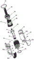
Fig. 2 is an exploded view of an intermediate housing of the pruning shears of fig. 1, in which the motor-reducer assembly is housed.
Detailed Description
Fig. 1 shows a pruning shears 10 having a main housing 12, the main housing 12 forming a handle 14. The main housing 12 is preferably constructed of a plastic or composite material and includes an upper shell 12a and a lower shell 12b, which are assembled by screwing the lower shell 12b to the upper shell 12 a. In addition to the handle, the main housing is used for attaching a cutting element. For example, an attachment bracket for the stationary blade 20 is screwed to the upper case. The housing also serves to accommodate and fix the elements of the pruning shears. In this way, it absorbs the load of the cutting member and the load generated by the internal element.
The main housing 12 accommodates a motor 30, a planetary reducer 32, and a ball screw nut mechanism 34. The ball screw nut mechanism 34 converts the rotational motion of the motor into a translational motion. It is connected to the cam 22 of the movable blade 24 by a link 36. The cam is moved by the link and causes the movable blade 24 to pivot about a pivot 26, which pivot 26 connects the movable blade 24 to the stationary blade 20. The movable blade 24 can in particular pivot from an open rest position to a closed position on the stationary blade and vice versa. The movement of the blade is controlled by a trigger 16 disposed at the front of the handle 14.
The trigger 16 is associated with a position sensor and a printed circuit board configured to generate control of the motor.
In fig. 1, the motor and reducer are mounted in an intermediate housing 40. The intermediate housing comprises a first portion 42, the first portion 42 being designed to accommodate and be in thermal contact with the electric machine. The first portion 42 may be formed, for example, as a sleeve in which the motor is received by an interference fit. The second portion 44 of the intermediate housing serves as an attachment flange for the speed reducer 32 to the motor. The second portion 44 of the intermediate housing may also be formed as a sleeve for accommodating the retarder.
In a simpler version, the retarder may not be accommodated in the intermediate housing. However, it is advantageous to mount the assembly consisting of the motor and the reducer in the intermediate housing. This thus serves not only as a heat sink but also as an attachment point for holding the reducer on the motor. The motor 30 may have a housing integral therewith that is inserted into the first portion 42 of the intermediate housing. The intermediate housing can also be used as a housing or support for the elements constituting the motor and/or the reducer. This other possibility is described with reference to fig. 2.
As mentioned above, by means of the intermediate housing, the motor-reducer unit can be tested before assembly with the other elements of the pruning shears and before mounting it in the main housing
Returning to fig. 1, it is seen that the intermediate housing 40 is provided with a heat sink 50. The heat sink 50 includes two heat radiating fins 52a, 52b, the fins 52a, 52b protruding out of the main housing 12 through suitable openings. The heat sink fins are arranged at one end of the main housing or tool body opposite the end holding the blades 20, 24 of the cutter. The heat sink mainly provides a cooling function. The heat sink facilitates dissipation of thermal energy generated by the motor and/or the speed reducer and transfer to the intermediate housing. Dissipation of thermal energy in the heat sinks 52a, 52b reduces the temperature inside the main housing 12 and limits heat build-up in the handle 14.
The fins 52a, 52b at the rear of the handle are curved in the direction of the handle, with a radius of curvature that can be adapted to the hand of the user. Thus, the heat sink 50 also serves as a first protective shield for the handle (more specifically, the hand of the user grasping the handle). The second shroud 54 extends the first shroud formed by the heat sink 50 to the front of the pruning shears, which houses the cutting member. The second shield 54 may be metal or plastic. It extends alongside the handle 14 and forms a shield 56 for the trigger 16.
A second shroud 54 is attached to the main housing 12 in front of the trigger 16. It is also attached to the heat sink 50 by pins 58. The use of a heat sink as an attachment to the shroud provides a strong anchor for the shroud and contributes to the overall robustness of the pruning shears.
The connector 60 is positioned at the rear of the pruning shears near the motor 30. Which is used to connect the pruning shears 10 to a remote power source via a power cord. Like the power cord, fig. 1 does not show a power source such as a battery.
Fig. 2 shows a specific embodiment of the intermediate housing and the motor-reducer assembly accommodated in the intermediate housing 40.
The housing 40 of fig. 2 is represented in the form of two half- shells 40a, 40b, which half- shells 40a, 40b directly serve as housings for the elements of the motor 30 and the reducer 32. In particular, the first portion 42 of the intermediate housing is designed to house the stator 64 of the electric machine. A pin 62 is visible at the rear of the stator 64, which pin 62 is the pin of the connector 60 mentioned with reference to fig. 1.
The rotor 66 of the motor, which is concentric with respect to the stator 64, is mounted on bearings 70, 72, the bearings 70, 72 being accommodated in corresponding housings 71, 73, respectively, of the intermediate housing 40.
Similarly, the second portion 44 of the intermediate housing 40 no longer serves simply as an attachment flange for the retarder as shown in FIG. 1, but rather serves as a housing for the retarder elements. In particular, the ring gear 80 of the reducer is directly housed and fixed in the second portion 44 of the intermediate casing. In other words, the reducer has no housing of its own, but its elements are directly accommodated in the intermediate housing.
In the example shown in fig. 2, the reducer comprises three satellites 82 rotating in a ring gear 80. The satellite 82 is housed on a satellite carrier 84, rotationally driven by a pinion 68 integral with the motor shaft 66. The satellite carrier 84 is mounted on a screw 86 coaxial with the motor shaft, the screw 86 being part of the ball screw nut mechanism mentioned above with reference to fig. 1.
The two half- shells 40a, 40b of the intermediate housing are fitted by means of a first elastic ring 90 housed on a shoulder 91 of the half-shell and by means of a second elastic ring 92 housed in a recess 93 of the half-shell. The second ring is of the "snap ring/circlip" type.
It can also be observed that each half- shell 40a, 40b forms a single piece with one of the fins 52a, 52b of the heat sink.
Citations of documents
D1:FR 2614568
D2:G8614677
D3:EP 2156732
Claims (16)
1. A portable power tool comprising a motor (30), a cutting member (20, 24) and a transmission (32, 34, 36) connecting the motor to the cutting member, the motor and transmission being housed in a main housing (12),
it is characterized by comprising:
an intermediate housing (40, 42, 44) made of a heat-conducting material accommodated in the main housing (12), the intermediate housing being in thermal contact with the electric machine (30), and
-at least one heat sink (50) connected to the intermediate housing and protruding outside the main housing (12).
2. The portable power tool according to claim 1, wherein the intermediate housing (40, 42, 44) comprises two adjacent and detachable portions (40a, 40 b).
3. The portable power tool according to claim 1, wherein the intermediate housing (40, 42, 44) is made in one piece.
4. The portable power tool according to any one of the preceding claims, wherein the intermediate housing (40) is further in thermal contact with at least one transmission element.
5. The portable power tool according to any one of claims 1 to 3, wherein the transmission includes a speed reducer (32), and the intermediate housing (40) is in thermal contact with the speed reducer (32).
6. The portable power tool according to claim 5, wherein the speed reducer (32) includes a ring gear (80) that is directly attached to the intermediate housing (40).
7. The portable power tool of claim 5, wherein the intermediate housing (40) includes a flange (44) for mounting the speed reducer to the motor.
8. The portable power tool according to any one of claims 1-3, wherein the motor comprises a stator (64) and roller bearings (70, 72) directly fixed to the intermediate housing (40).
9. The portable power tool according to any one of claims 1 to 3, wherein the motor has a case inserted into the intermediate housing.
10. The portable power tool according to any one of claims 1-3, wherein the heat sink (50) is made in one piece with the intermediate housing (40).
11. The portable power tool according to any one of claims 1-3, wherein the cutting member (20, 24) is integral with a first end of the main housing (12), and wherein the heat sink (50) protrudes outside the main housing at a second end of the main housing substantially opposite the first end.
12. The portable power tool according to any one of claims 1 to 3, wherein the heat sink (50) has two heat radiating fins (52a, 52 b).
13. The portable power tool according to any one of claims 1-3, wherein the main housing forms a handle (14), and wherein the intermediate housing (40) extends inside the handle (14).
14. The portable power tool according to claim 13, wherein the handle (14) is provided with a shield (54) connected to the heat sink (50).
15. The portable power tool according to claim 10, wherein the portable power tool is a pruning shears and the heat sink (50) is arranged near a handle (14) of the pruning shears to form a protective shield for the handle.
16. The portable power tool of claim 1, wherein the portable power tool is a pruning shears.
Applications Claiming Priority (3)
| Application Number | Priority Date | Filing Date | Title |
|---|---|---|---|
| FR1461405A FR3028716B1 (en) | 2014-11-25 | 2014-11-25 | ELECTROPORTATIVE TOOL, ESPECIALLY AN ELECTRICAL SECTOR WITH THERMAL DISSIPATOR. |
| FR14/61405 | 2014-11-25 | ||
| PCT/FR2015/052964 WO2016083695A1 (en) | 2014-11-25 | 2015-11-03 | Hand-held power tool, and in particular electric pruning shears with heat sink |
Publications (2)
| Publication Number | Publication Date |
|---|---|
| CN106998656A CN106998656A (en) | 2017-08-01 |
| CN106998656B true CN106998656B (en) | 2020-05-29 |
Family
ID=52392090
Family Applications (1)
| Application Number | Title | Priority Date | Filing Date |
|---|---|---|---|
| CN201580063718.8A Active CN106998656B (en) | 2014-11-25 | 2015-11-03 | Portable electric tool, in particular electric pruning shears with a heat sink |
Country Status (9)
| Country | Link |
|---|---|
| US (1) | US10091947B2 (en) |
| EP (1) | EP3223597B2 (en) |
| JP (1) | JP6557350B2 (en) |
| KR (1) | KR102516682B1 (en) |
| CN (1) | CN106998656B (en) |
| BR (1) | BR112017007573B1 (en) |
| ES (1) | ES2718942T5 (en) |
| FR (1) | FR3028716B1 (en) |
| WO (1) | WO2016083695A1 (en) |
Families Citing this family (9)
| Publication number | Priority date | Publication date | Assignee | Title |
|---|---|---|---|---|
| JP2020069259A (en) * | 2018-11-01 | 2020-05-07 | 株式会社マキタ | Charging type shear |
| FR3106953B1 (en) | 2020-02-12 | 2022-04-01 | Innovation Fabrication Commercialisation Infaco | Forced ventilation pruner |
| JP6830558B1 (en) * | 2020-04-21 | 2021-02-17 | アルスコーポレーション株式会社 | Electric pruning shears |
| US11708751B2 (en) * | 2020-08-13 | 2023-07-25 | Saudi Arabian Oil Company | Method of deploying carbon dioxide foam flooding in an oil reservoir |
| AU2021104983A4 (en) | 2020-09-10 | 2021-09-30 | Techtronic Cordless Gp | Blade replacement mechanism of electric instrument |
| KR102524087B1 (en) * | 2020-12-11 | 2023-04-19 | 심상용 | Automatic cutting device for trim sprouts |
| CN112514673A (en) * | 2020-12-24 | 2021-03-19 | 东莞市嘉航实业有限公司 | Electric scissors blade bidirectional driving mechanism and electric scissors |
| USD1000243S1 (en) * | 2021-07-09 | 2023-10-03 | Suzhou Ailixi Brushless Motor Co., Ltd. | Electric scissors |
| USD1003137S1 (en) * | 2022-03-25 | 2023-10-31 | Innovation Fabrication Commercialisation Infaco | Hedge trimmer |
Citations (5)
| Publication number | Priority date | Publication date | Assignee | Title |
|---|---|---|---|---|
| CN1440075A (en) * | 2002-02-20 | 2003-09-03 | 惠普公司 | Radiator by utilizing its shield |
| EP1688032A1 (en) * | 2005-02-03 | 2006-08-09 | KMK Kunststoff- und Montagetechnik GmbH | Gardening implement with an electromotive drive system with multiphase motor |
| CN102132133A (en) * | 2008-08-22 | 2011-07-20 | 佩朗股份有限公司 | Portable electric tool equipped with a device enabling the relative position of two members of said tool at least one of which can move to be determined |
| CN203537937U (en) * | 2013-09-26 | 2014-04-16 | 宁波市镇海长城汽车摩托车部件厂 | Novel electrical fruit tree pruning shears |
| CN104094782A (en) * | 2014-06-20 | 2014-10-15 | 宁波大叶园林设备有限公司 | Lithium electric chain saw provided with cooling jacket for protecting batteries |
Family Cites Families (33)
| Publication number | Priority date | Publication date | Assignee | Title |
|---|---|---|---|---|
| US1755511A (en) * | 1928-05-28 | 1930-04-22 | Frank A Miller | Power shears |
| US1758485A (en) * | 1929-02-28 | 1930-05-13 | Frank D Vartanian | Power shears |
| US2020567A (en) * | 1934-08-10 | 1935-11-12 | Noske Rudolf | Mechanical movement shears |
| US2287347A (en) * | 1941-05-06 | 1942-06-23 | Daniel F Young | Electric scissors |
| US2621404A (en) * | 1952-02-21 | 1952-12-16 | Carl M Koons | Motor-driven shear means |
| US3971132A (en) * | 1971-09-17 | 1976-07-27 | Rockwell International Corporation | Saber saw |
| US3945120A (en) * | 1974-04-25 | 1976-03-23 | Milwaukee Electric Tool Corporation | Vibration dampening and heat sink mechanism for a reciprocating power saw |
| DE8614677U1 (en) | 1986-05-30 | 1986-07-17 | NIKO Nippert Maschinenbau, 77815 Bühl | Mechanical hand shears, especially for agriculture |
| FR2614568B1 (en) | 1987-04-28 | 1989-07-28 | Pellenc & Motte | PORTABLE POWER TOOL WITH POSITION CONTROL |
| US6634107B2 (en) * | 1999-03-12 | 2003-10-21 | Hitachi Koki Co., Ltd. | Cutting mechanism for a saber saw |
| DE60106085T2 (en) * | 2000-12-05 | 2005-10-06 | Hispaes, S.A. | PORTABLE SCISSORS WITH MOTOR DRIVE |
| JP5034348B2 (en) | 2006-07-20 | 2012-09-26 | マックス株式会社 | Electric scissors |
| US20080173138A1 (en) * | 2006-08-15 | 2008-07-24 | Dayton Douglas C | Systems and methods of a vacuum cup bulb changer power tool system with interchangeable functional attachments |
| AT504324B8 (en) * | 2007-04-20 | 2008-09-15 | Strube Karl | ELECTRIC SCISSORS |
| US20090014251A1 (en) * | 2007-07-11 | 2009-01-15 | Mccracken Oliver Wendell | Positioning system |
| US20090049694A1 (en) * | 2007-08-21 | 2009-02-26 | Gary Jay Morris | Electric shaver apparatus with actively cooled surface |
| EP2036681A1 (en) † | 2007-09-14 | 2009-03-18 | Alexander Kipfelsberger | Power screwdriver, in particular shut-off screwdriver |
| FR2935106B1 (en) * | 2008-08-22 | 2010-09-17 | Pellenc Sa | PORTABLE ELECTROPORTATIVE TOOL |
| FR2935284B1 (en) * | 2008-08-26 | 2010-09-17 | Pellenc Sa | ELECTROPORTATIVE TOOL MECHANIZED WITH TWO SLEEVES |
| KR101132328B1 (en) | 2009-03-23 | 2012-04-05 | 로아텍 주식회사 | electric-pruning shears with trigger. |
| CN101941200B (en) † | 2009-07-03 | 2015-03-25 | 德昌电机(深圳)有限公司 | Electric tool and motor assembly thereof |
| CN201455943U (en) † | 2009-07-08 | 2010-05-12 | 德昌电机(深圳)有限公司 | Electric tool |
| CN201493868U (en) * | 2009-09-08 | 2010-06-02 | 南京德朔实业有限公司 | Electric shears |
| US20110214292A1 (en) * | 2010-03-02 | 2011-09-08 | Moon Heh | Electric scissors having a replaceable blade |
| FR2957834B1 (en) | 2010-03-24 | 2012-03-09 | Infaco | DEVICE FOR POSITIONALLY CONTROLLING TWO ELEMENTS RELATIVE TO EACH OTHER, SUCH AS BLADES OF CUTTER GENERATOR TOOLS AND CUTTING TOOL COMPRISING SAME |
| WO2012079519A1 (en) * | 2010-12-15 | 2012-06-21 | 苏州宝时得电动工具有限公司 | Cutting accessory and oscillating power tool using same |
| US20120174416A1 (en) * | 2011-01-07 | 2012-07-12 | Ci, Llc | Electric pruning device |
| WO2013093619A2 (en) † | 2011-12-19 | 2013-06-27 | Carine Elen | Motorized scrubbing, buffing, and polishing tool |
| EP2659764B1 (en) † | 2012-05-04 | 2020-08-12 | Felco SA | Portable electric tool and method for assembling such a portable electric tool |
| JP5632884B2 (en) * | 2012-08-15 | 2014-11-26 | 株式会社マキタ | Power tools |
| JP2013166244A (en) | 2013-04-01 | 2013-08-29 | Max Co Ltd | Power tool |
| US9796099B2 (en) * | 2014-04-08 | 2017-10-24 | Terry Sandefur | Cutting apparatus |
| US20150313089A1 (en) * | 2014-04-30 | 2015-11-05 | Remo Francesco CECCHI | Cutting system |
-
2014
- 2014-11-25 FR FR1461405A patent/FR3028716B1/en active Active
-
2015
- 2015-11-03 ES ES15804167T patent/ES2718942T5/en active Active
- 2015-11-03 JP JP2017546047A patent/JP6557350B2/en active Active
- 2015-11-03 CN CN201580063718.8A patent/CN106998656B/en active Active
- 2015-11-03 EP EP15804167.3A patent/EP3223597B2/en active Active
- 2015-11-03 WO PCT/FR2015/052964 patent/WO2016083695A1/en active Application Filing
- 2015-11-03 BR BR112017007573-3A patent/BR112017007573B1/en active IP Right Grant
- 2015-11-03 KR KR1020177017620A patent/KR102516682B1/en active IP Right Grant
- 2015-11-03 US US15/513,292 patent/US10091947B2/en active Active
Patent Citations (5)
| Publication number | Priority date | Publication date | Assignee | Title |
|---|---|---|---|---|
| CN1440075A (en) * | 2002-02-20 | 2003-09-03 | 惠普公司 | Radiator by utilizing its shield |
| EP1688032A1 (en) * | 2005-02-03 | 2006-08-09 | KMK Kunststoff- und Montagetechnik GmbH | Gardening implement with an electromotive drive system with multiphase motor |
| CN102132133A (en) * | 2008-08-22 | 2011-07-20 | 佩朗股份有限公司 | Portable electric tool equipped with a device enabling the relative position of two members of said tool at least one of which can move to be determined |
| CN203537937U (en) * | 2013-09-26 | 2014-04-16 | 宁波市镇海长城汽车摩托车部件厂 | Novel electrical fruit tree pruning shears |
| CN104094782A (en) * | 2014-06-20 | 2014-10-15 | 宁波大叶园林设备有限公司 | Lithium electric chain saw provided with cooling jacket for protecting batteries |
Also Published As
| Publication number | Publication date |
|---|---|
| FR3028716B1 (en) | 2016-11-25 |
| BR112017007573B1 (en) | 2021-02-09 |
| FR3028716A1 (en) | 2016-05-27 |
| US20170251607A1 (en) | 2017-09-07 |
| ES2718942T3 (en) | 2019-07-05 |
| US10091947B2 (en) | 2018-10-09 |
| JP2017536136A (en) | 2017-12-07 |
| EP3223597B2 (en) | 2022-10-26 |
| CN106998656A (en) | 2017-08-01 |
| EP3223597A1 (en) | 2017-10-04 |
| WO2016083695A1 (en) | 2016-06-02 |
| JP6557350B2 (en) | 2019-08-07 |
| ES2718942T5 (en) | 2023-03-10 |
| EP3223597B1 (en) | 2019-01-09 |
| KR102516682B1 (en) | 2023-03-31 |
| KR20170088423A (en) | 2017-08-01 |
| BR112017007573A2 (en) | 2018-01-30 |
Similar Documents
| Publication | Publication Date | Title |
|---|---|---|
| CN106998656B (en) | Portable electric tool, in particular electric pruning shears with a heat sink | |
| US20110258859A1 (en) | Cutting device and method | |
| JP2002154630A (en) | Roller with built-in motor | |
| US11219159B2 (en) | Grass trimmer | |
| US10843324B2 (en) | Visible motor saw head layout | |
| CN212653398U (en) | Long rod type electric tool | |
| US20130087352A1 (en) | Portable ice breaking tool with two reciprocating blades | |
| KR20100058206A (en) | Handpiece including cooling means | |
| US20200061796A1 (en) | Ergonomic apparatus for handheld tools and powered tools | |
| CN208572785U (en) | Handheld garden tool | |
| JP6223848B2 (en) | Impact tool | |
| CN212794851U (en) | Long rod type electric tool | |
| EP2875909A1 (en) | Supporting device for at least one electrical unit of electrically driveable tools | |
| CN113305789B (en) | Long rod type electric tool | |
| CN113305788B (en) | Long rod type electric tool | |
| JP4606244B2 (en) | Brush cutter | |
| ES2312076T3 (en) | MOTOR DRIVE UNIT FOR FOOD PROCESSING TOOLS. | |
| CN212794852U (en) | Long rod type electric tool | |
| CN210840785U (en) | Charging type mini electric chain saw | |
| AU2006328015B2 (en) | Improvements in shearing equipment | |
| CN219588743U (en) | Multidirectional heat dissipation type LED fluorescent tube | |
| JPS63216622A (en) | Electric saw | |
| CN208972064U (en) | A kind of plant heading machine | |
| JP2006311827A (en) | Bush cutter | |
| EP1508267A1 (en) | Device for cutting vegetation or for other applications, with electric motor and reducing gear |
Legal Events
| Date | Code | Title | Description |
|---|---|---|---|
| PB01 | Publication | ||
| PB01 | Publication | ||
| SE01 | Entry into force of request for substantive examination | ||
| SE01 | Entry into force of request for substantive examination | ||
| GR01 | Patent grant | ||
| GR01 | Patent grant |