Welding device for side reinforcing ribs of energy-saving inner wall
Technical Field
The invention relates to the field of heat-insulating walls, in particular to a welding device for a side reinforcing rib of an energy-saving inner wall.
Background
The application of the phenolic aldehyde wall body in the field of wall body heat preservation is very extensive, and after the phenolic aldehyde wall body was in the same place by the crisscross stack of cystosepiment and W steel wire, still need weld the structural strength of upside strengthening rib in the both sides of cystosepiment and guarantee the phenolic aldehyde wall body, in the actual operation process because the quantity of welding point is many, work load is big, and the welding is difficult to the location, influences the welding effect, is restricting the rapid development of heat preservation wall body material.
The welding device for the side reinforcing ribs of the energy-saving inner wall is high in automation level, meanwhile, the welding device comprises a straightening mechanism, a steel wire blanking mechanism, an upper shearing mechanism, an upper clamping mechanism, a welding mechanism, a steel wire guiding mechanism, a lower clamping mechanism, a tail cutting mechanism and a lower guiding mechanism, the straightening mechanism, the steel wire blanking mechanism, the upper shearing mechanism, the upper clamping mechanism, the welding mechanism, the steel wire guiding mechanism, the lower clamping mechanism, the tail cutting mechanism and the lower guiding mechanism are cooperatively operated by the mechanisms, so that the operations of blanking, guiding, upper and lower clamping, upper shearing, lower straightening, welding, tail cutting and the like of the side reinforcing ribs are completed, manual welding is replaced by mechanical automatic production, and the working efficiency is improved exponentially.
Disclosure of Invention
Aiming at the defects existing in the problems, the invention provides a welding device for a side reinforcing rib of an energy-saving inner wall.
In order to achieve the above object, the present invention provides a welding device for a side reinforcing rib of an energy-saving interior wall, comprising:
the device comprises a top frame, an underframe and side frames, wherein two side frames are fixedly connected with the top frame and the underframe to form a frame structure, and two middle frames are symmetrically arranged between the top frame and the underframe;
the steel wire blanking mechanism is fixedly arranged above the middle part of the top frame and comprises a driving wheel and a driven wheel, and steel wire grooves are machined on the circumferences of the driving wheel and the driven wheel and used for lateral reinforcing ribs to pass through;
the straightening mechanism is positioned above the steel wire blanking mechanism;
the lifting mechanisms are symmetrically arranged between the top frame and the bottom frame, each lifting mechanism comprises a negative plate, the upper end of each negative plate extends into the corresponding guide seat, a negative electrode is fixedly arranged on each negative plate, and the lower end of each negative plate is connected with a lifting cylinder through a flange;
the welding mechanisms are vertically and symmetrically arranged on the side frames and comprise welding cylinders, the shaft ends of the welding cylinders are provided with anodes, and the anodes correspond to the cathodes;
the upper clamping mechanism is symmetrically fixed above the welding mechanism and comprises an upper clamping head and an upper clamping cylinder, the upper clamping head is controlled by the upper clamping cylinder to be loosened and clamped, and the upper clamping mechanism is positioned above the upper guide plate and connected with the upper propelling cylinder;
the lower clamping mechanisms are symmetrically fixed below the welding mechanism and comprise lower clamping heads and lower clamping cylinders, the lower clamping heads are controlled by the lower clamping cylinders to be loosened and clamped, the lower clamping mechanisms are located above the lower guide plate and connected with the lower pushing cylinders, and the bottoms of the lower guide plate are fixedly connected with the stretching cylinders;
the upper shearing mechanism is symmetrically arranged above the upper clamping mechanism and comprises a cutter shaft and a fan-shaped cutter below the cutter shaft, the cutter shaft penetrates through a fixed block, a steel wire hole is processed in the fixed block, and the steel wire hole falls in a fan-shaped area of the fan-shaped cutter;
the steel wire guide mechanism comprises a guide movable part and a guide fixing part, the guide fixing part is fixed between the upper clamping mechanism and the lower clamping mechanism, the guide movable part is matched with the guide fixing part, a processing channel between the guide movable part and the guide fixing part is used for the lateral reinforcing ribs to pass through, the upper end and the lower end of the guide movable part are respectively and fixedly connected with a U-shaped connecting rod, and the upper end and the lower end of the guide fixing part are correspondingly connected with the U-shaped connecting rod through a hinge mechanism II;
and the tail cutting mechanism is positioned below the welding mechanism and comprises a tail cutting knife which is movably connected to the bottom frame.
The lower guide mechanism is fixed above the middle part of the underframe and comprises a shaft, and a rolling body is sleeved on the shaft.
As a further improvement of the invention, the driving wheel is fixedly connected with the power gear, the driven wheel is fixedly connected with the driven gear, the driven wheel is arranged in the driven wheel sleeve, and the driven wheel sleeve is hinged with the pressing cylinder and is hinged with the top frame.
As a further improvement of the invention, the straightening mechanism consists of regularly arranged straightening rollers, and the horizontal center distance of two adjacent straightening rollers is smaller than the diameter of the straightening rollers.
As a further improvement of the invention, the guide seats are symmetrically fixed below the top frame, and the lifting cylinders are symmetrically fixed above the bottom frame.
As a further improvement of the invention, the welding cylinder is guided by a guide sleeve, and the guide sleeve is fixed on the middle frame.
As a further improvement of the invention, the position of the fixed block is fixed, and the cutter shaft is connected with the upper shearing cylinder through a hinge mechanism III.
As a further improvement of the invention, the U-shaped connecting rod is also connected with a hinge cylinder through a hinge mechanism I, and the hinge cylinder is movably connected on the side frame.
As a further improvement of the invention, the tail cutting knife is connected with the tail cutting cylinder through a hinge mechanism, and the tail cutting cylinder is connected on the bottom frame through a hinge.
As a further improvement of the invention, the shaft is arranged on a shaft bracket, and the shaft bracket is fixed at the middle position of the underframe by a bolt.
As a further improvement of the invention, when the welding mechanism works, the welding cylinder is divided into a single part and a double part to be operated intermittently in sequence, so that the instantaneous working current is reduced.
The invention has the beneficial effects that:
welding set right-hand member is connected with feed arrangement, realizes the butt joint of feeding and welded, and automatic level is high, and simultaneously, the device includes aligning mechanism, steel wire unloading mechanism, goes up the mechanism of cutting off, goes up fixture, welding mechanism, steel wire guiding mechanism, lower fixture, cuts out tail mechanism, guiding mechanism down, by a plurality of mechanisms work in coordination, accomplish the unloading of side strengthening rib, the direction, centre gripping from top to bottom, cut off on, stretch straight, welding, cut out a plurality of operations such as tail, replace manual welding by mechanical automation production, work efficiency improves at double.
Drawings
FIG. 1 is a left side view of a welding apparatus for a side reinforcing bar of an energy saving inner wall according to the present invention;
FIG. 2 is a front view of a welding apparatus for side reinforcing bars of an energy-saving interior wall according to the present invention;
FIG. 3 is a front view of a steel wire blanking mechanism;
FIG. 4 is a top view of the wire blanking mechanism;
FIG. 5 is a top view of the upper clamping mechanism;
FIG. 6 is a top view of the lower clamping mechanism;
FIG. 7 is a left side view of FIG. 6;
FIG. 8 is a front view of the upper cutting mechanism;
FIG. 9 is a top view of the upper shear mechanism;
FIG. 10 is a view taken along line A of FIG. 8;
FIG. 11 is a front view of the welding mechanism and the lifting mechanism;
FIG. 12 is a partial view of the welding mechanism and the lifting mechanism;
FIG. 13 is a view taken along line B of FIG. 12;
FIG. 14 is a front view of the wire guide mechanism;
FIG. 15 is a top view of the wire guide mechanism;
FIG. 16 is a top view of the tail trimmer mechanism;
FIG. 17 is a front view of the lower guide mechanism;
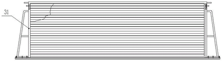
FIG. 18 is a front view of the load carrier (before welding);
FIG. 19 is an enlarged view of a portion of FIG. 18;
FIG. 20 is a top view of FIG. 19;
FIG. 21 is an enlarged view of a portion of FIG. 20;
FIG. 22 is a front view of the cargo holder (after welding);
FIG. 23 is an enlarged view of a portion of FIG. 22;
FIG. 24 is a top view of FIG. 23;
fig. 25 is a partially enlarged view of fig. 24.
In the figure: 1. a chassis; 2. a lifting mechanism; 21. a guide seat; 22. a negative plate; 23. a negative electrode; 231. a welding point; 24. a flange; 25. a lifting cylinder; 3. a side frame; 4. a middle frame; 5. a lower guide mechanism; 51. a pedestal; 52. a shaft; 53. a rolling body; 6. a tail cutting mechanism; 61. a tail cutting cylinder; 62. a hinge mechanism; 63. cutting a tail cutter; 7. a lower clamping mechanism; 71. a lower clamp head; 72. a lower clamping cylinder; 8. a steel wire guide mechanism; 81. a hinge cylinder; 82. a hinge mechanism I; 83. a hinge mechanism II; 84. a U-shaped connecting rod; 85. a guide movable part; 86. a guide fixing part; 9. a welding mechanism; 91. welding the cylinder; 92. a guide sleeve; 93. a positive electrode; 10. an upper clamping mechanism; 101. an upper clamping head; 102. an upper clamping cylinder; 11. a shearing mechanism is arranged; 111. an upper shearing cylinder; 112. a hinge mechanism III; 113. a cutter shaft; 114. a fixed block; 1141. steel wire holes; 115. a fan-shaped knife; 12. a top frame; 13. a steel wire blanking mechanism; 131. a driving wheel; 132. a power gear; 133. a driven wheel; 134. a driven gear; 135. a driven wheel sleeve; 136. a pressing cylinder; 14. a straightening mechanism; 141. straightening rollers; 15. side reinforcing ribs; 16. an upper guide plate; 17. an air cylinder is pushed upwards; 18. a lower guide plate; 19. stretching a straight cylinder; 20. pushing down the air cylinder; 31. a load carrier; 32. a foam board; 33. w steel wires;
Detailed Description
As shown in the drawings, the welding device for the side reinforcing ribs of the energy-saving inner wall according to the embodiment of the invention comprises: as shown in fig. 1, two side frames 3 are fixedly connected with a top frame 12 and a bottom frame 1 to form a frame structure, and two middle frames 4 are symmetrically arranged between the top frame 12 and the bottom frame 1; the steel wire blanking mechanism 13 is fixedly installed above the middle part of the top frame 12, as shown in fig. 3 and 4, the steel wire blanking mechanism 13 includes a driving wheel 131 and a driven wheel 133, and steel wire grooves are processed on the circumferences of the driving wheel 131 and the driven wheel 133 for the side reinforcing ribs 15 to pass through; the driving wheel 131 is fixedly connected with the power gear 132, the driven wheel 133 is fixedly connected with the driven gear 134, the driven wheel 133 is arranged in a driven wheel sleeve 135, and the driven wheel sleeve 135 is hinged with the pressing cylinder 136 and is hinged with the top frame 12; as shown in fig. 1, the straightening mechanism 14 is located above the wire blanking mechanism 13; the straightening mechanism 14 is composed of regularly arranged straightening rollers 141, and the horizontal center distance between two adjacent straightening rollers 141 is smaller than the diameter of the straightening rollers 141; as shown in fig. 11 and 12, two sets of lifting mechanisms 2 are symmetrically installed between the top frame 12 and the bottom frame 1, each lifting mechanism 2 comprises a negative plate 22, the upper end of each negative plate 22 extends into the guide seat 21, a negative electrode 23 is fixedly installed on each negative plate 22, and the lower end of each negative plate 22 is connected with a lifting cylinder 25 through a flange 24; the guide seats 21 are symmetrically fixed below the top frame 12, and the lifting cylinders 25 are symmetrically fixed above the bottom frame 1; as shown in fig. 11 and 12, the welding mechanisms 9 are vertically and symmetrically arranged on the side frame 3, the welding mechanisms 9 include welding cylinders 91, the shaft ends of the welding cylinders 91 are provided with positive electrodes 93, and the positive electrodes 93 correspond to the negative electrodes 23; the welding cylinder 91 is guided by the guide sleeve 92, the guide sleeve 92 is fixed on the middle frame 4, and when the welding mechanism 9 works, the welding cylinder 91 performs single-double sequential intermittent actions; as shown in fig. 1, the upper clamping mechanism 10 is symmetrically fixed above the welding mechanism 9, as shown in fig. 5, the upper clamping mechanism 10 comprises an upper clamping head 101 and an upper clamping cylinder 102, the upper clamping head 101 is controlled by the upper clamping cylinder 102 to be loosened and clamped, and the upper clamping mechanism 10 is located above the upper guide plate 16 and connected with the upper propulsion cylinder 17; as shown in fig. 1, the lower clamping mechanisms 7 are symmetrically fixed below the welding mechanism 9, as shown in fig. 6 and 7, the lower clamping mechanism 7 comprises a lower clamping head 71 and a lower clamping cylinder 72, the lower clamping head 71 is controlled by the lower clamping cylinder 72 to be loosened and clamped, the lower clamping mechanism 7 is positioned above the lower guide plate 18 and connected with the lower pushing cylinder 20, and the bottom of the lower guide plate 18 is fixedly connected with the straightening cylinder 19; as shown in fig. 1, the upper shearing mechanism 11 is symmetrically installed above the upper clamping mechanism 10, as shown in fig. 8, 9 and 10, the upper shearing mechanism 11 includes a knife shaft 113 and a fan-shaped knife 115 below the knife shaft 113, the knife shaft 113 passes through a fixing block 114, the fixing block 114 is fixed in position, a steel wire hole 1141 is processed on the fixing block 114, the steel wire hole 1141 falls into a fan-shaped area of the fan-shaped knife 115, and the knife shaft 113 is connected with an upper shearing cylinder 111 through a hinge mechanism III 112; as shown in fig. 14 and 15, the wire guide mechanism 8 includes a guide movable portion 85 and a guide fixed portion 86, the guide fixed portion 86 is fixed between the upper clamping mechanism 10 and the lower clamping mechanism 7, the guide movable portion 85 is matched with the guide fixed portion 86, a processing channel between the guide movable portion 85 and the guide fixed portion 86 is used for the side reinforcing rib 15 to pass through, the upper end and the lower end of the guide movable portion 85 are respectively and fixedly connected with the U-shaped connecting rod 84, the upper end and the lower end of the guide fixed portion 86 are respectively connected with the U-shaped connecting rod 84 through a hinge mechanism II83, the U-shaped connecting rod 84 is further connected with a hinge cylinder 81 through a hinge mechanism I82, and the hinge cylinder 81 is movably connected with the side frame 3; as shown in fig. 1, the tail cutting mechanism 6 is located below the welding mechanism 9, as shown in fig. 16, the tail cutting mechanism 6 comprises a tail cutting knife 63, the tail cutting knife 63 is movably connected to the underframe 1, the tail cutting knife 63 is connected with a tail cutting cylinder 61 through a hinge mechanism 62, and the tail cutting cylinder 61 is hinged to the underframe 1; as shown in fig. 1, the lower guide mechanism 5 is fixed above the middle part of the underframe 1, as shown in fig. 17, the lower guide mechanism 5 comprises a shaft 52, a rolling body 53 is sleeved on the shaft 52, the shaft 52 is installed on a shaft bracket 51, and the shaft bracket 51 is fixed at the middle part of the underframe 1 by bolts;
welding set right-hand member is connected with feed arrangement, realize feeding and welded butt joint, automatic level is high, and simultaneously, the device is including aligning mechanism, steel wire unloading mechanism, go up the shearing mechanism, go up fixture, welding mechanism, steel wire guiding mechanism, lower fixture, cut out tail mechanism, lower guiding mechanism, by a plurality of mechanisms in coordination function, accomplish the unloading of side strengthening rib, the direction, centre gripping from top to bottom, cut off on, stretch straight down, welding, cut out a plurality of operations such as tail, replace manual welding by mechanical automation production, work efficiency improves at double.
In particular, in order to facilitate understanding of the present invention, the operation of the apparatus is described in the following steps;
feeding: the right end of the welding device is connected with the feeding device, the W steel wires and the foam plates are arranged on the goods carrying rack in a staggered mode (as shown in figures 18-21), and the goods carrying rack is intermittently conveyed to the left by the feeding device.
Blanking: as shown in fig. 3 and 4, the pressing cylinder acts, the driven wheel sleeve is hinged with the pressing cylinder and is hinged with the top frame, the driven gear arranged in the driven wheel sleeve is meshed with the driving gear and rotates along with the driving gear, correspondingly, the side reinforcing ribs are downwards fed under the action of friction force in the steel wire grooves of the driving gear and the driven wheel, and the steel wire is straightened by the straightening roller before being fed due to the straightening mechanism arranged above the steel wire feeding mechanism.
Guiding: as shown in fig. 14 and 15, when the steel wire feeding mechanism feeds materials, the steel wire guide mechanism is closed, namely, the working surfaces of the guide movable part and the guide fixing part are attached, the side reinforcing rib passes through a channel between the guide movable part and the guide fixing part, when the side reinforcing rib reaches the required length, the PLC controls the pressing cylinder to reset, the driving wheel and the driven wheel are separated, and the side reinforcing rib stops feeding.
And (3) clamping up and down: after the steel wire blanking mechanism stops blanking, the upper clamping cylinder acts, the upper clamping head portion clamps the upper portion of the side reinforcing rib, the lower clamping cylinder acts, and the lower clamping head portion clamps the lower portion of the side reinforcing rib.
And (3) upper shearing: after the side reinforcing ribs finish up-down clamping, the upper shearing mechanism acts, as shown in fig. 8-11, the upper shearing cylinder drives the cutter shaft to rotate through the hinge mechanism III, and the fan-shaped cutter below the cutter shaft shears the side reinforcing ribs penetrating through the fixing block.
Stretching the materials to be straight: as shown in FIG. 6, after the upper shearing is completed, the stretching cylinder is operated, the lower clamping mechanism is moved downward as a whole, while the upper clamping mechanism is not moved, and the side reinforcing bars which are sheared at the upper part are stretched and straightened.
And (3) pushing up and down: after the side reinforcing ribs are stretched straight, as shown in fig. 5, the upper clamping mechanism is pushed by the upper pushing cylinder, the upper clamping mechanism is pushed inwards under the guiding action of the upper guide plate, meanwhile, the lower clamping mechanism is pushed by the lower pushing cylinder, the lower clamping mechanism is synchronously pushed inwards under the guiding action of the lower guide plate until the side reinforcing ribs are in contact with the W steel wire, preparation is made for the next welding, and the contact condition of the side reinforcing ribs and the W steel wire at the moment is shown in fig. 25.
Welding: after propelling from top to bottom, the elevating system moves, as shown in fig. 11 and fig. 12, the elevating cylinder drives the negative plate to move down, the negative pole on the negative plate correspondingly moves down, the welding point on the negative pole is aligned with the positive position of the welding mechanism, the welding cylinders on two sides are controlled by the PLC to move, the welding cylinders finish welding work (can reduce instantaneous working current) in sequence according to the order of single and double numbers, welding is finished, the elevating cylinder resets, the negative pole returns to the middle position of the foam board, the negative pole does not obstruct the next feeding of the W steel wire, the goods carrier carries out the next conveying feeding by the feeding device, and preparation is made for the welding of the next side reinforcing rib.
Tail cutting: when the goods carrying rack continues to advance, the allowance part at the bottom of the welded side reinforcing rib is cut by the tail cutting mechanism, and the tail cutting mechanism specifically comprises the following parts: as shown in fig. 16, the tail cutting cylinder acts to drive the tail cutting knife movably connected to the bottom frame to rotate through the hinge mechanism, and the tail cutting knife cuts off the allowance at the bottom of the side reinforcing rib.
The above description is only a preferred embodiment of the present invention and is not intended to limit the present invention, and various modifications and changes may be made by those skilled in the art. Any modification, equivalent replacement, or improvement made within the spirit and principle of the present invention should be included in the protection scope of the present invention.