CN106964062B - Method for producing sheet - Google Patents
Method for producing sheet Download PDFInfo
- Publication number
- CN106964062B CN106964062B CN201610958649.3A CN201610958649A CN106964062B CN 106964062 B CN106964062 B CN 106964062B CN 201610958649 A CN201610958649 A CN 201610958649A CN 106964062 B CN106964062 B CN 106964062B
- Authority
- CN
- China
- Prior art keywords
- mold
- nozzle
- needle
- liquid
- filling
- Prior art date
- Legal status (The legal status is an assumption and is not a legal conclusion. Google has not performed a legal analysis and makes no representation as to the accuracy of the status listed.)
- Expired - Fee Related
Links
Images


Classifications
-
- A—HUMAN NECESSITIES
- A61—MEDICAL OR VETERINARY SCIENCE; HYGIENE
- A61M—DEVICES FOR INTRODUCING MEDIA INTO, OR ONTO, THE BODY; DEVICES FOR TRANSDUCING BODY MEDIA OR FOR TAKING MEDIA FROM THE BODY; DEVICES FOR PRODUCING OR ENDING SLEEP OR STUPOR
- A61M37/00—Other apparatus for introducing media into the body; Percutany, i.e. introducing medicines into the body by diffusion through the skin
- A61M37/0015—Other apparatus for introducing media into the body; Percutany, i.e. introducing medicines into the body by diffusion through the skin by using microneedles
-
- B—PERFORMING OPERATIONS; TRANSPORTING
- B29—WORKING OF PLASTICS; WORKING OF SUBSTANCES IN A PLASTIC STATE IN GENERAL
- B29C—SHAPING OR JOINING OF PLASTICS; SHAPING OF MATERIAL IN A PLASTIC STATE, NOT OTHERWISE PROVIDED FOR; AFTER-TREATMENT OF THE SHAPED PRODUCTS, e.g. REPAIRING
- B29C31/00—Handling, e.g. feeding of the material to be shaped, storage of plastics material before moulding; Automation, i.e. automated handling lines in plastics processing plants, e.g. using manipulators or robots
- B29C31/04—Feeding of the material to be moulded, e.g. into a mould cavity
- B29C31/041—Feeding of the material to be moulded, e.g. into a mould cavity using filling or dispensing heads placed in closed moulds or in contact with mould walls
-
- A—HUMAN NECESSITIES
- A61—MEDICAL OR VETERINARY SCIENCE; HYGIENE
- A61K—PREPARATIONS FOR MEDICAL, DENTAL OR TOILETRY PURPOSES
- A61K9/00—Medicinal preparations characterised by special physical form
- A61K9/0012—Galenical forms characterised by the site of application
- A61K9/0019—Injectable compositions; Intramuscular, intravenous, arterial, subcutaneous administration; Compositions to be administered through the skin in an invasive manner
- A61K9/0021—Intradermal administration, e.g. through microneedle arrays, needleless injectors
-
- A—HUMAN NECESSITIES
- A61—MEDICAL OR VETERINARY SCIENCE; HYGIENE
- A61K—PREPARATIONS FOR MEDICAL, DENTAL OR TOILETRY PURPOSES
- A61K9/00—Medicinal preparations characterised by special physical form
- A61K9/70—Web, sheet or filament bases ; Films; Fibres of the matrix type containing drug
- A61K9/7007—Drug-containing films, membranes or sheets
-
- A—HUMAN NECESSITIES
- A61—MEDICAL OR VETERINARY SCIENCE; HYGIENE
- A61K—PREPARATIONS FOR MEDICAL, DENTAL OR TOILETRY PURPOSES
- A61K9/00—Medicinal preparations characterised by special physical form
- A61K9/70—Web, sheet or filament bases ; Films; Fibres of the matrix type containing drug
- A61K9/7023—Transdermal patches and similar drug-containing composite devices, e.g. cataplasms
-
- B—PERFORMING OPERATIONS; TRANSPORTING
- B29—WORKING OF PLASTICS; WORKING OF SUBSTANCES IN A PLASTIC STATE IN GENERAL
- B29C—SHAPING OR JOINING OF PLASTICS; SHAPING OF MATERIAL IN A PLASTIC STATE, NOT OTHERWISE PROVIDED FOR; AFTER-TREATMENT OF THE SHAPED PRODUCTS, e.g. REPAIRING
- B29C33/00—Moulds or cores; Details thereof or accessories therefor
- B29C33/38—Moulds or cores; Details thereof or accessories therefor characterised by the material or the manufacturing process
- B29C33/3842—Manufacturing moulds, e.g. shaping the mould surface by machining
-
- B—PERFORMING OPERATIONS; TRANSPORTING
- B29—WORKING OF PLASTICS; WORKING OF SUBSTANCES IN A PLASTIC STATE IN GENERAL
- B29C—SHAPING OR JOINING OF PLASTICS; SHAPING OF MATERIAL IN A PLASTIC STATE, NOT OTHERWISE PROVIDED FOR; AFTER-TREATMENT OF THE SHAPED PRODUCTS, e.g. REPAIRING
- B29C39/00—Shaping by casting, i.e. introducing the moulding material into a mould or between confining surfaces without significant moulding pressure; Apparatus therefor
- B29C39/003—Shaping by casting, i.e. introducing the moulding material into a mould or between confining surfaces without significant moulding pressure; Apparatus therefor characterised by the choice of material
-
- B—PERFORMING OPERATIONS; TRANSPORTING
- B29—WORKING OF PLASTICS; WORKING OF SUBSTANCES IN A PLASTIC STATE IN GENERAL
- B29C—SHAPING OR JOINING OF PLASTICS; SHAPING OF MATERIAL IN A PLASTIC STATE, NOT OTHERWISE PROVIDED FOR; AFTER-TREATMENT OF THE SHAPED PRODUCTS, e.g. REPAIRING
- B29C39/00—Shaping by casting, i.e. introducing the moulding material into a mould or between confining surfaces without significant moulding pressure; Apparatus therefor
- B29C39/02—Shaping by casting, i.e. introducing the moulding material into a mould or between confining surfaces without significant moulding pressure; Apparatus therefor for making articles of definite length, i.e. discrete articles
- B29C39/026—Shaping by casting, i.e. introducing the moulding material into a mould or between confining surfaces without significant moulding pressure; Apparatus therefor for making articles of definite length, i.e. discrete articles characterised by the shape of the surface
-
- B—PERFORMING OPERATIONS; TRANSPORTING
- B29—WORKING OF PLASTICS; WORKING OF SUBSTANCES IN A PLASTIC STATE IN GENERAL
- B29C—SHAPING OR JOINING OF PLASTICS; SHAPING OF MATERIAL IN A PLASTIC STATE, NOT OTHERWISE PROVIDED FOR; AFTER-TREATMENT OF THE SHAPED PRODUCTS, e.g. REPAIRING
- B29C39/00—Shaping by casting, i.e. introducing the moulding material into a mould or between confining surfaces without significant moulding pressure; Apparatus therefor
- B29C39/22—Component parts, details or accessories; Auxiliary operations
- B29C39/24—Feeding the material into the mould
-
- A—HUMAN NECESSITIES
- A61—MEDICAL OR VETERINARY SCIENCE; HYGIENE
- A61M—DEVICES FOR INTRODUCING MEDIA INTO, OR ONTO, THE BODY; DEVICES FOR TRANSDUCING BODY MEDIA OR FOR TAKING MEDIA FROM THE BODY; DEVICES FOR PRODUCING OR ENDING SLEEP OR STUPOR
- A61M37/00—Other apparatus for introducing media into the body; Percutany, i.e. introducing medicines into the body by diffusion through the skin
- A61M37/0015—Other apparatus for introducing media into the body; Percutany, i.e. introducing medicines into the body by diffusion through the skin by using microneedles
- A61M2037/0023—Drug applicators using microneedles
-
- A—HUMAN NECESSITIES
- A61—MEDICAL OR VETERINARY SCIENCE; HYGIENE
- A61M—DEVICES FOR INTRODUCING MEDIA INTO, OR ONTO, THE BODY; DEVICES FOR TRANSDUCING BODY MEDIA OR FOR TAKING MEDIA FROM THE BODY; DEVICES FOR PRODUCING OR ENDING SLEEP OR STUPOR
- A61M37/00—Other apparatus for introducing media into the body; Percutany, i.e. introducing medicines into the body by diffusion through the skin
- A61M37/0015—Other apparatus for introducing media into the body; Percutany, i.e. introducing medicines into the body by diffusion through the skin by using microneedles
- A61M2037/0046—Solid microneedles
-
- A—HUMAN NECESSITIES
- A61—MEDICAL OR VETERINARY SCIENCE; HYGIENE
- A61M—DEVICES FOR INTRODUCING MEDIA INTO, OR ONTO, THE BODY; DEVICES FOR TRANSDUCING BODY MEDIA OR FOR TAKING MEDIA FROM THE BODY; DEVICES FOR PRODUCING OR ENDING SLEEP OR STUPOR
- A61M37/00—Other apparatus for introducing media into the body; Percutany, i.e. introducing medicines into the body by diffusion through the skin
- A61M37/0015—Other apparatus for introducing media into the body; Percutany, i.e. introducing medicines into the body by diffusion through the skin by using microneedles
- A61M2037/0053—Methods for producing microneedles
-
- A—HUMAN NECESSITIES
- A61—MEDICAL OR VETERINARY SCIENCE; HYGIENE
- A61M—DEVICES FOR INTRODUCING MEDIA INTO, OR ONTO, THE BODY; DEVICES FOR TRANSDUCING BODY MEDIA OR FOR TAKING MEDIA FROM THE BODY; DEVICES FOR PRODUCING OR ENDING SLEEP OR STUPOR
- A61M2207/00—Methods of manufacture, assembly or production
- A61M2207/10—Device therefor
-
- B—PERFORMING OPERATIONS; TRANSPORTING
- B29—WORKING OF PLASTICS; WORKING OF SUBSTANCES IN A PLASTIC STATE IN GENERAL
- B29K—INDEXING SCHEME ASSOCIATED WITH SUBCLASSES B29B, B29C OR B29D, RELATING TO MOULDING MATERIALS OR TO MATERIALS FOR MOULDS, REINFORCEMENTS, FILLERS OR PREFORMED PARTS, e.g. INSERTS
- B29K2005/00—Use of polysaccharides or derivatives as moulding material
-
- B—PERFORMING OPERATIONS; TRANSPORTING
- B29—WORKING OF PLASTICS; WORKING OF SUBSTANCES IN A PLASTIC STATE IN GENERAL
- B29K—INDEXING SCHEME ASSOCIATED WITH SUBCLASSES B29B, B29C OR B29D, RELATING TO MOULDING MATERIALS OR TO MATERIALS FOR MOULDS, REINFORCEMENTS, FILLERS OR PREFORMED PARTS, e.g. INSERTS
- B29K2105/00—Condition, form or state of moulded material or of the material to be shaped
- B29K2105/0005—Condition, form or state of moulded material or of the material to be shaped containing compounding ingredients
- B29K2105/0035—Medical or pharmaceutical agents
-
- B—PERFORMING OPERATIONS; TRANSPORTING
- B29—WORKING OF PLASTICS; WORKING OF SUBSTANCES IN A PLASTIC STATE IN GENERAL
- B29K—INDEXING SCHEME ASSOCIATED WITH SUBCLASSES B29B, B29C OR B29D, RELATING TO MOULDING MATERIALS OR TO MATERIALS FOR MOULDS, REINFORCEMENTS, FILLERS OR PREFORMED PARTS, e.g. INSERTS
- B29K2883/00—Use of polymers having silicon, with or without sulfur, nitrogen, oxygen, or carbon only, in the main chain, as mould material
-
- B—PERFORMING OPERATIONS; TRANSPORTING
- B29—WORKING OF PLASTICS; WORKING OF SUBSTANCES IN A PLASTIC STATE IN GENERAL
- B29L—INDEXING SCHEME ASSOCIATED WITH SUBCLASS B29C, RELATING TO PARTICULAR ARTICLES
- B29L2031/00—Other particular articles
- B29L2031/753—Medical equipment; Accessories therefor
- B29L2031/7544—Injection needles, syringes
-
- B—PERFORMING OPERATIONS; TRANSPORTING
- B29—WORKING OF PLASTICS; WORKING OF SUBSTANCES IN A PLASTIC STATE IN GENERAL
- B29L—INDEXING SCHEME ASSOCIATED WITH SUBCLASS B29C, RELATING TO PARTICULAR ARTICLES
- B29L2031/00—Other particular articles
- B29L2031/756—Microarticles, nanoarticles
Landscapes
- Health & Medical Sciences (AREA)
- Engineering & Computer Science (AREA)
- Life Sciences & Earth Sciences (AREA)
- Dermatology (AREA)
- Veterinary Medicine (AREA)
- Public Health (AREA)
- General Health & Medical Sciences (AREA)
- Animal Behavior & Ethology (AREA)
- Bioinformatics & Cheminformatics (AREA)
- Mechanical Engineering (AREA)
- Epidemiology (AREA)
- Pharmacology & Pharmacy (AREA)
- Medicinal Chemistry (AREA)
- Chemical & Material Sciences (AREA)
- Anesthesiology (AREA)
- Medical Informatics (AREA)
- Hematology (AREA)
- Biomedical Technology (AREA)
- Heart & Thoracic Surgery (AREA)
- Manufacturing & Machinery (AREA)
- Robotics (AREA)
- Media Introduction/Drainage Providing Device (AREA)
Abstract
Provided is a method for manufacturing a sheet, which can improve the filling accuracy of liquid in each of arranged needle-like recesses. The disclosed device is provided with: a device preparation step for preparing a mold (13) and a liquid filling device (10); a chemical liquid filling step of filling the needle-shaped recess (15) with a chemical liquid (22) by repeating a filling operation in which the chemical liquid (22) is supplied from a liquid filling device (10) to the mold (13) and the chemical liquid (22) is filled into the needle-shaped recess (15) in a state in which a nozzle tip (35) positioned above the needle-shaped recess (15) is pressed against and in contact with the surface of the mold (13), and a moving operation in which the nozzle (34) is moved relative to the mold (13) in a state in which the nozzle tip (35) is in contact with the surface of the mold (13); a sheet is manufactured by holding a nozzle (34) by interposing an elastic body (42) between Z-axis drive sections (50) for moving the nozzle (34) up and down, and pressing and bringing a nozzle tip section (35) into contact with the surface of a mold (13).
Description
Technical Field
The present invention relates to a method for producing a sheet having needle-like projections.
Background
As an example of a sheet having needle-like projections, a percutaneous absorption sheet having a plurality of needle-like projections (also referred to as microneedles or microneedles) containing a drug has been used in recent years for delivering the drug into the skin. In general, the needle-like projections are inserted into the skin by pressing the percutaneous absorption sheet against the skin, and the drug of the needle-like projections is delivered into the skin.
Various proposals have been made for the production of such a percutaneous absorbent sheet. For example, in patent document 1, a dissolving liquid (chemical liquid) containing a chemical is supplied from a liquid supply device to a mold, and the chemical liquid containing the chemical is filled into needle-shaped recesses arranged in 2 dimensions by repeating a filling operation of filling 1 or more needle-shaped recesses with the dissolving liquid containing the chemical in a state where a nozzle tip portion of a nozzle whose position is adjusted above the needle-shaped recess is pressed against a surface of the mold with a desired pressing force and the nozzle tip portion is brought into contact with the surface, and a moving operation of relatively moving the nozzle with respect to the mold in a state where the nozzle tip portion is brought into contact with the surface of the mold. Thus, the liquid chemical can be efficiently filled into the needle-like recess by pressing the nozzle against the surface of the mold and discharging a required amount of the liquid chemical from the nozzle into the needle-like recess. As a result, the drug can be concentrated on the needle-like projections, and the percutaneous absorption sheet can be produced with high production efficiency.
Patent document 1: WO 2014/077242A1
However, in the method for producing a percutaneous absorption sheet of patent document 1, the nozzle tip of the nozzle is pressed with a desired pressing force (e.g., 1.4N/cm)2) The following problems are known in the art because the needle-like recess is filled with the chemical solution by pressing the needle-like recess against the surface of the mold.
(problem of filling accuracy)
In this filling method, the needle-like recessed portion is filled with the chemical liquid in a state where the tip portion of the nozzle is pressed against the mold and the mold is pressed and deformed. Therefore, if the pressing force varies due to factors such as the amount of pressing displacement and variation in the thickness of the mold, the volumes of the needle-like recesses arranged or between the sheets vary, and the filling amount of the chemical solution to be filled varies for each needle-like recess. Further, the volume of each needle-like recess changes due to the variation of the pressing angle of the nozzle to the mold, and the filling amount of the chemical liquid in each needle-like recess varies.
Here, the pressing displacement amount refers to a distance in the mold thickness direction between the mold surface before the nozzle tip portion is pressed against the mold surface and the mold surface that has been lowered (displaced) in the mold thickness direction when the nozzle tip portion is pressed against the mold surface. In other words, the pressing displacement amount indicates the amount of change in the thickness of the mold before and after the nozzle tip is pressed against the mold surface.
Disclosure of Invention
The present invention has been made in view of such circumstances, and an object thereof is to provide a method for producing a sheet that can improve the accuracy of filling the needle-like recesses with liquid.
According to one aspect of the present invention, there is provided a method for producing a sheet having needle-like projections, comprising: a device preparation step of preparing a mold having a needle-like recess and a filling device provided with a liquid supply device having a nozzle for discharging a liquid from a slit-like opening formed at a tip end of the nozzle; and a liquid filling step of filling the needle-shaped recesses with a liquid by repeating a filling operation of supplying the liquid from the liquid supply device to the mold and filling the liquid into 1 or more of the needle-shaped recesses in a state where a nozzle tip portion positioned above the needle-shaped recess is pressed against the surface of the mold and the nozzle tip portion is in contact with the surface of the mold, and a moving operation of relatively moving the nozzle with respect to the mold in a state where the nozzle tip portion is in contact with the surface of the mold; in the liquid filling step, an elastic body is interposed between a Z-axis driving portion that moves the nozzle up and down and the nozzle to hold the nozzle, and the nozzle tip portion is pressed against the surface of the mold to bring the nozzle tip portion into contact with the surface of the mold.
Here, the liquid filling step includes both a method of filling the needle-shaped recess with the liquid while relatively continuously moving the nozzle, and an intermittent movement method of temporarily stopping the nozzle above the needle-shaped recess during the relative movement of the nozzle, filling the needle-shaped recess with the liquid, and then relatively moving the nozzle again. However, in any case, the nozzle tip of the nozzle is in contact with the mold surface.
The relative movement of the nozzle with respect to the mold includes both the case where the mold is fixed and the nozzle is moved and the case where the nozzle is fixed and the mold is moved.
The present inventors have obtained the following findings in the production of a sheet having needle-like projections. That is, a soft material is generally used as a material of the mold so as not to damage the needle-like projections, and the needle-like recesses of the mold are inverted from the needle-like projections, and therefore have a shape in which the openings are large on the front side and the holes are narrowed in the depth direction. When the needle-like concave portion is filled with the liquid in a state where the nozzle tip portion is pressed against and brought into contact with such a mold surface, the mold surface of the needle-like concave portion corresponding to the root portion of the needle-like convex portion is preferentially crushed, and the entire needle-like concave portion is crushed.
Therefore, in order to accurately fill the liquid into the mold having a locally varying thickness due to the crushing of the needle-like recessed portions, it is necessary to take the amount of crushing of the entire needle-like recessed portions into consideration while paying particular attention to control the amount of crushing of the mold surface of the needle-like recessed portions corresponding to the root portions of the needle-like raised portions.
Thus, the recognition is obtained that: the effect of improving the filling accuracy cannot be sufficiently obtained only by uniformly fixing the thickness of the die after crushing using a spacer, a distance meter, or the like, applying a certain load to the nozzle portion, or feeding back thickness information to make only the crushing amount constant.
The present invention has been made based on the above-mentioned knowledge.
According to the present invention, the nozzle is held by interposing an elastic body between the Z-axis driving portion for moving the nozzle up and down, and the tip end portion of the nozzle is pressed against the surface of the mold and brought into contact therewith. Thus, the elastic body absorbs the variation of the pressing displacement amount for pressing the nozzle tip portion against the surface of the mold, the variation of the thickness of the mold, the variation of the pressing force of the nozzle due to the variation of the pressing angle, and the like, and can make the pressing force constant.
As a result, the conventional problem that the volume of each needle-like recess changes due to the variation in the amount of pressing displacement, the variation in the thickness of the mold, and the like is solved, and therefore the accuracy of filling the liquid into each needle-like recess can be improved.
In the present invention, it is preferable that a viscous body is further interposed between the nozzle and the Z-axis driving portion that moves the nozzle up and down. In this case, it is more preferable to sandwich the elastic body and the adhesive body in parallel.
As the viscous body, for example, a damper in which a liquid or a gas is sealed in a rubber bag, a polymer material having a viscous force, or the like can be suitably used.
In the present invention, the elastic body may be any structure having a restoring force that deforms when a force is applied and returns to its original shape when the force is released, and a structure having an elastic force for a translational motion in the thickness direction of the mold and an elastic force for an in-plane rotational motion including a relative movement direction of the nozzle and the mold can be used as appropriate.
As the elastic body having elastic force against the translational movement in the thickness direction of the mold, a coil spring may be suitably used. In addition to the coil spring, a tension spring, a disc spring, a resin having an elastic force, an air spring, and an elastic body combining these may be used.
Further, as the elastic body having an elastic force against the translational movement in the thickness direction of the mold and an elastic force against the in-plane rotational movement (mainly the rotational movement on the horizontal plane) including the relative moving direction of the nozzle and the mold, a plate spring may be suitably used. As the plate spring, a torsion spring, a resin spring, or an elastic body combining these may be used.
In the present invention, it is preferable that the nozzle further includes a guide mechanism for limiting a movable range of the nozzle in the moving direction.
The sheet of the present invention is preferably a transdermal absorption sheet having needle-like projections containing a drug.
According to another aspect of the present invention, a method for manufacturing a sheet having needle-like projections includes: a device preparation step of preparing a mold having a needle-like recess and a filling device provided with a liquid supply device having a nozzle for discharging a liquid from a slit-like opening formed at a tip end of the nozzle; and a liquid filling step of filling the needle-shaped recesses with a liquid by repeating a filling operation of supplying the liquid from the liquid supply device to the mold and filling the liquid into 1 or more of the needle-shaped recesses in a state where a nozzle tip portion positioned above the needle-shaped recess is pressed against the surface of the mold and the nozzle tip portion is in contact with the surface of the mold, and a moving operation of relatively moving the nozzle with respect to the mold in a state where the nozzle tip portion is in contact with the surface of the mold; a mold is placed on a base having an elastic body; in the liquid filling step, the nozzle tip is pressed against the surface of the mold by a Z-axis driving unit that moves the nozzle up and down, and the nozzle tip is brought into contact with the surface of the mold.
Here, as a method of providing the elastic body on the base, there is also a method of forming the base with a resin having an elastic force and interposing an elastic body such as a coil spring between a certain plate material and a certain plate material of the base composed of a plurality of plate materials.
According to the method for producing a sheet of the present invention, the accuracy of filling the liquid into each needle-like recess can be improved.
Drawings
Fig. 1 is a partially enlarged view of a percutaneous absorption sheet having needle-like projections.
Fig. 2 is a partially enlarged view of a percutaneous absorption sheet having needle-like projections of another shape.
Fig. 3 is a longitudinal sectional view of the needle-like protrusions of the percutaneous absorption sheet shown in fig. 1 and 2.
Fig. 4 is an overall perspective view of the percutaneous absorption sheet.
Fig. 5 is a process diagram of a method of manufacturing a mold.
Fig. 6 is a partially enlarged view of the mold composite.
Fig. 7 is a schematic configuration diagram of a liquid filling apparatus using a coil spring as an elastic body.
Fig. 8 is a perspective view showing the structure of the nozzle.
Fig. 9 is a schematic configuration diagram of a liquid filling apparatus using a plate spring as an elastic body.
Fig. 10 is a flowchart of a method of manufacturing a percutaneous absorption sheet.
Fig. 11 is a schematic view showing a step of filling the needle-like recess of the mold with the chemical liquid.
Fig. 12 is an explanatory diagram for explaining a relationship between the nozzle and the mold in the filling operation in the liquid filling step.
Fig. 13 is an explanatory diagram for explaining a relationship between the nozzle and the mold in the movement operation in the liquid filling step.
Fig. 14 is an explanatory view for explaining the process from the chemical liquid drying step to the base material liquid drying step.
Fig. 15 is an explanatory view showing a peeling step.
Fig. 16 is an explanatory view showing another peeling step.
Fig. 17 is a plan view and a side view of the base plate.
FIG. 18 is a table showing the results of the examples.
Detailed Description
Preferred embodiments of the sheet production method of the present invention will be described below with reference to the drawings.
The method for producing a sheet of the present invention is applicable to the production of a sheet having needle-like projections, but in the present embodiment, a case of a percutaneous absorption sheet having needle-like projections containing a drug is described below as an example of a sheet.
The present invention will be described in the following preferred embodiments. The present invention can be modified in many ways without departing from the scope of the present invention, and other embodiments than the present embodiment can be used. Accordingly, all modifications within the scope of the present invention are included in the scope of the claims.
Here, the same reference numerals are used to denote the same elements having the same functions in the drawings. In the present specification, when a numerical range is denoted by "to", the numerical values of the upper limit and the lower limit denoted by "to" are also included in the numerical range.
First, an example of a percutaneous absorption sheet produced by the sheet production method of the present embodiment will be described.
Fig. 1 and 2 are partially enlarged views showing an example of the percutaneous absorbent sheet 100, and show needle-like projections 110 (also referred to as microneedles or microneedles).
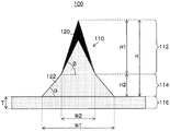
The transdermal absorption sheet 100 is attached to the skin to deliver a drug into the skin. As shown in fig. 1, the percutaneous absorption sheet 100 has a tapered needle portion 112, a truncated cone portion 114 connected to the needle portion 112, and a sheet-like sheet portion 116 connected to the truncated cone portion 114. The needle-like convex portion 110 is constituted by a tapered needle portion 112 and a tapered portion 114. The sheet shape is a shape in which the thickness is small relative to two opposing main surfaces (the 1 st main surface and the 2 nd main surface) having a large area and the whole is flat, and it is not necessary that the main surfaces are completely flat.
A plurality of tapered portions 114 (only one tapered portion 114 is shown in fig. 1) are formed on the surface of the sheet portion 116. The frustum portion 114 has two bottom surfaces, and has a three-dimensional configuration surrounded by a conical surface. Of the two bottom surfaces of the frustum portion 114, the bottom surface (lower base) having a larger area is connected to the sheet portion 116. Of the two bottom surfaces of the tapered portion 114, the bottom surface (upper bottom) having a smaller area is connected to the needle portion 112. That is, of the two bottom surfaces of the frustum portion 114, the area of the bottom surface in the direction away from the sheet portion 116 becomes smaller.
The needle portion 112 has a tapered shape, and the needle portion 112 has a bottom surface with a large area and a shape in which the tip end distant from the bottom surface has a minimum area. Since the bottom surface of the needle portion 112 having a large area is connected to the bottom surface of the frustum portion 114 having a small area, the needle portion 112 has a shape tapered toward the direction away from the frustum portion 114. Therefore, the needle-like convex portion 110 composed of the needle portion 112 and the tapered portion 114 has a shape tapered toward the tip from the sheet portion 116 as a whole. A plurality of 4-2500 needle-like protrusions 110 are provided on the sheet portion 116. However, the number is not limited to this number.
In fig. 1, the truncated cone portion 114 has a truncated cone shape, and the needle portion 112 has a conical shape. The shape of the tip of the needle portion 112 can be appropriately changed to a curved surface having a radius of curvature of 0.01 μm to 50 μm, a flat surface, or the like, depending on the degree of insertion of the needle portion 112 into the skin.
Fig. 2 shows a needle-like projection 110 having another shape. In fig. 2, the frustum portion 114 has a square frustum shape, and the needle portion 112 has a square pyramid shape.
Fig. 3 is a sectional view of the percutaneous absorption sheet 100 shown in fig. 1 and 2. Fig. 3 shows, as an example, a case where the percutaneous absorption sheet 100 is composed of a1 st layer 120 containing a drug and a 2 nd layer 122 not containing a drug. The 2 nd layer 122 may contain a drug, or only the 1 st layer may constitute a needle portion.
The thickness T of the sheet portion 116 is preferably in the range of 10 μm to 2000 μm, and more preferably in the range of 10 μm to 1000 μm. The width W1 of the bottom surface (lower bottom) of the tapered portion 114 in contact with the sheet portion 116 is preferably in the range of 100 to 1500 μm, and more preferably in the range of 100 to 1000 μm. The width W2 of the bottom surface (upper surface) of the tapered portion 114 in contact with the needle portion 112 is preferably in the range of 100 to 1500 μm, more preferably in the range of 100 to 1000 μm. The width W1 and the width W2 preferably satisfy W1> W2 within the above numerical range.
The height H of the needle-like projections 110 is preferably in the range of 100 to 2000. mu.m, more preferably in the range of 200 to 1500. mu.m. Further, the ratio of the height H1 of the needle portion 112 to the height H2 of the frustum portion 114, that is, H1/H2, is preferably in the range of 1 to 10, and more preferably in the range of 1.5 to 8. The height H2 of the truncated cone portion 114 is preferably in the range of 10 μm to 1000. mu.m.
The angle α formed by the inclined surface of the tapered portion 114 and the surface parallel to the surface of the sheet portion 116 is preferably in the range of 10 ° to 60 °, and more preferably in the range of 20 ° to 50 °. The angle β formed by the inclined surface of the needle portion 112 and the surface parallel to the upper bottom of the frustum portion 114 is preferably in the range of 45 ° to 85 °, and more preferably in the range of 60 ° to 80 °.
The angle β may be equal to the angle α, but it is preferred that the angle β is larger than the angle α. This is to facilitate the penetration of the needle-like projection 110 into the skin.
In the present embodiment, the percutaneous absorbent sheet 100 having the needle-like protrusions 110 shown in fig. 1 and 2 is shown, but the percutaneous absorbent sheet 100 is not limited to these shapes.
Fig. 4 is an overall perspective view of the percutaneous absorption sheet. As shown in fig. 4, the percutaneous absorption sheet 100 is composed of a sheet portion 116 having a1 st main surface and a 2 nd main surface, and a plurality of needle-like projections 110 arranged on the 1 st main surface of the sheet portion 116. The sheet portion 116 includes an end portion 116C, a central portion 116A that is a region where the plurality of needle-like protrusions 110 are arranged, and an outer edge portion 116B that is a region from the central portion 116A to the end portion 116C. The sheet portion 116 is divided into a shape in a plan view by the end portion 116C. The sheet portion 116 in fig. 4 is rectangular in a plan view, but may be polygonal, circular, oval, or the like. The shape of the sheet portion 116 is not limited as long as the sheet portion can include a central portion 116A in which the plurality of needle-like protrusions 110 can be arranged and an outer edge portion 116B. The percutaneous absorption sheet 100 of the present embodiment has a thickness portion 116D at the outer edge portion 116B. The thickness portion 116D is a portion where the film thickness is thick in the outer edge portion 116B of the sheet portion 116.
The needle-like protrusions 110 are portions protruding from the sheet portion 116, and the needle-like protrusions 110 can be identified by defining a virtual auxiliary surface that contacts the 1 st main surface of the sheet portion 116.
Next, preferred embodiments of the mold 13 used for performing the chemical liquid filling step in the method for producing a percutaneous absorption sheet of the present invention and the liquid filling device 10 for filling the mold 13 with the chemical liquid will be described.
[ mold ]
Fig. 5 is a process diagram showing the production of the mold (mold) 13.
As shown in fig. 5(a), initially, a base plate for making a mold 13 is prepared, and the mold 13 is used for manufacturing a percutaneous absorption sheet.
There are two methods for manufacturing the base plate 11, and in the 1 st method, a photoresist is applied to a Si substrate, and then exposure and development are performed. Next, a plurality of projections 12 having the same shape as the needle-like projections 110 of the percutaneous absorption sheet are formed in an array on the surface of the base plate 11 by Etching such as RIE (Reactive Ion Etching). In addition, when etching such as RIE is performed to form the convex portion 12 on the surface of the base plate 11, the Si substrate may be obliquely etched while being rotated.
The 2 nd method is as follows: a metal substrate made of stainless steel, aluminum alloy, Ni, or the like is processed using a cutting tool such as a diamond cutter, whereby a plurality of projections 12 are formed in an array on the surface of the base plate 11.
Next, as shown in fig. 5(B), a mold 13 is produced using the bottom plate 11. In the production of the normal mold 13, a method such as Ni electroforming is used. Since the bottom plate 11 has the conical or pyramidal (for example, square pyramid) convex portion 12 whose tip is an acute angle, 4 methods are conceivable in which the shape is accurately transferred to the mold 13, the mold 13 can be peeled off from the bottom plate 11, and the manufacturing can be performed at low cost.
The first method is a method in which a silicone resin (silicone resin) obtained by adding a curing agent to PDMS (polydimethylsiloxane), for example, silicone rubber 184(sylgard 184) manufactured by Dow Corning corporation, is poured into a base plate 11, and the base plate 11 is heat-treated at 100 ℃ to be cured, and then a mold 13 is peeled off from the base plate 11. The 2 nd method is a method in which an ultraviolet-curing resin cured by irradiation with ultraviolet rays is poured into the base plate 11, ultraviolet rays are irradiated in a nitrogen atmosphere, and then the mold 13 is peeled from the base plate 11. The 3 rd method is a method in which a substance obtained by dissolving a plastic resin such as polystyrene or PMMA (polymethyl methacrylate) in an organic solvent is poured into a base plate 11 coated with a release agent, and after the organic solvent is volatilized and hardened by drying, a mold 13 is released from the base plate 11. The 4 th method is a method of producing an inverted product by Ni electroforming.
Thus, the mold 13 having the needle-like recesses 15, which are the inverse shape of the projections 12 of the bottom plate 11, arranged in 2 dimensions is manufactured. Fig. 5(C) shows the mold 13 thus produced. Since the projections 12 of the base plate 11 have the same shape as the needle-like projections 110 of the percutaneous absorption sheet, as shown in fig. 5(C), a mold 13 having a plurality of needle-like recesses 15 as a reverse mold of the needle-like projections 110 of the percutaneous absorption sheet is produced. In any of the 4 methods described above, the mold 13 can be easily manufactured a plurality of times.
Fig. 6 is a diagram showing a more preferable form of the mold composite 18 in terms of the method for producing the percutaneous absorption sheet. As shown in fig. 6, the mold assembly 18 includes a mold 13 having a through hole 15C formed at the tip of the needle-like recess 15, and a gas-permeable sheet 19 bonded to the side of the through hole 15C of the mold 13 and made of a material that is gas-permeable and liquid-impermeable. The tip of the needle-like recess 15 is communicated with the atmosphere through the gas permeable sheet 19 by the through hole 15C. The tip of the needle-like recess 15 is a side tapered in the depth direction of the die 13, and is opposite to a side filled with a chemical liquid that is a solution containing a chemical and a base liquid that is a solution not containing a chemical.
By using such a mold complex 18, only air present in the needle-like recesses 15 can be passed through the through-holes 15C from the needle-like recesses 15 without passing through the percutaneous absorbent material solution (solution) filled in the needle-like recesses 15. The shape of the needle-like recesses 15 can be transferred to the percutaneous absorption material with improved transferability, and sharp needle-like projections can be formed.
The diameter D (diameter) of the through hole 15C is preferably in the range of 1 to 50 μm. By setting the range, the permeation of air is facilitated, and the distal end portion of the needle-like projection 110 of the percutaneous absorption sheet can be formed into a sharp shape. For example, ポアフロン (registered trademark, trade name of porous material using 100% PTFE manufactured by sumitomo electrical industries co., ltd.) can be suitably used as the gas-permeable sheet 19 made of a material that is gas-permeable and liquid-impermeable.
As described above, the through-hole 15C is opened in the mold 13 in order to improve the filling property and the peeling property of the chemical solution 22, and the present invention can be applied to the liquid filling step regardless of the presence or absence of the through-hole 15C in the mold 13.
As the material used for the mold 13, an elastic material or a metal material can be used. Among these, an elastic material is preferable, and a material having high gas permeability is more preferable.
Oxygen permeability, which is a typical gas permeability, is preferably 1X 10-12(mL/s.m.Pa) is larger, and more preferably larger than 1X 10⁻¹⁰(mL/s. m.Pa) is large. By forming the mold 13 of a material having high gas permeability, the solution containing the drug can be sucked by suction from the back surface of the mold 13, and the filling of the needle-like recess 15 with the solution can be promoted. Further, the air existing in the needle-like recesses 15 of the mold 13 can be expelled from the mold 13 side. The percutaneous absorption sheet with less defects can be manufactured.
Specific examples of such a material include materials obtained by melting or dissolving a common engineering plastic such as a silicone resin (e.g., silicone rubber 184 (registered trademark) manufactured by dow corning corporation, 1310ST (product number) manufactured by shin-Etsu chemical industries), an ultraviolet curable resin, a polystyrene resin, PMMA (polymethyl methacrylate), an epoxy resin, a PET resin (polyethylene terephthalate), a POM resin (polyoxymethylene), a teflon (registered trademark) resin (polytetrafluoroethylene), a PS resin (polystyrene), a PE resin (polyethylene), a phenol resin, and a urethane resin in a solvent.
Among them, the silicone rubber-based material is suitably used because it has durability against transfer by repeated pressurization and has good releasability from the material.
Examples of the metal material include Ni, Cu, Cr, Mo, W, Ir, Tr, Fe, Co, MgO, Ti, Zr, Hf, V, Nb, Ta, α -alumina, zirconia, stainless Steel (STAVAX), and alloys thereof. As the material of the frame 14, the same material as that of the mold 13 can be used.
(agent)
The drug contained in the dissolution solution as the liquid to be filled into the needle-like recess 15 is not particularly limited as long as it is a substance having physiological activity. The drug is preferably selected from peptides, proteins, nucleic acids, polysaccharides, vaccines, pharmaceutical compounds, and cosmetic ingredients. Furthermore, the pharmaceutical compound is preferably a water-soluble low-molecular compound. Here, the low-molecular compound is a compound having a molecular weight in the range of several hundreds to several thousands.
The water-soluble polymer substance contained in the layer containing the drug is preferably a substance that does not interact with the drug contained in the layer. For example, in the case of using protein as a drug, when a charged polymer substance is mixed, the protein and the polymer substance form aggregates by electrostatic interaction, and the aggregates are aggregated and precipitated. Therefore, when a substance having a charge is used as a drug, a water-soluble polymer substance having no charge, such as hydroxyethyl starch or dextran, is preferably used.
[ liquid filling apparatus ]
Fig. 7 is a schematic diagram showing an example of the overall configuration of the liquid filling apparatus 10.
As shown in fig. 7, the liquid filling apparatus 10 is constituted by, as a basic structure: a liquid supply device 36 having a liquid feed tank 30 for storing a liquid chemical and a nozzle 34 attached to the liquid feed tank 30; a Z-axis drive unit 50 for moving the liquid supply device 36 up and down (Z-axis direction), a suction table 52 (base) for placing and fixing the mold 13, a load cell 53 for measuring a pressing force for pressing the nozzle tip of the nozzle against the surface of the mold 13, an X-axis drive unit 54 for driving the suction table 52 in the X-axis direction, which is the relative movement direction of the nozzle 34, a stand 56 for supporting the device, and a control system 58 for controlling the entire liquid filling device 10.
The liquid-feeding tank 30 is disposed above the slider 46 driven in the vertical direction of the Z-axis driving unit 50, and a discharge device 48 for pressurizing the inside of the liquid-feeding tank 30 and supplying the chemical solution 22 to the nozzle 34 is provided above the liquid-feeding tank 30. The liquid-feeding tank 30 and the discharge device 48 are supported by 3 brackets 47 supported by the slider 46.
A slit portion 34E communicating with the opening portion 34B is formed inside the nozzle 34, and a supply port (not shown) of the slit portion 34E and the liquid-feed tank 30 are connected by a pressure-resistant hose 32.
In the present embodiment, a case where the nozzle 34 moves relative to the mold 13 fixed by the X-axis driving unit 54 will be described. The direction of the arrow (X-axis direction) in which the nozzle 34 of fig. 7 moves is referred to as a filling movement direction.
In fig. 7, the entire liquid supply device 36 including the liquid feed tank 30 and the nozzle 34 is driven in the vertical direction by the Z-axis drive unit 50, but the vertical drive of the liquid feed tank 30 is not essential, and only the nozzle 34 may be driven by the Z-axis drive unit 50.
Fig. 8 is a schematic perspective view of the nozzle 34. As shown in fig. 8, the nozzle 34 has a nozzle tip 35 composed of a downstream nozzle tip 35A and an upstream tip 35B. Further, the nozzle tip portion 35 has a notch surface 34A as a flat surface formed to face the surface of the mold 13, and has two inclined surfaces 34C and 34D extending in a direction away from the notch surface 34A. Of the two inclined surfaces 34C and 34D, the inclined surface on the downstream side as viewed in the nozzle movement direction is referred to as a downstream-side inclined surface 34C, and the inclined surface on the upstream side is referred to as an upstream-side inclined surface 34D. The slit surface 34A is formed with a slit-shaped opening 34B for discharging the chemical solution 22. When viewed by relative movement between the nozzle 34 and the needle-like recess 15, the upstream side refers to a direction in which the needle-like recess 15 to be filled approaches the nozzle 34, and the downstream side refers to a direction in which the needle-like recess 15 to be filled separates from the nozzle 34.
The slit-shaped openings 34B allow the plurality of needle-like recesses 15 constituting 1 row to be simultaneously filled with the chemical solution 22, for example. The length of the opening 34B in the nozzle width direction and the width of the opening 34B (the gap between the openings) are appropriately selected in accordance with the number of needle-like recesses 15 to be filled at a time.
By making the length of the opening 34B longer, more needle-like recesses 15 can be filled with the chemical liquid 22 at a time. This can improve productivity.
As the material used for the nozzle 34, an elastic material or a metal material can be used. Examples thereof include teflon (registered trademark), polyacetal, polyethylene, stainless steel (SUS), titanium, and the like. In order to suppress contamination due to the adhesion of the chemical solution to the nozzle, the nozzle surface is preferably coated with a hydrophobic or non-adhesive coating. In particular, the downstream inclined surface 34C of the downstream nozzle tip 35A is coated with a hydrophobic or non-adhesive coating, whereby the wetting of the chemical solution during filling can be suppressed.
It is preferable that the inner wall surface of the slit portion 34E is coated with a hydrophilic coating so that the chemical solution 22 is uniformly spread in the nozzle width direction during filling.
Then, in order to fill the needle-like recess 15 of the mold 13 with the chemical solution 22 through the nozzle 34, the nozzle 34 is moved closer to the mold 13 by the Z-axis drive unit 50 until the pressing force from the nozzle 34 to the surface of the mold 13 becomes the Z-coordinate of the desired pressing force. Whether or not the pressing force is a desired pressing force is confirmed by the load cell 53.
Then, while the nozzle 34 in contact with the mold 13 is scanned in the arrow direction by the X-axis drive unit 54, the chemical liquid 22 is discharged from the opening 34B when the nozzle tip 35 of the nozzle 34 is positioned above the needle-like recess 15. Thereby, the needle-like recess 15 of the mold 13 is filled with the chemical liquid 22 from the nozzle 34. In this case, the method includes both a method of filling the needle-shaped recess 15 with the chemical solution 22 while continuously moving the nozzle 34 and an intermittent movement method of temporarily stopping the nozzle 34 above the needle-shaped recess 15 during the movement of the nozzle 34, filling the needle-shaped recess 15 with the chemical solution 22, and then moving the nozzle 34 again. In either case, however, the nozzle tip 35 of the nozzle 34 is in contact with the surface of the mold 13.
In addition to the basic configuration described above, the liquid filling device 10 used in the method for producing a percutaneous absorption sheet of the present invention also has a Z-axis drive unit 50 for holding the nozzle 34 via the elastic body 42 and moving the nozzle 34 up and down. Thereby, the elastic body 42 absorbs the variation in the pressing force of the nozzle 34 against the surface of the mold 13.
The elastic body 42 may be any structure having a restoring force that deforms when a force is applied and returns to its original shape when the force is released. However, a structure having an elastic force with respect to the translational movement in the thickness direction of the mold 13, and a structure having an elastic force with respect to the in-plane rotational movement (mainly the rotational movement on the horizontal plane) including the relative movement direction of the nozzle 34 and the mold 13 can be suitably used.
As the elastic body 42 having an elastic force against the translational movement in the thickness direction of the mold 13, a coil spring 42A, another extension spring, a disc spring, a resin having an elastic force, an air spring, or an elastic body 42 combining these can be used.
Further, as the elastic body 42 having an elastic force for the translational movement in the thickness direction of the mold 13 and an elastic force for the in-plane rotational movement including the relative movement direction of the nozzle 34 and the mold 13, a plate spring 42B can be used, and further, a torsion spring, a resin spring, and an elastic body 42 combining these can be used.
If the force acts as a restoring force in the opposite direction to the increase/decrease of the pressing displacement amount to the die 13 regardless of the elastic force, vibration, buoyancy, or the like of the vibrator using gravity may be used in order to perform the same function as the elastic force of the elastic body.
The elastic body 42 needs to absorb variation in the pressing force of the nozzle 34 against the surface of the mold 13, and to eliminate variation in the amount of deformation of the needle-like recess 15 of the mold 13. Therefore, the elastic body 42 is preferably made of a material softer than the mold 13, or the total elastic constant (spring constant in the case of a spring) of the number of elastic bodies 42 interposed between the Z-axis driving section 50 and the nozzle 34 is preferably smaller than the hardness or elastic constant of the mold 13.
However, making the elastic constant of the elastic body 42 used in the nozzle pressing direction smaller (softer) (in the case where the elastic body is a spring), tends to make the elastic constant softer in the width direction of the nozzle 34 and in the filling movement direction. In this case, by pressing the nozzle 34 against the mold 13, the nozzle 34 is likely to be rotated in the horizontal plane by the elastic body 42, and the nozzle 34 is likely to have an excessive fluctuation component in the width direction and the filling moving direction of the nozzle 34, which is a factor that is not good for the filling accuracy of the needle-like recess 15 with the chemical solution 22.
As a countermeasure, it is preferable to further include a guide mechanism 44 that restricts the movable range of the nozzle 34 in the moving direction.
In this case, by combining the elastic body 42, which exhibits an elastic force in the translational direction in the mold thickness direction like the coil spring 42A, with the guide mechanism 44, it is possible to prevent the occurrence of the above-described bad factors and to construct the nozzle holding portion in a space-saving manner.
In addition, in the case of using the elastic body 42 having an elastic force in the translational direction in the mold thickness direction and an elastic force in the in-plane rotational movement like the plate spring 42B, since the above-described unfavorable factors can be suppressed, it is not necessary to provide the guide mechanism 44.
On the other hand, since the elastic body 42 having an elastic force only in the thickness direction of the mold 13 like the coil spring 42A performs a translational motion in the thickness direction of the mold 13, the posture of the nozzle 34 does not change, the geometrical relationship between the mold 13 and the nozzle 34 is less affected, and there is an advantage in mounting the measuring instruments and the accessories around the filling and filling to the nozzle side.
Therefore, it is preferable to appropriately select whether to use the elastic body 42 having the elastic force in the translational direction in the thickness direction of the mold 13 or to use the elastic body 42 having the elastic force in the translational direction in the thickness direction of the mold 13 and having the elastic force in the in-plane rotational movement. Further, although the embodiment in which the elastic body 42 is directly or indirectly connected to the nozzle 34 has been described, the position in which the elastic body 42 is provided is not limited to this embodiment. For example, if the elastic body 42 is provided on the suction table 52 on which the mold 13 is placed, the same effect can be obtained.
The liquid filling apparatus 10 of fig. 7 uses a coil spring 42A as the elastic body 42, and further includes a guide mechanism 44 for guiding the vertical movement of the nozzle 34.
That is, a rectangular upper plate 51 supported by the slider 46 in a horizontally cantilevered manner is provided below the slider 46, and the upper end of the coil spring 42A is fixed to the lower surface of the upper plate 51. The lower end of the coil spring 42A is fixed to a rectangular lower plate 55 fixed to the horizontal top surface of the nozzle 34. That is, the nozzle 34 is suspended from the upper plate 51 moved up and down by the Z-axis drive unit 50 via the coil spring 42A and the lower plate 55.
When the coil spring 42A is interposed between the Z-axis drive unit 50 and the nozzle 34, the nozzle 34 may not be fixed to the Z-axis drive unit 50 in a fixed posture only by the coil spring 42A, and the posture of the nozzle 34 may be inclined or shifted in the front, rear, left, and right directions other than the pressing direction. As a result, the pressing angle at which the nozzle 34 presses the surface of the mold 13 may vary, the volume of each needle-like recess 15 may vary, and the filling amount of each needle-like recess 15 may vary. Therefore, when the coil spring 42A is used as the elastic body 42, the guide mechanism 44 is preferably further provided.
The guide mechanism 44 is constituted by: the upper portions of the guide rods 57 are inserted and fixed into 4 holes bored at 4 corners of the upper plate 51, respectively, and the lower end portions of the respective guide rods 57 are inserted into 4 holes 59 bored at 4 corners of the lower plate 55 in a non-fixed state. In this case, the 4 guide rods 57 are disposed parallel to the vertical movement direction of the nozzle 34, that is, the pressing direction of the nozzle 34. Thereby, the nozzle 34 is moved up and down only in the pressing direction by the guide mechanism 44. Therefore, even if the coil spring 42A is used as the elastic body 42, the pressing angle of the nozzle 34 against the mold 13 can be made constant.
In this way, when a reaction force in the direction opposite to the pressing direction acts on the nozzle 34 by holding the nozzle 34 via the coil spring 42A by the Z-axis driving section 50 that moves the nozzle 34 up and down, the coil spring 42A contracts in the direction opposite to the pressing direction in accordance with the magnitude of the reaction force. Thereby, the coil spring 42A absorbs variation in pressing force that varies due to factors such as variation in thickness of the mold, and a pressing displacement amount by which the nozzle tip 35 of the nozzle 34 presses the surface of the mold 13. As a result, the volume of each of the needle-like recesses 15 arranged is less likely to change, and therefore variation in the filling amount of each of the needle-like recesses 15 is less likely to occur. When the coil spring 42A is used as the elastic body 42, it is more preferable to provide a guide mechanism 44 for guiding the vertical movement of the nozzle 34. This also makes the pressing angle constant, and therefore the variation in the pressing force due to the variation in the pressing angle also disappears.
Further, by absorbing the variation in the pressing force to the mold 13 by the coil spring 42A, the situation where a large hydraulic pressure is locally applied to the contact portion S (see fig. 7 and 12) where the nozzle tip portion 35 is pressed against the surface of the mold 13 and contacted is eliminated. Therefore, the conventional problem that the chemical liquid 22 leaks outward from the contact portion S where a large hydraulic pressure acts is eliminated, and therefore, the chemical liquid 22 containing an expensive chemical is less likely to adhere to the flat surface portion 13A of the mold 13 other than the needle-like recess 15 even during high-speed filling.
The liquid filling apparatus 10 of fig. 9 uses a plate spring 42B as the elastic body 42. Note that the same components as those described in fig. 7 are assigned the same reference numerals, and description thereof is omitted.
As shown in fig. 9, a rectangular plate spring 42B horizontally supported by the slider 46 in a cantilever manner is provided below the slider 46 driven in the vertical direction by the Z-axis driving unit 50. The top surface of the nozzle 34 is fixed to the lower surface of the tip end (the filling movement direction side) of the plate spring 42B.
In this way, when the plate spring 42B is used as the elastic body 42, if a reaction force in the direction opposite to the pressing direction acts on the nozzle 34, the plate spring 42B warps according to the magnitude of the reaction force. Thus, the plate spring 42B absorbs variations in the amount of pressing displacement by which the nozzle tip 35 of the nozzle 34 presses the surface of the mold 13, variations in the thickness of the mold, and variations in the pressing force that varies depending on the pressing angle. Therefore, the volume of each of the needle-like recesses 15 arranged is less likely to change, and therefore variation in the filling amount of each of the needle-like recesses 15 is less likely to occur.
This can improve the filling accuracy of the chemical solution 22 in each of the aligned needle-like recesses 15, and can effectively prevent the chemical solution 22 containing an expensive chemical from adhering to the flat surface portion 13A of the mold 13 even at the time of high-speed filling.
In particular, when the plate spring 42B is used as the elastic body 42, the nozzle 34 can be fixed to the Z-axis driving unit 50 only by the elastic body 42. Thus, the guide mechanism 44 having a sliding portion (dust generation by the rubbing of the guide rod 57 and the hole 59 of the lower plate 55 in fig. 7) is not required, and there is no fear that dust is generated and dust is mixed into the needle-like recess 15.
The elastic constant of the elastic body 42 used (spring constant in the case where the elastic body is a spring) is preferably softer than that of the mold 13, but if the elastic body is too soft, the nozzle 34 vibrates when the thickness of the portion other than the needle-like recess 15 fluctuates sharply, and there is a possibility that the mold 13 is damaged or unnecessary leakage from the nozzle 34 occurs. Examples of the rapid thickness variation include a bonding level difference generated when a plurality of molds 13 are bonded with an adhesive, fusion, or the like, and a foreign matter level difference due to a foreign matter mixed into the molds 13 and adhering thereto.
In order to avoid such a problem of vibration, it is preferable to interpose a viscous body (not shown) between the Z-axis driving unit 50 that moves the nozzle 34 up and down and the nozzle 34. In this case, it is more preferable that the viscous body be interposed in parallel with the elastic body 42, because the vibration can be more easily damped than that in series with the elastic body 42.
As the viscous body, for example, a damper (shockabsorber) in which a liquid or a gas is sealed in a rubber tape, a polymer material having a viscous force, or the like can be suitably used.
In this way, by interposing a viscous body between the nozzle 34 and the Z-axis driving portion 50 that moves the nozzle 34 up and down, even if there is the above-described joining level difference or foreign matter level difference, it is possible to enhance the tolerance against variation in the pressing force of the nozzle 34.
This makes it difficult for the nozzle position to fluctuate even with a sudden thickness fluctuation, and also makes it possible to further improve the filling accuracy because the attenuation of the vibration caused by the fluctuation is large.
Next, a method for producing the transdermal absorption sheet of the present embodiment will be described.
(method for producing percutaneous absorption sheet)
In the method for producing a percutaneous absorption sheet of the present embodiment, after the device preparation step for preparing the mold 13 and the liquid filling device 10, at least 5 steps of a chemical liquid filling step, a chemical liquid drying step, a base material liquid filling step, a base material liquid drying step, and a peeling step are sequentially performed as shown in fig. 10.
(liquid medicine filling step)
Fig. 11 illustrates a basic process of filling the aligned needle-like recesses 15 with the chemical solution 22 by repeating a filling operation of supplying the chemical solution 22 from the liquid supply device 36 to the mold 13 and filling 1 or more needle-like recesses 15 with the chemical solution 22 in a state where the nozzle tip 35 of the nozzle 34 positioned above the needle-like recess 15 is pressed against and brought into contact with the surface of the mold 13 and a moving operation of relatively moving the nozzle 34 with respect to the mold 13 in a state where the nozzle tip 35 is brought into contact with the surface of the mold 13.
Therefore, in fig. 11, the respective improvements of the elastic body 42 (coil spring, leaf spring, etc.), the guide mechanism 44, etc., which have been described in the liquid filling apparatus 10, are not shown.
As shown in fig. 11(a), a mold 13 having aligned needle-like recesses 15 is disposed on a base 20. The mold 13 has two sets of a plurality of needle-like recesses 15 arranged in a 5 × 5 array. A liquid supply device 36 is prepared, and the liquid supply device 36 has a liquid feed tank 30 for storing the chemical liquid 22, a pressure-resistant hose 32 connected to the liquid feed tank 30, and a nozzle 34 connected to the tip of the pressure-resistant hose 32. The chemical liquid 22 is discharged from the tip of the nozzle 34.
The filling step is described with reference to fig. 11 (B). As shown in fig. 11(B), the position of the opening 34B of the nozzle 34 is adjusted to be above the needle-like recess 15. Since the nozzle 34 for discharging the chemical solution 22 is pressed against the mold 13, the cut surface 34A of the nozzle 34 is in contact with the surface of the mold 13. The chemical liquid 22 is supplied from the liquid supply device 36 to the mold 13, and the chemical liquid 22 is filled into the needle-like recess 15 from the opening 34B of the nozzle 34. In the present embodiment, the needle-like recesses 15 constituting 1 row are simultaneously filled with the chemical solution 22. However, the present invention is not limited to this, and the needle-like recesses 15 may be filled one by one.
When the mold 13 is made of a material having gas permeability, the chemical liquid 22 can be sucked by sucking from the back surface of the mold 13, and the filling of the chemical liquid 22 into the needle-like recess 15 can be facilitated.
Next, in the filling step of fig. 11(B), as shown in fig. 11(C), the liquid supply device 36 is relatively scanned in the filling movement direction of the opening 34B while the nozzle tip of the nozzle 34 is brought into contact with the surface of the mold 13. The nozzle 34 is moved to the needle-like recess 15 not filled with the chemical liquid 22 by scanning the nozzle 34 over the mold 13. The opening 34B of the nozzle 34 is positioned above the needle-like recess 15. In the present embodiment, the example in which the nozzle 34 is scanned is described, but the mold 13 may be scanned.
By repeating the filling operation in fig. 11(B) and the moving operation in fig. 11(C), the needle-like recesses 15 arranged 5 × 5 are filled with the chemical solution 22. When the needle-like recesses 15 arranged 5 × 5 are filled with the chemical liquid 22, the liquid supply device 36 is moved to the adjacent needle-like recesses 15 arranged 5 × 5, and the filling operation in fig. 11(B) and the moving operation in fig. 11(C) are repeated. The needle-like recesses 15 arranged adjacently by 5 × 5 are also filled with the chemical solution 22.
When the filling of the chemical solution 22 into the needle-like recessed portion 15 is completed and the nozzle 34 is lifted from the surface of the mold 13, it is preferable to suck the chemical solution 22 adhering to the nozzle tip portion 35 by making the pressure inside the liquid-feeding tank 30 or the nozzle 34 negative with respect to the atmospheric pressure. This can further suppress the adhesion of the chemical solution to the flat surface portion other than the needle-like recess 15, and can stabilize the liquid surface at the next filling, thereby improving the filling accuracy.
In the chemical liquid filling step, the chemical liquid 22 can be filled into the needle-like recess 15 by sucking the chemical liquid from the side of the through hole 15C by the mold composite 18 shown in fig. 6. This is because, in particular, if air bubbles are taken into the drug solution 22, the content of the drug varies, which is not preferable.
The filling operation of fig. 12 and the moving operation of fig. 13 are for explaining the operation of the elastic body 42.
As shown in fig. 12 and 13, the nozzle 34 is held by a Z-axis drive unit 50 that moves the nozzle 34 up and down via an elastic body 42 in order to press and contact the nozzle tip 35 against the surface of the mold 13. The elastic body 42 absorbs the variation in the pressing force of the nozzle 34 against the mold 13. That is, by interposing the elastic body 42 between the Z-axis driving portion 50 that moves the nozzle 34 up and down and the nozzle 34 to hold the nozzle 34, it is possible to manufacture a sheet while absorbing, with the elastic body 42, a variation in pressing force against the mold 13 when the nozzle tip portion 35 is pressed against and brought into contact with the surface of the mold 13. Fig. 12 and 13 illustrate a case where a coil spring 42A is used as the elastic body 42.
This allows the elastic body 42 to absorb variations in the pressing displacement of the nozzle tip 35 against the surface of the mold 13, variations in the thickness of the mold 13, and variations in the pressing force of the nozzle 34 due to the pressing angle, and the like, thereby keeping the pressing force constant. As a result, the filling accuracy of the chemical solution 22 in the respective needle-like recesses 15 arranged can be improved.
After the chemical solution filling step shown in fig. 14(a) is completed, the chemical solution drying step and the filling steps after the 2 nd layer are repeated as necessary for the needle shape to be formed, and then the process proceeds to the peeling step. For example, as shown in fig. 14(B) to 14(D), a chemical liquid drying step of drying and solidifying the chemical liquid 22 to form the 1 st layer 120 containing the chemical agent in the needle-like recess 15, a base liquid filling step of applying the base liquid 24 containing no chemical agent on the 1 st layer 120 containing the chemical agent to fill the base liquid 24 into the needle-like recess 15, and a base liquid drying step of drying and solidifying the base liquid 24 to form the 2 nd layer 122 are performed, and then the process proceeds to the peeling step of fig. 15 or 16. Reference numeral 40 in fig. 15 or 16 denotes a sheet-like base material for peeling the manufactured percutaneous absorption sheet from the mold 13, on which an adhesive layer is formed.
The present invention will be described more specifically below with reference to examples of the present invention. The materials, amounts used, ratios, processing contents, processing procedures and the like shown in the following examples can be appropriately changed without departing from the gist of the present invention. Therefore, the scope of the present invention should not be construed as being limited to the specific examples shown below.
[ examples ]
[ test A ]
In test a, the filling accuracy was compared between the case where the needle-shaped recess 15 of the mold 13 was filled with the chemical solution 22 using the liquid filling apparatus 10 in which the nozzle 34 was held by the Z-axis drive unit 50 via the elastic body 42 (example 1) and the case where the needle-shaped recess 15 of the mold 13 was filled with the chemical solution 22 using the liquid filling apparatus in which the Z-axis drive unit 50 and the nozzle 34 were directly fixed without interposing the elastic body 42 therebetween (comparative example 1).
The filling accuracy was compared by comparing the variation in the filling amount of the chemical solution 22 filled into the needle-like recess 15 when the mold 13 manufactured by the method described below was filled with the chemical solution 22 by using the liquid filling apparatus 10 of example 1 and the liquid filling apparatus of comparative example 1.
The deviation of the filling amount is performed by repeating the filling operation 5 times.
The mold 13, preparation of the chemical liquid 22 and the base liquid 24 used in the test a, the configuration of the liquid filling apparatus in the example 1 and the comparative example 1, filling and drying of the chemical liquid 22, coating and drying of the base liquid 24, and peeling of the polymer sheet 1 are as follows.
(mold)
As shown in FIG. 17, projections 12 having a needle-like structure, each having a conical bottom 12A having a diameter D2 of 300 μm and a height H2 of 500 μm, formed on a conical frustum 12B having a diameter D1 of 500 μm and a height H1 of 150 μm on a smooth Ni plate having one side of 40mm, were ground at a pitch P of 1000 μm to form 2-dimensional arrays of 10 rows by 10 columns, thereby producing a base plate 11.
A film made of silicone rubber (SILASTIC-MDX 4-4210, manufactured by Dow Corning corporation) was formed on the base plate 11 to a thickness of 0.6mm, and the base plate 11 was thermally cured and peeled off with the conical tip portion protruding 50 μm from the film surface. Thus, a reversed product of silicone rubber having a through hole with a diameter of about 30 μm was produced.
The mold 13 was used as a portion of the silicone rubber reverse product, which was cut out except for the flat surface portion and had a side of 30mm, in which 10 columns × 10 rows of needle-like recesses were formed in the central portion. The wider opening of needle-like recess 15 was defined as the front surface (front surface) of mold 13, and the surface of through-hole (air outlet hole) having a diameter of 30 μm was defined as the back surface of mold 13.
(preparation of drug solution)
Human serum albumin (manufactured by Wako pure chemical industries, Ltd.) was added as a drug at 2 mass% to a liquid obtained by dissolving hydroxyethyl starch (manufactured by Fresenius Kabi Co.) in water and preparing an 8% aqueous solution, and a polymer solution containing the drug, namely drug solution 22, was prepared. After the liquid preparation, the mixture was exposed to a reduced pressure of 3kPa for 4 minutes to sufficiently degas the liquid.
(preparation of base liquid)
Chondroitin sulfate (manufactured by pill-feathered Nilang food Co., Ltd. (Japanese: マルハニチロ food Co., Ltd.)) was dissolved in water and the solution was adjusted to a 40% aqueous solution, and the resultant solution was used as a base solution which was a polymer solution containing no drug. After the liquid preparation, the mixture was exposed to a reduced pressure of 3kPa for 4 minutes to sufficiently degas the liquid.
(liquid filling apparatus)
The basic structure of the liquid filling apparatus includes: an X-axis drive unit 54 that controls relative position coordinates in a filling movement direction (X-axis direction) of the mold 13 and the nozzle 34, a Z-axis drive unit 50 that moves the nozzle 34 up and down with respect to the surface of the mold 13, a liquid supply device 36 (an ultra-low volume dispenser SMP-3 manufactured by martial arts corporation (kanji 12456 ンジニアリング)), a suction table 52 that fixes the mold 13, and a load cell 53 (LCX-a-500N manufactured by union electric industry (japanese) ) that measures a pushing force of the nozzle 34.
In example 1, the nozzle 34 is held by the Z-axis driving unit 50 via the plate spring 42B as the elastic body 42, and in comparative example 1, the Z-axis driving unit 50 and the nozzle 34 are directly fixed without interposing the elastic body 42.
In example 1, as the elastic body 42, a plate spring 42B having a thickness of 200 μm and a width of 3cm was disposed at the center position in the nozzle width direction, and the nozzle 34 was fixed to the plate spring 42B with the distance between the Z-axis driving section 50 and the nozzle 34 being 5 mm.
In both example 1 and comparative example 1, a gas permeable sheet 19(ポアフロン (registered trademark) FP-010 manufactured by sumitomo electrical corporation) having a side of 15mm was placed on a horizontal suction table 52, and a mold 13 was placed thereon so that the front surface (front surface) was upward. Next, the pressure is reduced from the back side of the mold 13 by a suction pressure of 90kPa (gauge pressure), and the gas permeable sheet 19 and the mold 13 are fixed to the suction table 52 by suction.
As the nozzle 34, a nozzle 34 having a basic structure as shown in fig. 8 is used. The nozzle 34 is made of SUS (stainless steel), and a slit-shaped opening 34B having a length of 12mm and a width of 0.2mm is formed in the center of a slit surface 34A having a length of 20mm and a width of 2 mm. The nozzle 34 is connected to the liquid-feed tank 30 through a pressure-resistant hose 32.
(method of filling liquid medicine and method of drying liquid medicine)
Next, in both example 1 and comparative example 1, 3mL of the chemical solution 22 containing the drug is filled in the liquid-feeding tank 30 and the nozzle 34. The nozzle 34 is adjusted so that the slit-shaped opening 34B is parallel to the 1 st row of the plurality of needle-like recesses 15 formed on the surface of the mold 13. The nozzle 34 was set at 0.14kgf/cm at a position spaced at intervals of 2mm in the direction opposite to the row 2 with respect to the row 1 direction2(1.4N/cm2) The pressure (pressing force) of (2) is pressed against the surface of the mold 13. The pressing force was confirmed by the dynamometer 53. While the nozzle 34 is pressed, the chemical solution 22 is discharged from the opening 34B at a discharge rate of 0.31. mu.L/sec for 10 seconds while the nozzle is moved in the filling movement direction at a movement rate of 1 mm/sec.
The movement of the nozzle 34 was stopped at a position spaced in the direction opposite to the 9 th row by 2mm intervals with respect to the 10 th row of the plurality of needle-like recesses 15 arranged, and the nozzle 34 was separated from the mold 13.
Next, after the chemical solution 22 filled in the mold 13 is dried and cured at a temperature of 20 ℃ and a relative humidity of 60% RH, the entire dried and cured product of the chemical solution 22 adhering to the surface flat portion 13A other than the needle-like recess 15 of the mold 13 is peeled off by an adhesive tape.
(base liquid filling step)
Next, the surface of the mold 13 after the chemical solution 22 is dried and cured is directly coated with a base material solution 24 by a dispenser, and then dried and cured for 12 hours to form a polymer sheet 1.
(peeling step)
Next, the polymer sheet 1 is peeled off from the mold 13, and a percutaneous absorption sheet is manufactured.
The obtained percutaneous absorption sheet and the adhesive tape were measured for the drug content by the following methods.
(measurement of drug content)
The formed percutaneous absorption sheet was completely redissolved in 3mL of water to prepare a redissolved solution. Then, the evans blue (evansblue) dye concentration of the prepared redissolution was measured by an absorptiometer (V670), and the filling amount of the chemical solution 22 was calculated from the relationship between the existing evans blue concentration (standard curve) and absorbance. In addition, the amount of the chemical solution 22 adhering to the flat surface portion 13A of the mold 13 other than the needle-like recess 15 is calculated by preparing a redissolved solution and measuring the redissolved solution with an absorption spectrophotometer.
(test results)
The test results are shown in the table of fig. 18. In fig. 18, the "holding method" refers to a method of holding the nozzle 34 in the Z-axis drive unit 50. The "number of repetitions" indicates the number of times of repeating the filling operation of filling the needle-like recess 15 of the mold 13 with the chemical solution 22 in a state where the nozzle 34 is pressed against the surface of the mold 13 by the Z-axis drive unit 50, and the trial and error was performed 5 times in both example 1 and comparative example 1. The filling amount into the needle-like recess 15 is calculated by the above-described measurement method.
As shown in fig. 18, in comparative example 1, the minimum filling amount was 2.60mg, the maximum filling amount was 3.55mg, and the variation width was 0.95mg, as a result of 5 trial and error.
On the other hand, as a result of 5 times of trial and error in example 1, the minimum filling amount was 2.82mg, the maximum filling amount was 3.21mg, and the variation width was 0.39mg, which was reduced to half or less of that in comparative example 1.
That is, as in example 1, by holding the nozzle 34 via the elastic body 42 on the Z-axis driving unit 50 that moves the nozzle 34 up and down to press and contact the nozzle tip portion 35 against the surface of the mold 13, the elastic body 42 absorbs variations in the pressing displacement amount of the nozzle tip portion 35 against the surface of the mold 13 and the pressing force of the nozzle 34 due to variations in the thickness of the mold, and the like, and can make the pressing force constant.
As a result, the filling accuracy of the chemical liquid 22 in each needle-like recess 15 can be improved.
Description of the reference symbols
1 a polymer sheet; 10 a liquid filling device; 11 a base plate; 12a convex portion; 13, a mould; 13A surface flat portion; 14, 14 frames; 15 a needle-like recess; 18 a mold composite; 19 a gas permeable sheet; 20, a base platform; 22, liquid medicine; 24 a base material liquid; 30 liquid feeding tank; 34a nozzle; 34A cut surface; 34B opening part; a 34E slit portion; 35a nozzle front end; 36 a liquid supply device; 42 an elastomer; a 42A coil spring; a 42B leaf spring; 44 a guide mechanism; 46 a slide block; 47 a bracket; 48 a discharge device; a 50Z-axis drive unit; 51, upper plate; 52 a suction stage; 53 force gauge; a 54X-axis drive unit; 55 a lower plate; 56 stand; 58 control the system; 59 holes; s contact part
Claims (10)
1. A method for producing a sheet having needle-like projections, characterized in that,
the disclosed device is provided with:
a device preparation step of preparing a mold having a needle-like recess and a filling device provided with a liquid supply device having a nozzle for discharging a liquid from a slit-like opening formed at a tip end of the nozzle; and
a liquid filling step of filling the needle-shaped recesses with the liquid by repeating a filling operation of supplying the liquid from the liquid supply device to the mold and filling 1 or more needle-shaped recesses with the liquid in a state where the nozzle tip end portion positioned above the needle-shaped recess is pressed against the surface of the mold and the nozzle tip end portion is in contact with the surface of the mold, and a moving operation of relatively moving the nozzle with respect to the mold in a state where the nozzle tip end portion is in contact with the surface of the mold;
in the liquid filling step, an elastic body is interposed between a Z-axis driving portion that moves the nozzle up and down and the nozzle to hold the nozzle, and the nozzle tip portion is pressed against the surface of the mold to bring the nozzle tip portion into contact with the surface of the mold.
2. The method of manufacturing a sheet according to claim 1,
a viscous body is further interposed between the Z-axis drive unit and the nozzle.
3. The method of manufacturing a sheet according to claim 2,
the elastic body and the adhesive body are interposed in parallel.
4. A method for producing a sheet material according to any one of claims 1 to 3,
the elastic body has an elastic force for a translational movement in the thickness direction of the mold.
5. The method of manufacturing a sheet according to claim 4,
the elastic body is a coil spring.
6. A method for producing a sheet material according to any one of claims 1 to 3,
the elastic body has an elastic force for a translational motion in a thickness direction of the mold and an elastic force for an in-plane rotational motion including a relative movement direction of the nozzle and the mold.
7. The method of manufacturing a sheet according to claim 6,
the elastic body is a plate spring.
8. A method for producing a sheet material according to any one of claims 1 to 3,
the nozzle unit further includes a guide mechanism for limiting a movable range of the nozzle in a moving direction.
9. A method for producing a sheet material according to any one of claims 1 to 3,
the sheet is a percutaneous absorption sheet having needle-like projections containing a drug.
10. A method for producing a sheet having needle-like projections, characterized in that,
the disclosed device is provided with:
a device preparation step of preparing a mold having a needle-like recess and a filling device provided with a liquid supply device having a nozzle for discharging a liquid from a slit-like opening formed at a tip end of the nozzle; and
a liquid filling step of filling the needle-shaped recesses with the liquid by repeating a filling operation of supplying the liquid from the liquid supply device to the mold and filling 1 or more needle-shaped recesses with the liquid in a state where the nozzle tip end portion positioned above the needle-shaped recess is pressed against the surface of the mold and the nozzle tip end portion is in contact with the surface of the mold, and a moving operation of relatively moving the nozzle with respect to the mold in a state where the nozzle tip end portion is in contact with the surface of the mold;
the mold is placed on a base having an elastic body;
in the liquid filling step, the nozzle tip is pressed against the surface of the mold by a Z-axis driving unit that moves the nozzle up and down, and the nozzle tip is brought into contact with the surface of the mold.
Applications Claiming Priority (2)
| Application Number | Priority Date | Filing Date | Title |
|---|---|---|---|
| JP2015211803A JP6517126B2 (en) | 2015-10-28 | 2015-10-28 | Sheet manufacturing method |
| JP2015-211803 | 2015-10-28 |
Publications (2)
| Publication Number | Publication Date |
|---|---|
| CN106964062A CN106964062A (en) | 2017-07-21 |
| CN106964062B true CN106964062B (en) | 2020-11-03 |
Family
ID=57345679
Family Applications (1)
| Application Number | Title | Priority Date | Filing Date |
|---|---|---|---|
| CN201610958649.3A Expired - Fee Related CN106964062B (en) | 2015-10-28 | 2016-10-28 | Method for producing sheet |
Country Status (5)
| Country | Link |
|---|---|
| US (1) | US10512765B2 (en) |
| EP (1) | EP3162526B1 (en) |
| JP (1) | JP6517126B2 (en) |
| KR (1) | KR20170049415A (en) |
| CN (1) | CN106964062B (en) |
Families Citing this family (6)
| Publication number | Priority date | Publication date | Assignee | Title |
|---|---|---|---|---|
| JPWO2019111959A1 (en) * | 2017-12-05 | 2020-12-17 | 古河電気工業株式会社 | Functional members and their manufacturing methods |
| CN111801135B (en) * | 2018-03-30 | 2023-06-27 | 富士胶片株式会社 | Method for manufacturing microneedle array |
| CN110625864A (en) * | 2019-10-24 | 2019-12-31 | 上海微创生命科技有限公司 | Microneedle preparation device and microneedle preparation method |
| CN113733606B (en) * | 2020-06-03 | 2022-11-18 | 河南泰田重工机械制造有限公司 | A mould pressing loading attachment for producing glass steel |
| DE102020131229A1 (en) * | 2020-11-25 | 2022-05-25 | Novem Car Interior Design Gmbh | Process for producing a molded part |
| TW202313306A (en) * | 2021-06-01 | 2023-04-01 | 波蘭商Xtpl股份有限公司 | Method of filling a microcavity with a polymer material, a filler in a microcavity, and an apparatus for filling a microcavity on or in a substrate with a polymer material |
Citations (4)
| Publication number | Priority date | Publication date | Assignee | Title |
|---|---|---|---|---|
| CN1246406A (en) * | 1998-09-01 | 2000-03-08 | 住友重机械工业株式会社 | Spray nozzle contact device for injection forming device |
| CN101912663A (en) * | 2010-08-18 | 2010-12-15 | 清华大学 | Empty micropin array chip, percutaneous dosing paster, device and manufacture method thereof |
| JP5236695B2 (en) * | 2010-06-29 | 2013-07-17 | 株式会社日本製鋼所 | Nozzle touch method and nozzle touch device |
| CN104780967A (en) * | 2012-11-13 | 2015-07-15 | 富士胶片株式会社 | Method for manufacturing transdermal-absorption sheet |
Family Cites Families (10)
| Publication number | Priority date | Publication date | Assignee | Title |
|---|---|---|---|---|
| GB1274646A (en) | 1968-07-26 | 1972-05-17 | Alexander Young Stirrat | Improvements in or relating to casing apparatus |
| US3718524A (en) * | 1970-08-28 | 1973-02-27 | E Bright | Apparatus for forming attachable incompletely-cured plastic wafers |
| US3679341A (en) * | 1970-09-25 | 1972-07-25 | Owens Illinois Inc | Apparatus for impact injection molding of plastic articles |
| CA1290526C (en) * | 1986-11-07 | 1991-10-15 | Marianne Wieser | Mold and die operation |
| JP4603869B2 (en) * | 2004-12-15 | 2010-12-22 | フィーサ株式会社 | Valve nozzle |
| DE102006004690A1 (en) * | 2006-01-31 | 2007-08-02 | Bühler AG | Casting machine for production of consumable products from a fat mass e.g. chocolate, comprises a mass container for admission of the castable mass, a nozzle, which stands in fluid connection with a mass container-inner chamber |
| US7537445B2 (en) * | 2006-10-27 | 2009-05-26 | Trelleborg Sealing Solutions Us, Inc. | Injection molding assembly having a product remover with a biasing member |
| KR101030752B1 (en) * | 2009-04-09 | 2011-04-26 | 한국생명공학연구원 | A Micro Needle Unit Having Controlling Function of Fluid Delivery |
| JP5562882B2 (en) * | 2011-02-18 | 2014-07-30 | 三菱重工業株式会社 | Railway vehicle |
| WO2013128626A1 (en) * | 2012-03-02 | 2013-09-06 | サクラ精機株式会社 | Steam sterilization device |
-
2015
- 2015-10-28 JP JP2015211803A patent/JP6517126B2/en not_active Expired - Fee Related
-
2016
- 2016-10-25 KR KR1020160139193A patent/KR20170049415A/en unknown
- 2016-10-27 US US15/335,436 patent/US10512765B2/en not_active Expired - Fee Related
- 2016-10-27 EP EP16196140.4A patent/EP3162526B1/en not_active Not-in-force
- 2016-10-28 CN CN201610958649.3A patent/CN106964062B/en not_active Expired - Fee Related
Patent Citations (4)
| Publication number | Priority date | Publication date | Assignee | Title |
|---|---|---|---|---|
| CN1246406A (en) * | 1998-09-01 | 2000-03-08 | 住友重机械工业株式会社 | Spray nozzle contact device for injection forming device |
| JP5236695B2 (en) * | 2010-06-29 | 2013-07-17 | 株式会社日本製鋼所 | Nozzle touch method and nozzle touch device |
| CN101912663A (en) * | 2010-08-18 | 2010-12-15 | 清华大学 | Empty micropin array chip, percutaneous dosing paster, device and manufacture method thereof |
| CN104780967A (en) * | 2012-11-13 | 2015-07-15 | 富士胶片株式会社 | Method for manufacturing transdermal-absorption sheet |
Also Published As
| Publication number | Publication date |
|---|---|
| US10512765B2 (en) | 2019-12-24 |
| US20170120026A1 (en) | 2017-05-04 |
| JP6517126B2 (en) | 2019-05-22 |
| EP3162526B1 (en) | 2018-07-25 |
| CN106964062A (en) | 2017-07-21 |
| JP2017080084A (en) | 2017-05-18 |
| KR20170049415A (en) | 2017-05-10 |
| EP3162526A1 (en) | 2017-05-03 |
Similar Documents
| Publication | Publication Date | Title |
|---|---|---|
| CN106964062B (en) | Method for producing sheet | |
| US9968766B2 (en) | Transdermal absorption sheet and method of manufacturing transdermal absorption sheet | |
| US11135413B2 (en) | Method of producing transdermal absorption sheet | |
| US20170057124A1 (en) | Method of manufacturing transdermal absorption sheet and transdermal absorption sheet | |
| JP6038173B2 (en) | Method for producing transdermal absorption sheet | |
| US10596361B2 (en) | Transdermal absorption sheet and method of producing the same | |
| US10814118B2 (en) | Transdermal absorption sheet | |
| JP6751035B2 (en) | Method for manufacturing sheet having needle-shaped protrusions | |
| EP3248593A1 (en) | Method of producing transdermal absorption sheet | |
| US20180028459A1 (en) | Method of producing transdermal absorption sheet | |
| EP3153207B1 (en) | Method of manufacturing transdermal absorption sheet | |
| US10456569B2 (en) | Method of producing transdermal absorption sheet for medical use | |
| JP2017079980A (en) | Method of manufacturing sheet |
Legal Events
| Date | Code | Title | Description |
|---|---|---|---|
| PB01 | Publication | ||
| SE01 | Entry into force of request for substantive examination | ||
| SE01 | Entry into force of request for substantive examination | ||
| GR01 | Patent grant | ||
| GR01 | Patent grant | ||
| CF01 | Termination of patent right due to non-payment of annual fee |
Granted publication date: 20201103 Termination date: 20211028 |
|
| CF01 | Termination of patent right due to non-payment of annual fee |