CN106943642B - Liquid circuit set for medical use and liquid circuit system using the same - Google Patents
Liquid circuit set for medical use and liquid circuit system using the same Download PDFInfo
- Publication number
- CN106943642B CN106943642B CN201610833688.0A CN201610833688A CN106943642B CN 106943642 B CN106943642 B CN 106943642B CN 201610833688 A CN201610833688 A CN 201610833688A CN 106943642 B CN106943642 B CN 106943642B
- Authority
- CN
- China
- Prior art keywords
- line
- saline
- medical fluid
- patient
- contrast
- Prior art date
- Legal status (The legal status is an assumption and is not a legal conclusion. Google has not performed a legal analysis and makes no representation as to the accuracy of the status listed.)
- Active
Links
Images


Classifications
-
- A—HUMAN NECESSITIES
- A61—MEDICAL OR VETERINARY SCIENCE; HYGIENE
- A61M—DEVICES FOR INTRODUCING MEDIA INTO, OR ONTO, THE BODY; DEVICES FOR TRANSDUCING BODY MEDIA OR FOR TAKING MEDIA FROM THE BODY; DEVICES FOR PRODUCING OR ENDING SLEEP OR STUPOR
- A61M5/00—Devices for bringing media into the body in a subcutaneous, intra-vascular or intramuscular way; Accessories therefor, e.g. filling or cleaning devices, arm-rests
- A61M5/007—Devices for bringing media into the body in a subcutaneous, intra-vascular or intramuscular way; Accessories therefor, e.g. filling or cleaning devices, arm-rests for contrast media
-
- A—HUMAN NECESSITIES
- A61—MEDICAL OR VETERINARY SCIENCE; HYGIENE
- A61M—DEVICES FOR INTRODUCING MEDIA INTO, OR ONTO, THE BODY; DEVICES FOR TRANSDUCING BODY MEDIA OR FOR TAKING MEDIA FROM THE BODY; DEVICES FOR PRODUCING OR ENDING SLEEP OR STUPOR
- A61M39/00—Tubes, tube connectors, tube couplings, valves, access sites or the like, specially adapted for medical use
- A61M39/22—Valves or arrangement of valves
- A61M39/223—Multiway valves
-
- A—HUMAN NECESSITIES
- A61—MEDICAL OR VETERINARY SCIENCE; HYGIENE
- A61M—DEVICES FOR INTRODUCING MEDIA INTO, OR ONTO, THE BODY; DEVICES FOR TRANSDUCING BODY MEDIA OR FOR TAKING MEDIA FROM THE BODY; DEVICES FOR PRODUCING OR ENDING SLEEP OR STUPOR
- A61M39/00—Tubes, tube connectors, tube couplings, valves, access sites or the like, specially adapted for medical use
- A61M39/22—Valves or arrangement of valves
- A61M39/24—Check- or non-return valves
-
- A—HUMAN NECESSITIES
- A61—MEDICAL OR VETERINARY SCIENCE; HYGIENE
- A61M—DEVICES FOR INTRODUCING MEDIA INTO, OR ONTO, THE BODY; DEVICES FOR TRANSDUCING BODY MEDIA OR FOR TAKING MEDIA FROM THE BODY; DEVICES FOR PRODUCING OR ENDING SLEEP OR STUPOR
- A61M5/00—Devices for bringing media into the body in a subcutaneous, intra-vascular or intramuscular way; Accessories therefor, e.g. filling or cleaning devices, arm-rests
- A61M5/14—Infusion devices, e.g. infusing by gravity; Blood infusion; Accessories therefor
- A61M5/1407—Infusion of two or more substances
- A61M5/1408—Infusion of two or more substances in parallel, e.g. manifolds, sequencing valves
-
- A—HUMAN NECESSITIES
- A61—MEDICAL OR VETERINARY SCIENCE; HYGIENE
- A61M—DEVICES FOR INTRODUCING MEDIA INTO, OR ONTO, THE BODY; DEVICES FOR TRANSDUCING BODY MEDIA OR FOR TAKING MEDIA FROM THE BODY; DEVICES FOR PRODUCING OR ENDING SLEEP OR STUPOR
- A61M5/00—Devices for bringing media into the body in a subcutaneous, intra-vascular or intramuscular way; Accessories therefor, e.g. filling or cleaning devices, arm-rests
- A61M5/14—Infusion devices, e.g. infusing by gravity; Blood infusion; Accessories therefor
- A61M5/142—Pressure infusion, e.g. using pumps
- A61M5/145—Pressure infusion, e.g. using pumps using pressurised reservoirs, e.g. pressurised by means of pistons
- A61M5/155—Pressure infusion, e.g. using pumps using pressurised reservoirs, e.g. pressurised by means of pistons pressurised by gas introduced into the reservoir
-
- A—HUMAN NECESSITIES
- A61—MEDICAL OR VETERINARY SCIENCE; HYGIENE
- A61M—DEVICES FOR INTRODUCING MEDIA INTO, OR ONTO, THE BODY; DEVICES FOR TRANSDUCING BODY MEDIA OR FOR TAKING MEDIA FROM THE BODY; DEVICES FOR PRODUCING OR ENDING SLEEP OR STUPOR
- A61M5/00—Devices for bringing media into the body in a subcutaneous, intra-vascular or intramuscular way; Accessories therefor, e.g. filling or cleaning devices, arm-rests
- A61M5/36—Devices for bringing media into the body in a subcutaneous, intra-vascular or intramuscular way; Accessories therefor, e.g. filling or cleaning devices, arm-rests with means for eliminating or preventing injection or infusion of air into body
- A61M5/365—Air detectors
-
- A—HUMAN NECESSITIES
- A61—MEDICAL OR VETERINARY SCIENCE; HYGIENE
- A61M—DEVICES FOR INTRODUCING MEDIA INTO, OR ONTO, THE BODY; DEVICES FOR TRANSDUCING BODY MEDIA OR FOR TAKING MEDIA FROM THE BODY; DEVICES FOR PRODUCING OR ENDING SLEEP OR STUPOR
- A61M39/00—Tubes, tube connectors, tube couplings, valves, access sites or the like, specially adapted for medical use
- A61M2039/0009—Assemblies therefor designed for particular applications, e.g. contrast or saline injection, suction or irrigation
-
- A—HUMAN NECESSITIES
- A61—MEDICAL OR VETERINARY SCIENCE; HYGIENE
- A61M—DEVICES FOR INTRODUCING MEDIA INTO, OR ONTO, THE BODY; DEVICES FOR TRANSDUCING BODY MEDIA OR FOR TAKING MEDIA FROM THE BODY; DEVICES FOR PRODUCING OR ENDING SLEEP OR STUPOR
- A61M2210/00—Anatomical parts of the body
- A61M2210/12—Blood circulatory system
Abstract
A liquid circuit set for medical use and a liquid circuit system using the same. The fluid circuit set (201) includes a contrast line (205), a saline line (206), an injector line (204), a patient line (208), and a base line (210) connected to each line. The contrast medium line (205) is connected to the base line section (210) by a double check valve (215A) for causing the liquid to flow only in a predetermined direction, and the physiological saline line (206) is also connected to the base line section (210) by the same double check valve (215B). The liquid circuit kit (201) further comprises a release valve (202A), wherein the release valve (202A) is arranged above the physiological saline line (206) and is used for opening and closing the physiological saline line (206) by moving a movable member (203) of the release valve (202A).
Description
The present application is filed as divisional application of application No. 201280044808.9 filed 2016, 04/07, entitled medical liquid circuit set, and a liquid circuit system using the same.
Technical Field
The present invention relates to a liquid circuit set and a system for injecting a medical fluid such as a contrast medium or a physiological saline into a patient, and more particularly, to a liquid circuit set and a system applicable to angiography such as cardiac catheterization.
Background
Examples of medical diagnostic Imaging apparatuses include CT (Computed Tomography) scanners, MRI (Magnetic Resonance Imaging) apparatuses, PET (Positron Emission Tomography) apparatuses, angiography (angiography) apparatuses, and MRA (MR Angio) apparatuses. When an image of a patient is taken using the above-described apparatus, a liquid medicine such as a contrast medium or physiological saline is often injected into the patient.
Japanese laid-open patent publication No. 2007-222656
In general, when performing angiography, it is necessary to aspirate a contrast medium into the syringe and inject the contrast medium into the patient in a predetermined order, and to aspirate a saline into the syringe and inject a saline into the patient (described later in detail). In such an angiography procedure, when the operator needs to operate the three-way cock valve of the liquid circuit, if an operation error occurs in the operator, the operator cannot properly perform angiography.
Disclosure of Invention
The present invention has been made in view of the above-described problems, and an object thereof is to provide a liquid circuit set and a liquid circuit system that can perform angiography favorably without requiring a complicated operation by an operator.
The liquid circuit set according to an aspect of the present invention for achieving the above object is as follows. A medical fluid circuit set for use in angiography, wherein the fluid circuit set comprises: a contrast line connected to the contrast chamber; a saline line connected with the saline chamber; an injector line connected with the injector; a patient line for delivering contrast media or saline toward a patient; and a base line part connected to the respective lines, and connected to the contrast medium line and the physiological saline line in a T-shape, respectively, and the liquid circuit set further includes: a 1 st valve member disposed at a connection portion between the contrast agent line and the base line portion, the 1 st valve member being configured to (i) allow a contrast agent to flow from within the contrast agent line into the base line portion when a liquid is sucked toward an upstream side of the base line portion, and (ii) allow the liquid to flow in a direction from the upstream side toward a downstream side of the base line portion through the valve member when the liquid is pressed from the upstream side toward the downstream side of the base line portion; a 2 nd valve member disposed at a connection portion between the physiological saline line and the base line portion, the 2 nd valve member being configured such that, when a liquid is pushed from an upstream side of the base line portion toward a downstream side or when a liquid is pushed from the physiological saline line side toward the 2 nd valve member side, the liquid flows in a direction from the upstream side of the base line portion toward the downstream side or flows in a direction from the physiological saline line side toward the 2 nd valve member side; and a 1 st release valve (japanese: リリースバルブ) having a movable member, disposed above the saline line, and configured to open and close the saline line by moving the movable member.
In addition, a liquid circuit system according to an aspect of the present invention includes: the liquid circuit set for medical use; an injector that holds a syringe connected to the liquid circuit in a sleeved manner so as to be detachable, and that performs injection and aspiration of liquid by moving a piston member of the syringe; and a switch for holding a part of the liquid circuit set, the switch having a driving means for operating at least the movable member of the 1 st relief valve.
In the present specification, "connected" means not only that a predetermined member is directly connected to an object but also that the predetermined member is connected to the object via some other member.
The term "connected in a T shape" means that the flow paths are connected so as to be branched, and the angle at which the lines intersect is not limited at all.
The "(contrast agent/saline) chamber" refers to a container such as a bottle, a bag, or the like, and is not limited to a specific shape.
The present invention can provide a liquid circuit set and a system capable of performing angiography favorably without requiring a complicated operation by an operator.
Drawings
Fig. 1 is a diagram schematically showing a liquid circuit system according to an embodiment of the present invention.
Fig. 2A is a schematic diagram showing the function of a double check valve.
Fig. 2B is a diagram schematically showing a switch for holding a part of the liquid circuit set.
Fig. 2C is a diagram schematically showing a liquid circuit system according to another embodiment of the present invention.
Fig. 3 is a diagram showing a part of the angiographic process (contrast agent aspiration).
Fig. 4 is a diagram showing a part of the process of angiography (extrusion of the contrast agent).
Fig. 5 is a view (purge air) showing a part of the angiography process.
Fig. 6 is a diagram showing a part of the angiographic process (operation of the valve).
Fig. 7 is a diagram showing a part of the angiographic process (contrast agent extrusion).
Fig. 8 is a diagram showing a part of the angiographic process (flushing with physiological saline).
Fig. 9 is a diagram showing a part of the angiographic process (additional flushing).
Fig. 10 is a diagram showing a part of the angiographic process (blood path establishment).
Fig. 11 is a perspective view (exploded state) of the check valve with the opening function.
Fig. 12 is a vertical cross-sectional view of the check valve of fig. 11, showing a state in which the movable pin protrudes.
Fig. 13 is a vertical cross-sectional view of the check valve of fig. 11, showing a state in which the movable pin is pressed.
Fig. 14 is an enlarged view showing a part of fig. 13 in an enlarged manner.
Fig. 15 is a perspective view showing a state in which a support member, a movable pin, and the like are arranged in a housing main body.
Fig. 16 is a perspective view showing an internal structure of the housing main body.
Fig. 17 is a perspective view of the movable pin.
Fig. 18 is a perspective view of the support member.
Fig. 19 is a perspective view of the cover as viewed from below.
Fig. 20 is a diagram showing an example of another pump device for delivering physiological saline.
Fig. 21 is a diagram schematically showing an example of the roller pump.
Fig. 22 is a diagram schematically showing an example of the piston pump.
Fig. 23 is a sectional view showing another example of the relief valve.
Fig. 24 is a sectional view showing still another example of the relief valve.
Detailed Description
Hereinafter, an embodiment of the present invention will be described with reference to the drawings. In the following description, terms indicating directions such as up, down, right, and left are used, but the present invention is not limited thereto. In addition, the contrast medium and the saline may not be distinguished from each other, and may be simply referred to as "liquid medicine" or "liquid".
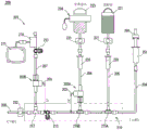
The fluid circuit system 200 of the present embodiment shown in fig. 1 is used for, for example, cardiac catheterization. The system 200 includes a fluid circuit set 201 (described in detail below) and a contrast chamber 221, a saline chamber 223, a transducer 270, and a syringe 251 connected to the circuit set 201. The fluid circuit system 200 further includes an injection head 260 (only a part of which is shown) for holding the syringe 251 and sucking and extruding the medical fluid.
Specifically, the fluid circuit set 201 of fig. 1 includes a syringe line 204 connected to a syringe 251, a contrast agent line 205 connected to a contrast agent chamber 221, a saline line 206 connected to a saline chamber 223, a transducer line 207 connected to a transducer 270, a patient line 208 connected to a patient via a catheter (not shown), and a base line portion 210 connected to the above-described lines.
The material, length and diameter of the pipes constituting the respective lines 204 to 208 may be appropriately selected in consideration of the pressure applied to the pipes. In the cardiac catheterization procedure, since the medical solution is injected at a high pressure, the portion to which the high pressure is applied is preferably formed of a high-pressure-resistant tube. Similarly, the double check valves 215A and 215B and the relief valves 202A and 202B, which will be described later, are also preferably high pressure-resistant valves.
As shown in FIG. 1, the "base line portion 210" refers to a portion connected to each of the lines 204 to 208, and is constituted by a pipe, a valve, a connector, and the like. In this example, an injector line 204 is connected to the upstream side of the base line portion 210, and a patient line 208 is connected to the downstream side. A contrast medium line 205, a saline line 206, and a transducer line 207 are connected to an intermediate portion of the base line portion 210 in this order from the upstream side. The pipelines 205 to 207 are connected to the base pipeline portion 210 in a T-shape.
In the present embodiment, the contrast medium line 205 and the saline line 206 are connected to the base line unit 210 by the duplex check valves 215A and 215B, respectively. As an example, the two double check valves 215A and 215B (described in detail later) may use the same double check valve or may use double check valves having different functions. In fig. 1, as an example, the same two-way check valve is used.
The double check valves 215A and 215B are valves having the following functions (see also fig. 2A):
(i) when the liquid is sucked toward the upstream side of the base line portion 210 (i.e., the syringe 251 side), the liquid is allowed to flow in a direction toward the upstream side of the base line portion 210.
(ii) On the other hand, when the double check valve 215A presses the liquid from the upstream side to the downstream side of the base line portion 210, the liquid flows to the downstream side through the valve 215A. Similarly, in the double check valve 215B, when the liquid is pressed toward the downstream side, or when the liquid is pressed from the saline line 206 side toward the valve 215B side, the liquid is allowed to flow in the direction toward the downstream side, or in the direction from the saline line 206 side toward the valve 215B side.
Further, as shown in fig. 2A, the two- way check valves 215A, 215B restrict the flow of the liquid from the downstream side to the upstream side and the flow of the liquid toward the lines 205, 206.
In fig. 1, the other valve 215A is disposed upstream of the double check valve 215B, and the upstream side flow of the liquid is restricted by the valve 215A, so that the saline is not sucked toward the upstream side in the circuit.
As shown in fig. 1, the converter line 207 is connected to the base line portion 210 with a connector 217 having no valve function as an example. A three-way cock 213 is provided between the connector 217 and the double check valve 215B. However, the position of the three-way cock 213 is not necessarily limited to this. As shown in fig. 2C, a stopcock valve 213 may be disposed downstream of an air sensor 232 (described in detail later) on the patient line 208.
As an example, the three-way cock 213 may be a three-way cock that closes one of the 3 lines connected thereto along the direction of the rod of the three-way cock 213 (for example, in the state of fig. 1, movement of liquid to a line extending downward, not shown) is prevented). Such a three-way stopcock is used in a case where an operator discharges a liquid in a line to the outside as needed.
Next, the facilities connected to the respective pipelines 204 to 208 will be described. Since conventionally known devices can be used as the devices, detailed description thereof will be omitted.
The syringe 251 connected to the syringe line 204 may be a syringe having a capacity of, for example, about several tens ml to 200ml, and the syringe 251 is preferably a syringe capable of performing high-pressure injection. A protective cap for covering the syringe 251 may also be used as needed. The syringe 251 has a cylindrical barrel member and a piston member (plunger rod) slidably inserted into the barrel member. Further, the piston member may be a so-called rodless type piston member.
The injector (injection head) 260 to which the syringe 251 is detachably attached is not limited, but is preferably of a type capable of performing, for example, high-pressure injection. The injector has a motor as a driving source and a pressing member that moves in the front-rear direction. The pushing member is pulled to pull the piston member of the syringe to fill the syringe with the chemical liquid, while the pushing member is pushed to push out the liquid in the syringe to the outside.
As an example, the contrast chamber 221 connected to the contrast line 205 may be a bottle-shaped container filled with contrast. The contrast chamber 221 may be used as a hanger, not shown, to which the contrast line 205 is connected at a lower portion of the contrast chamber 221. The connection can also be made via a needle valve.
As shown in fig. 1, an air sensor 231 (e.g., an infrared sensor) for detecting whether air is mixed in the liquid in the contrast agent line 205 is disposed below the contrast agent chamber 221. By detecting the air in the line by the air sensor 231, it is possible to detect that the chemical liquid in the chamber is not present. A drip chamber 233 is disposed below the air sensor 231 and above the contrast medium line 205, and when the contrast medium from the contrast medium chamber 221 drips into the chamber 233, the contrast medium flows from the chamber 233 into the contrast medium line 205.
The saline chamber 223 connected to the saline line 206 may be a bag-shaped container filled with a contrast medium, for example, and in this example, the saline chamber 223 further includes a pressurizing member 224 for pressurizing the bag (the saline chamber having such a structure is also referred to as a "pressurizing bag"). The pressurizing bag may be a commercially available pressurizing bag. The pressurizing member 224 is not limited, but the pressurizing member 224 may be a pressurizing member that compresses the bag using a fluid such as air as a driving source, or may be a pressurizing member that compresses the bag using a motor or the like as a driving source. The air sensor 231 and the drip chamber 233, which are the same as the air sensor 231 and the drip chamber 233 of the contrast medium line 205, are also disposed in the saline line 206. The mechanism for pressurizing the physiological saline is not limited to the above-described one, and other configurations will be described later.
The saline line 206 is provided with a release valve 202A for switching the opening and closing of the line 206. A specific configuration example of the release valve 202A will be described later with reference to fig. 11 to 19. The release valve 202A has a movable member 203 that moves by receiving an external force, and opens and closes the physiological saline line 206 by switching the open/closed state by moving the movable member 203. In the present embodiment, as an example, the movable member 203 is pressed to open the valve 202A, thereby causing the physiological saline from the pressurizing bag to flow toward the base line portion 210.
Next, the equipment and the like connected to the inverter line 207 will be described. As an example, the transducer 270 connected to the line 207 can monitor the patient's pulse by detecting blood pressure. As an example, the waveform of the pulse can be displayed on a display 271 connected to the transducer 270.
A release valve 202B, which is identical to the release valve 202A of the saline line 206, is also provided on the changer line 207. However, relief valve 202B is oriented opposite relief valve 202A. In the release valve 202B, the movable member 203 is pressed to bring the chemical liquid into a state of flowing toward the inverter 270.
In the example of fig. 1, a three-way cock 213 is disposed between the relief valve 202B of the converter line 207 and the converter 270. In addition, the movable member 203 of the one relief valve 202A and the movable member 203 of the other relief valve 202B are disposed to face each other. In order to correspond to the configuration of the switch 300 described later, the distances (L1, L2) from the base line portion 210 to the movable members 203, 203 of the respective valves are arranged to be different from each other.
The distal end portion of the patient line 208 is connected to a thin tube called a catheter (not shown) which is inserted into a blood vessel of a patient. In a cardiac catheter examination, a catheter tip is moved to, for example, a coronary artery, and a contrast medium or the like is injected into an blood vessel from the catheter tip.
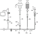
Next, a switcher 300 for holding a part of the liquid circuit set 201 of fig. 1 and appropriately switching the flow therein is explained with reference to fig. 2B. As an example, the switch 300 has a box-shaped housing 310. The switch 300 has a 1 st holding portion 306 for holding a portion of the saline line 206 and a 2 nd holding portion 307 for holding a portion of the changer line 207. The holding portions 306 and 307 are formed in a concave shape, and release valves 202A and 202B for the respective lines can be provided therein.
The housing 310 of the switcher 300 is provided with drive units 301 and 301 for electromechanically pressing the movable members 203 and 203 of the valves 202A and 202B using, for example, a motor as a drive source. The driving units 301 and 301 may be configured to operate in response to a control signal from an external controller 350. The controller 350 is not particularly limited in function, and may control the injector 260.
The switch 300 also has a 3 rd holding portion 308 for holding a portion of the patient line 208 and an air sensor 332 for detecting the presence or absence of air bubbles within the patient line 208. As an example, the air sensor 332 may be an ultrasonic type air sensor. The ultrasonic sensor 332 can favorably detect bubbles even when the bubbles are mixed in the liquid under high pressure conditions, as compared with an infrared air sensor or the like, and is advantageous in this respect.
Next, a method of using the liquid circuit set 200 of the present embodiment configured as described above will be described.
Fig. 3 shows an initial state in which the movable members 203, 203 of the relief valves 202A, 202B are not pressed and the liquid does not flow in both directions. When the operator presses a predetermined button (purge air button) of the injector 206 in the state of fig. 3, the piston driving mechanism operates to pull the piston member of the syringe 251. Thereby, negative pressure is generated in the syringe 251 and the syringe line 204, and the contrast medium in the chamber 221 is introduced into the syringe lines 205, 204 and the syringe 251 via the contrast medium line 205 and the double check valve 215A.
Next, as shown in fig. 4, the syringe 251 is pressed this time to push out the contrast medium from the syringe 251. Fluid is delivered to the base line portion 210 side through the syringe line 204 and fills the base line portion 210 through the two- way check valves 215A, 215B. This contrast medium expression continues until the contrast medium is expressed at least to the extent of crossing the double check valve 215B, as shown in fig. 4.
Next, as shown in fig. 5, the movable member 203 of the relief valve 202A and the movable member 203 of the relief valve 202B are pressed to open the two valves 202A and 202B. The opening is automatically performed by pressing the movable members by the driving portions 301 and 301 of the switcher 300. At this time, the pressurizing member 224 of the saline chamber 223 is driven, and a predetermined pressure (for example, about 300 mmHg) is applied to the saline. Thus, by opening valve 202A, saline will flow from the chamber 223 side toward the base line portion 210 and through the relief valve 202A and the two-way check valve 215B to the patient line 208 side. The contrast further passes through three-way stopcock valve 213 and branches at connector 217, with a portion flowing into patient line 208 and another portion flowing into changer line 207. Here, since the release valve 202B is opened, the saline flows toward the changer 270 across the release valve 202B. By filling each line with physiological saline in this manner, air bubbles in the line can be discharged to the outside.
Next, as shown in fig. 6, the movable member 203 of the release valve 202A in the saline line 206 is released from being pressed, and the saline flows downstream without passing over the release valve 202A. Further, in order not to allow the contrast medium to flow into the inverter 270 in the next contrast medium injection step, the movable member 203 of the release valve 202B of the inverter line 207 is released from being pressed, and the contrast medium or the like does not flow into the inverter side beyond the release valve 202B.
Next, the piston driving mechanism of the injector 206 is operated to press the piston member of the syringe 251, thereby pushing out the contrast medium in the syringe 251 toward the patient as shown in fig. 7. Specifically, the contrast agent is delivered to a predetermined imaging region (for example, coronary artery of the heart) in the patient body through the contrast agent line 204, the base line portion 210, the patient line 208, and a catheter (not shown).
After the contrast medium is injected and the residual pressure in the circuit is sufficiently reduced, the movable member 203 of the release valve 202A of the saline line 206 is pressed to open the valve again as shown in fig. 8. At this time, since a predetermined pressure (for example, about 300 mmHg) is applied to the saline by the pressurizing member 224 of the pressurizing bag, as in the above-described step, the saline is sent to the proximal line portion 210 and the patient line 208 to flush the contrast medium, as shown in fig. 8.
Next, as shown in fig. 9, if necessary, the release valve 202B of the transducer line 207 is opened, so that the saline flows into a region on the transducer side of the release valve 202B, and the saline is flushed in this region as well.
Thereafter, as shown in fig. 10, the movable member 203 of the check valve 202A in the saline line 206 is released from being pressed, and the saline flows into the proximal line portion 210 without going over the valve 202A. This releases the pressurized state of the physiological saline at the downstream side of the proximal line portion 210. As a result, the state shown in fig. 10 is obtained: a blood path is established via patient line 208 and transducer line 207, enabling blood pressure to be detected using transducer 270.
As described above, the liquid circuit set 201 of the present embodiment includes the contrast medium line 205, the saline line 206, the syringe line 204, the patient line 208, and the base line 210, and the double check valves 215A and 215B for restricting the flow of the liquid in a predetermined direction are provided at the connection portion between the contrast medium line 205 and the base line 210 and the connection portion between the saline line 206 and the base line 206. Therefore, the operator can perform operations such as aspiration of the contrast medium into the syringe 251 (fig. 3) and subsequent discharge of the contrast medium (fig. 4) without performing an operation of manually switching the three-way cock valve.
In the liquid circuit set 201 according to the present embodiment, a release valve 202A is provided in the saline line 206. In particular, since the release valve 202A is a release valve whose opening and closing are switched by pressing the movable member 203, the switching operation is easier than that of a type of release valve whose opening and closing are switched by a torsion bar, such as a three-way plug valve. Specifically, there is an advantage that switching can be easily performed automatically by a switch using an actuator such as a motor. Further, such movement of the movable member 203 can be performed in a shorter time than in the case of a torsion bar. In the case of the configuration in which the flow path is closed by the function of the relief valves 202A and 202B as in the present embodiment, the flow path can be closed more reliably than the configuration in which the flow path is closed by, for example, a flattened tube.
Further, in the configuration of the present embodiment, since the release valve 202B can be used to favorably close the transducer line 207, even when high-pressure injection such as a cardiac catheter test is performed, it is possible to prevent high-pressure liquid from flowing into the transducer 270, and further prevent the transducer 270 from being damaged or injured.
As an example, the fluid circuit set 201 of the present embodiment may be disposable with the contrast medium line 205, the saline line 206, the syringe line 204, the transducer line 207, the patient line 208, and the base line 210 as a single set. That is, the liquid circuit set 200 may be used a plurality of times, but for the purpose of preventing infectious diseases or the like, the liquid circuit set 201 may be replaced with a new one after being used for one patient. In this case, the drip chambers 233 and 233 (or only one of them may be included) including the saline line 206 and the contrast medium line 205 may be included as a disposable article.
In addition, the liquid circuit system of the present embodiment is a system using the liquid circuit kit 200 described above, and includes: an injector for carrying the syringe 251 to perform suction and injection (discharge) of liquid; and a switch 300 for automatically switching the opening and closing of a predetermined line of the liquid circuit set 200. With such a system, the operator can appropriately perform a series of injection operations of the contrast medium and the saline without switching the three-way stopcock, and can automatically perform all the steps as necessary.
The present invention is not limited to the above-described embodiments. For example, a tube pump (Japanese patent No. チューブポンプ) that continuously squeezes a flat tube to flow the saline in a predetermined direction in the tube may be used instead of the pressurizing bag as a structure for squeezing out the saline. Alternatively, a device in which the pumping and the extrusion of the physiological saline are repeated by reciprocating a piston member of a small syringe may be used, and the device may be a device using a cam mechanism and an urging member (e.g., a spring).
One specific example of a relief valve
Specifically, the relief valves 202A and 202B that can be used in the liquid circuit system 200 of fig. 1 may be the relief valves described below. In the following, a configuration example of the relief valve will be described with reference to fig. 11 to 19, but the present invention is not limited to the following steps. In addition, in the following, a valve corresponding to the release valves 220A and 220B will be described as a "check valve 1". The movable member 223 corresponds to the "movable pin 60".
The check valves shown in fig. 11 to 19 are used to switch between a state of a check valve that allows the chemical solution to move only in one direction and an open state that allows the chemical solution to move in two directions, but may be used as the release valve shown in fig. 1 to switch between a closed state that completely blocks the movement of the liquid and an open state that allows the liquid to move in two directions (the direction of the liquid flow depends on the pressure difference of the liquid).
The check valve 1 of the present embodiment shown in fig. 11 is mainly used in a medical fluid circuit. In particular, the check valve 1 has high pressure resistance and can be applied to, for example, cardiac catheterization. As shown in fig. 11 and 12, the check valve 1 includes: a housing 50 constituting the valve chamber 10; a disc-shaped valve body 25 disposed in the valve chamber 10; a movable pin 60 movably held on a part of the housing 50; and a cover 70 attached to the housing 50 so as to cover the movable pin 60.
The check valve 1 is connected to a supply pipe P1 and a discharge pipe P2. Basically, the check valve 1 allows the chemical liquid to flow only from the supply pipe P1 toward the discharge pipe P2, and allows the chemical liquid to flow in both directions only while the movable pin 60 is pressed. The direction in which the chemical flows depends on the pressure of the chemical in the pipes P1 and P2, and therefore the chemical can flow in a direction other than the above-described flow direction under a predetermined pressure condition. For example, under the condition that the hydraulic pressure on the P2 side is higher than the hydraulic pressure on the P1 side, the chemical liquid does not flow in the state where the movable pin 60 is not pressed, and the chemical liquid flows from the P2 side toward the P1 side only while the movable pin 60 is pressed.
As an example, the housing 50, the movable pin 60, the cover 70, and the support member 21 described later may be resin molded products, but the present invention is not limited thereto.
As shown in fig. 11 and 12, the housing 50 includes a housing main body 40 connected to the supply pipe P1 and a substantially cylindrical closing (closing) member 30 connected to the discharge pipe P2. When the closure member 30 is mounted to the housing main body 40, the valve chamber 10 is formed between the two members. An inlet 11 (fig. 12) for supplying the chemical liquid into the valve chamber is formed on the upstream side of the valve chamber 10, and an outlet 13 for sending the chemical liquid to the outside is formed on the downstream side of the valve chamber 10.
The valve chamber 10 has a substantially horizontal cylindrical shape, and the downstream side of the valve chamber 10 is tapered such that the cross-sectional area gradually decreases toward the outlet portion 13. A valve body 25 (described later in detail) for opening and closing the inlet portion 11 and a support member 21 (described later in detail) for pressing the valve body 25 are disposed in the valve chamber 10.
The shape of the housing main body 40 is explained in detail with reference to fig. 15. As shown in fig. 15, the housing main body 40 has: a cylindrical (one example) body portion 41 that constitutes the valve chamber 10; and a pipe holding portion 48 connected to the supply pipe P1, the pipe holding portion 48 being a cylindrical portion that is narrower than the body portion 41 provided on the upstream side thereof. The material of the housing main body 40 is not limited, and may be a material having a see-through property such that the inside of the valve can be seen, or a material having a non-see-through property.
The end of the supply pipe P1 is inserted into the inside of the pipe holding portion 48. The supply pipe P1 is connected to the inside of the pipe holding portion 48 with sufficient strength by a conventionally known method so that the pipe does not fall off even when the hydraulic pressure rises. In order to connect the supply pipe P1 with good workability, 1 or more ribs are formed on the pipe holding portion 48. In this example, 1 radially projecting rib 49f, 49f is formed on each of the upper and lower portions of the cylindrical portion 49.
As shown in fig. 15 and 16, the main body 41 has a cylindrical shape extending in the lateral direction, and includes a valve element 25 (see fig. 11) and a support member 21 (details of the above-described members will be described later) for pressing the valve element 25. As shown in fig. 16, an inlet 11 for supplying the chemical liquid is formed in a part of the wall surface 41h in the main body.
In this example, the inlet 11 is provided with a recess 11a (see fig. 14 and 16) formed so as to partially recess the wall surface 41h, and the recess 11a communicates with the flow path 11 c. As shown in fig. 14, an inclined surface 11b is formed at the boundary between the recess 11a and the flow path 11 c. As shown in fig. 16, the recess 11a has a circular outline, and 3 ribs 43Ra are formed in the recess 11a as an example. The ribs 43Ra are formed radially at equal intervals from each other. The rib 43Ra functions to support the front surface of the valve body 25 (described in detail later).
As shown in fig. 16, a plurality of support ribs 43Rb for supporting the outer peripheral portion of the valve body 25 are formed around the inlet portion 11. As an example, 6 support ribs 43Rb are arranged radially at equal intervals from each other.
As shown in fig. 11, the valve body 25 is, for example, a disk-shaped and flexible valve body (hereinafter, a valve body having no flexibility will be described again). The thickness of the valve core may be uniform. The valve body may be made of, for example, silicone rubber, and the hardness of the valve body is, for example, in the range of 5 ° to 90 °, preferably in the range of 40 ° to 80 °, and more preferably in the range of 60 ° to 80 °. The valve body 25 has a diameter enough to close the inlet portion 11.
As shown in fig. 18, the supporting member 21 for pressing the valve body 25 includes an annular frame 27, a pressing portion 23 having a substantially tapered shape (conical shape) disposed at a central portion of the frame 27, and 4 (one example) supporting arms 26 for connecting the pressing portion 23 and the frame 27 and supporting the pressing portion 23. The pressing portion 23 protrudes toward the valve body 25, and the pressing portion 23 presses the vicinity of the center portion of the back surface of the valve body 25 via the tip end portion thereof.
With such a supporting method by the supporting member 21, the vicinity of the outer peripheral portion of the valve body 25 is not restrained, and therefore can be elastically deformed freely. Basically, the valve body 25 blocks the inlet portion 11 as shown in fig. 12, and prevents the chemical liquid from flowing from the valve chamber 10 toward the supply pipe P1. On the other hand, when the chemical liquid is supplied from the supply pipe P1, the outer peripheral portion of the valve body 25 is elastically deformed by the hydraulic pressure of the chemical liquid, and the chemical liquid is allowed to flow into the valve chamber 10.
The description returns to the support member 21 again. As shown in fig. 18, each part of the support member 21 is formed in a rounded or tapered shape so that the air bubbles can be satisfactorily discharged to the outside of the valve chamber even when the air bubbles are mixed in the valve chamber. Specifically, a gentle rounded shape is formed on the upstream side of each support arm 26 in the flow direction. The frame 27 also has a tapered shape such that the thickness of the frame becomes thinner as it goes toward the upstream side in the flow direction. With this configuration, there is an advantage that bubbles can easily flow to the downstream side, as compared with the case where the cross-sectional shapes of the support arms 26 and the frame 27 are simple rectangles.
Further, the operation of removing the air bubbles is not limited, and for example, the entire check valve 1 may be lifted so that the discharge pipe P2 side is positioned upward, and the user may slightly knock the valve with a hand or a predetermined tool to expel the air bubbles to the downstream side. When the material of the case 40 is transparent, whether or not air bubbles remain in the case can be visually confirmed with good visibility. Further, in the case where the downstream side of the valve chamber 10 is formed in a tapered shape in which the sectional area gradually decreases toward the outlet portion 13 as in the present embodiment, it is possible to favorably expel the air bubbles to the outside.
As a modification of the above configuration, each support arm 26 may be tapered such that the cross-sectional shape of each support arm 26 becomes thinner toward the upstream side in the flow direction, instead of being rounded. In addition, the frame 27 may be provided with a round shape.
Reference is again made to fig. 12. The support member 21 is configured such that the outer peripheral portion thereof is sandwiched between the case main body 40 and the closing member 30 to be supported. With such a structure, it is not necessary to provide a dedicated part or structure for fixing the support member 21. In order to prevent the support member 21 from rotating in the valve chamber 10, as shown in fig. 15 and 18, a projection 27a may be formed on the outer peripheral portion of the frame 27, and the projection 27a may be engaged with the longitudinal groove 43g in the housing main body.
In the present embodiment, the movable pin 60 also has a predetermined tip shape so as not to retain air bubbles in the valve chamber 10, which will be described later.
Next, the movable pin 60 and the structural portion where the movable pin 60 is disposed will be described. As shown in fig. 12, the housing space 15 in which the movable pin 60 is disposed is formed by an outer tube 45 (described later in detail) of the housing body 40 and a cover 70 attached to the outer tube 45.
As shown in fig. 12 and 19, the cover 70 has a substantially bottomed cylindrical shape as a whole, and in this example, has a flat upper surface portion 71 and a cylindrical peripheral wall portion 73 extending downward from a peripheral portion of the upper surface portion 71. The upper surface 71 is provided with 1 opening, and a part of the movable pin 60 protrudes to the outside through the opening. As shown in fig. 19, a convex portion 76 (for example, a rectangular cross-sectional shape) is formed on the inner surface of the peripheral wall portion 73. In this example, 1 projection 76 is provided on each side of the peripheral wall 73.
In the present embodiment, the cover 70 is attached to the housing main body 40 with sufficient strength so that the cover 70 and the movable pin 60 do not fall off even when a high pressure is applied to the chemical solution during use. As a method for fixing the cover 70, for example, an adhesive, welding, or the like can be used, but a mechanical fixing method is preferable. As a mechanical fixing method, for example, a method of fitting a convex portion of one member into a concave portion of the other member, screwing screw portions to each other, or fixing both members by an additional fixture such as a screw or a fixing pin may be used.
In the present embodiment, as an example, the convex portion 76 (see fig. 19) on the inner side of the cover 70 is configured to engage with an L-shaped groove 45g (see fig. 14) formed on the outer periphery of the outer cylinder portion 45 of the housing. With such a fixing method, the cover 70 can be fixed with sufficient strength and with good positional accuracy. Further, if necessary, after the cap 70 is attached to the outer tube portion 45, it may be further fixed by an adhesive or the like.
Next, the movable pin 60 will be described. As shown in fig. 17, the movable pin 60 has, as an example, a shaft portion 61 having a circular cross-sectional shape and a flange portion 67 formed in a part of the shaft portion 61. An action portion 63 that can contact the valve body 25 is formed on the distal end side (lower end side) of the shaft portion 61.
As shown in fig. 14, the operation portion 63 is formed in a wedge shape so that the outer peripheral portion of the valve body 25 can be lifted from the wall surface 41 h. Specifically, the action portion 63 includes a protruding portion 63a that enters between the valve body 25 and the wall surface 41h, and a flat portion 63b that is formed on the downstream side of the protruding portion 63 a. Preferably, the flat portion 63 is configured such that, in a state where the movable pin 63 is positioned upward as shown by a broken line in fig. 14, the flat portion 63 is positioned on the same surface as the upper surface of the valve chamber 10 or protrudes from the upper surface of the valve chamber 10. Even if the flat surface 63 is located at a position recessed from the upper surface of the valve chamber, there is a possibility that air bubbles will accumulate in this portion, but by adopting the above configuration, the air bubbles can be favorably made to flow downstream.
Referring again to fig. 17, the shaft portion 61 is formed with an annular groove 61c into which an O-ring R1 (described in detail later) is fitted. The flange portion 67 is formed above the annular groove 61c, and 4 circular guide holes 67a are formed in the flange portion 67. The upper end of the shaft portion 61 is a portion to be pressed by a user or a predetermined mechanism, and the corner portion of the outer periphery of the upper end is rounded.
As shown in fig. 5, the movable pin 60 is disposed in the outer tube 45 of the housing body 41. An inner cylinder 46 is formed inside the outer cylinder 45, and the inner cylinder 46 is formed of 4 wall pieces 46a having an arc-shaped cross section. When the movable pin 60 is disposed in the outer tube portion 45, the wall pieces 46a are inserted into the guide holes 67a of the movable pin. Each of the wall pieces 46a functions as a member for guiding the movement of the movable pin 60 in the vertical direction, and functions to prevent the movable pin 60 from rotating around the center axis.
The movable pin 60 configured as described above is configured to be movable vertically as shown in fig. 12 and 13. First, the state of fig. 12 in which the movable pin 60 is located at the 1 st position (upper position) will be described.
In this state, the movable pin 60 is lifted upward by the biasing force of the coil spring 68 disposed below the flange portion 67 of the movable pin 60, and the upper surface of the flange portion 67 is pressed against the inner surface of the lid 70. The flange portion 67 is formed to have a diameter larger than that of the opening portion of the lid 70, so that the movable pin 60 does not come off the lid. In the present embodiment, since both the upper surface of the flange portion 67 and the inner surface of the lid 70 are flat surfaces and both members are in surface contact, the lid 70 can uniformly receive a force from the flange portion 67.
When the movable pin 60 is located at the 1 st position, the operating portion 63 of the movable pin 60 is separated from the valve body 25, and the valve body 25 closes the inlet portion 11. In this state, the check valve 1 functions as a check valve that allows only the chemical liquid to flow from the supply pipe P1 side to the discharge pipe P2 side. Further, as described above, the direction in which the chemical liquid flows depends on the pressure of the chemical liquid in the pipes P1, P2, and, for example, in the case where the valve 1 is used in a liquid circuit in which the liquid pressure on the P2 side is higher than the liquid pressure on the P1 side, the chemical liquid does not flow in a state where the movable pin 60 is not pressed, and the chemical liquid flows from the P2 side toward the P1 side only while the movable pin 60 is pressed. The check valve 1 of the present embodiment is not a check valve that restricts the flow of the chemical liquid to a specific direction.
On the other hand, in fig. 13, the movable pin 60 is pushed downward and moved to the 2 nd position (lower position). When the movable pin 60 is pressed against the biasing force of the coil spring 68 and the movable pin 60 moves to the position of fig. 13, the action portion 63 of the movable pin 60 enters between the valve body 25 and the wall surface 41h (fig. 14) and elastically deforms the outer peripheral portion of the valve body 25, thereby opening the inlet portion 11. As a result, the chemical liquid can be caused to flow in two directions (which direction the chemical liquid flows depends on the hydraulic pressures in P1 and P2). When the pressing of the movable pin 60 is stopped in the state of fig. 13, the following state is achieved: the movable pin 60 returns to the 1 st position again by the biasing force of the coil spring 68, the valve body 25 returns to its original shape to close the inlet portion 11, and the valve 1 functions as a check valve.
As described above, in the check valve 1 of the present embodiment, the valve can be appropriately switched in the communication state by pressing the movable pin 60. The method of pressing the movable pin 1 is not particularly limited, and for example, the user may press the movable pin 60 with a hand or using a predetermined tool, or may press the movable pin 60 with a predetermined mechanism.
By additionally describing the assembled state of the valve with reference to fig. 12 and 13, the O-ring R1 is fitted into the movable pin 60, whereby the sealing property between the movable pin 60 and the inner tube portion 46 can be ensured. In the case of such a configuration, the inner cylindrical portion 46 is urged radially outward by the force from the O-ring R1, but in the present embodiment, as shown in fig. 13, the tip end of each wall piece 46a constituting the inner cylindrical portion 46 is configured to be fitted into the locking groove 71g formed in the inner surface of the upper surface portion 71 of the lid 70. Therefore, the distal end side of the inner cylinder portion 46 can be prevented from expanding, and as a result, the sealing performance by the O-ring R1 can be maintained well even in use.
Specific materials of the components constituting the check valve 1 are not particularly limited, and the movable pin 60 may be, for example, polyacetal resin (POM) having good slidability. As an example, the component constituting the housing 50 may be polycarbonate resin (PC). Further, if necessary, a fine concave-convex shape may be formed on the outer peripheral surface of the valve body 25 (particularly, the surface facing the wall surface 41 h).
As described above, the check valve 1 according to the present embodiment can temporarily release the function as a check valve by moving the movable pin 60. The movable pin 60 is disposed in the housing space 15, and the movable pin 60 is configured so as not to come off the cover 70. Therefore, even if the pressure of the chemical liquid rises during use and a large force is applied to the movable pin 60 in such a direction as to press the pin out, the force can be received by the lid 70 via the flange portion 67, and therefore the movable pin 60 does not fall off. Therefore, the check valve 1 of the present embodiment can satisfactorily cope with high-pressure injection of the chemical solution.
In the present embodiment, the cover 70 is fixed to the housing 50 using mechanical fixing members (45g, 76). Therefore, the cover 70 can be fixed with sufficient strength and with good positional accuracy, as compared with a case where the cover 70 is fixed only with an adhesive, for example.
In the present embodiment, since the recess 11a as shown in fig. 16 is formed in the inlet portion 11 of the valve chamber 10, the inlet portion 11 can be reliably opened only by slightly deforming the valve body 25. That is, when such a recess 11a is not formed, the valve body 25 needs to be deformed to such an extent that the central flow path 11c is opened in order to open the inlet 11. In contrast, with the configuration of the present embodiment, as shown in fig. 16, at the time when the outer peripheral portion of the valve body 25 is deformed, the recess 11a is opened and the flow path 11c communicating with the recess 11a is also opened, so that the inlet portion 11 can be opened and closed by slight deformation of the valve body 25.
On the other hand, when the recess 11a is provided in this manner, the hydraulic pressure applied to the back surface of the valve body 25 becomes a problem when the valve is used. That is, although this problem differs depending on what kind of liquid circuit the valve 1 is used in, it is conceivable that: even when the hydraulic pressure in the valve chamber 10 becomes very high during use, the valve body 25 is pressed against the recess 11a by the hydraulic pressure. In this case, if the support rib 43Ra is not provided in the recess 11a, the valve body 25 may be stuck to the recess 11 a. In this state, even if the action portion 63 of the movable pin 60 is pressed into between the valve body 25 and the wall surface 41h, there is a possibility that the inlet portion 11 cannot be sufficiently opened. In contrast, when the support rib 43Ra is formed in the recess 11a as in the present embodiment, the valve body 25 can be prevented from sticking to the recess 11a, and the inlet 11 can be satisfactorily opened and closed by operating the movable pin 60. The support rib 43Ra is not necessarily limited to the shape shown in fig. 16, and may be formed as a projection having an arbitrary shape protruding from the bottom of the recess 11 a.
While one embodiment of the present invention has been described above with reference to the drawings, the present invention is not limited to the above description, and various modifications are possible.
For example, although the valve body 25 has flexibility and the outer peripheral portion of the valve body 25 can be elastically deformed, the valve body 25 may not have flexibility. For example, the valve body may be a plate-shaped member having no flexibility, and may be configured to be displaceable between (a) a position where the inlet portion 11 is closed and (b) a position where the inlet portion 11 is opened. When the movable pin 60 is pressed, the valve body is displaced to the position of (b), thereby opening the inlet portion 11. In this case, at least the pressing portion 23 of the support member 21 may have elasticity, and the displacement of the valve body may be allowed by the elastic contraction of the pressing portion.
The shape of the pressing portion of the support member is not limited to the conical shape, and may be, for example, a truncated cone shape.
When the cover 70 is fixed to the housing 50 with sufficient strength so as not to disengage the movable pin 60 when the check valve 1 is used, the shape of the cover 70 is not particularly limited, and may be a shape other than a bottomed cylinder.
The shape of the movable pin 60 is not limited as long as it is a member that moves by receiving an external force and operates the valve body 25, and may be a shape other than a pin shape. When the movable pin 60 has a pin shape as in the present embodiment, the cross-sectional shape is not limited to a circular shape, and may be a rectangular shape, a polygonal shape, or the like. Further, although the above-described embodiment illustrates the structure in which the flange portion 67 of the movable pin 60 abuts against the upper surface of the cover 70 as the structure for preventing the disengagement of the movable pin 60, the structure for preventing the disengagement is not limited to the flange, and may be a simple projection or the like provided on the outer periphery of the movable pin. In order to make it easy for the user to press the movable pin 60 with a hand, an additional cover (not shown) may be attached to the protruding portion of the movable pin 60.
In the above example, the housing 50 is composed of the housing main body and the closing member 30, but the number of parts and the shape thereof are not limited as long as the housing is a member forming the valve chamber 10.
The valve body 25 is not limited to a circular outline shape, and may have an outline shape such as an oval shape, a rectangular shape, or a polygonal shape. In addition, although the valve body 25 is assumed to have a constant thickness as described above, the thickness of the valve body 25 may be different depending on the location.
Other functions of the valve
The check valve according to another embodiment of the present invention may be as follows.
An open function check valve, wherein the open function check valve comprises: a housing forming a valve chamber having an inlet and an outlet for liquid; a valve body disposed in the valve chamber so as to close the inlet port, and configured to be elastically deformable or displaceable so as to open the inlet port; and a movable member movably held by the housing, the movable member being moved to abut against the valve body to elastically deform or displace the valve body, and when the movable member is pressed, the liquid chemical of an amount corresponding to a moving amount of the movable member is pushed out of the valve chamber through the outlet.
The valve is described with reference to fig. 13. The valve is configured to push out a small amount of chemical liquid corresponding to the amount of movement of the movable pin 60 from the valve chamber 10 when the movable pin 60 is pressed. On the other hand, when the pressing of the movable pin 60 is stopped, the movable pin 68 is returned to the original position by the coil spring 68, and the valve body 25 is temporarily deformed to allow the chemical solution to be replenished into the valve chamber 10 again. Thus, the function of pressing out a small amount of medical fluid by operating the movable pin 60 is effective particularly when contrast medium is injected during, for example, a cardiac catheterization. That is, in such an examination procedure, the catheter is inserted into the blood vessel of the patient, but when the one-way valve has the above-described function, a small amount of the contrast medium can be output from the distal end of the catheter, and as a result, for example, it is possible to satisfactorily confirm at which site in the patient the distal end of the catheter is currently located.
Pump device of PIT type
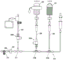
In the chemical liquid circuit system of the present invention, the pump device 226 shown in fig. 20 may be used instead of the pressurizing member 224 (fig. 1) for physiological saline. In fig. 20, only a part of the liquid medicine circuit system is shown. The same structure as that of fig. 1 can be used for the structure downstream of the three-way cock 213.
This pump device 226 is a pump device of the type disclosed in, for example, japanese patent No. 3626264. The pump device 226 includes a main body 227 for mounting a small syringe 226a and a piston driving mechanism (not shown) for advancing and retracting a piston member of the syringe 226 a.
In order to realize the transfer of the saline by the pump device 226, a part of the circuit in the configuration of fig. 20 is modified from the circuit of fig. 1. Specifically, connectors 215C and 215D are used instead of check valves 215A and 215B, and a check valve V-1 is disposed between the two connectors. Further, as indicated by the triangular marks in fig. 20, the check valve V-1 is disposed to permit the flow of the chemical liquid to the downstream side but not to permit the flow of the chemical liquid in the reverse direction. The flow restricting direction of the other check valve is determined based on the direction indicated by the triangle in fig. 20, similarly to the check valve V-1.
A connection connector 234, a drip chamber 233, an air sensor 231, and a check valve V-2 are disposed in this order from the side close to the chamber 221 on the line 205 connecting the connector 215C and the contrast chamber 221. The arrangement of the above-described constituent elements 234, 233, and 231 can be changed as appropriate.
The line 206 connecting the connector 215D and the saline chamber 223 is divided into two lines on the way, one line being the line 206 and the other line being the line 209 going to the pump device 226. As shown in FIG. 20, two check valves V-3 and V-4 are provided in the line 206.
There are also 1 one-way valves V-5 between the connector 215D and the three-way stopcock 213. Further, the check valve V-5 may be omitted. When the check valve V-5 is provided, the circuit downstream of the check valve may be a disposable article. Alternatively, the circuit downstream of the connector 215D may be a disposable article regardless of the presence or absence of the check valve V-5.
Further, a drug solution tube (not shown) may be connected to the three-way cock 213, and a drug solution may be injected into the patient through the drug solution tube.
In the chemical liquid circuit system of fig. 20 configured as described above, the following operations can be repeated by operating the pump device 226 to move the piston member of the small syringe 226a forward and backward: (i) sucking saline from chamber 223 into syringe 226a, and (ii) ejecting saline from small syringe 226 a. This enables the patient to be infused with physiological saline.
In the configuration of fig. 20, as an example, a load sensor 223S for measuring the weight of the saline chamber 223 is provided. A control device (not shown) determines whether or not the output value of the load sensor 223S is equal to or less than a predetermined set value (that is, whether or not the remaining amount of the physiological saline is equal to or less than a certain reference value) based on the output value or a value obtained by converting the output value into a load. When it is determined that the setting value is equal to or less than the predetermined setting value, a predetermined warning is given to the operator (for example, a lamp is turned on, a message is displayed, and a voice or a voice is output).
Of course, the load sensor 223S as described above can be used in the chemical liquid circuit system according to the embodiment of fig. 1.
In order to omit the air sensor 231 in the chemical liquid circuit system of fig. 20, for example, a connector having a floating valve body as disclosed in japanese patent application laid-open No. 9-117505 can be used in the drip chamber, and thus air can be prevented from being mixed into the patient line side. Further, it may be determined whether the drip chamber is empty or not based on the position of the valve element, and control such as stopping the injection may be performed when the drip chamber is empty.
The chemical liquid circuit system of fig. 20 is a system having the following liquid circuit set. A medical fluid circuit set for use in angiography, wherein the fluid circuit set comprises: a contrast line connected to the contrast chamber; a saline line connected with the saline chamber; an injector line connected with the injector; a patient line for delivering contrast media or saline toward a patient; and a base line part connected to the respective lines, and connected to the contrast medium line and the physiological saline line in a T-shape, respectively, and the liquid circuit set further includes: a. a 1 st valve member (V-1, V-2) configured to (i) allow a contrast medium to flow from a contrast medium line into the base line section when the liquid is sucked toward an upstream side of the base line section, and (ii) allow the liquid to flow in the direction through the valve member when the liquid is pressed from the upstream side toward a downstream side of the base line section; b. a 2 nd valve member (V-1) which permits the flow of the liquid in the direction and does not permit the flow in the reverse direction when the liquid is pressed from the upstream side toward the downstream side of the base line portion; and c, a 3 rd valve member (V-3, V-1) which permits the flow of the physiological saline to the patient line side and does not permit the flow of the physiological saline to the syringe line side when the physiological saline is supplied from the physiological saline chamber by the member for supplying the physiological saline.
About roller pump device
As a means for pressurizing the chemical solution chamber and delivering the chemical solution, a roller pump 470 as shown in fig. 21 can be used. As an example, the pump 470 includes a pair of pressing members 471 and 472 arranged to sandwich the chamber 223. By bringing one of the pressing members 471 and 472 closer to the other pressing member, the chamber 223 between the two pressing members 471 and 472 can be pressed, and thus the chemical liquid in the chamber 223 can be pushed out.
The specific structure can be appropriately designed or modified, and as an example, two members may be connected to each other at the hinge portion 474, and one member may be rotatable with respect to the other member. Rollers 476 may also be provided to bring one member closer to the other. The roller 476 may be configured to move downward as indicated by an arrow shown in the drawing while rotating around a rotation center 476a (a drive source may or may not be provided), thereby pressing the pressing member 471 toward the other member 472.
Pump device of piston type
A piston-type pump 480 as shown in fig. 22 can also be used. The pump 480 includes two syringes 481 and 486 connected in series, and the tip of the syringe 481 at the front is connected to the line 209 (see fig. 20). A short pad 482a is slidably disposed in the front syringe 481, and a projection 485 is formed on the back surface of the pad 482 a. The projection 485 functions to limit the movable range when the pad 482a moves rearward, but the projection 485 is not necessarily formed.
The distal end of the rear syringe 486 is formed to be elongated and is inserted into a through hole formed in the seal member 482b of the front syringe 481. Thus, the liquid or gas in the rear syringe 486 can be transferred to the front syringe 481 and sucked from the front syringe 481. The pump 480 is further provided with a driving means (not shown) for moving the piston member of the rear syringe 486 forward and backward.
In the medical fluid circuit system according to the present invention, as described above, the pumping and injection of the physiological saline can be performed by using the pump device 480 of the type shown in fig. 22.
Other constructions of relief valves
As the relief valves 202A and 202B in fig. 1, a relief valve having a structure as shown in fig. 23 may be used. Note that in fig. 23 (and fig. 24 described later), a part of the structure is schematically depicted.
The relief valve 401A in fig. 23 includes a hollow main body member 411 as a member constituting the housing 410, a pipe connecting member 412 connected to a lower portion of the main body member 411, and a cover member 413 for closing an upper end opening of the main body member 411. Further, a shaft member 425 is disposed in the main body member 411 so as to be movable upward and downward. The shaft member 425 is provided with two seal members 428 and 429, and a flange portion 425f is formed in a part of the shaft member 425.
The shaft member 425 is biased upward by a coil spring S1 (fig. 23), and in this state, the flange portion 425f is pressed against the seal member 429. In this state, the fluid does not flow from the lower end opening 412a of the connecting member 412 toward the side opening 411a of the main body member 411 (or in the opposite direction).
On the other hand, when the end portion of the shaft member 425 protruding upward from the central portion of the cover member 413 is pressed, the flange portion 425f moves downward, and therefore, a fluid flow path (detailed structure not shown) is opened, and thus, the fluid can flow from the lower end opening portion 412a of the connecting member 412 toward the lateral opening portion 411a of the body member 411 (or in the opposite direction). Further, the flow path for the fluid may be formed, for example, by a groove formed in the outer peripheral portion of the shaft member 425 along the longitudinal direction of the shaft member 425 to form a part of the flow path.
As described above, the release valve 401A shown in fig. 23 may be used in the chemical liquid circuit system of the present invention.
In addition, a relief valve 401B as shown in fig. 24 may be used. The relief valve 401B in fig. 24 includes a hollow main body member 411 as a member constituting the housing 410, and a cover member 413 for closing an upper end opening of the main body member 411. A shaft member 425 is disposed in the main body member 411 so as to be movable upward and downward. The shaft member 425 is provided with 1 sealing member 429 and an O-ring R1. A pressing member 416 having a flow path formed therein is attached to an upper end of the shaft member 425 protruding upward from the cover member 413. The pressing member 416 has a side opening 416a constituting a fluid inlet/outlet.
Similarly, in the relief valve 401B configured as described above, in a state where the shaft member 425 is not pressed, the flange portion 425f is pressed against the seal member 429 by the biasing force of the coil spring S1, and as a result, the fluid does not flow from the lower end opening portion 411a toward the side opening portion 416a of the pressing member 416 (or in the opposite direction thereto). On the other hand, when the cap member shaft member 425 is pressed, a fluid flow path (detailed structure not shown) is opened, and thus the fluid can flow.
Other constructions
Although an example of the present invention has been described above with reference to the drawings, various conventionally known structures, devices, and apparatuses can be applied to the circuit system of the present invention. For example, a structure called an octopus tube (Japanese: タコ tube) may be provided at an arbitrary position of the circuit in order to prevent air bubbles from being injected into the patient. As an example, in the configuration of fig. 1, an octopus tube may be provided between the connector 217 and the air sensor 232. The "octopus tube" is a protruding portion (may have any shape) such as a head portion of an octopus, which is formed to have a hollow interior, and traps bubbles flowing through the fluid circuit. Therefore, the octopus tube is preferably disposed so as to protrude vertically upward. In order to prevent the posture of the octopus tube from being changed, it is preferable to provide the octopus tube at a position where the orientation of the pipeline (tube) is stable in the circuit system.
Description of the reference numerals
1. A one-way valve; 200. a liquid circuit system; 201. liquid loop set; 202A, 202B, a release valve; 203. a movable member; 205. a contrast agent line; 206. a physiological saline line; 207. a converter line; 208. a patient line; 209. a pipeline; 210. a base line portion; 213. a three-way plug valve; 215A, 215B, a duplex one-way valve; 215C, 215D, connector; 223. a saline chamber; 223S, a sensor; 226. a pump device; 226a, a syringe; 227. a main body portion; 231. 232, an air sensor; 251. an injector; 260. an injector; 270. a converter; 300. a switch; 301. a drive section; 332. an air sensor; 401A, 401B, a release valve; 410. a housing; 411. a body member; 412. a pipe connection member; 413. a cover member; 428. 429, a sealing member; 470. a roller pump; 476. a roller; 480. a piston pump; 481. 486, an injector; v-1 to V-1, a one-way valve; s1, a spiral spring.
Claims (21)
1. A medical liquid medicine circuit for use in angiography, wherein,
the liquid medicine circuit includes:
a contrast line connected to the contrast chamber;
a saline line connected with the saline chamber;
a contrast agent injector line connected with the contrast agent injector;
a patient line for delivering contrast media or saline toward a patient;
a base line part connected to the contrast agent line and the physiological saline line;
an inverter line having one end connected to the proximal line portion at a position downstream of the position where the physiological saline line is connected, and having the other end connected to an inverter;
a 1 st check valve that is disposed on the contrast medium line, and allows a flow from the contrast medium chamber side to the proximal line portion side but does not allow an opposite flow;
a 2 nd check valve which is disposed between a portion of the base line portion to which the contrast agent line is connected and a portion of the base line portion to which the physiological saline line is connected, and which permits a flow from the contrast agent injector line side to the patient line side but does not permit an opposite flow;
a 3 rd check valve which is disposed on the saline line, allows a flow from the saline chamber side to the basal line portion side, and does not allow a reverse flow; and
and a 5 th check valve which is disposed at a position closer to the patient line than a position connected to the saline line and upstream of a position connected to the transducer line in the basal line section, and which permits a flow from the basal line section side to the patient line side but does not permit a reverse flow.
2. The medical fluid circuit of claim 1,
at least one of the contrast agent line and the physiological saline line is provided with an air sensor for detecting air entrainment.
3. The medical fluid circuit of claim 2, wherein,
the air sensor uses an infrared sensor.
4. The medical fluid circuit of claim 2, wherein,
the air sensor is an ultrasonic sensor.
5. The medical fluid circuit of claim 1,
at least one of the contrast medium line and the physiological saline line is provided with a drip chamber, and the medical solution is dripped into the drip chamber.
6. The medical fluid circuit of claim 1,
an air sensor for detecting air entrainment is provided in at least one of the contrast medium line and the physiological saline line,
a drip chamber is provided in at least one of the contrast medium line and the physiological saline line,
the air sensor is provided on either the upstream side or the downstream side of the drip chamber.
7. The medical fluid circuit of claim 1,
the medical fluid circuit further includes a saline syringe line branched from a midway point of the saline line, and the saline syringe line is connected to the saline syringe.
8. The medical fluid circuit as claimed in any one of claims 1 to 6,
the patient line is provided with an air sensor for detecting air entrainment.
9. The medical fluid circuit of claim 8,
the air sensor of the patient line utilizes an infrared sensor.
10. The medical fluid circuit of claim 8,
the air sensor of the patient line utilizes an ultrasonic sensor.
11. A medical fluid injection system, wherein,
the liquid medicine injection system includes:
the medical fluid circuit of claim 7;
a 1 st piston driving mechanism for holding the contrast medium injector and operating a piston member of the contrast medium injector,
and a 2 nd piston driving mechanism for holding the physiological saline injector and operating a piston member of the physiological saline injector.
12. The medical fluid injection system according to claim 11,
the medical fluid injection system also includes a saline chamber and a contrast chamber.
13. The medical liquid injection system according to claim 11 or 12,
the chemical solution injection system further includes a means for switching the opening and closing of a predetermined line of the chemical solution circuit.
14. The medical fluid injection system according to claim 13,
the means for switching between opening and closing is provided in at least one of the transducer line and the saline line.
15. A medical fluid circuit, comprising:
a contrast line connected to the contrast chamber;
a saline line connected with the saline chamber;
a base line part connected to the contrast agent line and the physiological saline line;
a patient line provided to extend from the base line portion and configured to convey a contrast medium or a saline solution toward a patient; and
a contrast agent injector line having one end side connected to the contrast agent line, the contrast agent injector line being configured such that when the contrast agent in the contrast agent chamber is sucked into the contrast agent injector and when the contrast agent in the contrast agent injector is transported toward the patient, the contrast agent flows inside the contrast agent injector line,
a contrast agent and a saline solution can be delivered toward a patient through the base line portion and the patient line, wherein,
the liquid medicine circuit includes:
a check valve disposed on the proximal line portion, the check valve being disposed on the patient line side of a junction between the contrast agent line and the proximal line portion and a junction between the physiological salt water line and the proximal line portion, the check valve allowing a flow from the proximal line portion side to the patient line side but not allowing a reverse flow;
and a transducer line having one end connected to a position downstream of the one-way valve in the proximal line portion, that is, a position on the patient line side, and having the other end connected to a transducer for monitoring a blood flow state of the patient.
16. The medical fluid circuit of claim 15, wherein,
the medical fluid circuit further includes an air sensor provided downstream of the check valve, that is, on the patient line side.
17. A system for injecting a liquid medicine into a patient,
the liquid medicine injection system includes:
the medical fluid circuit of claim 15 or 16, further comprising a saline syringe line branching from midway of the saline line at which the saline syringe is connected;
a 1 st piston driving mechanism for holding the contrast medium injector and operating a piston member of the contrast medium injector,
and a 2 nd piston driving mechanism for holding the physiological saline injector and operating a piston member of the physiological saline injector.
18. The medical fluid injection system according to claim 17,
the medical fluid injection system also includes a contrast chamber.
19. The medical fluid injection system according to claim 17,
the medical fluid infusion system also includes a saline chamber.
20. The medical fluid injection system according to claim 17,
the medical fluid injection system also includes a transducer.
21. The medical fluid injection system according to claim 17,
the liquid medicine injection system also comprises an injection head at least provided with the 1 st piston driving mechanism.
Applications Claiming Priority (3)
| Application Number | Priority Date | Filing Date | Title |
|---|---|---|---|
| JP2011156089 | 2011-07-14 | ||
| JP2011-156089 | 2011-07-14 | ||
| CN201280044808.9A CN103813818B (en) | 2011-07-14 | 2012-07-13 | The fluid loop system that therapeutic medical fluid loop is set with and uses this fluid loop to be set with |
Related Parent Applications (1)
| Application Number | Title | Priority Date | Filing Date |
|---|---|---|---|
| CN201280044808.9A Division CN103813818B (en) | 2011-07-14 | 2012-07-13 | The fluid loop system that therapeutic medical fluid loop is set with and uses this fluid loop to be set with |
Publications (2)
| Publication Number | Publication Date |
|---|---|
| CN106943642A CN106943642A (en) | 2017-07-14 |
| CN106943642B true CN106943642B (en) | 2020-11-27 |
Family
ID=47506204
Family Applications (2)
| Application Number | Title | Priority Date | Filing Date |
|---|---|---|---|
| CN201280044808.9A Expired - Fee Related CN103813818B (en) | 2011-07-14 | 2012-07-13 | The fluid loop system that therapeutic medical fluid loop is set with and uses this fluid loop to be set with |
| CN201610833688.0A Active CN106943642B (en) | 2011-07-14 | 2012-07-13 | Liquid circuit set for medical use and liquid circuit system using the same |
Family Applications Before (1)
| Application Number | Title | Priority Date | Filing Date |
|---|---|---|---|
| CN201280044808.9A Expired - Fee Related CN103813818B (en) | 2011-07-14 | 2012-07-13 | The fluid loop system that therapeutic medical fluid loop is set with and uses this fluid loop to be set with |
Country Status (3)
| Country | Link |
|---|---|
| JP (4) | JP6071880B2 (en) |
| CN (2) | CN103813818B (en) |
| WO (1) | WO2013008929A1 (en) |
Families Citing this family (13)
| Publication number | Priority date | Publication date | Assignee | Title |
|---|---|---|---|---|
| BR112018014935B1 (en) * | 2016-02-09 | 2023-03-21 | Bracco Injeneering Sa | METHOD OF OPERATION OF AN INJECTION SYSTEM |
| CN106975120B (en) * | 2017-04-19 | 2018-09-07 | 刘桂芝 | A kind of infusion bottle automatic decanting device |
| WO2019046260A1 (en) * | 2017-08-31 | 2019-03-07 | Bayer Healthcare Llc | Method for dynamic pressure control in a fluid injector system |
| CN107929870B (en) * | 2017-12-15 | 2023-09-19 | 广东省人民医院(广东省医学科学院) | Single-cylinder double-tube radiography device |
| JP7128985B2 (en) * | 2018-04-17 | 2022-09-01 | 株式会社ジェイ・エム・エス | infusion set |
| US20210369950A1 (en) * | 2018-06-29 | 2021-12-02 | Circulus Inc. | Chemical liquid injecting apparatus |
| CN108939219B (en) * | 2018-07-06 | 2021-03-19 | 深圳市国赛生物技术有限公司 | Bubble removing method and bubble removing system in plunger pump cavity and storage medium |
| WO2020047767A1 (en) * | 2018-09-05 | 2020-03-12 | 深圳市迈威生物科技有限公司 | Disposable assembly and fluid delivery system |
| CN109350114B (en) * | 2018-11-28 | 2023-07-04 | 广东省人民医院(广东省医学科学院) | Multifunctional heart color ultrasound imaging examination device |
| CN110639082A (en) * | 2019-09-27 | 2020-01-03 | 南通大学 | Infusion device with automatic bottle changing and infusion functions |
| KR102367650B1 (en) * | 2019-11-01 | 2022-02-28 | 김용현 | Medicinal liquid supply regulating apparatus and medicinal liquid injection apparatus including the same |
| JP7144464B2 (en) * | 2020-01-20 | 2022-09-29 | ディーブイエックス株式会社 | Contrast injection device and injection line kit |
| BE1028541B1 (en) | 2021-12-20 | 2023-07-12 | P&R Medical Bv | FLUID DELIVERY SYSTEM |
Family Cites Families (16)
| Publication number | Priority date | Publication date | Assignee | Title |
|---|---|---|---|---|
| JPH0325369A (en) * | 1989-06-22 | 1991-02-04 | Toshiba Corp | Check valve for automatic chemical analyzer |
| US6315762B1 (en) * | 1996-11-14 | 2001-11-13 | Angiodynamics, Inc. | Contrast medium delivery system and associated method |
| JP4021621B2 (en) * | 1998-06-29 | 2007-12-12 | スーガン株式会社 | Channel switching device |
| JP4293689B2 (en) * | 1999-10-05 | 2009-07-08 | 株式会社根本杏林堂 | Contrast medium injection device |
| US6626862B1 (en) * | 2000-04-04 | 2003-09-30 | Acist Medical Systems, Inc. | Fluid management and component detection system |
| US7172572B2 (en) * | 2001-10-04 | 2007-02-06 | Boston Scientific Scimed, Inc. | Manifold system for a medical device |
| JP3809114B2 (en) * | 2001-11-05 | 2006-08-16 | スーガン株式会社 | Channel switching device and contrast medium injection tube used in the device |
| JP2004065737A (en) * | 2002-08-08 | 2004-03-04 | Nemoto Kyorindo:Kk | Liquid chemical injecting apparatus |
| US6918907B2 (en) * | 2003-03-13 | 2005-07-19 | Boston Scientific Scimed, Inc. | Surface electrode multiple mode operation |
| JP4338446B2 (en) * | 2003-06-05 | 2009-10-07 | 株式会社根本杏林堂 | Chemical injection device |
| JP4654129B2 (en) * | 2003-07-18 | 2011-03-16 | 株式会社根本杏林堂 | A chemical injection device that displays an image of the input injection conditions |
| US7097690B2 (en) * | 2003-10-10 | 2006-08-29 | Scimed Life Systems, Inc. | Apparatus and method for removing gasses from a liquid |
| JP2008540117A (en) * | 2005-05-16 | 2008-11-20 | マリンクロッド・インコーポレイテッド | Multi-cylinder syringe with integrated manifold |
| JP2007222656A (en) * | 2007-04-10 | 2007-09-06 | Medrad Inc | Fluid delivery system, pressure isolation mechanism, injector control mechanism, and method of using them |
| WO2011055790A1 (en) * | 2009-11-09 | 2011-05-12 | 株式会社根本杏林堂 | One-way valve with opening function, tube unit provided with the one-way valve, and drug solution injection system |
| WO2011066865A1 (en) * | 2009-12-03 | 2011-06-09 | Jean-Pierre Peters | Fluid interconnection set with particle filter |
-
2012
- 2012-07-13 CN CN201280044808.9A patent/CN103813818B/en not_active Expired - Fee Related
- 2012-07-13 JP JP2013524009A patent/JP6071880B2/en active Active
- 2012-07-13 CN CN201610833688.0A patent/CN106943642B/en active Active
- 2012-07-13 WO PCT/JP2012/067990 patent/WO2013008929A1/en active Application Filing
-
2016
- 2016-12-27 JP JP2016253078A patent/JP6316924B2/en active Active
-
2018
- 2018-03-28 JP JP2018061576A patent/JP6676686B2/en active Active
-
2020
- 2020-03-12 JP JP2020042737A patent/JP2020096989A/en active Pending
Also Published As
| Publication number | Publication date |
|---|---|
| JP6316924B2 (en) | 2018-04-25 |
| JPWO2013008929A1 (en) | 2015-02-23 |
| CN103813818B (en) | 2016-10-19 |
| CN106943642A (en) | 2017-07-14 |
| WO2013008929A1 (en) | 2013-01-17 |
| JP2018118099A (en) | 2018-08-02 |
| CN103813818A (en) | 2014-05-21 |
| JP2017094128A (en) | 2017-06-01 |
| JP2020096989A (en) | 2020-06-25 |
| JP6676686B2 (en) | 2020-04-08 |
| JP6071880B2 (en) | 2017-02-01 |
Similar Documents
| Publication | Publication Date | Title |
|---|---|---|
| CN106943642B (en) | Liquid circuit set for medical use and liquid circuit system using the same | |
| JP2020073119A (en) | Chemical solution circuit and chemical solution circuit system using the same | |
| JP6002039B2 (en) | System and method for assessing the function of a double check valve arrangement in a medical tubing set | |
| EP2448612B1 (en) | Method and system for removing air from a flow path of a fluid injection device | |
| US11826541B2 (en) | Sliding syringe cap for separate filling and delivery | |
| JP2023041790A (en) | Closure mechanism, liquid medicine circuit, and injection system | |
| EP2364172B1 (en) | Mating mechanism for a pressurizing unit and corresponding sleeve in a medical fluid injection device | |
| US20070250008A1 (en) | Fluid injection apparatus and adaptor pump therefor | |
| JP6856977B2 (en) | Clamps, closures and chemical circuits | |
| AU2009314382B2 (en) | Mating mechanism for a pressurizing unit and corresponding sleeve in a medical fluid injection device |
Legal Events
| Date | Code | Title | Description |
|---|---|---|---|
| PB01 | Publication | ||
| PB01 | Publication | ||
| SE01 | Entry into force of request for substantive examination | ||
| SE01 | Entry into force of request for substantive examination | ||
| GR01 | Patent grant | ||
| GR01 | Patent grant |