CN1069430C - Magnetic head, production method and device for using same - Google Patents
Magnetic head, production method and device for using same Download PDFInfo
- Publication number
- CN1069430C CN1069430C CN96105097A CN96105097A CN1069430C CN 1069430 C CN1069430 C CN 1069430C CN 96105097 A CN96105097 A CN 96105097A CN 96105097 A CN96105097 A CN 96105097A CN 1069430 C CN1069430 C CN 1069430C
- Authority
- CN
- China
- Prior art keywords
- magnetic
- pair
- recess
- tape
- magnetic head
- Prior art date
- Legal status (The legal status is an assumption and is not a legal conclusion. Google has not performed a legal analysis and makes no representation as to the accuracy of the status listed.)
- Expired - Fee Related
Links
Images


Classifications
-
- G—PHYSICS
- G11—INFORMATION STORAGE
- G11B—INFORMATION STORAGE BASED ON RELATIVE MOVEMENT BETWEEN RECORD CARRIER AND TRANSDUCER
- G11B5/00—Recording by magnetisation or demagnetisation of a record carrier; Reproducing by magnetic means; Record carriers therefor
- G11B5/127—Structure or manufacture of heads, e.g. inductive
- G11B5/187—Structure or manufacture of the surface of the head in physical contact with, or immediately adjacent to the recording medium; Pole pieces; Gap features
- G11B5/1875—"Composite" pole pieces, i.e. poles composed in some parts of magnetic particles and in some other parts of magnetic metal layers
- G11B5/1877—"Composite" pole pieces, i.e. poles composed in some parts of magnetic particles and in some other parts of magnetic metal layers including at least one magnetic thin film
- G11B5/1878—"Composite" pole pieces, i.e. poles composed in some parts of magnetic particles and in some other parts of magnetic metal layers including at least one magnetic thin film disposed immediately adjacent to the transducing gap, e.g. "Metal-In-Gap" structure
-
- G—PHYSICS
- G11—INFORMATION STORAGE
- G11B—INFORMATION STORAGE BASED ON RELATIVE MOVEMENT BETWEEN RECORD CARRIER AND TRANSDUCER
- G11B5/00—Recording by magnetisation or demagnetisation of a record carrier; Reproducing by magnetic means; Record carriers therefor
- G11B5/127—Structure or manufacture of heads, e.g. inductive
- G11B5/1274—Structure or manufacture of heads, e.g. inductive with "composite" cores, i.e. cores composed in some parts of magnetic particles and in some other parts of magnetic metal layers
- G11B5/1276—Structure or manufacture of heads, e.g. inductive with "composite" cores, i.e. cores composed in some parts of magnetic particles and in some other parts of magnetic metal layers including at least one magnetic thin film
-
- G—PHYSICS
- G11—INFORMATION STORAGE
- G11B—INFORMATION STORAGE BASED ON RELATIVE MOVEMENT BETWEEN RECORD CARRIER AND TRANSDUCER
- G11B5/00—Recording by magnetisation or demagnetisation of a record carrier; Reproducing by magnetic means; Record carriers therefor
- G11B5/127—Structure or manufacture of heads, e.g. inductive
- G11B5/187—Structure or manufacture of the surface of the head in physical contact with, or immediately adjacent to the recording medium; Pole pieces; Gap features
- G11B5/1871—Shaping or contouring of the transducing or guiding surface
-
- Y—GENERAL TAGGING OF NEW TECHNOLOGICAL DEVELOPMENTS; GENERAL TAGGING OF CROSS-SECTIONAL TECHNOLOGIES SPANNING OVER SEVERAL SECTIONS OF THE IPC; TECHNICAL SUBJECTS COVERED BY FORMER USPC CROSS-REFERENCE ART COLLECTIONS [XRACs] AND DIGESTS
- Y10—TECHNICAL SUBJECTS COVERED BY FORMER USPC
- Y10T—TECHNICAL SUBJECTS COVERED BY FORMER US CLASSIFICATION
- Y10T29/00—Metal working
- Y10T29/49—Method of mechanical manufacture
- Y10T29/49002—Electrical device making
- Y10T29/4902—Electromagnet, transformer or inductor
- Y10T29/49021—Magnetic recording reproducing transducer [e.g., tape head, core, etc.]
- Y10T29/49032—Fabricating head structure or component thereof
- Y10T29/49048—Machining magnetic material [e.g., grinding, etching, polishing]
-
- Y—GENERAL TAGGING OF NEW TECHNOLOGICAL DEVELOPMENTS; GENERAL TAGGING OF CROSS-SECTIONAL TECHNOLOGIES SPANNING OVER SEVERAL SECTIONS OF THE IPC; TECHNICAL SUBJECTS COVERED BY FORMER USPC CROSS-REFERENCE ART COLLECTIONS [XRACs] AND DIGESTS
- Y10—TECHNICAL SUBJECTS COVERED BY FORMER USPC
- Y10T—TECHNICAL SUBJECTS COVERED BY FORMER US CLASSIFICATION
- Y10T29/00—Metal working
- Y10T29/49—Method of mechanical manufacture
- Y10T29/49002—Electrical device making
- Y10T29/4902—Electromagnet, transformer or inductor
- Y10T29/49021—Magnetic recording reproducing transducer [e.g., tape head, core, etc.]
- Y10T29/49032—Fabricating head structure or component thereof
- Y10T29/49055—Fabricating head structure or component thereof with bond/laminating preformed parts, at least two magnetic
- Y10T29/49057—Using glass bonding material
Landscapes
- Engineering & Computer Science (AREA)
- Manufacturing & Machinery (AREA)
- Magnetic Heads (AREA)
Abstract
A magnetic head includes a pair of magnetic cores each having a convexly processed part, the convexly processed parts being disposed opposite to each other with a magnetic gap member inserted therebetween, and a pair of glass blocks disposed on both sides of the pair of magnetic cores, thereby coupling together the pair of magnetic cores. In the magnetic head, a metal magnetic film is formed on a projection end face of the convexly processed part in each of the pair of magnetic cores. A pair of notches regulating a track width are formed on a magnetic tape sliding face of the pair of magnetic cores by electric discharge machining so as to flank a butted part of the convexly processed parts of the pair of magnetic cores from both sides. Each of the notches has a shape such that an interface thereof is not positioned out of an edge of a recording pattern on a magnetic tape when the magnetic tape travels.
Description
The present invention relates to a kind of with information signal recording to magnetic recording media or to the production method of its magnetic head of resetting, magnetic head and the device that carries out magnetic recording/reproducing with this magnetic head.The device that particularly relates to a kind of production method of in digital VCR or analog, using that is suitable for the arrow path magnetic head of high density magnetic recording, this magnetic head and carry out magnetic recording/reproducing with this magnetic head.
For the bulk information signal that for example appears among the digital VCR is carried out recording/reproducing, need to adopt high density magnetic recording/reproducing process, for example arrow path technology and short wavelength's technology.Usually, be well known that,, preferably improve the coercive force of recording medium or increase the saturation magnetic flux density (below be referred to as " Bs ") of magnetic head in order to realize high density magnetic recording/playback.
Yet " Bs " of the Ferrite Material that uses mainly as magnetic head materials in prior art is about 0.5T, and this magnitude is big inadequately.Therefore, when having 80KA/m or more using the known magnetic head of making by Ferrite Material on the metal tape of high-coercive force, thereby will produce the information that magnetic saturation can't be conducted record exactly and be reset.
For addressing the above problem, a kind of magnetic head made from new material is proposed recently, the Bs of this new material is greater than the Bs of Ferrite Material, about 1.0T) or cobalt class non-crystal thin film (Bs: the about 1.1T of about 0.8T-) described material is Sendust film (Bs: for example, or Bs is about 1.3T or other bigger material, for example cobalt class superstructure nitrogen alloy film, iron class superstructure nitride film or iron class nitride film.In these materials, particularly compound substance magnetic head or so-called MIG have been carried out extremely long-pending research, wherein make main magnetic core and magnetic thin film is being arranged on the surface of main magnetic core near the preceding slit at least with ferrite.
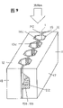
Figure 13 is the skeleton view of MIG magnetic head contour structures in the expression prior art.
In known MIG magnetic head 500 shown in Figure 13, with a pair of convex or the magnetic core of cutting 502 and 503 is oppositely arranged, they have magnetic slit 501 each other.Magnetic core 502 comprises a convex made from ferrite or to core body of cutting 504 (being designated hereinafter simply as " core body 504 ") and the thin magnetic films with high saturation magnetic flux density 506 that form on core body 504 surfaces.Equally, magnetic core 503 comprises a convex made from ferrite or to core body of cutting 505 (hereinafter to be referred as " core body 505 ") and the thin magnetic films with high saturation magnetic flux density 507 that form on core body 505 surfaces.Form thin magnetic film 506 and 507 and be to such an extent that be to cover respectively above the core body 504,505 the outstanding end face in magnetic slit 501 but also cover two side surfaces that begin thus.Be provided with unshowned nonmagnetic film among Figure 13 (being called " magnetic slit part ") in the magnetic slit 501. Magnetic core 502 and 503 docks and leaves the magnetic slit 501 that wherein is inserted with the slit part each other.In addition, Dui Jie magnetic core 502 and 503 engages each other with a pair of glass workpiece 508,509 like this, makes this be positioned at both sides, magnetic core butt end to glass workpiece.The middle part that can be located at MIG magnetic head 500 sides for the coiling mouth 510 that coil passes through.
From the viewpoint of arrow path technology, because foozle for example two magnetic cores 502 and 503 merging precision, or owing to be subjected to the influence of thin magnetic film 506 and 507 magnetic track edge circularity, above-mentioned MIG magnetic head can not reach enough precision aspect track width.And, owing to can not determine track width uniquely, so can not obtain enough precision when in assembling process, carrying out magnetic track height control step.Caused output reduction when producing MIG magnetic head 500 thus.
In order to address these problems, the application's applicant has proposed a kind of MIG magnetic head, similarly magnetic head is disclosed among the Japanese publication communique NO.7-2202218, and it is corresponding to application on September 29th, 1994 and the present U.S. Patent application S.N.08/313 that is examining, 594.In Figure 14, schematically shown the top face profiles of MIG magnetic head 600, that is, and the slidingsurface of relative tape.
The basic profile of MIG magnetic head 600 and the appearance similar of above-mentioned MIG magnetic head 500.With a pair of convex or the magnetic core of cutting 602 and 603 is oppositely arranged, they have magnetic slit 601 each other.Magnetic core 602 comprises a convex made from ferrite or the core body of cutting 604 (is designated hereinafter simply as " core body 604 ") and the thin magnetic films with high saturation magnetic flux density 606 that form on core body 604 surfaces.Equally, magnetic core 603 comprises a convex made from ferrite or to core body of cutting 605 (being designated hereinafter simply as " core body 605 ") and the thin magnetic films with high saturation magnetic flux density 607 that form on core body 605 surfaces.Form thin magnetic film 606 and 607 and be to such an extent that be to cover respectively above the core body 604,605 the outstanding end face in magnetic slit 601 but also cover two side surfaces that begin thus.Be provided with nonmagnetic film in the magnetic slit 601 as the slit part. Magnetic core 602 and 603 docks and leaves the magnetic seam 601 that wherein is inserted with the slit part each other.In addition, Dui Jie magnetic core 602 and 603 engages each other with a pair of glass workpiece 608,609 like this, makes this be positioned at the both sides of magnetic core butt end to glass workpiece.
Be provided with recess 613a and 614a on the tape slidingsurface of MIG magnetic head 600, it is crossed over except that the whole magnetic core 602 and 604 through the finished part 639 of projection, and this recess is used to regulate track width.By these recesses 613a and 614a are set, can eliminate with magnetic head 600 in magnetic core 602 magnetic track relevant with 603 merging precisions do not overlap phenomenon, and can reduce because of the magnetic track edge effectively or be called the precise decreasing that the circularity of fringe causes.
Yet, when producing MIG magnetic head 600 owing to after the step of processing recess 613a and 614a, also will carry out some processing, so may cause the magnetic track between magnetic core 602 and 603 not overlapping of slight extent to occur, and this may be the reason that can not keep original track width with enough precision.
In addition, between glass workpiece 608,609 and the magnetic book film 606,607 and be processed into convex or to the side surface of the magnetic core 602 of cutting part 639 and 603 on the anti-regeneration film 640 that do not constitute by for example silicon dioxide, zirconium dioxide, tantalum pentoxide, glass, chromium or their compound.Like this, can stop respectively between magnetic core 602,603 (more precisely magnetic book film 606,607) and the glass workpiece 608,609 chemical reaction takes place.Yet,, between thin magnetic film 606,607 and glass workpiece 608,609, this anti-regeneration film 640 is not set at recess 613a and 614a place.So between magnetic book film herein and the glass workpiece chemical reaction can take place.As a result, magnetic track edge may occur stained.
Because the problems referred to above, both having made is to adopt the MIG magnetic head 600 shown in Figure 14, also still has the problem relevant with the precision of track width.
On the other hand, in some prior arts, making some effort aspect the precision of transforming track width up to now.
For example, U.S. Patent No. 4,110,902 disclose the method that lead that a kind of utilization draws from the end face of slidingsurface is adjusted track width.This need handle whole slidingsurface concerning fixing track width.Yet, melt and the problem relevant can occur owing to join, and have the possibility that magnetic characteristic is significantly degenerated with wearing quality with the magnetic medium of operation.
United States Patent (USP) NO3,668,775 disclose a kind of magnetic head, and its structure is complementary the size of whole magnetic core and track width.Yet, both made and adopted this structure, the possibility that also still exists magnetic characteristic obviously to reduce.And, also can cause the magnetic head strength degradation.
EPO646907A2 discloses a kind of magnetic head, this magnetic head comprises a pair of by the mutual opposed convex magnetic core (12 of magnetic gap (1), 13), a pair ofly be arranged on the glass blocks (15 that the magnetic core both sides fuse together magnetic core, 16), be formed on convex magnetic core main body (17,18) thin magnetic film (19 on, 20), be formed on magnetic core main body (17,18) the coiling mouth (21) at least one, and in scope, dig at thin magnetic film (19 from the tape slipping plane of magnetic core to coiling mouthful (21), 20) recess (13a in the side, 14a), (13a is to form along the direction vertical with the track width direction 14a) to recess.But this magnetic head can fringe occur in the inside surface place between recess and front glass spare.
In addition, United States Patent (USP) NO5 discloses a kind of method of producing magnetic head in 298,113, wherein with lathe tool the magnetic track near zone is processed.Yet, in this method, might damage edge, magnetic slit.And the magnetic slit is the pith that is used for magnetic recording/reproducing on the magnetic head.This damage occurs and can cause magnetic characteristic to descend, and see it also is disadvantageous from the angle of magnetic head operating characteristic.And, from the angle of machining accuracy, be difficult to reach about 1 micron or littler machining precision.Particularly, on the direction of magnetic gap depth, be difficult to the constant machining accuracy of maintenance.
And, in disclosed method of carrying out machining with lathe tool, when implementing job operation, must push down lathe tool with respect to magnetic core for magnetic core being processed into reservation shape.The result is can't process clavate structural section material, thereby make batch process become problem.In addition, owing to add the denatured layer that on finished surface, forms man-hour magnetic characteristic is descended, so brought the problem that can not accurately keep predetermined effective track width.
Recently owing to improved the density in the magnetic recording, so need a kind of with approximately+-0.5 micron or littler precision processing track width be about 10 microns or littler magnetic head.Yet as mentioned above, it almost is impossible satisfying above-mentioned requirements with prior art under the situation that magnetic characteristic is not descended.
The objective of the invention is to propose a kind of magnetic head and manufacture method thereof that can overcome above-mentioned shortcoming.
Magnetic head of the present invention comprises: a pair of magnetic core, all have the part that is processed into convex on each magnetic core, and the said part that is processed into convex is positioned opposite to each other, can insert magnetic slit part in the middle of it; A pair of glass workpiece, it is arranged on the both sides of said a pair of magnetic core, and said a pair of magnetic core is fused together.In each of said magnetic core, on the said outstanding end face that is processed into the convex part, be formed with magnetic book film at least; Form to regulate a pair of recess of track width on the tape slidingsurface of said a pair of magnetic core, it joins from the butted part that both sides and said a pair of magnetic core are processed into convex.The shape of said a pair of recess should be able to guarantee that when said tape moves the total inner surface of two recesses can not be in the inboard, edge of recording figure forming on the tape.
Preferably, said a pair of recess is shaped as circle.More preferably, at the place, point of crossing of magnetic slit and recess, the tangent line of recess circular arc is arranged essentially parallel to the moving direction of said tape.Other or further optimal way be that the arc radius that makes said recess is less than the minimum thickness that is located at the magnetic book film on the said outstanding end face.
In one embodiment, the inside surface between said thin magnetic film and said magnetic core is arranged essentially parallel to the magnetic slit surfaces that is positioned at said outstanding end.
Preferably, between said a pair of recess and said a pair of glass workpiece, further be provided with anti-regeneration film at least.
Preferably, each in the said a pair of glass workpiece includes front glass spare that is provided with near tape slidingsurface on the magnetic head and the back glass workpiece that is provided with away from said tape slidingsurface.The softening point that is lower than said back glass workpiece that the softening point of said front glass spare is set.
In having the magnetic head of said structure, said recess preferably forms by electrodischarge machining.
Preferably, said a pair of magnetic core comprises ferrite core, is provided with magnetic book film on the surface of each ferrite core, and said a pair of recess only is formed in the said magnetic book film.
In one embodiment, magnetic head further comprises a coiling mouth that is used for winding around, and said a pair of recess extends to said coiling mouth.
The invention provides a kind of magnetic recording/reproducing apparatus that comprises magnetic head, this device comprises signal system, servo-drive system, goes up tape and coiling magnetic tape system, magnetic head, power supply and control assembly.Said magnetic head has said structure.
The present invention also provides a kind of magnetic recording/reproducing apparatus that comprises magnetic head, this device comprises signal system, servo-drive system, goes up tape and coiling magnetic tape system, magnetic head, power supply and control assembly, when this device operation, tape contacts with being installed in a magnetic head on the rotating magnetic drum that carries out spiral scan, and signal is recorded on the tape and replay signal from the tape.Said magnetic head has said structure.
Another aspect of the present invention is to provide a kind of method of making magnetic head, and wherein said magnetic head comprises: a pair of magnetic core all has the part that is processed into convex and is arranged on the metal magnetic book film that is processed on the convex outstanding end face partly at least on each magnetic core; A glass workpiece, it comprises the front glass spare that is provided with near the front surface of said magnetic core and the back glass workpiece that is provided with away from the front surface of said magnetic core.Said method comprises: the first step, said outstanding end face is docked and inserts therebetween a magnetic slit part toward each other; In second step, said a pair of magnetic core and said back glass workpiece are fused together; The 3rd step, pass through electrodischarge machining, the a pair of recess that is used to regulate track width is set on the tape slidingsurface of said a pair of magnetic core, this recess is joined from the butted part that both sides and said a pair of magnetic core are processed into the convex part, the shape of said a pair of recess should be able to guarantee that when said tape moves the total inner surface of two recesses can not be in the inboard, edge of recording figure forming on the tape; In the 4th step,, fill the groove that on the precalculated position of said magnetic core, forms in advance so that constitute front glass spare with glass material by thermal treatment.
Preferably, with the softening point that is lower than the back glass workpiece of the softening point setting of said front glass spare, the softening temperature of glass workpiece after being lower than of filling by heat that the heat treatment temperature used in the step that forms said front glass spare sets is said.
Preferably, further be included in the described the 4th and go on foot the step that prevents to take place between metal magnetic film and the said glass workpiece the anti-regeneration film of chemical reaction before at least in formation on the surface of said a pair of recess.
Preferably, forming by electrodischarge machining in the step of recess, in rotating electrode, the end by the said magnetic core of electrodischarge machining electrode pair processes.
In one embodiment, forming by electrodischarge machining in the step of said recess, processing with end, the top of the electrodischarge machining electrode that extends to coiling mouthful at least to said magnetic core.
Therefore, the advantage that foregoing invention embodied is that (1) is carried and has encircleed a kind of dynamical arrow path magnetic head, this magnetic head is applicable to the high density magnetic recording technology, (2) provide a kind of method that can produce above-mentioned arrow path magnetic head with the high yield low price, (3) provide a kind of arrow path magnetic recording/reproducing apparatus at interval that is suitable for by the method that adopts said head and production magnetic head.
To one skilled in the art, read and understand following detailed description, can be more clearly visible these and other advantage of the present invention by the reference accompanying drawing.
Fig. 1 schematically shows the skeleton view of magnetic head structure in one embodiment of the invention.
Fig. 2 schematically shows in the above embodiment of the present invention the planimetric map of tape slidingsurface structure on the magnetic head.
Fig. 3 schematically shows in the above embodiment of the present invention the zoomed-in view of slotted section structure on the magnetic head, wherein also shows the moving direction of tape.
Fig. 4 is a skeleton view of describing a step in the magnetic head manufacturing method in the above embodiment of the present invention.
Fig. 5 is another skeleton view of describing a step in the magnetic head manufacturing method in the above embodiment of the present invention.
Fig. 6 is another skeleton view of describing a step in the magnetic head manufacturing method in the above embodiment of the present invention.
Fig. 7 is another skeleton view of describing a step in the magnetic head manufacturing method in the above embodiment of the present invention.
Fig. 8 is another skeleton view of describing a step in the magnetic head manufacturing method in the above embodiment of the present invention.
Fig. 9 is another skeleton view of describing a step in the magnetic head manufacturing method in the above embodiment of the present invention.
Figure 10 is another skeleton view of describing a step in the magnetic head manufacturing method in the above embodiment of the present invention.
Figure 11 represents near the structure skeleton view of magnetic head of magnetic recording/reproducing apparatus in one embodiment of the invention.
Figure 12 is the recording figure forming diagrammatic sketch that schematically shows by on the recording medium of magnetic recording/reproducing apparatus record of the present invention shown in Figure 11.
Figure 13 is the skeleton view that schematically shows magnetic head structure in the prior art.
Figure 14 schematically shows in the prior art structural plan figure of tape slidingsurface on the another kind of magnetic head.
Embodiments of the invention are described below with reference to accompanying drawings.
Fig. 1 schematically shows the structure skeleton view of magnetic head 100 in one embodiment of the invention,
Fig. 2 schematically shows magnetic head 100 end faces, i.e. the structural plan figure of tape slidingsurface.
In magnetic head 100, a pair of positioned opposite to each other and middlely have the convex in magnetic slit 1 or the magnetic core of cutting 11 and 12 is bonded with each other and bonds together with a pair of glass workpiece.Be provided with slit part 40 (not shown in the figures) in the magnetic slit 1 referring to Fig. 2.In a pair of glass workpiece each comprises that the position is near the front glass spare 15a of tape slidingsurface on the magnetic core 11 and 12 and the position back glass workpiece 15b away from the tape slidingsurface.Equally, another in a pair of glass workpiece comprises that the position is near the front glass spare 16a of tape slidingsurface on the magnetic core 11 and 12 and the position back glass workpiece 16b away from the tape slidingsurface.
Convex magnetic core 11 comprises ferrite core 17 that constitutes the magnetic core main body and the thin magnetic film 19 with high saturation magnetic flux density, magnetic book film 19 is set in order that cover the outstanding end face that is processed into convex part 39 on the ferrite 17 and the side surface that continues from outstanding end face.Equally, convex magnetic core 12 comprises ferrite core 18 that constitutes the magnetic core main body and the thin magnetic film 20 with high saturation magnetic flux density, thin magnetic film 20 is set is to such an extent that be to cover the outstanding end face that is processed into convex part 39 on the ferrite 18 and from the side surface of outstanding end face continuity.
In addition, magnetic core 11 and 12 also comprises recess 13a and 14a, and it is in order to clamp magnetic slit 1 from both sides that recess is set.Recess 13a and 14a are shaped as arc and only are formed near the magnetic track edge the thin magnetic film 19 or 20.Recess 13a and 14a being arranged in the whole zone of magnetic core 11 and 12 makes it join from both sides and the butted part that is processed into convex part 39.When to keep magnetic head 100 top surfaces be track width on the tape slidingsurface, these recesses 13a and 14a extended to the coiling mouth 21 of the side center that is located at magnetic head 100.Also recess 13a and 14a can be designed to make it to extend to ferrite 17 and 18.
As following will according to manufacturing step describe in detail, by these recesses 13a and 14a are set, by when forming recess 13a and 14a, convex magnetic core 11 and 12 being fixed together with back glass workpiece 15b and 16b, can prevent that magnetic track edge occurs in magnetic head 100 even the butt joint of small magnitude misplace.
In addition, make the material softening point of front glass spare 15a and 16a be lower than the material softening point of back glass workpiece 15b and 16b, can further reduce the butt joint dislocation of magnetic core 11 and 12 by the structured material of selecting glass workpiece.This is because when fusion front glass spare 15a and 16a, heat treatment temperature can be set to such an extent that be lower than the temperature of back glass workpiece 15b and 16b softening point, and like this, when fusion front glass spare 15a and 16a, back glass workpiece 15b and 16b just can not soften.
And in magnetic head 100, anti-regeneration film 50 (not showing among Fig. 1, referring to Fig. 2) is arranged on the thin magnetic film 19,20 and the inside surface between the glass workpiece at recess 13a and 14a place.Can avoid thin magnetic film 19,20 directly to contact with the 14a place at recess 13a like this, thereby can prevent to take place between them chemical reaction with glass workpiece.The result who does like this is that expanding can not appear in the magnetic track edge, and the magnetic edge at magnetic track edge is very clear.
Therefore, magnetic head 100 of the present invention can be adjusted to initial value with track width Tw accurately.
Fig. 3 is the end face that schematically shows magnetic head 100, that is, the zoomed-in view of magnetic slit 1 near zone on the tape slidingsurface, arrow is wherein represented the direction of motion of tape 34.As shown in FIG., tape 34 does not move along normal direction with respect to the magnetic slit 1 of magnetic head 100, but the inclination certain angle is so that carry out azimuth recording.For the sake of simplicity, not shown thin magnetic film, anti-regeneration film and slit material in Fig. 3.
In magnetic head 100, formed circular arc recess 13a and 14a should make in the magnetic slit 1 to be arranged essentially parallel to the traffic direction of tape 34 with the circular arc tangential line at the P place, point of crossing of recess 13a and 14a.Because this structure, the peripheral part of the recording figure forming that forms on the tape 34 neither with recess 13a, 14a and front glass spare 15a, 16a between inside surface contact and also on this surface, do not move.The result is, fringe can not occur at these inside surface places, and institute is so that magnetic head 100 is suitable for carrying out magnetic recording at interval with arrow path.Can also provide a kind of suitable magnetic head of getting at the position angle under the arbitrary value situation 100 according to the present invention.The present invention also provides a kind of magnetic head of bearing null.
When forming recess 13a and 14a by electrodischarge machining and make magnetic head 100 of the present invention, can reduce the denatured layer that on finished surface, causes, and can also reduce the surfaceness of finished surface because of process.And, a kind of arrow path magnetic head that is fit to carry out high density magnetic recording that can not occur as problems such as magnetic slit damage of edges, magnetic characteristic decline, the reductions of effective track width precision is provided.In addition, above-mentioned electrodischarge machining can not make magnetic head 100 during processing structural member for example magnetic core 11 and 12 bears physical stress, so can avoid the generation of problems such as crack.On the contrary, in the cut that use lathe tool that adopts in prior art or analog carry out, the physical stress that object to be processed is for example born on the magnetic core is very high.Therefore, this processing is not suitable for carrying out above-mentioned Precision Machining.
In addition, when carrying out electrodischarge machining, sparking electrode is rotated and the sparking electrode that makes this rotation enters processed object from the side at magnetic track edge.In this way, can on the depth direction in magnetic slit 1, stablize the machining precision of track width.And, owing to used microscler sparking electrode very thin and that diameter is minimum, be that clavate can be processed too so both made processed object, realized the batch process of magnetic head 100 thus.
As mentioned above, according to the present invention, can provide a kind of output the high and low magnetic head 100 of price, there is not the magnetic track dislocation in this magnetic head and is applicable to the arrow path technology, and then can realize high density magnetic recording.Magnetic head 100 can also reduce the recording/reproducing fringe.And, by adopting this magnetic head 100.A kind of high density recording/replay device that is applicable to digital VCR can also be provided.
The material that can use as thin magnetic film 19,20 on magnetic head 100 comprises Sendust film, cobalt class non-crystal thin film, cobalt class superstructure nitrogen alloy film, iron class superstructure nitride film and iron class nitride film etc.Utilize for example evaporation, ion film plating or cathode vacuum spraying plating equal vacuum plated film formation technology, the film of being made by these materials by deposition on the surface of ferrite core 17 and 18 just can form thin magnetic film 19 and 20.
Both made in the magnetic head structure of prior art, sometimes also at the surface portion of each magnetic core rather than the anti-regeneration film that its thickness is equivalent to half magnetic gap width is set on notch part, for must be obtains anti-regeneration effect between magnetic core and front glass spare.Yet this anti-regeneration film in the prior art also plays the slit part, and this anti-regeneration film is to generate before forming recess and in the process that forms the magnetic slit.In the nearest narrow slot magnetic head with narrow magnetic gap width, therefore the thickness that is difficult to make above-mentioned anti-regeneration film, can not produce enough anti-regeneration effects greater than half of magnetic gap width.Though the problem of this and magnetic track edge swell does not have direct relation, because the inter-diffusion reaction that produces between front glass spare and the thin magnetic film can cause strength of glass to descend, thereby may reduce the output of magnetic head.
Yet,, after forming magnetic slit 1 and under the situation that structural member is separated by the slit part, form anti-regeneration film 50 according to the present invention.The result is.Can optionally select material and thickness, and can make the process of shaping have higher degree of freedom.Example is known.Because the anti-regeneration film in the prior art is necessary simultaneously as the slit part, and can cause producing stress and strain because of the thermal expansivity difference between magnetic core and the anti-regeneration film, so rupture sometimes.On the other hand, according to the present invention, can avoid this problem by material or the film thickness of suitably selecting anti-regeneration film 50.
The material that can be used as the structured material use of slit part 40 comprises silicon dioxide, zirconium dioxide, tantalum pentoxide, glass, chromium, chromium oxide.And their composition.
50 of anti-regeneration films can be arranged on the thin magnetic film 19 and 20 surface at recess 13a and 14a place.Yet, such described with reference to Figure 2, by anti-regeneration film 50 is arranged on thin magnetic film 19,20 simultaneously just on recess 13a, the 14a, can avoid the decline of the strength of glass that causes because of above-mentioned reason simultaneously.The material that can be used as the structured material use of anti-regeneration film 50 comprises silicon dioxide, zirconium dioxide, tantalum pentoxide, glass, chromium, chromium oxide, and their composition.
The manufacture method of magnetic head 100 is described below with reference to Fig. 4-Figure 10.
At first, make a pair of matrix 17 and 18 that is made of for example manganese-zinc ferrite, its surface has had the fabulous depth of parallelism and smoothness by grinding or similar processing.As shown in Figure 4, on each matrix 17 and 18, process a plurality of magnetic track groove 17a and 18a parallel to each other with emery wheel or analog.This makes in a pair of matrix 17 and 18 each all have the structure that comprises a plurality of structural members, and under completion status, each structural member that constitutes a pair of ferrite core 17 and 18 all is in the magnetic head 100.Hereinafter, the matrix corresponding with ferrite core 17 and 18 shape calls " iron oxygen core body ", and uses the reference number identical with ferrite core promptly 17,18 to mark this " iron oxygen core body ".
In the iron oxygen core body 17 and 18 at least one is provided with the winding slot 22 that can supply coil to pass through.Under completion status, magnetic track groove 17a and 18a have determined to be processed into convex or to cutting the shape of part 39 in magnetic head 100, and under completion status winding slot 22 corresponding to the coiling mouth 21 in the magnetic head 100.Below as shown in Figure 5, utilize the vacuum film forming technique, on the side surface of iron oxygen core body 17 and 18, form thin magnetic film 19,20 with high saturation magnetic flux density by deposition.So just, a pair of magnetic core array 11 and 12 have been constituted, term " magnetic core body " refers to the shape that a plurality of member constitutes as used herein, under completion status, each member is all corresponding with the magnetic core 11 and 12 in the magnetic head 100, and uses the reference number identical with magnetic core 11,12 promptly 11,12 they to be marked.
The material that can be used as the structured material use of thin magnetic film 19,20 comprises Sendust film, cobalt class non-crystal thin film, cobalt class superstructure nitrogen alloy film, iron class nitride film etc.These films form by for example evaporation of vacuum film forming technique, ion plating film, cathode vacuum spraying plating etc.
Then, be provided for forming the film shape slit part (not showing among Fig. 4-10) in magnetic slit on one or two in a pair of magnetic core array 11 and 12.Then, by this slit part is clipped in the middle, and make magnetic core array 11 and 12 opposite each other like that as shown in Figure 6.The material that can be used as slit part structured material use comprises silicon dioxide, three zirconias.Tantalum pentoxide, glass, chromium, chromium oxide and their composition.
According to the present invention, because the generation after forming magnetic seam 1 of anti-regeneration film 50, so needn't require the structured material of slit part to have the effect that suppresses the diffusion reaction between magnetic film 19,20 and front glass spare 15a, the 16a.Therefore, can use the film that is suitable as slit part structured material most, for example the film that only constitutes with silicon dioxide or golden metal.Can reduce the operation that forms the magnetic slit like this and reduce cost.And, can under fabulous condition, form the magnetic slit, the result can obtain stable electromagnetic conversion.
Then, as shown in Figure 7, back glass bar 23 is inserted in the winding slot 22, and magnetic core array 11 and 12 is joined to together by thermal treatment.Under completion status, back glass workpiece 15b and 16b that the back glass bar 23 of fusion in thermal treatment constitutes in the magnetic head 100.
Then, as shown in Figure 8, with making sparking electrode 25 enter near each magnetic track side mode, begin this a pair of magnetic core array 11 and 12 is discharged, at this moment magnetic core array is in the state that by above-mentioned thermal treatment the rear portion butted part of magnetic core and back glass workpiece 15b, 16b is fused together with back glass bar 23.Recess 13a and 14a have been formed by discharge.In this way, just can on keeping top surface, form recess 13a and the 14a that extends to winding slot 22 in the track width Tw.Forming recess 13a and 14a is in order to join from both sides and the butted part that is processed into convex part 39 in the scope of two magnetic core arrays 11 and 12.Because what use during electrodischarge machining is the cylindricality sparking electrode that rotates, so the wearing and tearing of the sparking electrode 25 that causes because of processing in discharge process are uniform.Can prevent that like this sparking electrode 25 from bending, and can make the recess 13a and the 14a of formation have fixed shape.In addition, the revolution of sparking electrode 25 can be in maximum magnitude be reduced to about 0.1 micron to 0.2 micron with the surfaceness of recess 13a and 14a.In addition, recess 13a and 14a can be processed into almost ideal circle.
In addition, preferably make the thickness t (referring to Fig. 2) of the radius R of circular recess 13a and 14a less than slit 1 place's thin magnetic film 19 and 20.Can prevent that like this recess 13a and 14a from extending to ferrite core 17 and 18.If recess 13a and 14a extend to ferrite 17 and 18, so, when requiring to reduce on ferrite core 17 and 18, to be processed into the top width of convex part along with improving constantly that arrow path is required.Will increase the possibility that magnetic characteristic is degenerated.On the other hand,, then can make recess 13a and 14a not extend to ferrite core 17 and 18, so just can avoid the problems referred to above if just form recess 13a and 14a by processing thin magnetic film 19 and 20.
The diameter that preferably makes used sparking electrode 25 is about 10 microns to about 30 microns.Thin fruit diameter is less than about 10 microns, and sparking electrode 25 can not keep enough intensity and man-hour also can occur fracture adding.On the other hand, the diameter of the employed sparking electrode 25 of thin fruit is greater than about 30 microns, so must be enough greatly as the thickness of the thin magnetic film 19,20 of processed body.Yet, owing to occur eddy current loss in the inboard of thin magnetic film 19,20 or, thisly have the thin magnetic film 19 of big thickness and 20 electromagnetic conversion characteristics descends and make because the squeezing action relevant with the shape of magnetic head 100 descends.Imprison this, require the diameter of sparking electrode 25 to be in the above-mentioned scope.
More preferably, the diameter of sparking electrode 25 is decided to be about 16 microns-Yue 18 microns comparatively suitable.This has also determined thin magnetic film 19 and 20 thickness at 1 place, magnetic slit. Magnetic book film 19 and 20 preferred thickness are about 8 microns-Yue 10 microns.
In order to produce magnetic head 100 in batches, form recess 13a and 14a by the club-shaped material shown in the manuscript 8.Specifically, tens magnetic tracks are arranged on a rod.In this case, in order to form recess 13a and 14a, sparking electrode 25 need be inserted in each narrow hole 26 and and process its side surface in each magnetic track edge.Usually, the diameter of each is about 100 microns in these narrow holes 26, is practically impossible so with lathe tool it is processed.Yet the sparking electrode 25 of diameter in above-mentioned scope can be processed the inside surface in narrow hole 26 fully.And be suitable for the batch process of magnetic head 100.
In addition, can be controlled at submicron order to Working position by sparking electrode 25.That is to say, in electrodischarge machining, when making sparking electrode 25, can itself discern the enable position of sparking electrode as sensor with sparking electrode 25 near object to be processed.Because can be after doing like this observe the current position of Continuous Tracking sparking electrode under the situation that offset do not occur 25 by microscope or analog, so electrodischarge machining is suitable for producing in batches.
And, as representing in detail among Fig. 3, because electrodischarge machining can be discerned micron-sized Working position, so can process the arc of recess 13a and 14a fully in such a way, that is, make the tangent line at arc and 1 intersection point P place, magnetic slit be arranged essentially parallel to the moving direction of tape.In addition, can constitute the track width of predetermined value accurately.
Usually, when immersing in the insulating oil, carry out electrodischarge machining to object to be processed.Also can in pure water, process.In pure water, process a back step operation that does not need to clean insulating oil, so simplified production run.
According to the present invention, when forming recess 13a and 14a, fix magnetic core array 11 and 12 with back glass workpiece 15b and 16b.Given this, the magnetic track edge can not go out out even the departing from of trace level.Then, on the surface of recess 13a that processes in a manner described shown in Fig. 9 and 14a, form anti-regeneration film (not showing among Fig. 9).Can be used as the material that forms anti-regeneration membrane material use and comprise silicon dioxide, zirconium dioxide, tantalum pentoxide, glass, chromium, chromium oxide and their composition.Usually form this film with the cathode vacuum spraying plating.
In cathode vacuum spraying plating process, only from finishing book film deposition by the anterior top surface of " direction A " Fig. 9 indication.Yet, by making this that be bonded together with proper angle with respect to sputter target magnetic core array 11 and 12 is tilted, just can on the surface of recess 13a and 14a, form and have the suitable film quality and the film of film thickness.
In addition, under good conditions, can use the plasma chemical vapor deposition method, and can replace the cathode vacuum spraying plating to form film with immersion plating or plating as the example of wet type production method as the example of dry type production method.
In Fig. 9, back glass workpiece 15b and 16b are in the bottom in the narrow hole 26 that forms between magnetic core array 11 and 12.Afterwards, in back glass workpiece 15b and the part remaining space above the 16b, fill front glass spare 15a and 16a at least by thermal treatment.When carrying out this operation, as representing in detail among Fig. 2, anti-regeneration film 50 is set on the inside surface between front glass spare 15a, the 16a of recess 13a, 14a and filling respectively.Therefore, magnetic book film 19,20 and front glass spare 15a, 16a do not react, and expanding can not appear in the magnetic track edge yet.The result is, a kind of like this magnetic head can be provided, and the magnetic at its magnetic track edge is very clear.
In addition, preferably set the softening point of front glass spare 15a and 16a to such an extent that be lower than the softening point of back glass workpiece 15b and 16b.In this case, by making glass workpiece 15a and heat treated treatment temperatures such as 16a filling, fusion and curing be set at medium temperature between the softening point of the softening point of front glass spare 15a, 16a and back glass workpiece 15b, 16b, just can under the not softening situation of back glass workpiece 15b, 16b, make front glass spare 15a, 16a fusion and curing.After finishing electrodischarge machining, just can form like this even all non-existent magnetic head 100 of micro-magnetic track dislocation with better machining precision.
And in operation shown in Figure 6, when with suitable melted material, for example low-melting glass or quartz glass when at 1 place, magnetic slit a pair of magnetic core array 11 and 12 being welded together, can obtain more stable track width.In this case, can also avoid making slit 1 impaired and stable electromagnetic conversion characteristics.
In addition, owing to form recess 13a and 14a with electrodischarge machining.So reduced the surfaceness of finished surface.Like this, when filling front glass spare 15a and 16a, help flowing of they, and reduced the bubbles volume that in front glass spare 15a and 16a, generates and can cause fault by thermal treatment.
Therefore, as shown in figure 10, the dot-and-dash line in figure is cut into magnetic core array 11 and 12 piece that separates.And winding around on each explant is so far just made magnetic head 100 of the present invention.
As mentioned above, the present invention is effective especially to narrow slot and arrow path MIG magnetic head.Yet the present invention also is applicable to only have the MIG magnetic head of thin magnetic film or the magnetic head of track width broad on a magnetic core.In both cases, owing to improved the precision of track width, so can improve output.
Figure 11 schematically shows in a specific embodiment of magnetic recording/reproducing apparatus of the present invention near the view of the structure situation magnetic head.
Be located at magnetic head 32 on the Rotational Cylindrical body 33 that is installed on the fixed leg body 36 and carry out spiral scan.Move with generation when magnetic head 32 contact keeping by the tapes 34 of cylinder 35 that tilts and 37 guiding.At tape 34 run durations, signal record is reset on tape 34 or to the signal that records on the tape.The signal of resetting is handled in signal processing circuit 38 and is made it to become stereophonic signal or video image signal.
Figure 12 schematically shows the signal pattern that is recorded on the tape 34.Shown in pattern 6, signal is to record obliquely on the tape 34, and the pattern of record and tape vertically form certain angle.Reference symbol among Figure 12 " TP " is equivalent to the track width on the tape 34.
If used the arrow path magnetic head that does not have butt joint dislocation by provided by the invention, the fuzzy magnetic track that causes in magnetic track edge because of fringe or analogue just can not appear on record surface.And the loss of data district zone of not tracer signal of " d " expression (in the Figure 12 with) between the magnetic track can appear hardly.As a result, track width Tp does not narrow down and write down bulk information on tape 34.In addition, when being installed to magnetic head 32 on the Rotational Cylindrical body 33, owing to can determine the magnetic track edge of magnetic head 32 uniquely.So can accurately adjust the height of magnetic track.
As mentioned above, according to magnetic head manufacturing method of the present invention, a magnetic core that is processed into convex in advance is docking together, and fuses together with the rear portion of glass workpiece with them.In this case, near the pair of magnetic film portion that is positioned at the magnetic slit, process a pair of recess that is used to adjust track width.In this way, the magnetic head that can provide a kind of micro-magnetic track dislocation all not have.
In addition, the recess that forms with discharge-treating method can reduce the surfaceness of finished surface, and can also prevent to produce on finished surface the denatured layer that causes because of processing.Can avoid like this occurring such as damage edge, magnetic slit, magnetic characteristic degenerate, the problems such as precise decreasing of effective track width, thereby a kind of arrow path magnetic head with fabulous serviceability can be provided.And, because electrodischarge machining can not make object to be processed bear big physical stress during processing, so can avoid occurring phenomenon such as fracture.
And the sparking electrode of introducing rotation from the side with respect to object to be processed can be stablized the machining precision of track width on the depth direction in magnetic slit.And, if use extremely thin sparking electrode, then can process bars shaped object and easily realization batch process.
As mentioned above, the invention provides a kind of magnetic head of low price high production, the arrow path skill wood that this magnetic head does not exist magnetic track problem of misalignment and this magnetic head to be applicable to realize high density magnetic recording.Owing to be provided with such magnetic head, reduced the recording/reproducing fringe.In addition, can constitute the high density recording/replay device that is applicable to digital VCR with this magnetic head.
Obviously, to those skilled in the art, under the situation that does not break away from the scope of the invention and design, can make various improvement at an easy rate.Therefore, the scope of the claim that the back added is not subjected to the restriction of instructions, but on broad sense more, constitute.
Claims (21)
1, a kind of magnetic head (100), it comprises:
A pair of magnetic core (11,12) all has the part (39) that is processed into convex on each magnetic core, the said part that is processed into convex is positioned opposite to each other, can insert magnetic slit part (40) in the middle of it;
A pair of glass workpiece (15a, b; 16a, b), it is arranged on the both sides of said a pair of magnetic core (11,12), and said a pair of magnetic core is fused together; With
In each of said magnetic core (11,12) at least at the said thin magnetic film that forms on the outstanding end face of convex part (39) that is processed into; It is characterized in that:
At said a pair of magnetic core (11,12) form a pair of recess (13a that regulates track width on the tape slidingsurface, 14a), it joins from the butted part that both sides and said a pair of magnetic core are processed into convex part (39), said a pair of recess (13a, shape 14a) should be able to guarantee that when said tape moves the total inner surface of two recesses can not be in the inboard, edge that tape (34) is gone up recording figure forming.
2, magnetic head as claimed in claim 1 is characterized in that, said a pair of recess (13a, 14a) be shaped as circle.
3, magnetic head as claimed in claim 2 is characterized in that, at the place, point of crossing of magnetic slit (1) and recess circular arc, the tangent line of recess circular arc is arranged essentially parallel to the moving direction of said tape (34).
4, magnetic head as claimed in claim 2 is characterized in that, the arc radius of said recess is less than the minimum thickness that is located at the thin magnetic film (19,20) on the said outstanding end face.
5, magnetic head as claimed in claim 1 is characterized in that, the inside surface between said thin magnetic film (19,20) and said magnetic core is arranged essentially parallel to the surface, magnetic slit (1) that is positioned at said outstanding end.
6, magnetic head as claimed in claim 1 is characterized in that, further is provided with anti-regeneration film (50) at least between said a pair of recess and said a pair of glass workpiece.
7, magnetic head as claimed in claim 1 is characterized in that, said a pair of glass workpiece (15a, b; 16a, b) in each includes front glass spare that is provided with near said tape slidingsurface on the magnetic head and the back glass workpiece that is provided with away from said tape slidingsurface, the softening point that is lower than said back glass workpiece that the softening point of said front glass spare is set.
8, magnetic head as claimed in claim 1, it is characterized in that, in the said a pair of magnetic core each all comprises ferrite core, is provided with said thin magnetic film on the surface of said each ferrite core, and said a pair of recess only is formed in the said thin magnetic film.
9, magnetic head as claimed in claim 1 is characterized in that, further comprises a coiling mouth that is used for winding around, and said a pair of recess extends to said coiling mouth.
10, magnetic head as claimed in claim 1 is characterized in that, tape moves along predetermined direction, to carry out azimuth recording.
11, a kind of magnetic recording/reproducing apparatus, this device comprise signal system, servo-drive system, go up tape and coiling magnetic tape system, magnetic head, power supply and control assembly, it is characterized in that described magnetic head comprises:
A pair of magnetic core (11,12) all has the part (39) that is processed into convex on each magnetic core, the said part that is processed into convex is positioned opposite to each other, can insert magnetic slit part (40) in the middle of it;
A pair of glass workpiece (15a, b; 16a, b), it is arranged on the both sides of said a pair of magnetic core (11,12), and said a pair of magnetic core is fused together; With
In each of said magnetic core (11,12) at least at the said thin magnetic film that forms on the outstanding end face of convex part (39) that is processed into;
Wherein, at said a pair of magnetic core (11,12) form a pair of recess (13a that regulates track width on the tape slidingsurface, 14a), it joins from the butted part that both sides and said a pair of magnetic core are processed into convex part (39), (13a, shape 14a) should be able to guarantee that when said tape moves the total inner surface of two recesses can not be in the inboard, edge that tape (34) is gone up recording figure forming to said a pair of recess.
12, magnetic recording/reproducing apparatus as claimed in claim 11 is characterized in that, further is provided with anti-regeneration film (50) at least between said a pair of recess and said a pair of glass workpiece.
13, magnetic recording/reproducing apparatus as claimed in claim 11 is characterized in that, said a pair of glass workpiece (15a, b; 16a, b) in each includes front glass spare that is provided with near said tape slidingsurface on the magnetic head and the back glass workpiece that is provided with away from said tape slidingsurface, the softening point that is lower than said back glass workpiece that the softening point of said front glass spare is set.
14, magnetic recording/reproducing apparatus as claimed in claim 11 is characterized in that, when this when operation device, tape contacts with being installed in a magnetic head on the rotating magnetic drum that carries out spiral scan, and signal is recorded on the tape and replay signal from the tape.
15, magnetic recording/reproducing apparatus as claimed in claim 11 is characterized in that, tape moves along predetermined direction, to carry out azimuth recording.
16, a kind of method of making magnetic head, said magnetic head comprises: a pair of magnetic core (11,12) all has the part (39) that is processed into convex and is arranged on the magnetic metal membrane that is processed on the convex outstanding end face partly at least on each magnetic core; Glass workpiece (15a, a b; 16a, b), it comprises the front glass spare put near the front surface of said magnetic core labour and away from the back glass workpiece that the front surface of said magnetic core is provided with, it is characterized in that wherein said method comprises:
A magnetic slit part (40) is docked and inserted therebetween to the first step toward each other with said outstanding end face;
In second step, said a pair of magnetic core and said back glass workpiece are fused together;
The 3rd step, pass through electrodischarge machining, a pair of recess (the 13a that is used to regulate track width is set on the tape slidingsurface of said a pair of magnetic core, 14a), this recess is joined from the butted part that both sides and said a pair of magnetic core are processed into the convex part, said a pair of recess (13a, shape 14a) should be able to guarantee that when said tape moves the total inner surface of two recesses can not be in the inboard, edge that tape (34) is gone up recording figure forming; With
In the 4th step,, fill the groove that on the precalculated position of said magnetic core, forms in advance so that constitute front glass spare with glass material by thermal treatment.
17, method as claimed in claim 16, it is characterized in that, be provided with the softening point of said front glass spare to such an extent that be lower than the softening point of back glass workpiece, setting to such an extent that be lower than the said softening temperature of glass workpiece afterwards filling the heat treatment temperature of using in the step that forms said front glass spare by heat.
18, method as claimed in claim 16 is characterized in that, further is included in the described the 4th and goes on foot the step that prevents to take place between metal magnetic film and the said glass workpiece the anti-regeneration film of chemical reaction before at least in formation on the surface of said a pair of recess.
19, method as claimed in claim 16 is characterized in that, forming by electrodischarge machining in the step of recess, in rotating electrode, the end of the said magnetic core of electrodischarge machining electrode pair by cylindricality processes.
20, method as claimed in claim 16 is characterized in that, is forming by electrodischarge machining in the step of said recess, processes with the end to said magnetic core, the top of the electrodischarge machining electrode that extends to coiling mouthful at least.
21, method as claimed in claim 16 is characterized in that, tape moves along predetermined direction, to carry out azimuth recording.
Applications Claiming Priority (3)
| Application Number | Priority Date | Filing Date | Title |
|---|---|---|---|
| JP11969095 | 1995-05-18 | ||
| JP119690/95 | 1995-05-18 | ||
| JP119690/1995 | 1995-05-18 |
Related Child Applications (1)
| Application Number | Title | Priority Date | Filing Date |
|---|---|---|---|
| CN00107522A Division CN1126077C (en) | 1995-05-18 | 2000-05-15 | Magnetic head and its producing method and magnetic head apparatus produced with the same method |
Publications (2)
| Publication Number | Publication Date |
|---|---|
| CN1139793A CN1139793A (en) | 1997-01-08 |
| CN1069430C true CN1069430C (en) | 2001-08-08 |
Family
ID=14767653
Family Applications (2)
| Application Number | Title | Priority Date | Filing Date |
|---|---|---|---|
| CN96105097A Expired - Fee Related CN1069430C (en) | 1995-05-18 | 1996-05-20 | Magnetic head, production method and device for using same |
| CN00107522A Expired - Fee Related CN1126077C (en) | 1995-05-18 | 2000-05-15 | Magnetic head and its producing method and magnetic head apparatus produced with the same method |
Family Applications After (1)
| Application Number | Title | Priority Date | Filing Date |
|---|---|---|---|
| CN00107522A Expired - Fee Related CN1126077C (en) | 1995-05-18 | 2000-05-15 | Magnetic head and its producing method and magnetic head apparatus produced with the same method |
Country Status (4)
| Country | Link |
|---|---|
| US (3) | US6061212A (en) |
| EP (1) | EP0743635B1 (en) |
| CN (2) | CN1069430C (en) |
| DE (1) | DE69614759T2 (en) |
Families Citing this family (3)
| Publication number | Priority date | Publication date | Assignee | Title |
|---|---|---|---|---|
| JP2000207707A (en) * | 1999-01-08 | 2000-07-28 | Hitachi Ltd | Thin film magnetic head and magnetic disk device using the same |
| JP3524421B2 (en) * | 1999-03-12 | 2004-05-10 | アルプス電気株式会社 | Magnetic head |
| WO2010038099A1 (en) * | 2008-10-01 | 2010-04-08 | Vacuumschmelze Gmbh & Co. Kg | Article for use in magnetic heat exchange, intermediate article and method for producing an article for use in magnetic heat exchange |
Citations (2)
| Publication number | Priority date | Publication date | Assignee | Title |
|---|---|---|---|---|
| JPH06295412A (en) * | 1993-04-09 | 1994-10-21 | Matsushita Electric Ind Co Ltd | Magnetic head and production of magnetic head |
| EP0646907A2 (en) * | 1993-10-04 | 1995-04-05 | Matsushita Electric Industrial Co., Ltd. | Magnetic head and producing method of the same |
Family Cites Families (23)
| Publication number | Priority date | Publication date | Assignee | Title |
|---|---|---|---|---|
| JPS4826527B1 (en) * | 1969-02-13 | 1973-08-11 | ||
| US3975608A (en) * | 1972-04-06 | 1976-08-17 | A.G. Fur Industrielle Elektronik Agie Losone B. Locarno | Method and apparatus for regulating the gap distance in electroerosin machining |
| US4110902A (en) | 1975-12-22 | 1978-09-05 | Hitachi, Ltd. | Method for manufacturing a magnetic head for video signal |
| US4425701A (en) * | 1980-10-17 | 1984-01-17 | Matsushita Electric Industrial Co., Ltd. | Methods of making magnetic recording heads |
| JPS59223924A (en) * | 1983-06-03 | 1984-12-15 | Mitsubishi Electric Corp | Production for magnetic head of narrow track width |
| EP0149509B1 (en) * | 1984-01-14 | 1991-07-31 | Ngk Insulators, Ltd. | Magnectic head core and process of manufacturing the same |
| JPS61260408A (en) * | 1985-05-14 | 1986-11-18 | Matsushita Electric Ind Co Ltd | Track working method for magnetic head |
| US4890378A (en) * | 1985-08-28 | 1990-01-02 | Canon Kabushiki Kaisha | Method for manufacturing a magnetic head core having a magnetic film |
| DE3634305A1 (en) * | 1985-10-09 | 1987-04-16 | Canon Kk | MAGNETIC HEAD |
| JPH0758527B2 (en) * | 1986-01-10 | 1995-06-21 | 株式会社日立製作所 | Magnetic head |
| JPS63205809A (en) * | 1987-02-20 | 1988-08-25 | Canon Inc | Magnetic head |
| JPH0686309B2 (en) * | 1989-02-23 | 1994-11-02 | 株式会社日立製作所 | Magnetic head, manufacturing method thereof, and magnetic recording / reproducing apparatus |
| US5022140A (en) * | 1989-03-10 | 1991-06-11 | Kabushiki Kaisha Toshiba | Method of manufacturing magnetic head |
| JP2502144B2 (en) * | 1989-03-20 | 1996-05-29 | 日本碍子株式会社 | Manufacturing method of electric discharge machining electrode for forming honeycomb die and method for manufacturing honeycomb die |
| US5222006A (en) * | 1989-06-16 | 1993-06-22 | Canon Denshi Kabushiki Kaisha | Magnetic head and core chip having a magnetic thin film |
| US5113299A (en) * | 1989-07-24 | 1992-05-12 | Pioneer Electronic Corporation | Magnetic head with improved bonding between magnetic core halves |
| US5289329A (en) * | 1989-09-27 | 1994-02-22 | Mitsubishi Denki Kabushiki Kaisha | Composite type magnetic head and magnetic recording/playback apparatus adopting the same |
| US5182690A (en) * | 1989-12-29 | 1993-01-26 | Sony Corporation | Fe-n-based soft magnetic thin films and magnetic heads using such films |
| JP2543629B2 (en) * | 1991-02-14 | 1996-10-16 | 日本碍子株式会社 | Core slider for magnetic disk device and manufacturing method thereof |
| JPH04353607A (en) * | 1991-05-31 | 1992-12-08 | Matsushita Electric Ind Co Ltd | Magnetic head and manufacture thereof |
| JPH05234014A (en) * | 1992-02-20 | 1993-09-10 | Ngk Insulators Ltd | Production of core for magnetic head |
| JPH06314408A (en) * | 1993-04-30 | 1994-11-08 | Sony Corp | Magnetic head |
| JP3083675B2 (en) * | 1993-05-06 | 2000-09-04 | 松下電器産業株式会社 | Manufacturing method of magnetic head |
-
1996
- 1996-05-15 DE DE69614759T patent/DE69614759T2/en not_active Expired - Fee Related
- 1996-05-15 EP EP96107761A patent/EP0743635B1/en not_active Expired - Lifetime
- 1996-05-15 US US08/647,675 patent/US6061212A/en not_active Expired - Fee Related
- 1996-05-20 CN CN96105097A patent/CN1069430C/en not_active Expired - Fee Related
-
1997
- 1997-01-09 US US08/782,260 patent/US5924189A/en not_active Expired - Fee Related
-
1999
- 1999-03-08 US US09/264,304 patent/US6360429B1/en not_active Expired - Fee Related
-
2000
- 2000-05-15 CN CN00107522A patent/CN1126077C/en not_active Expired - Fee Related
Patent Citations (2)
| Publication number | Priority date | Publication date | Assignee | Title |
|---|---|---|---|---|
| JPH06295412A (en) * | 1993-04-09 | 1994-10-21 | Matsushita Electric Ind Co Ltd | Magnetic head and production of magnetic head |
| EP0646907A2 (en) * | 1993-10-04 | 1995-04-05 | Matsushita Electric Industrial Co., Ltd. | Magnetic head and producing method of the same |
Also Published As
| Publication number | Publication date |
|---|---|
| EP0743635B1 (en) | 2001-08-29 |
| CN1126077C (en) | 2003-10-29 |
| US6061212A (en) | 2000-05-09 |
| DE69614759T2 (en) | 2002-06-27 |
| DE69614759D1 (en) | 2001-10-04 |
| CN1277425A (en) | 2000-12-20 |
| US6360429B1 (en) | 2002-03-26 |
| CN1139793A (en) | 1997-01-08 |
| EP0743635A1 (en) | 1996-11-20 |
| US5924189A (en) | 1999-07-20 |
Similar Documents
| Publication | Publication Date | Title |
|---|---|---|
| US3922776A (en) | Method for making narrow track ferrite core flying pads | |
| CA2241233A1 (en) | Method and apparatus for precisely dimensioning pole tips of a magnetic transducing head structure | |
| JPH0287314A (en) | Manufacture of core slider for fixed magnetic disk device | |
| CN1069430C (en) | Magnetic head, production method and device for using same | |
| KR100320709B1 (en) | Magnetic head | |
| JPS63146202A (en) | Magnetic head and its production | |
| CN1190776C (en) | Magnetic head and its manufacturing method, and magnetic recording and/or reproducing system | |
| US5905612A (en) | Magnetic head and producing method of the same | |
| CN1080424C (en) | Magnetic head and its producing method | |
| JPH04113506A (en) | Production of floating type magnetic head | |
| JPH06295412A (en) | Magnetic head and production of magnetic head | |
| JPH0935209A (en) | Magnetic head and its manufacture and magnetic recording and reproducing device using the them | |
| JPS6151335B2 (en) | ||
| JP2000020908A (en) | Magnetic head, its manufacture, and magnetic recording and reproducing device | |
| JPH10293904A (en) | Magnetic head and magnetic recording and reproducing device | |
| JPH06124561A (en) | Magnetic head slider and its production and hard disk driving device | |
| JPH10269522A (en) | Thin film magnetic head and its manufacture | |
| JP2002367109A (en) | Magnetic head for magneto-optical recording and magneto-optical recording device | |
| JPH04182905A (en) | Production of magnetic head | |
| JPH01319118A (en) | Magnetic head | |
| JPH10188211A (en) | Manufacture of magnetic head | |
| JPH02247807A (en) | Magnetic head | |
| JPH0489604A (en) | Core for composite magnetic head and manufacture of said core | |
| JPS61258313A (en) | Production of magnetic head core | |
| JPH02260209A (en) | Production of magnetic head |
Legal Events
| Date | Code | Title | Description |
|---|---|---|---|
| C10 | Entry into substantive examination | ||
| SE01 | Entry into force of request for substantive examination | ||
| C06 | Publication | ||
| PB01 | Publication | ||
| C14 | Grant of patent or utility model | ||
| GR01 | Patent grant | ||
| C19 | Lapse of patent right due to non-payment of the annual fee | ||
| CF01 | Termination of patent right due to non-payment of annual fee |