CN106935984B - Beam forming method and apparatus - Google Patents
Beam forming method and apparatus Download PDFInfo
- Publication number
- CN106935984B CN106935984B CN201710073184.8A CN201710073184A CN106935984B CN 106935984 B CN106935984 B CN 106935984B CN 201710073184 A CN201710073184 A CN 201710073184A CN 106935984 B CN106935984 B CN 106935984B
- Authority
- CN
- China
- Prior art keywords
- antenna
- antenna element
- port
- weight
- complex conjugate
- Prior art date
- Legal status (The legal status is an assumption and is not a legal conclusion. Google has not performed a legal analysis and makes no representation as to the accuracy of the status listed.)
- Active
Links
Images


Classifications
-
- H—ELECTRICITY
- H01—ELECTRIC ELEMENTS
- H01Q—ANTENNAS, i.e. RADIO AERIALS
- H01Q21/00—Antenna arrays or systems
-
- H—ELECTRICITY
- H01—ELECTRIC ELEMENTS
- H01Q—ANTENNAS, i.e. RADIO AERIALS
- H01Q3/00—Arrangements for changing or varying the orientation or the shape of the directional pattern of the waves radiated from an antenna or antenna system
- H01Q3/26—Arrangements for changing or varying the orientation or the shape of the directional pattern of the waves radiated from an antenna or antenna system varying the relative phase or relative amplitude of energisation between two or more active radiating elements; varying the distribution of energy across a radiating aperture
- H01Q3/30—Arrangements for changing or varying the orientation or the shape of the directional pattern of the waves radiated from an antenna or antenna system varying the relative phase or relative amplitude of energisation between two or more active radiating elements; varying the distribution of energy across a radiating aperture varying the relative phase between the radiating elements of an array
- H01Q3/34—Arrangements for changing or varying the orientation or the shape of the directional pattern of the waves radiated from an antenna or antenna system varying the relative phase or relative amplitude of energisation between two or more active radiating elements; varying the distribution of energy across a radiating aperture varying the relative phase between the radiating elements of an array by electrical means
- H01Q3/40—Arrangements for changing or varying the orientation or the shape of the directional pattern of the waves radiated from an antenna or antenna system varying the relative phase or relative amplitude of energisation between two or more active radiating elements; varying the distribution of energy across a radiating aperture varying the relative phase between the radiating elements of an array by electrical means with phasing matrix
-
- H—ELECTRICITY
- H01—ELECTRIC ELEMENTS
- H01Q—ANTENNAS, i.e. RADIO AERIALS
- H01Q3/00—Arrangements for changing or varying the orientation or the shape of the directional pattern of the waves radiated from an antenna or antenna system
- H01Q3/26—Arrangements for changing or varying the orientation or the shape of the directional pattern of the waves radiated from an antenna or antenna system varying the relative phase or relative amplitude of energisation between two or more active radiating elements; varying the distribution of energy across a radiating aperture
-
- H—ELECTRICITY
- H01—ELECTRIC ELEMENTS
- H01Q—ANTENNAS, i.e. RADIO AERIALS
- H01Q21/00—Antenna arrays or systems
- H01Q21/24—Combinations of antenna units polarised in different directions for transmitting or receiving circularly and elliptically polarised waves or waves linearly polarised in any direction
-
- H—ELECTRICITY
- H01—ELECTRIC ELEMENTS
- H01Q—ANTENNAS, i.e. RADIO AERIALS
- H01Q25/00—Antennas or antenna systems providing at least two radiating patterns
- H01Q25/001—Crossed polarisation dual antennas
-
- H—ELECTRICITY
- H01—ELECTRIC ELEMENTS
- H01Q—ANTENNAS, i.e. RADIO AERIALS
- H01Q3/00—Arrangements for changing or varying the orientation or the shape of the directional pattern of the waves radiated from an antenna or antenna system
- H01Q3/26—Arrangements for changing or varying the orientation or the shape of the directional pattern of the waves radiated from an antenna or antenna system varying the relative phase or relative amplitude of energisation between two or more active radiating elements; varying the distribution of energy across a radiating aperture
- H01Q3/30—Arrangements for changing or varying the orientation or the shape of the directional pattern of the waves radiated from an antenna or antenna system varying the relative phase or relative amplitude of energisation between two or more active radiating elements; varying the distribution of energy across a radiating aperture varying the relative phase between the radiating elements of an array
-
- H—ELECTRICITY
- H04—ELECTRIC COMMUNICATION TECHNIQUE
- H04B—TRANSMISSION
- H04B7/00—Radio transmission systems, i.e. using radiation field
- H04B7/02—Diversity systems; Multi-antenna system, i.e. transmission or reception using multiple antennas
- H04B7/04—Diversity systems; Multi-antenna system, i.e. transmission or reception using multiple antennas using two or more spaced independent antennas
- H04B7/0408—Diversity systems; Multi-antenna system, i.e. transmission or reception using multiple antennas using two or more spaced independent antennas using two or more beams, i.e. beam diversity
-
- H—ELECTRICITY
- H04—ELECTRIC COMMUNICATION TECHNIQUE
- H04B—TRANSMISSION
- H04B7/00—Radio transmission systems, i.e. using radiation field
- H04B7/02—Diversity systems; Multi-antenna system, i.e. transmission or reception using multiple antennas
- H04B7/04—Diversity systems; Multi-antenna system, i.e. transmission or reception using multiple antennas using two or more spaced independent antennas
- H04B7/06—Diversity systems; Multi-antenna system, i.e. transmission or reception using multiple antennas using two or more spaced independent antennas at the transmitting station
- H04B7/0613—Diversity systems; Multi-antenna system, i.e. transmission or reception using multiple antennas using two or more spaced independent antennas at the transmitting station using simultaneous transmission
- H04B7/0615—Diversity systems; Multi-antenna system, i.e. transmission or reception using multiple antennas using two or more spaced independent antennas at the transmitting station using simultaneous transmission of weighted versions of same signal
- H04B7/0617—Diversity systems; Multi-antenna system, i.e. transmission or reception using multiple antennas using two or more spaced independent antennas at the transmitting station using simultaneous transmission of weighted versions of same signal for beam forming
-
- H—ELECTRICITY
- H04—ELECTRIC COMMUNICATION TECHNIQUE
- H04B—TRANSMISSION
- H04B7/00—Radio transmission systems, i.e. using radiation field
- H04B7/02—Diversity systems; Multi-antenna system, i.e. transmission or reception using multiple antennas
- H04B7/04—Diversity systems; Multi-antenna system, i.e. transmission or reception using multiple antennas using two or more spaced independent antennas
- H04B7/08—Diversity systems; Multi-antenna system, i.e. transmission or reception using multiple antennas using two or more spaced independent antennas at the receiving station
- H04B7/0837—Diversity systems; Multi-antenna system, i.e. transmission or reception using multiple antennas using two or more spaced independent antennas at the receiving station using pre-detection combining
- H04B7/0842—Weighted combining
-
- H—ELECTRICITY
- H04—ELECTRIC COMMUNICATION TECHNIQUE
- H04B—TRANSMISSION
- H04B7/00—Radio transmission systems, i.e. using radiation field
- H04B7/02—Diversity systems; Multi-antenna system, i.e. transmission or reception using multiple antennas
- H04B7/10—Polarisation diversity; Directional diversity
Landscapes
- Engineering & Computer Science (AREA)
- Computer Networks & Wireless Communication (AREA)
- Signal Processing (AREA)
- Variable-Direction Aerials And Aerial Arrays (AREA)
Abstract
A method of creating two beams (a first beam and a second beam) using an antenna array is provided. In one aspect, the method uses dual polarization beamforming, which allows for many degrees of freedom in designing the desired power pattern. The method is well suited for systems with multiple radio chains (e.g., systems with active antennas). The method is also well suited for multi-port systems such as TD-SCDMA. In some embodiments, the method produces two beams, where (a) the shape of the power beam pattern of the first beam and the shape of the power beam pattern of the second beam are the same (or substantially the same) in multiple directions of interest, and (b) the beams have orthogonal (or substantially orthogonal) polarizations in the coverage area.
Description
Technical Field
The present invention relates to the field of beamforming.
Background
There are methods of using antenna arrays to attempt to create beams with desired beam shapes. However, in many cases, the match between the actual beam shape and the intended beam shape is poor. In addition, the power utilization obtained is often poor.
Accordingly, improved apparatus and methods for creating beams using antenna arrays are desired.
Disclosure of Invention
An antenna array for generating at least two beams (a first beam and a second beam) and a method of using the antenna array are provided. In one aspect, a method of using an antenna array employs dual polarization beamforming, which allows for many degrees of freedom in designing a desired power pattern. The method provided is well suited for systems with multiple radio chains (e.g., systems with active antennas). The method is also well suited for multi-port systems such as TD-SCDMA. In some embodiments, two beams are generated, where each beam has (a) a power pattern that is substantially the same as the other beam in multiple directions of interest (or "User Equipment (UE) coverage areas"), as opposed to only in a single direction of interest (e.g., the direction of a particular UE location), and (b) a substantially orthogonal polarization relative to the other beam in the UE coverage area. Some of the advantages obtained from implementing the method according to some embodiments of the invention include: (1) a better likelihood of achieving a beam with a pattern that matches the desired beam shape; (2) better power utilization; and (3) less sensitive to amplitude and phase errors.
In some embodiments, an antenna array apparatus is provided, wherein the antenna array apparatus comprises a first antenna element (AE1-a) and a second antenna element (AE 1-b). The first antenna element comprises a first antenna (A1) and an antenna element port (S) connected to the first antenna1a). The second antenna element comprises a second antenna (A2) and an antenna element port (T) connected to the second antenna1b). The antenna array apparatus further includes: a first beam forming circuit for directing to the port S1aApplying beam weights Wb1,S1aAnd Wb2,S1a(ii) a And a second beam forming circuit for directing the beam to the port T1bApplying beam weights Wb1,T1bAnd Wb2,T1b。
In some embodiments, Wb2,S1aIs Wb1,T1bA function of, and Wb2,T1bIs Wb1,S1aAs a function of (c). For example, Wb2,S1aMay be Wb1,T1bA function of the complex conjugate of, and Wb2,T1bIs Wb1,S1aAs a function of the complex conjugate of (a). In some embodiments, Wb2,S1aBy making a pair of Wb1,T1bThe complex conjugate of (a) is determined by phase shifting and amplitude scaling. In some embodiments, the phase shift causes a symbol offset. In some embodiments, Wb1,T1bIs offset by (β + pi.) for example, in some embodiments, Wb2,S1aEqual or substantially equal to In some embodiments, α1Is a function of the power of the signal transmitted by the first antenna and the power of the signal transmitted by the second antenna in some embodiments α1=1。
In some embodiments of the present invention, the,Wb2,T1bby mixing Wb1,S1aIs multiplied by the inverse of the amplitude scaling factor. In some embodiments, Wb2,T1bBy mixing Wb1,S1aThe complex conjugate phase shift β, for example, in some embodiments,
Wb2,T1bequal or substantially equal to 。
。
In some embodiments, the first antenna (a1) has a first polarization, the second antenna (a2) has a second polarization, and the first polarization is orthogonal (or substantially orthogonal) to the second polarization. In some embodiments, the first antenna (a1) and the second antenna (a2) have the same (or substantially the same) power pattern.
In some embodiments, the first antenna element (AE1-a) further comprises a second antenna element port (T) connected to a third antenna (A3) having a polarization and power pattern1a) And the second antenna element (AE1-b) comprises a second antenna element port (S) connected to a fourth antenna (A4) having a polarization and power pattern1b)。
In some embodiments, the antenna array apparatus further comprises: a third beam forming circuit for directing the beam to the port S1bApplying beam weights Wb1,S1bAnd Wb2,S1b(ii) a And a fourth beam forming circuit for directing the beam to the port T1aApplying beam weights Wb1,T1aAnd Wb2,T1a。
In some embodiments, Wb2,S1bIs Wb1,T1aA function of, and Wb2,T1aIs Wb1,S1bAs a function of (c). For example, Wb2,S1bMay be Wb1,T1aA function of the complex conjugate of, and Wb2,T1aIs Wb1,S1bAs a function of the complex conjugate of (a). In some embodiments, Wb2,S1bBy making a pair of Wb1,T1aThe complex conjugate of (a) is determined by phase shifting and amplitude scaling. In some embodiments, the phase shift causes a symbol offset. In some embodiments, Wb1,T1aThe complex conjugate of (d) is shifted by pi. For example, in some embodiments, Wb2,S1bIs equal to orIs substantially equal to In some embodiments, α2Is a function of the power of the signal transmitted by the third antenna and the power of the signal transmitted by the fourth antenna in some embodiments α2=1。
In some embodiments, the polarization of the first antenna (a1) is orthogonal (or substantially orthogonal) to the polarization of the third antenna (A3), the polarization of the fourth antenna (a4) is orthogonal (or substantially orthogonal) to the polarization of the second antenna (a2), and the third antenna (A3) and the fourth antenna (a4) have the same (or substantially the same) power pattern.
In some embodiments, the antenna array apparatus further comprises a third antenna element (AE2-a) and a fourth antenna element (AE2-b) together forming a second pair of antenna elements (AE2-a, AE2-b), wherein the third antenna element (AE2-a) comprises an antenna element port (S) connected to the fifth antenna (a5)2a) And the fourth antenna element (AE2-b) comprises an antenna element port (T) connected to the sixth antenna (A6)2b). In this embodiment, the antenna array apparatus may further include: a fifth beam forming circuit for directing the beam to the port S2aApplying beam weights Wb1,S2aAnd Wb2,S2a(ii) a And a sixth beamforming circuit for directing the beam to port T2bApplying beam weights Wb1,T2bAnd Wb2,T2b。
In some embodiments, Wb2,S2aIs Wb1,T2bA function of, and Wb2,T2bIs Wb1,S2aAs a function of (c). For example, Wb2,S2aMay be Wb1,T2bA function of the complex conjugate of, and Wb2,T2bIs Wb1,S2aAs a function of the complex conjugate of (a). In some embodiments, Wb2,S2aBy making a pair of Wb1,T2bThe complex conjugate of (a) is determined by phase shifting and amplitude scaling. In some embodiments, the phase shift causes a symbol offset. In some embodiments, Wb1,T2bThe complex conjugate of (d) is shifted by pi. For example, in some embodiments, Wb2,S2aEqual or substantially equal to And Wb2,T2bEqual or substantially equal to
 。
。
In some embodiments, the first and second antenna elements are symmetrically positioned about the point of symmetry, and the third and fourth antenna elements are symmetrically positioned about the point of symmetry.
In some embodiments, the shape of the power beam pattern of the first beam and the shape of the power beam pattern of the second beam are the same or substantially the same in the plurality of directions of interest, and the first beam and the second beam have orthogonal or substantially orthogonal polarizations in the coverage area.
In some embodiments, the antenna array apparatus further comprises a processor configured to determine Wb2,S1aAnd Wb2,T1bThe weight determining unit of (1). In some embodiments, the weight determination unit is configured to determine W byb2,S1a: to obtain Wb1,T1bComplex conjugate of (a) to Wb1,T1bIs phase shifted or (b) W is phase shiftedb1,T1bIs multiplied by an amplitude scaling factor, thereby producing Wb1,T1bIs scaled by the complex conjugate, and W is scaledb1,T1bThe complex conjugate of the amplitude scaling is phase shifted. In some embodiments, the weight determination unit is configured to determine W byb2,T1b: to obtain Wb1,S1aIs complex conjugated, and W isb1,S1aIs multiplied by the inverse of the amplitude scaling factor. In some embodiments, the weight determination unit is configured to determine W byb2,S1a: to Wb1,T1bIs phase shifted, thereby generating Wb1,T1bIs complex conjugated and W isb1,T1bThe complex conjugate of the phase shift is multiplied by an amplitude scaling factor. In some embodiments, the weight determination unit is configured to determine the weight by determining Wb1,T1bComplex conjugate phase shift of pi, to Wb1,T1bThe complex conjugate of (a) is phase shifted.
In another aspect, a method for creating two beams (a first beam and a second beam) is provided. In some embodiments, the method comprises: creating the first beam and the second beam using an array antenna, wherein the array antenna comprises: a first antenna element (AE1-a) and a second antenna element (AE1-b) together forming a pair of antenna elements (AE1-a, AE1-b), the first antenna element (AE1-a) comprising an antenna element port (S1) connected to a first antenna (A1)1a) And the second antenna element (AE1-b) comprises an antenna element port (T) connected to the second antenna (A2)1b). In some embodiments, the step of creating the first beam and the second beam using an antenna array comprises: to antenna element port S1aApplying beam weights Wb1,S1aAnd Wb2,S1aAnd to the antenna element port T1bApplying beam weights Wb1,T1bAnd Wb2,T1b. In some embodiments, Wb2,S1aEqual or substantially equal to And Wb2,T1bEqual or substantially equal to
 。
。
The above and other aspects and embodiments are described below with reference to the drawings.
Drawings
The accompanying drawings, which are incorporated herein and form a part of the specification, illustrate various embodiments of the present invention and, together with the description, further serve to explain the principles of the invention and to enable a person skilled in the pertinent art to make and use the invention. In the drawings, like reference numbers indicate identical or functionally similar elements.
Fig. 1 illustrates an example antenna array.
Fig. 2 further illustrates the first portion of the example antenna array.
Fig. 3 further illustrates a second portion of the example antenna array.
Fig. 4 further illustrates a third portion of the example antenna array.
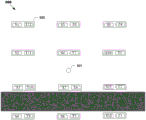
Fig. 5 illustrates an example two-dimensional antenna array.
Fig. 6A and 6B are graphs showing beam power patterns.
Fig. 7A and 7B are graphs showing beam power patterns.
Fig. 8 is a graph showing that the polarizations of the two beams are orthogonal in all directions.
FIG. 9 is a flow diagram illustrating a process according to one embodiment of the invention.
Fig. 10 is a flow diagram illustrating a process for determining beam weights according to one embodiment of the invention.
Fig. 11 shows a weight determination unit according to an embodiment of the invention.
Detailed Description
Described herein are embodiments of an antenna array apparatus that can be used to create two beams (a first beam and a second beam), where (a) the shape of the power beam pattern of the first beam and the shape of the power beam pattern of the second beam are the same or substantially the same in multiple directions of interest (or UE coverage areas), as opposed to only in a single direction of interest, and (b) each beam has an orthogonal or substantially orthogonal polarization in the UE coverage area relative to the other beam.
In some embodiments, the antenna array comprises one or more of: (1) a pair of single-port elements that may be symmetrically positioned about a point of symmetry of the antenna array, (2) a pair of dual-port antenna elements that may be symmetrically positioned about a point of symmetry of the antenna array, and/or (3) a single dual-port antenna element that may be centered about the point of symmetry.
Fig. 1 shows an example of such an antenna array apparatus 100. The example antenna array apparatus 100 includes: (1) a pair of dual port antenna elements (i.e., antenna elements AE1-a and AE 1-b); (2) a pair of single port antenna elements (i.e., antenna elements AE2-a and AE 2-b); and (3) a single dual port antenna element AE 3. As shown in fig. 1, antenna element pair AE1-a, AE1-b and antenna element pair AE2-a, AE2-b are each positioned symmetrically (or substantially symmetrically) about a point of symmetry 104 of antenna array apparatus 100. That is, for example, each antenna of antenna element AE1-a (i.e., antennas a1 and A3 — see fig. 2) and the corresponding antenna of antenna element AE1-b (i.e., antennas a2 and a4, respectively) are equidistant from symmetry point 104, a line drawn from the phase center of antenna a1 to the phase center of antenna a2 passes through symmetry point 104, and a line drawn from the phase center of antenna A3 to the phase center of antenna a4 passes through symmetry point 104. Likewise, the antenna of antenna element AE2-a (i.e., antenna a5 — see fig. 3) and the antenna of antenna element AE2-b (i.e., antenna a6) are equidistant from symmetry point 104, and a straight line drawn from the phase center of antenna a5 to the phase center of antenna a6 passes through symmetry point 104. Antenna element AE3 is centered at symmetry point 104 (e.g., the phase center of the antenna of element AE3 is equidistant from the symmetry point and a line drawn from the phase center of the antenna passes through symmetry point 104).
As further shown in fig. 1, antenna elements AE1-a, AE1-b, and AE3 each have two ports: an "S" port and a "T" port. More specifically, antenna element AE1-a has ports S1a and T1a, antenna element AE1-b has ports S1b and T1b, and antenna element AE3 has ports S3 and T3. As also shown in fig. 1, antenna elements AE2-a and AE2-b each have a single port. Antenna element AE2-a has a single S-port (S2a) and antenna element AE2-b has a single T-port (T2 b).
Although the antenna array apparatus 100 may be considered a two-dimensional antenna array, the invention is not so limited. The antenna array apparatus 100 may be a1, 2 or 3 dimensional array.
Fig. 2 further illustrates a portion of the antenna array apparatus 100. That is, fig. 2 further illustrates antenna elements AE1-a and AE1-b and beam forming circuits 201 and 204 of antenna array apparatus 100. As shown in fig. 2, the antenna element ports of antenna elements AE1-a, b are electrically connected to the antenna. Specifically, antenna unit port S1a is connected to antenna A1, antenna unit port T1a is connected to antenna A3, antenna unit port S1b is connected to antenna A4, and antenna unit port T1b is connected to antenna A2.
The structure of the antennas a1-a4 is not critical. For example, antennas A1-A4 may consist of a single radiating element, or may include multiple radiating elements, and so forth. Additionally, while the antennas within antenna elements AE1-a and AE1-b are shown as being spaced apart, this is not required. However, in some embodiments, certain characteristics of antennas A1-A4 are important. For example, in some embodiments, antenna a1 may have any polarization, but antennas a2 and A3 each have a polarization that is orthogonal or substantially orthogonal to the polarization of antenna a1, and antenna a4 has a polarization that is orthogonal or substantially orthogonal to the polarization of antennas a2 and A3. Similarly, in some embodiments, the power pattern of antenna a1 is the same or substantially the same as the power pattern of antenna a2, and the power pattern of antenna A3 is the same or substantially the same as the power pattern of antenna a 4.
As shown in fig. 2, the respective antenna element ports of antenna elements AE1-a and AE1-b are connected to beamforming circuitry. In some embodiments, as shown, the beamforming circuits 201 and 204 have the same basic structure. In the illustrated embodiment, each beamforming circuit includes: a first multiplier 221 connected to a first beam port ("beam port 1") of the antenna array apparatus 100 for multiplying a signal injected into beam port 1 of the antenna array with a beam weight (e.g., a complex beam weight) associated with the first beam; a second multiplier 222 connected to a second beam port ("beam port 2") of the antenna array apparatus 100 for multiplying the signal injected into beam port 2 of the antenna array with the beam weight associated with the second beam; and a combiner 223 connected to the antenna element ports for combining the outputs of the multipliers 221, 222 and providing the resulting combined signal to the antenna element port to which the combiner 223 is connected. As also shown, a beamforming circuit (e.g., beamforming circuit 201) may be connected to an antenna element port through one or more circuit elements (e.g., amplifier 224 and/or other circuit elements, such as signal processing elements). The beamforming circuit 201 and 204 may be implemented using signal processing elements such as Digital Signal Processors (DSPs) or other processors such as Application Specific Integrated Circuits (ASICs), microprocessors. In the illustrated embodiment, two beam weights are assigned to each antenna element port S1a, S1b, T1a, and T1b-a beam weight W of the first beamb1And a beam weight W of the second beamb2-applied to the antenna element port. More specifically, the beam weight Wb1,S1aAnd Wb2,S1aApplied to antenna element port S1a, weighting W the beamb1,T1aAnd Wb2,T1aApplied to antenna element port T1a, weighting W the beamb1,S1bAnd Wb2,S1bApplied to antenna element port S1b, and beam weight Wb1,T1bAnd Wb2,T1bApplied to antenna element port T1 b.
In some embodiments, W for a particular S antenna element port of a particular antenna elementb2The beam weight is W for the T antenna element port corresponding to a particular S antenna element port (also referred to as a "corresponding" T port)b1A function of beam weights-the corresponding T antenna element port is the T antenna element port of the antenna element paired with the particular antenna element including the particular S antenna element port. Similarly, W for a particular T antenna element port of a particular antenna elementb2The beam weight is W for the S antenna element port (i.e., the S antenna element port of the antenna element paired with the particular antenna element including the particular T antenna element port)b1A function of beam weights. For example,


in some embodiments, Wb2,SxaAnd Wb2,SxbMay be W respectivelyb1,TxbAnd Wb2,TxaAs a function of the complex conjugate of (a). Similarly, Wb2,TxaAnd Wb2,TxbMay be W respectivelyb1,SxbAnd Wb2,SxaAs a function of the complex conjugate of (a). In some embodiments, Wb2,SxaAnd Wb2,SxbBy respectively pairing Wb1,TxbAnd Wb1,TxaThe complex conjugate of (a) is determined by phase shifting and amplitude scaling. In some embodiments, the phase shift causes a symbol offset. In some embodiments of the present invention, the,w is to beb1,T1bIs offset by β + pi, and Wb1,T1aIn some embodiments, W is offset by β + pib2,TxaAnd Wb2,TxbRespectively pass through the pair Wb1,SxbAnd Wb1,SxaThe complex conjugate of (a) is determined by amplitude scaling.
In some embodiments of the present invention, the substrate may be,
F1(Wb1,Tx) Equal or substantially equal to And an
F2(Wb1,Sx) Equal or substantially equal to Wherein, in the step (A),
(Wb1,Sx)*is Wb1,SxComplex conjugation of (W)b1,Tx)*Is Wb1,TxComplex conjugate of, and α1Is the amplitude scaling factor.
In some embodiments, the value of β ranges from 0 to 2 π, 0 being preferred, the value α assuming equal input power on the two antenna element ports1May be a function of the power of the signal transmitted by the antenna connected to the corresponding antenna element port. Thus, for example, in Wb2,S1aEqual or substantially equal to α in the equation1Is the power of the signal transmitted by antenna A2 in direction (d) (i.e., P (d))A2) And the power of the signal transmitted by antenna a1 in direction d (i.e., (p), (d)A1) α in some embodiments1Equal or substantially equal to
 In many cases, in fact α1=1。
In the above exemplary embodiment, W of the port shown in FIG. 2b2The vector of beam weights is as follows:
Wb2,S1aequal or substantially equal to ,
,
Wb2,S1bEqual or substantially equal to ,
,
Wb2,T1aEqual or substantially equal to And an
Wb2,T1bEqual or substantially equal to 。
。
Fig. 3 further illustrates another portion of the antenna array apparatus 100. That is, fig. 3 further illustrates antenna elements AE2-a and AE2-b, and illustrates beam forming circuits 301 and 302 of antenna array apparatus 100. As shown in fig. 3, the antenna element ports of antenna elements AE2-a and AE2-b are electrically connected to the antenna. Specifically, antenna element port S2a is connected to antenna a5, and antenna element port T2b is connected to antenna a 6. The structure of the antennas a5-a6 is not critical. However, in some embodiments, certain characteristics of antennas A5-A6 are important. For example, in some embodiments, antenna a5 may have any polarization, but antenna a6 has a polarization that is orthogonal, or substantially orthogonal, to the polarization of antenna a 5. Similarly, in some embodiments, the power pattern of antenna a5 is the same or substantially the same as the power pattern of antenna a 6.
As shown in FIG. 3, each antenna element port of antenna elements AE2-a and AE2-b is connected to beamforming circuitry for applying two beam weights (W for beam 1) to the antenna element portsb1Beam weight and W for beam 2b2Beam weight). More specifically, the beam weight Wb1,S2aAnd Wb2,S2aApplied to antenna element port S2a, and beam weight Wb1,T2bAnd Wb2,T2bApplied to skyLine unit port T2 b.
As described above, in some embodiments, W for a particular S antenna element port of a particular antenna elementb2The beam weight being W for a port of a T antenna elementb1A function of beam weights. Similarly, W for a particular T antenna element port of a particular antenna elementb2The beam weight being W for the S antenna element portb1A function of beam weights.
In the above exemplary embodiment, W of the antenna unit port shown in fig. 3b2The beam weights are as follows:
Wb2,S2aequal or substantially equal to ,
,
Wb2,T2bEqual or substantially equal to 。
。
Fig. 4 shows antenna element AE3, and shows beamforming circuits 401 and 402 of antenna array apparatus 100, in accordance with some embodiments. As shown in fig. 4, each port of antenna element AE3 is electrically connected to an antenna. Specifically, antenna element port S3 is connected to antenna a7, and antenna element port T3 is connected to antenna a 8. The structure of the antennas a7-A8 is not critical. However, in some embodiments, certain characteristics of antennas A7-A8 are important. For example, in some embodiments, antenna a7 may have any polarization, but antenna A8 has a polarization that is orthogonal, or substantially orthogonal, to the polarization of antenna a 7. Similarly, in some embodiments, the power pattern of antenna a7 is the same or substantially the same as the power pattern of antenna A8.
As shown in fig. 4, each antenna element port of antenna element AE3 is connected to beamforming circuitry for applying two beam weights (one for beam 1 and one for beam 2) to the antenna element port. More specifically, the beam weight Wb1,S3And Wb2,S3Applied to antenna element port S3, and beam weight Wb1,T3And Wb2,T3Applied to skyLine unit port T3.
As described above, in some embodiments, W for a particular S antenna element port of a particular antenna elementb2The beam weight being W for a port of a T antenna elementb1Function of beam weights, and W for a particular T antenna element port for a particular antenna elementb2The beam weight being W for the S antenna element portb1A function of beam weights. In the above exemplary embodiment, W of the antenna unit port shown in fig. 4b2The beam weights are as follows:
Wb2,S3equal or substantially equal to ,
,
Wb2,T3Equal or substantially equal to 。
。
Referring now to fig. 5, fig. 5 illustrates an example two-dimensional antenna array 500 for forming two beams (a first beam and a second beam), wherein (a) the shape of the power beam pattern of the first beam and the shape of the power beam pattern of the second beam are the same or substantially the same in multiple directions, and (b) each beam has an orthogonal or substantially orthogonal polarization relative to the other beam in a UE coverage area. In this example, all antenna elements 502 of antenna array 500 are dual port antenna elements having S and T antenna ports. The indices used to name S antenna ports and T antenna ports are arbitrary, but, as will be seen below, the naming scheme used in fig. 5 has the advantage of making it easy to show the relationship between the beam weights.
The antenna array 500 has six pairs of antenna elements. That is, each of the 12 antenna elements 502 of the antenna array 500 is paired with another antenna element. More specifically, antenna unit 502 with port Sx (where x <7) is paired with antenna unit 502 with port Sy, where y = 13-x. Thus, for example, an antenna element having ports S1 and T12 is paired with an antenna element having ports S12 and T1. The antenna array 500 also has a point of symmetry 501. In the exemplary embodiment shown, each pair of antenna elements is positioned symmetrically about a point of symmetry 501.
Although not shown, the antenna array 500 includes beamforming circuitry for each antenna element port. As described above, each beamforming circuit is configured to apply two beam weights, the beam weight W of the first beam, to the antenna element port to which the beamforming circuit is connectedb1And a beam weight W of the second beamb2。
W for the ports shown in FIG. 4 using the same beam weight rules as described aboveb2The vector of beam weights is as follows:
Wb2,Sxequal or substantially equal to ,
,
Wb2,TxEqual or substantially equal to Wherein x =1,2, …, 12.
Example Beam Pattern
An example antenna array for generating an example beam pattern is a four-column antenna array with five dual-port antenna elements per column. The column spacing is 0.5 wavelength and the spacing within a column is 0.847 wavelength. All antenna elements are identical, with perfectly orthogonal polarizations in all directions (at least those of interest). The weight vector of the first beam (B1) contains 40 complex beam weights. For elevation domain beamforming, the beam weights applied to the S-ports, i.e., the same weights in columns 1 through 4, are found here as follows:

for azimuth beamforming, the weights applied to the S-ports, i.e., the same weights for all 5 ports in the column, are found as follows:

the total weight for the S-port is found by multiplying these weight vectors according to:

resulting in a matrix with 20 (5 rows by 4 columns) elements. This matrix can then be vectorized by taking weights column by column, forming a column vector with 20 elements.
The weight applied to the T-port is found in a similar manner. For elevation domain beamforming, the weights applied to columns 1 through 4 are again the same and are found here as follows:

for azimuth beamforming, the weights applied to the T-ports, i.e., the same weights for all 5 elements in the column, are found as follows:

the total weight of the T-ports is found by multiplying these weight vectors according to:

finally, the total weight vector for beam 1, which contains 40 elements, is found as follows:

the weight vector of the second beam is found by applying the above method, and where β is set to 0 and α is set to 1.
Fig. 6A, 6B show the power patterns of beams 1 and 2, respectively, across the azimuth of the beam peak. As can be seen from fig. 6A-6B, the beams have the same power pattern. Fig. 7A, 7B show the power patterns of beams 1 and 2, respectively, across the elevation of the beam peak. As can be seen from the figure, the beams have the same power pattern. Fig. 8 shows that the polarizations of beams 1 and 2 are orthogonal in all directions.
Fig. 9 is a flow diagram illustrating a process 900 for generating a first beam (beam 1) and a second beam (beam 2) using an antenna array. Process 900 begins at step 902, where a beam weight vector for beam 1 is selected (each of the beam weights in the beam weight vector for beam 1 is associated with an antenna element port of an antenna array). At step 904, the selected beam weight vector for beam 1 is used to determine a beam weight vector for beam 2 (each beam weight in the beam weight vector for beam 2 is associated with one of the antenna element ports). At step 906, for each beam weight in the beam weight vector for beam 1, the beam weight is applied to its associated antenna element port. At step 908, for each beam weight in the beam weight vector for beam 2, the beam weight is applied to its associated antenna element port. In some embodiments, the beam weight of beam 1 is applied to the antenna element ports by multiplying the beam weight of beam 1 with a signal injected into beam port 1 of the antenna array using beamforming circuitry connected to the antenna element ports, and the beam weight of beam 2 is applied to the antenna element ports by multiplying the beam weight of beam 2 with (i) a signal injected into beam port 2 of the antenna array or (ii) a signal injected into beam port 1 of the antenna array using beamforming circuitry configured to provide the resulting signal to the antenna element ports (e.g., see fig. 2).
Referring now to fig. 10, fig. 10 illustrates a process 1000 for determining beam weights for beam 2 associated with a selected antenna element port. Process 1000 may begin at step 1002, where an antenna element port is selected (e.g., antenna element S is selected)1a). At step 1004, an antenna unit port that is paired with the selected antenna unit port is determined. For example, if antenna element port S is selected at step 10021aThen the antenna unit port T is determined in step 10041bBecause that isAnd antenna unit port S1aA paired port. At step 1006, the beam 1 beam weight associated with the antenna element port of the selected antenna element port pair is obtained. At step 1008, the complex conjugate of the beam weight obtained at step 1006 is obtained. At step 1010, the resulting complex conjugate is phase shifted. In step 1012, the phase-shifted complex conjugate is multiplied by an amplitude scaling factor. In some embodiments, the resulting complex conjugate is multiplied by a scaling factor before being phase shifted.
Referring now to fig. 11, fig. 11 shows a block diagram of a weight determination unit 1101 according to some embodiments of the present invention. As shown in fig. 11, the weight determination unit 1101 may include: a data processing system 1102, which may include one or more processors (e.g., microprocessor, DSP) and/or one or more circuits such as an Application Specific Integrated Circuit (ASIC), Field Programmable Gate Array (FPGA), or the like; and a data storage system 1106, which may include one or more non-volatile storage devices and/or one or more volatile storage devices (e.g., Random Access Memory (RAM)). As shown, the data storage system 1106 may be used to store a beam weight vector for a first beam (beam 1). In embodiments where the data processing system 1102 includes a microprocessor, Computer Readable Program Code (CRPC)1143 can be stored in a computer readable medium 1142, such as, but not limited to, magnetic media (e.g., hard disk), optical media (e.g., DVD), memory devices (e.g., random access memory), and the like. In some embodiments, the computer readable program code 1143 is configured such that, when executed by a processor, the code 1143 causes the routing weight determination unit 1101 to perform the steps described above (e.g., the steps described above with reference to the flow chart shown in fig. 10). In other embodiments, weight determination unit 1101 is configured to perform the above steps without code 1143. That is, for example, data processing system 1102 may consist only of one or more ASICs. Accordingly, certain features of the invention described above may be implemented in hardware and/or software. For example, in particular embodiments, the functional components of the weight determination unit 1101 described above may be implemented by the data processing system 1102 executing the computer instructions 1143, by the data processing system 1102 operating independently of any computer instructions 1143, or by any suitable combination of hardware and/or software.
While various embodiments of the present invention have been described above, it should be understood that they have been presented by way of example only, and not limitation. Thus, the breadth and scope of the present invention should not be limited by any of the above-described exemplary embodiments. Moreover, any combination of the above-described elements in all possible variations thereof is encompassed by the invention unless otherwise indicated herein.
Additionally, although the methods described above and/or illustrated in the figures include a sequence of steps, this is done for ease of illustration only.
Accordingly, it is contemplated that certain steps may be added, certain steps may be omitted, the order of the steps may be rearranged, and certain steps may be performed in parallel.
Claims (21)
1. A method for creating two beams, a first beam and a second beam, the method comprising:
creating the first beam and the second beam using an antenna array, wherein,
the antenna array includes: a first antenna element (AE1-a) and a second antenna element (AE1-b) together forming a pair of antenna elements (AE1-a, AE1-b), the first antenna element (AE1-a) comprising an antenna element port S connected to a first antenna (A1)1aAnd said second antenna element (AE1-b) comprises an antenna element port T connected to a second antenna (A2)1b(ii) a It is characterized in that the preparation method is characterized in that,
the step of creating the first beam and the second beam using the antenna array comprises:
to antenna element port S1aApplying a beam weight W of the first beamb1,S1aAnd a beam weight W of said second beamb2,S1a(ii) a And
to antenna element port T1bApplying a beam weight W of the first beamb1,T1bAnd a beam weight W of said second beamb2,T1bWherein, in the step (A),
Wb2,S1ais Wb1,T1bA function of, and
Wb2,T1bis Wb1,S1aAs a function of (c).
2. The method of claim 1, wherein,
Wb2,S1ais Wb1,T1bIs a function of the complex conjugate of, and
Wb2,T1bis Wb1,S1aAs a function of the complex conjugate of (a).
3. The method of claim 2, further comprising determining Wb2,S1aWherein, in the step (A),
determining Wb2,S1aComprises (a) a step of subjecting W tob1,T1bIs phase shifted, or (b) W is phase shiftedb1,T1bIs multiplied by an amplitude scaling factor, thereby producing Wb1,T1bIs scaled by the complex conjugate, and W is scaledb1,T1bThe complex conjugate of the amplitude scaling is phase shifted.
4. The method of claim 3, wherein,
determining Wb2,s1aComprises the step of aligning Wb1,T1bIs phase shifted and W is shiftedb1,T1bIs multiplied by the amplitude scaling factor.
5. The method of claim 4, wherein the step of phase shifting comprises phase shifting by pi.
6. The method of claim 1, wherein,
Wb2,S1ais equal to And an
Wb2,T1bIs equal to ,
,
α therein1Is the amplitude scaling factor and β is the phase shift.
7. The method of claim 6, wherein α1=1 and β = 0.
8. The method of claim 6, wherein α1Is a function of the power of the signal transmitted by the first antenna and the power of the signal transmitted by the second antenna.
9. The method of claim 1, wherein,
the first antenna element (AE1-a) comprises a second antenna element port T connected to a third antenna (A3) having a polarization and power pattern1a;
The second antenna element (AE1-b) comprises a second antenna element port S connected to a fourth antenna (A4) having a polarization and power pattern1bAnd an
The step of creating the first beam and the second beam using the antenna array further comprises:
to antenna element port T1aApplying a beam weight W of the first beamb1,T1aAnd a beam weight W of said second beamb2,T1a(ii) a And
to antenna element port S1bApplying a beam weight W of the first beamb1,S1bAnd a beam weight W of said second beamb2,S1bWherein, in the step (A),
Wb2,S1bis Wb1,T1aIs a function of the complex conjugate of, and
Wb2,T1ais Wb1,S1bAs a function of the complex conjugate of (a).
10. The method of claim 9, further comprising:
determining Wb2,S1b(ii) a And
determining Wb2,T1aWherein, in the step (A),
determining Wb2,S1bComprises (a) a step of subjecting W tob1,T1aIs phase shifted, or (b) W is phase shiftedb1,T1aIs multiplied by an amplitude scaling factorThereby generating Wb1,T1aIs scaled by the complex conjugate, and W is scaledb1,T1aIs phase shifted by scaling the complex conjugate of the amplitude, and
determining Wb2,T1aComprises determining Wb1,S1bComplex conjugation of (a).
11. The method of claim 9, wherein,
the polarization of the first antenna (A1) is orthogonal to the polarization of the third antenna (A3),
the polarization of the fourth antenna (A4) is orthogonal to the polarization of the second antenna (A2), an
The third antenna (A3) and the fourth antenna (A4) have the same power pattern.
12. The method of claim 1, wherein,
the antenna array further comprises a third antenna element (AE2-a) and a fourth antenna element (AE2-b) together forming a second pair of antenna elements (AE2-a, AE2-b), wherein the third antenna element (AE2-a) comprises an antenna element port S connected to a fifth antenna (A5)2aAnd said fourth antenna element (AE2-b) comprises an antenna element port T connected to a sixth antenna (A6)2bAnd an
The step of creating the first beam and the second beam using the antenna array further comprises:
to antenna element port S2aApplying a beam weight W of the first beamb1,S2aAnd a beam weight W of said second beamb2,S2a(ii) a And
to antenna element port T2bApplying a beam weight W of the first beamb1,T2bAnd a beam weight W of said second beamb2,T2bWherein, in the step (A),
Wb2,S2ais W phase shifted by pi + βb1,T2bA function of the complex conjugate of; and
Wb2,T2bis W phase shifted βb1,S2aIs a function of the complex conjugate of (a),
where β is the phase shift.
13. The method of claim 12, wherein the antenna array is a two-dimensional antenna array.
14. The method of claim 12, wherein,
the first antenna element and the second antenna element are symmetrically positioned about a point of symmetry of the antenna array, an
The third antenna element and the fourth antenna element are symmetrically positioned about the point of symmetry.
15. The method of claim 1, wherein (a) a shape of a power beam pattern of the first beam and a shape of a power beam pattern of the second beam are the same in a plurality of directions of interest, and (b) the first beam and the second beam have orthogonal polarizations in a coverage area.
16. An antenna array apparatus comprising:
a first antenna element comprising a first antenna (A1) and an antenna element port S connected to the first antenna (A1)1a(ii) a And
a second antenna element comprising a second antenna (A2) and an antenna element port T connected to the second antenna (A2)1b,
Characterized in that the antenna array device further comprises:
a first beam forming circuit configured to direct the beam to the port S1aApplying a beam weight W of a first beamb1,S1aAnd a beam weight W of the second beamb2,S1a(ii) a And
a second beam forming circuit configured to direct the beam toward the port T1bApplying a beam weight W of the first beamb1,T1bAnd a beam weight W of said second beamb2,T1bWherein, in the step (A),
Wb2,S1ais Wb1,T1bA function of, and
Wb2,T1bis Wb1,S1aAs a function of (c).
17. The antenna array apparatus of claim 16,
Wb2,S1ais Wb1,T1bIs a function of the complex conjugate of, and
Wb2,T1bis Wb1,S1aAs a function of the complex conjugate of (a).
18. The antenna array apparatus of claim 17, further comprising a circuit configured to determine Wb2,S1aAnd Wb2,T1bThe weight determining unit of (1), wherein,
the weight determination unit is configured to determine W byb2,S1a: to obtain Wb1,T1bComplex conjugate of (a) and (b) to Wb1,T1bIs phase shifted or (b) W is phase shiftedb1,T1bIs multiplied by an amplitude scaling factor, thereby producing Wb1,T1bIs scaled by the complex conjugate, and W is scaledb1,T1bIs phase shifted by scaling the complex conjugate of the amplitude, and
the weight determination unit is configured to determine the weight by obtaining Wb1,S1aTo determine Wb2,T1b。
19. The antenna array apparatus of claim 18,
the weight determination unit is configured to determine W byb2,S1a: to Wb1,T1bThe resulting complex conjugate is phase shifted, thereby producing Wb1,T1bIs complex conjugated and W isb1,T1bIs multiplied by the amplitude scaling factor.
20. The antenna array apparatus of claim 18, wherein the weight determination unit is configured by determining Wb1,T1bIs shifted by pi to Wb1,T1bThe complex conjugate of (a) is phase shifted.
21. The antenna array apparatus of claim 16,
Wb2,S1ais equal to And an
Wb2,T1bIs equal to ,
,
α therein1Is the amplitude scaling factor and β is the phase shift.
Applications Claiming Priority (3)
| Application Number | Priority Date | Filing Date | Title |
|---|---|---|---|
| US13/095,426 US8981993B2 (en) | 2011-04-27 | 2011-04-27 | Beamforming methods and apparatuses |
| US13/095426 | 2011-04-27 | ||
| CN201280020256.8A CN103650366B (en) | 2011-04-27 | 2012-02-13 | Beamforming methods and apparatuses |
Related Parent Applications (1)
| Application Number | Title | Priority Date | Filing Date |
|---|---|---|---|
| CN201280020256.8A Division CN103650366B (en) | 2011-04-27 | 2012-02-13 | Beamforming methods and apparatuses |
Publications (2)
| Publication Number | Publication Date |
|---|---|
| CN106935984A CN106935984A (en) | 2017-07-07 |
| CN106935984B true CN106935984B (en) | 2020-09-22 |
Family
ID=45592391
Family Applications (2)
| Application Number | Title | Priority Date | Filing Date |
|---|---|---|---|
| CN201710073184.8A Active CN106935984B (en) | 2011-04-27 | 2012-02-13 | Beam forming method and apparatus |
| CN201280020256.8A Active CN103650366B (en) | 2011-04-27 | 2012-02-13 | Beamforming methods and apparatuses |
Family Applications After (1)
| Application Number | Title | Priority Date | Filing Date |
|---|---|---|---|
| CN201280020256.8A Active CN103650366B (en) | 2011-04-27 | 2012-02-13 | Beamforming methods and apparatuses |
Country Status (7)
| Country | Link |
|---|---|
| US (2) | US8981993B2 (en) |
| EP (1) | EP2702702B1 (en) |
| CN (2) | CN106935984B (en) |
| MX (1) | MX2013012085A (en) |
| PL (1) | PL2702702T3 (en) |
| SG (1) | SG193596A1 (en) |
| WO (1) | WO2012146404A1 (en) |
Families Citing this family (14)
| Publication number | Priority date | Publication date | Assignee | Title |
|---|---|---|---|---|
| US8948747B2 (en) | 2013-02-13 | 2015-02-03 | The Boeing Company | Overlapping cells for wireless coverage |
| US9293820B2 (en) | 2013-03-13 | 2016-03-22 | The Boeing Company | Compensating for a non-ideal surface of a reflector in a satellite communication system |
| EP3078123B1 (en) | 2013-12-04 | 2017-07-19 | Telefonaktiebolaget LM Ericsson (publ) | A node in a wireless communication system with four beam ports and corresponding method |
| US9899747B2 (en) | 2014-02-19 | 2018-02-20 | Huawei Technologies Co., Ltd. | Dual vertical beam cellular array |
| CN108736951A (en) * | 2014-06-09 | 2018-11-02 | 华为技术有限公司 | Antenna terminal mapping method and device |
| US9398468B1 (en) * | 2014-12-29 | 2016-07-19 | Huawei Technologies Co., Ltd. | Cellular array with steerable spotlight beams |
| TR201810572T4 (en) * | 2015-03-06 | 2018-08-27 | Ericsson Telefon Ab L M | Beam creation using an antenna assembly. |
| US10218084B2 (en) * | 2015-08-18 | 2019-02-26 | Maxlinear, Inc. | Per-element power control for array based communications |
| CN107078402B (en) * | 2015-09-30 | 2020-02-14 | 华为技术有限公司 | Beam forming method and device |
| US10700762B2 (en) * | 2016-05-04 | 2020-06-30 | Telefonaktiebolaget Lm Ericsson (Publ) | Beam forming using an antenna arrangement |
| US10505609B2 (en) * | 2017-06-14 | 2019-12-10 | Commscope Technologies Llc | Small cell beam-forming antennas |
| CN109921198A (en) * | 2017-12-12 | 2019-06-21 | 中国移动通信有限公司研究院 | A kind of aerial array of modulus mixing |
| DE102019135900A1 (en) | 2019-02-22 | 2020-08-27 | Samsung Electronics Co., Ltd. | Wireless communication device capable of quick beam selection and methods of operation thereof |
| US11728853B2 (en) * | 2021-04-19 | 2023-08-15 | Nxp Usa, Inc. | Wireless communication device with null steering capability |
Citations (3)
| Publication number | Priority date | Publication date | Assignee | Title |
|---|---|---|---|---|
| US6107963A (en) * | 1998-11-20 | 2000-08-22 | Matsushita Electric Industrial Co., Ltd. | Adaptive array antenna |
| CN101091344A (en) * | 2004-12-28 | 2007-12-19 | 富士通株式会社 | Wireless communication system |
| CN101971424A (en) * | 2007-12-21 | 2011-02-09 | 爱立信电话股份有限公司 | An electronic device with an improved antenna arrangement |
Family Cites Families (19)
| Publication number | Priority date | Publication date | Assignee | Title |
|---|---|---|---|---|
| US7129888B1 (en) * | 1992-07-31 | 2006-10-31 | Lockheed Martin Corporation | High speed weighting signal generator for sidelobe canceller |
| US5649287A (en) | 1995-03-29 | 1997-07-15 | Telefonaktiebolaget Lm Ericsson | Orthogonalizing methods for antenna pattern nullfilling |
| DE10021915C2 (en) | 2000-05-05 | 2003-04-24 | Henkel Kgaa | Inhibition of pitting and crevice corrosion |
| US20040077379A1 (en) | 2002-06-27 | 2004-04-22 | Martin Smith | Wireless transmitter, transceiver and method |
| US7181245B2 (en) | 2002-06-27 | 2007-02-20 | Nortel Networks Limited | Wireless transmitter, transceiver and method |
| US7151951B2 (en) | 2002-12-23 | 2006-12-19 | Telefonktiebolaget Lm Ericsson (Publ) | Using beamforming and closed loop transmit diversity in a multi-beam antenna system |
| US7664533B2 (en) * | 2003-11-10 | 2010-02-16 | Telefonaktiebolaget Lm Ericsson (Publ) | Method and apparatus for a multi-beam antenna system |
| WO2006052890A1 (en) * | 2004-11-05 | 2006-05-18 | University Of Florida Research Foundation, Inc. | Uniform channel decomposition for mimo communications |
| JP4494190B2 (en) * | 2004-12-24 | 2010-06-30 | 日本電信電話株式会社 | Spatial multiplexing transmission method and spatial multiplexing transmission apparatus |
| CN101969327B (en) * | 2004-12-28 | 2013-06-12 | 富士通株式会社 | Wireless communication system and wireless communication method |
| US7602837B2 (en) * | 2005-10-20 | 2009-10-13 | Freescale Semiconductor, Inc. | Beamforming for non-collaborative, space division multiple access systems |
| US7623602B2 (en) * | 2005-11-15 | 2009-11-24 | Tensorcomm, Inc. | Iterative interference canceller for wireless multiple-access systems employing closed loop transmit diversity |
| US7620423B2 (en) * | 2005-12-07 | 2009-11-17 | Cisco Technology, Inc. | Method and system for creating beamformed channels in a multi-input multi-output network |
| JP2008124974A (en) * | 2006-11-15 | 2008-05-29 | Nec Corp | Wireless communications system and wireless communications apparatus |
| US7916081B2 (en) | 2007-12-19 | 2011-03-29 | Qualcomm Incorporated | Beamforming in MIMO systems |
| WO2010006645A1 (en) | 2008-07-16 | 2010-01-21 | Telefonaktiebolaget Lm Ericsson (Publ) | Base and repeater stations |
| US7973713B2 (en) * | 2008-10-15 | 2011-07-05 | Lockheed Martin Corporation | Element independent routerless beamforming |
| WO2011050866A1 (en) | 2009-10-28 | 2011-05-05 | Telefonaktiebolaget Lm Ericsson (Publ) | A method of designing weight vectors for a dual beam antenna with orthogonal polarizations |
| US8306001B2 (en) * | 2010-01-14 | 2012-11-06 | Cisco Technology, Inc. | Dynamic downlink beamforming weight estimation for beamforming-space time code transmissions |
-
2011
- 2011-04-27 US US13/095,426 patent/US8981993B2/en active Active
-
2012
- 2012-02-13 PL PL12703803T patent/PL2702702T3/en unknown
- 2012-02-13 WO PCT/EP2012/052414 patent/WO2012146404A1/en active Application Filing
- 2012-02-13 CN CN201710073184.8A patent/CN106935984B/en active Active
- 2012-02-13 MX MX2013012085A patent/MX2013012085A/en active IP Right Grant
- 2012-02-13 EP EP12703803.2A patent/EP2702702B1/en active Active
- 2012-02-13 CN CN201280020256.8A patent/CN103650366B/en active Active
- 2012-02-13 SG SG2013071519A patent/SG193596A1/en unknown
-
2015
- 2015-03-12 US US14/645,913 patent/US9853357B2/en active Active
Patent Citations (3)
| Publication number | Priority date | Publication date | Assignee | Title |
|---|---|---|---|---|
| US6107963A (en) * | 1998-11-20 | 2000-08-22 | Matsushita Electric Industrial Co., Ltd. | Adaptive array antenna |
| CN101091344A (en) * | 2004-12-28 | 2007-12-19 | 富士通株式会社 | Wireless communication system |
| CN101971424A (en) * | 2007-12-21 | 2011-02-09 | 爱立信电话股份有限公司 | An electronic device with an improved antenna arrangement |
Also Published As
| Publication number | Publication date |
|---|---|
| CN106935984A (en) | 2017-07-07 |
| CN103650366B (en) | 2017-02-15 |
| CN103650366A (en) | 2014-03-19 |
| EP2702702A1 (en) | 2014-03-05 |
| PL2702702T3 (en) | 2017-09-29 |
| SG193596A1 (en) | 2013-10-30 |
| US20120274514A1 (en) | 2012-11-01 |
| WO2012146404A1 (en) | 2012-11-01 |
| US9853357B2 (en) | 2017-12-26 |
| MX2013012085A (en) | 2013-11-01 |
| US8981993B2 (en) | 2015-03-17 |
| EP2702702B1 (en) | 2017-04-05 |
| US20150188222A1 (en) | 2015-07-02 |
Similar Documents
| Publication | Publication Date | Title |
|---|---|---|
| CN106935984B (en) | Beam forming method and apparatus | |
| CN102640352B (en) | A method of designing weight vectors for a dual beam antenna with orthogonal polarizations | |
| Zhang et al. | Direction of arrival estimation and robust adaptive beamforming with unfolded augmented coprime array | |
| TR201810572T4 (en) | Beam creation using an antenna assembly. | |
| WO2015000519A1 (en) | A multi-beam antenna arrangement | |
| Si et al. | Improved nested arrays with sum-difference coarray for DOA estimation | |
| Peng et al. | Coprime nested arrays for DOA estimation: Exploiting the nesting property of coprime array | |
| Shaikh et al. | New transmit-receive array configurations for the MIMO radar with enhanced degrees of freedom | |
| CN110024218B (en) | Apparatus, method and computer program for generating broadcast beam | |
| US9893788B2 (en) | Node in a wireless communication system with four beam ports and corresponding method | |
| KR101597148B1 (en) | Beamforming method using pattern/polarization antenna | |
| US20160315677A1 (en) | Digital beam-forming network having a reduced complexity and array antenna comprising the same | |
| Yu et al. | Robust adaptive beamforming method for large‐scale array with automatic diagonal loading and steering vector estimation | |
| Antreich et al. | Two-dimensional channel parameter estimation for millimeter-wave systems using Butler matrices | |
| KR101818633B1 (en) | Dual vertical beam cellular array | |
| Compaleo et al. | Application of Sparse Representation to Beamforming for Direction of Arrival Estimation | |
| EP3361649B1 (en) | Low-complexity beam selection method | |
| AlShaya et al. | Simulink based model of a non-planar active electronically scanned array (AESA) | |
| US20150180121A1 (en) | Load balancing of dual-polarized antennas | |
| Renzheng et al. | Generalized Propagator Algorithm for Localization of Non-circular Sources Using Arbitrary Array Geometry. | |
| Tian et al. | Effective degree-of-freedom of a compact six-port MIMO antenna | |
| JP2018179553A (en) | Array antenna device and method for estimating arrival direction |
Legal Events
| Date | Code | Title | Description |
|---|---|---|---|
| PB01 | Publication | ||
| PB01 | Publication | ||
| SE01 | Entry into force of request for substantive examination | ||
| SE01 | Entry into force of request for substantive examination | ||
| GR01 | Patent grant | ||
| GR01 | Patent grant |