CN1069154C - Rice transplanting mechanism - Google Patents
Rice transplanting mechanism Download PDFInfo
- Publication number
- CN1069154C CN1069154C CN96101497A CN96101497A CN1069154C CN 1069154 C CN1069154 C CN 1069154C CN 96101497 A CN96101497 A CN 96101497A CN 96101497 A CN96101497 A CN 96101497A CN 1069154 C CN1069154 C CN 1069154C
- Authority
- CN
- China
- Prior art keywords
- gear
- axial region
- rice transplanting
- idler gear
- fulcrum
- Prior art date
- Legal status (The legal status is an assumption and is not a legal conclusion. Google has not performed a legal analysis and makes no representation as to the accuracy of the status listed.)
- Expired - Lifetime
Links
Images


Classifications
-
- A—HUMAN NECESSITIES
- A01—AGRICULTURE; FORESTRY; ANIMAL HUSBANDRY; HUNTING; TRAPPING; FISHING
- A01C—PLANTING; SOWING; FERTILISING
- A01C11/00—Transplanting machines
- A01C11/02—Transplanting machines for seedlings
-
- A—HUMAN NECESSITIES
- A01—AGRICULTURE; FORESTRY; ANIMAL HUSBANDRY; HUNTING; TRAPPING; FISHING
- A01C—PLANTING; SOWING; FERTILISING
- A01C11/00—Transplanting machines
- A01C11/003—Transplanting machines for aquatic plants; for planting underwater, e.g. rice
Abstract
To make it possible to drive a seedling planting claw into seedling planting motion so that the tip part of the seedling planting claw draws a proper elliptic track for seedling planting, and make it low-cost and rigid. This mechanism is equipped with a sun gear 23 which is fixed to a planting power transmission case 10, a 1st intermediate gear 31 which engages the sun gear 23, a planetary gear 30 which rotates a planting claw support case 13 about a rotary case 10, and a 2nd intermediate gear 32 which engages this planetary gear 30. The sun gear 23, 1st intermediate gear 31, 2nd intermediate gear 32, and planetary gear 30 are circular gears. The cam groove part 38 that the 1st intermediate gear 21 has and the crank pin 36 that the 2nd intermediate gear 32 are engaged with each other to associate the 1st intermediate gear 21 and 2nd intermediate gear 32 at unequal speeds. A gear support shaft 50 which supports the intermediate gears 31 and 32 is equipped with a connecting shaft 53 which couples a 1st support part 51 and a 2nd support part 52 and has both its sides supported on the rotary case 10.
Description
The present invention relates to a kind of rice transplanting mechanism, this rice transplanting mechanism is supported to the rice transplanting pawl supporting mass that the rice transplanting pawl is installed can center on and the 1st the 2nd freely relative revolution of core that core is parallel by fulcrum on the revolution case (10) of the 1st relative rice transplanting transmission case free rotaring ground supporting of core energy; This rice transplanting mechanism comprises having the planetary gear that rice transplanting pawl supporting mass is integral pivotally fix on the bolster of supporting, can not be fixed on the sun gear on the rice transplanting transmission case pivotally and have power is passed to the rotary motive power transmission mechanism that the idler gear of planetary gear is listed as from this sun gear, and is provided with the variable-speed motion transmission mechanism of eccentric mechanism formula on this rotary motive power transmission mechanism.In this rice transplanting mechanism, along with the revolution of revolution case, the leading section of rice transplanting pawl makes rice transplanting pawl supporting mass with depicting substantially oblong-shaped track and turns round that case is relative to turn round.
Seedling-transplanting device before above-mentioned is disclosed just like the special public clear 49-17805 of Japanese patent gazette number, in this seedling-transplanting device, idler gear that the sun gear with on the gyroaxis that is fixed on the revolution case that is being provided with in the inside of revolution case is meshed and the planetary gear that meshes with this idler gear; On the side of planetary gear, form ditch, and on the bolster of supporting rice transplanting pawl supporting mass, be provided with crank and crank-pin, make the axle core of the gyroaxis core of planetary gear and bolster eccentric and make the bolster revolution by the combination of crank-pin and ditch, in the revolution of turning around of revolution case, make the move up and down variable-speed motion transmission mechanism of the rotating relatively eccentric mechanism formula in ground of rice transplanting pawl supporting mass.Because in this structure, the bolster of supporting rice transplanting pawl supporting mass is with respect to the revolution case, is supported under cantilever position, thereby the problem of intensity is arranged.
For addressing the above problem the patent application that the applicant proposed to the Japan special permission Room in March 31 nineteen ninety-five, the special rice transplanting mechanism of being willing to propose in the flat 7-76112 number report the bolster of supporting rice transplanting pawl supporting mass at supported at two edges state lower support.Figure 20 of the application represents the schematic diagram of this rice transplanter for reference, below with reference to this figure it is explained:
In this plug in machine, along with the revolution of revolution case 10, the 1st idler gear 31 is because of revolving round the sun with sun gear 23 engagements.At this moment, because the gyroaxis core off-centre of the 1st idler gear 31 and the 2nd idler gear 32, turning power is transmitted by eccentric mechanism formula variable-speed motion transmission mechanism D, thereby make the planetary gear 30 that meshes with the 2nd idler gear 32 carry out the variable speed revolution, thereby rice transplanting pawl supporting mass 13 is turned round with respect to revolution case 10.Promptly, when driving the rice transplanting pawl and make its leading section depict roughly elliptical orbit, planetary gear, idler gear and sun gear all adopt circular gear, with noncircular gear mutually specific energy make each gear cheaply, can make gear seldom rock the level and smooth revolution in ground because of backlash causes.And such with above-mentioned prior art, comparing of eccentric mechanism formula variable-speed motion transmission mechanism is set on the bolster of cantilever, can be the bolster 14 of supporting rice transplanting pawl supporting mass by bearing 24,25 with the supported at two edges state, securely be bearing on the revolution case 10.And, owing to be crank gearing, thereby than the crank-type variable-speed motion transmission mechanism D that is easier to vibrate, be positioned at X compared with bolster 14, the gyroaxis core that turns round case 10
1Difficult vibration the on the revolution case, adopt crank-type variable-speed motion transmission mechanism D to make to turn round case to drive smootherly.In this rice transplanting mechanism, must make the axle center revolution of the 1st idler gear 31 and the 2nd idler gear 32, and eccentric mechanism formula variable-speed motion transmission mechanism D must be set between two idler gears round mutual off-centre.For this reason, by structure as shown in figure 20, two idler gears 31,32 are bearing on the revolution case 10.That is, fulcrum 51 stretches out from the side with the 2nd idler gear 32 opposition sides of the 1st idler gear 31, and the external part of this fulcrum 51 is bearing on the revolution case 10; Fulcrum 52 is stretched out from the side with the 1st idler gear 31 opposition sides of the 2nd idler gear 32, and the external part of this fulcrum 52 is bearing on the revolution case 10.That is, the fulcrum 52 of fulcrum the 51, the 2nd idler gear 32 of the 1st idler gear 31 all only is supported on the revolution case 10 at the end with supporting gear one side opposition side, and promptly the state with cantilever is installed on the revolution case 10.Like this, when using root system, the rice shoot of supplying with rice transplanting mechanism stretches strong rice shoot, because the rice transplanting pawl takes out rice shoot from these rice shoots, running into soil block and mudstone piece when the rice transplanting pawl carries out rice transplanting is clipped in rice shoot conveying end etc. and makes when effect has strong reaction force on the rice transplanting pawl, there is big driving load to act on the idler gear, big supporting reaction force acts just arranged thus on the gear fulcrum.Like this, just must make fulcrum or make with the high material of intensity with large scale.
The objective of the invention is to improve above-mentioned this rice transplanting mechanism, provide a kind of gear to prop up the rice transplanting mechanism of axle construction with the big load of ability.
The rice transplanting mechanism of the present invention of making for achieving the above object, gear fulcrum wherein are provided with an end bearing and support the 2nd axial region of the 2nd idler gear and make the eccentric connection axial region that is connected of the 1st axial region and the 2nd axial region on the revolution case and with the other end with an end bearing at the 1st axial region that supports the 1st idler gear on the revolution case and with the other end.The 1st idler gear and the 2nd idler gear are supported on the revolution case by the said gear fulcrum.
In this structure, the gear fulcrum is being supported under the state that turns round in the case from one of the position of supporting the 1st and the 2nd idler gear distolateral end and another distolateral end, promptly is supported, makes simultaneously the axle core free pivoting support of two idler gears round mutual off-centre at the supported at two edges state.Thus, even strong reaction force acts is arranged on the rice transplanting pawl, making has big load effect on the idler gear, and the also difficult distortion of gear fulcrum and difficult damaged can be supported the 1st and the 2nd idler gear securely.Because its result can drive the rice transplanting pawl securely, even thereby have soil block, rice shoot conveying end to have also to carry out the high rice transplanting operation of reliability under the poor condition such as stone clips using root system to stretch strong rice shoot, paddy field.
A most preferred embodiment of the present invention is divided into the gear fulcrum and is assembled into after following two members form respectively, these two members are respectively to prop up the member that axial region forms by the axial region of the side in above-mentioned the 1st axial region and the 2nd axial region with the above-mentioned member that is connected that axial region forms and by the opposing party, like this, no matter this gear fulcrum has the so-called complicated shape that is connected with the connection axial region that makes its eccentric combination by a pair of axial region, its making all is easy, the advantage that has the design condition of making to relax and cost is reduced.Also can be advanced this consideration, can be by 3 members independently making respectively, promptly by above-mentioned the 1st axial region with the 2nd axial region and be connected axial region and be assembled into the gear fulcrum, make manufacturing easier.Also can be according to different situations, for example under occasions such as a large amount of production, with the 1st axial region and the 2nd axial region and be connected these 3 axial regions of axial region be integral moulding and make the gear fulcrum.
In another most preferred embodiment of the present invention, be provided with by an end and the teat on the side among the revolution case and the combination that is positioned at the opposing party's recess that is positioned at the gear fulcrum, the detent mechanism of setting the gear fulcrum along the circumferential assembling position of gear fulcrum with respect to the revolution case.Generally, adopt by a pair of chest portion of splitting and divide and forms the revolution case, the 1st and the 2nd idler gear is assembled on a pair of square box part of splitting in the casing part with the gear fulcrum, then, make a pair of chest portion of splitting divide and assemble.But under this occasion, when being assembled in the splitting gear fulcrum on the casing part and split casing and partly turn round an of side with respect to this, because the 1st axial region and the 2nd axial region of gear fulcrum are eccentric mutually, therefore that side that casing partly is connected that establishes and split in the 1st axial region and the 2nd axial region props up axial region, being the center with splitting a be connected side the axle center of axial region of chest portion branch, partly turn round with respect to double casing with big radius, even assemble this a pair of casing part of splitting, but, just can not assemble because idler gear does not adhere to a side the axle branch of splitting the casing part and the end position skew of gear fulcrum.Must take time for this reason a gear fulcrum and the axle branch once more position alignment, non-migration ground, position is supported.Corresponding, if use this most preferred embodiment, idler gear is assembled into a side split on the casing part time, decide this to split casing partly and the relation of the assembling position of gear fulcrum by detent mechanism; This a pair ofly splits the chest portion timesharing in combination, the position that need not take time the end that makes the gear fulcrum and will be connected the axle branch of splitting the casing part of this end cooperates, need not take time makes their non-migration ground, position supporting, therefore can be easily, combination promptly.
Another most preferred embodiment of the present invention is that the gear fulcrum is provided with the lightening hole that is positioned at the 1st axial region and the 2nd axial region, like this, just can be made the weight saving of gear fulcrum by this lightening hole.And make grease stay in the lightening hole, make it can supply with crank-pin; The through hole that the oil supply that is connected with lightening hole in axial region setting is used, and grease is stayed in the lightening hole, make between its energy supply gear fulcrum and the idler gear.The gear fulcrum is being made under the propping up axial region and being connected axial region combined structure occasion of forming respectively, by being provided with and will inserting to be connected to and prop up the assembly hole that forms on the axial region in specie lightening hole mutually connecting axial region, then taking place in the assembly hole of an axial region under the abrasion condition, available lightening hole substitutes this assembly hole, be thus connected axial region and be connected axial region, can avoid by rocking of causing of wearing and tearing etc.
In another most preferred embodiment of the present invention, above-mentioned crank-type variable-speed motion transmission mechanism is by being arranged on the cam ditch portion on the 1st idler gear and can making the gyroaxis core X of itself and this 2nd idler gear with this cam ditch portion in combination on above-mentioned the 2nd idler gear
4The crank-pin that is provided with constitutes prejudicially.By this structure, the 1st idler gear is by the transmission of cam ditch, and the 2nd idler gear is moved by crank-pin.That is, the 2nd idler gear is ignored revolution how from gyroaxis core X
4Constant being subjected to of distance a little moved.Thus, the phase place of planetary gear when+direction changes inclination and the phase place of planetary gear to the-inclination when direction changes, phase relation interlock to equate.Like this, the rice transplanting pawl arrives the descending point most of movement locus and when carrying out rice transplanting, the rice transplanting pawl tilts with the angle of inclination less with respect to plumb line, and the rice transplanting pawl is got back to seedling taking seedling position from descending most point to rise to compare low velocity, and the lower-upper length of depicting elliptical orbit becomes long track, consequently the relative paddy field of rice transplanting pawl with orthostatism or near this posture the rice shoot transplanting; And the rice transplanting pawl revert to seedling taking seedling position brief acceleration and changes less from the transplanting position; And can also guarantee widelyer that the compartment of terrain between rice transplanting transmission case and field, paddy field face carries out the transplanting campaign.This all is beneficial to carrying out the higher rice transplanting of precision and reducing the vibration that causes because of acceleration change and impact.
In another embodiment of the present invention, the gyroaxis core X of the 2nd idler gear
4Be provided in gyroaxis core X than the 1st idler gear
3The gyroaxis core X of more close revolution case
1, like this,, can make the miniaturization of revolution casing, and the transmission of the 1st idler gear and the 2nd idler gear is carried out really securely with comparing of the gyroaxis core ground configuration of leaning on rice transplanting pawl supporting mass.Below, be explained: with the gyroaxis core X of the 2nd idler gear
4Be configured to gyroaxis core X than the 1st idler gear
3More carry on the back the gyroaxis core X of rice transplanting pawl supporting mass
2Occasion, compared with the occasion of said structure, the reduced diameter by making the 2nd idler gear, make the gyroaxis core X of revolution case
1Gyroaxis core X with rice transplanting pawl supporting mass
2The interval identical with the interval under the said structure occasion.Even the external diameter of the 2nd idler gear diminishes, in order to obtain identical elliptical orbit, the essential big occasion identical distance of formative gear external diameter of the gyroaxis core of the idler gear of band crank-pin and the interval of crank-pin.Therefore, when the external diameter of the 2nd idler gear hour, compared with the big occasion of external diameter, crank-pin is configured in the outer circumferential side of idler gear.Like this, because crank-pin is connected the tooth portion side of gear etc., connect near tooth portion ground, the intensity of gear and crank-pin is weakened, the idler gear of band crank-pin is just difficult to be made.Like this, make the gyroaxis core X of the 2nd idler gear
4Gyroaxis core X than the 1st idler gear
3More by turning round the gyroaxis core X of case
1The gyroaxis core X than close rice transplanting pawl supporting mass
2, make the gyroaxis core X that turns round case
1Gyroaxis core X with rice transplanting pawl supporting mass
2Be partitioned into closely-spacedly, and crank-pin is installed in interior all sides of idler gear, can the miniaturization of revolution case, can firmly easily make the idler gear of band crank-pin.
Other features and advantages of the present invention are clearer to the explanation meeting of embodiment by the reference accompanying drawing.
Fig. 1 is the overall end view of expression seedling-transplanting device,
Fig. 2 is the cross section of expression rice transplanter,
Fig. 3 is the cross section of expression revolution case,
Fig. 4 is the cross section of expression rice transplanting pawl supported box,
Fig. 5 is the oblique view of the decomposing state of expression variable speed transmission mechanism,
Fig. 6 is the cross section of expression gear fulcrum,
Fig. 7 is the oblique view of the decomposing state of expression gear fulcrum,
Fig. 8 is the schematic diagram of the rice transplanting movement locus of expression rice transplanting pawl,
Fig. 9 is the schematic diagram of the interaction relation of expression the 1st idler gear and the 2nd idler gear,
Figure 10 is the schematic diagram of expression revolution case and planetary interaction relation,
Figure 11 is the oblique view of connection axial region that expression is provided with another embodiment of gear fulcrum,
Figure 12 A and 12B are the cross sections of the variation of gear fulcrum,
Figure 13 A and 13B are the cross sections of the variation of gear fulcrum,
Figure 14 is the cross section of the variation of gear fulcrum,
Figure 15 is the cross section of the variation of gear fulcrum,
Figure 16 is the cross section of the rice transplanter of another embodiment of expression,
Figure 17 is the schematic diagram of rice transplanting movement locus of the rice transplanting pawl of another embodiment of expression,
Figure 18 is the schematic diagram that is illustrated in the interaction relation of the 1st idler gear in the rice transplanter of another embodiment and the 2nd idler gear,
Figure 19 is revolution case and the planetary interaction relation schematic diagram among another embodiment of expression,
Figure 20 is the cross section that expression constitutes the rice transplanter of the technology of the present invention starting point.
Below, with reference to accompanying drawing embodiments of the invention are described.
As shown in Figure 1, the frame body is configured in the horizontal amplitude direction of body by the feed box 2, the sky that are square pipe-shaped and the main truss 1 body horizontally set, be connected with the horizontal amplitude direction of the body of this main truss 1 substantial middle portion and a plurality of rice transplanting transmission cases 3 of linking to each other with above-mentioned main truss 1 constitute with opening appropriate intervals.The structure of seedling-transplanting device A is made into such, seedling carrying stand 4 promptly is installed in the front portion of frame body, make it can be with certain stroke, reciprocatingly carry along the horizontal amplitude direction of body; At the left and right sides at each rear portion of above-mentioned a plurality of rice transplanting transmission cases 3, can rice transplanting mechanism 5 be set freedom drivingly; In the bottom of frame body along the body horizontal direction, abreast a plurality of ground connection hulls 6 are set.This seedling-transplanting device A is connected the rear portion of traveling machine body (not shown), and it can and can pass to feed box 2 to power from body by lifting by bindiny mechanism's (not shown).By being assembled into, seedling-transplanting device A constitutes riding type rice transplanter on the traveling machine body.And, along with body is advanced, the part that the mud face ground supporting body weight in ground connection hull 6 contact paddy fields, and the mud face put in order ground, each rice transplanting mechanism 5 handles are placed on the rice shoot bunch on the seedling carrying stand 4 cuts out and is inserted on the position of being put in order out by ground connection hull 6, whole ground.
As depicted in figs. 1 and 2, each in above-mentioned a plurality of rice transplanting mechanisms 5 on the horizontal side in the rear portion of rice transplanting transmission case 3, can center on the 1st horizontal core X of body
1Towards gyratory directions F revolution revolution case 10 is installed drivingly; At the 1st core X from this revolution case 10
1Two positions that gyratory directions with revolution case 10 differs 180 degree phase places mutually that have the rice transplanting pawl supported box 13 as rice transplanting pawl supporting mass with rice transplanting pawl 12 and rice shoot pushing piece 15 is installed, it is can center on and the 1st core X
1The 2nd parallel core X
2And it is rotating.And along with revolution case 10 is turned round driving, the rotary motive power transmission mechanism 5 of rice transplanting pawl supported box 13 and the 10 relative revolution drivings of revolution case is set between each rice transplanting pawl supported box 13 and the rice transplanting transmission case 3, and is provided with along with turning round case 10 is driven and make rice shoot pushing piece 15 to move by turning round rice shoot release operating mechanism E at each rice transplanting pawl supported box 13.
Rice transplanting pawl supported box 13 be connected bolster 14 from revolution case 10 end of outwards giving prominence to, bolster 14 be by pair of bearings 24,25 can free rotaring ground supportings on the end of revolution case 10.The flange part 27 that is integrally formed with rice transplanting pawl supported box 13 is assembled into 29 li of the through holes that the end that makes bolster 14 extend into this flange part 27 on bolster 14, be fastenedly connected on the flange part 26 that is fixed on the bolster 14 by bolt 28, rice transplanting pawl supported box 13 and bolster 14 are turned round with being integral.Like this, rice transplanting pawl supported box 13 can round with the 1st core X
1The 2nd core X of parallel bolster 14
2, free rotaring ground supporting the revolution case 10 on.
Among above-mentioned a pair of rotary motive power transmission mechanism S, the S each, as shown in Figures 2 and 3, by with respect to the sun gear 23 of above-mentioned output shaft 8 outer embedding freely to rotate, be installed in planetary gear 30 on the bolster 14, be configured between this planetary gear 30 and the above-mentioned sun gear 23 and can constitute at the 1st idler gear 31 and the 2nd idler gear 32 of 10 li in revolution case, the crank-type variable-speed motion transmission mechanism D that is arranged between these idler gears 31 and 32 by free rotaring ground supporting by gear fulcrum 50.
Sun gear 23 is configured to make its core to be positioned at above-mentioned the 1st core X
1The axle core on.By the combination of the engagement claw that forms on engagement claw B that forms on the hub portion of this sun gear 23 and the hub portion 3a end at rice transplanting transmission case 3, rice transplanting transmission case 3 can not be fixed sun gear 23 rotationally.Planetary gear 30 can be integral by key 30a effect combine with bolster 14 pivotally, can be integral pivotally with rice transplanting pawl supported box 13 thus and be connected.Like this, planetary gear 30 just becomes the gear that can turn round operation with respect to 10 pairs of rice transplanting pawls of revolution case supported box 13.1 the 1st idler gear 31 is meshing with sun gear 23, and by can outer freely to rotate embedding with respect to one of gear fulcrum 50 distolateral the 1st axial region 51, can round with the 1st core X
1The 3rd core X of the 1st eccentric axial region 51
3Free rotaring ground supporting is on revolution case 10.The 2nd idler gear 32 is meshing with planetary gear 30, and distolateral and with respect to the 1st core X of above-mentioned the 1st axial region 51 biasings by being positioned at another of gear fulcrum 50
1The 2nd axial region 52 on one side can outer relatively freely to rotate embedding, can be round than above-mentioned the 3rd core X
3More by the 1st core X
1The 4th core X
4Free rotaring ground supporting is in 10 li in revolution case.In sun gear 23, planetary gear the 30, the 1st idler gear the 31, the 2nd idler gear 32 any one all to be made into pitch circle be just round circular gear.
As shown in Figure 2, being embedded in thrust ring as shown in Figure 6 40 on the 1st axial region 51 of gear fulcrum 50 outward, being embedded in the 2nd thrust ring as shown in Figure 6 41 on the axial region 52 outward is in order to reduce idler gear 31,32 and to return friction between the roller box 10, making the revolution of idler gear 31,32 level and smooth.
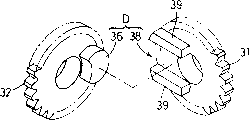
Above-mentioned crank-type variable-speed motion transmission mechanism D such as Fig. 3 and shown in Figure 5 constitute by cam ditch portion 38 and crank-pin 36, the former forms a pair of prominent bar 39,39 ground to be provided with along the cam ditch 38 of the radial direction of the 1st idler gear 31 on that side of facing with the 2nd idler gear 32 of the 1st idler gear 31; The latter is on that side of facing with the 1st idler gear 31 of the 2nd idler gear 32, the outstanding crank-pin 36 that is provided with that forms simultaneously when forming the 2nd idler gear 32.It is to be configured in and the 4th core X that constitutes the gyroaxis core of the 2nd idler gear 32 that crank-pin 36 is formed
4On the eccentric position and can enter 38 li in the cam ditch portion of the 1st idler gear 31 with being free to slide.Thus, driven by revolution and make the 1st idler gear 31 carry out the revolution operation that forms by revolution case 10 and center on the 3rd core X by the engagement of relative sun gear 23 when revolution case 10
3Carry out time rotational, crank-pin 36 passes to the 2nd idler gear 32 with this turning power, makes the 2nd idler gear 32 around the 4th core X
4And turn round.And by the 3rd core X
3With the 4th core X
4Off-centre makes the inside of crank-pin 36 in cam ditch portion 38, and the radial direction of edge the 1st idler gear 31 reciprocatingly slides, Yi Bian the turning power of transmission.Therefore, even crank-type variable-speed motion transmission mechanism D is the 1st idler gear 31 with the constant speed revolution, the 2nd idler gear 32 is also with the variable speed revolution, and the 1st idler gear 31 and the 2nd idler gear 32 are with as shown in Figure 9 phase relation M
1Interlock makes the 1st center tooth 31 and the interlock of the 2nd idler gear 32 variable speeds pivotally.
Because planetary gear 30 is round gyroaxis core X
1Carry out the rotating shaft core X on the rotating revolution case 10
2The upper edge with return the revolution of case 10 switched in opposite directions, thereby when observing the action of seedling-transplanting device from the outside, the result is that planetary gear 30 is swung rice transplanting pawl supported box 13 in the predetermined angular scope.Especially on this seedling-transplanting device, rotary motive power transmission mechanism S is set for revolution case 10 and planetary gear 30 relatively rotates in linkage by phase relation N shown in Figure 10.Thus, along with being turned round, revolution case 10 drives, make a pair of rice transplanting pawl supported box 13,13 be undertaken driving pivotally relatively by phase relation N Football 1 Li of Figure 10 with revolution case 10 separately, thus, the leading section of a pair of rice transplanting pawl supported box 13,13 rice transplanting pawl 12 is separately depicted roughly elliptical orbit T shown in Figure 8
1The rice transplanting campaign.The phase place of the so-called planetary gear 30 of Figure 10 is to be illustrated in to observe planetary gear 30 from the outside, promptly during rice transplanting supported box 13, observes what kind of action (with reference to Fig. 8).
As shown in Figure 4, rice shoot pushing piece 15 is fixed on the end of the cramp bar 15a that withdraws from from rice transplanting pawl supported box 13 along rice transplanting pawl 12.Above-mentioned rice shoot is released operating mechanism E such as Fig. 2 and shown in Figure 4, by the camshaft 16 that is arranged on rice transplanting pawl supported box 13 inside, day arm beam of steelyard 20, release spring 22, constitute to the outstanding connecting rod that the end connected 18 in outside etc. from the rice transplanting pawl supported box 13 of camshaft 16.Camshaft 16 can center on and above-mentioned the 2nd core X
2Same axis core free rotaring ground supporting and has the cam 17 that is integrally formed operation rice shoot pushing piece 15 on rice transplanting pawl supported box 13.They arm beam of steelyard 20 energy free rotaring ground supportings are on the fulcrum 20a of rice transplanting pawl supported box 13.One end of it arm beam of steelyard 20 is connected with above-mentioned cramp bar 15a by connecting rod 19, and the other end of day arm beam of steelyard 20 is provided with the cam follower lver 21 that acts on the above-mentioned cam 17.As the counter-force member day arm beam of steelyard 20 is swingingly suppressed to it by releasing spring 22, make cramp bar 15a rely on a side of giving prominence to slidably, and the cam follower lver 21 of the sky arm beam of steelyard 20 is pressed onto on the side face of above-mentioned cam 17 from rice transplanting pawl supported box 13.The camshaft 16 of the camshaft 16 of a connecting rod 18 and a side's rice transplanting pawl supported box 13 and the opposing party's rice transplanting pawl supported box 13 conjointly is installed with, even rice transplanting pawl supported box 13 is with respect to 10 revolutions of revolution case, connecting rod 8 makes camshaft 16 not turn round case 10 relatively and is supporting camshaft 16 pivotally.Thus, along with rice transplanting pawl 12 carries out the rice transplanting campaign, rice transplanting pawl supported box 13 and camshaft 16 just turn round.Thus, day arm beam of steelyard 20 since cam 17 to the push action of cam follower lver 21 and center on fulcrum 20a by the action of release spring 22 and swing, cramp bar 15a is reciprocatingly slided.Thus, rice shoot is released operating mechanism E along with rice transplanting pawl 12 carries out the rice transplanting campaign, turning power by revolution case 10 drives, make rice shoot pushing piece 15 shown in Fig. 4 double dot dash line, on the active position of the front of rice transplanting pawl 12, release action by the operating physical force that the elastic recovering force of releasing spring 22 forms, perhaps representing with solid line as Fig. 4, than above-mentioned active position more on the non-working position by the base end side of rice transplanting pawl 12, the operating physical force that forms by cam 17 action of retiring from office.
Therefore, when 10 revolutions of revolution case are driven, make each rice transplanting pawl supported box 13,13 center on the 1st core X because of the revolution of revolution case 10
1Ground revolves round the sun, and centers on the 2nd core X by the effect of rotary motive power transmission mechanism S
2Ground carries out rotation, and the leading section of rice transplanting pawl 12 is depicted roughly elliptical orbit T
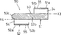
1, between the rice shoot conveying end of seedling carrying stand 4 and paddy field, make rice transplanting pawl 12 carry out the rice transplanting campaign up and down pivotally.Simultaneously, the rice shoot that is provided with rice transplanting pawl supported box 13 is released the turning power driving of operating mechanism E by revolution case 10, and the rice shoot pushing piece 15 and the rice transplanting campaign of rice transplanting pawl 12 are moved on non-working position and active position in linkage.Thus, block rice shoot and taking-up that the rice transplanting pawl 12 of the rice transplanting pawl 12 of a side rice transplanting pawl supported box 13 and the opposing party's rice transplanting pawl supported box 13 alternately is cut into 1 strain degree to bunch shape rice shoot that is placed on the seedling microscope carrier 4, descending is transported to the paddy field, is inserted into same delegation.And each rice transplanting pawl 12 is when the top of the seedling conveying end of seedling carrying stand 4 drops to the rice transplanting position, seedling pushing piece 15 is in non-working position, can carry out the seedling taking-up of rice transplanting pawl 12 and the maintenance of taking out seedling, when rice transplanting pawl 12 arrives the paddy field and carries out rice transplanting, seedling pushing piece 15 is in active position, and the seedling that rice transplanting pawl 12 is kept breaks away from ground with its release from rice transplanting pawl 12 easily.
Said gear fulcrum 50 as shown in Figure 6, is formed by such member, promptly respectively at one end side be provided with a core X
3The 1st axial region 51, at another distolateral core X that is provided with
4The 2nd axial region 52, between two axial regions 51,52, be provided with and connect that axial region 53 ground form.Connect axial region 53 and do not interfere with each other ground, have the also little external diameter of external diameter than the 1st axial region 51 and the 2nd axial region 52 with above-mentioned crank-pin 36, and the axle core X of two axial regions 51,52
3, X
4Depart under the state of the 1st axial region 51 and the 2nd axial region 52 and form with being connected.The end 51a with being connected axial region 53 opposition sides of the 1st axial region 51 inserts and to form on the connecting portion that the above-mentioned fulcrum pilot hole ground of splitting the axle 10b of branch of casing part 10A constitutes, and forms in the gear support portion of the end 51b of connection axial region 53 described examples of the 1st axial region 51 embedding formation outside above-mentioned the 1st idler gear 31 can be relatively freely to rotate.The end 52a with being connected axial region 53 opposition sides of the 2nd axial region inserts on the connecting portion that the above-mentioned fulcrum pilot hole ground of splitting the axle 10c of branch of casing part 10B constitutes to form, and the end 52b of connection axial region 53 sides of living in of the 2nd axial region 52 is that above-mentioned the 2nd idler gear 32 can form in the gear support portion of outer relatively freely to rotate embedding formation.That is, the 1st axial region 51 is as making the 1st idler gear 31 can center on the 3rd core X
3Free rotaring ground supporting makes the 2nd idler gear 32 can center on the 4th core X in 51, the 2 axial regions of above-mentioned the 1st axial region, 52 conducts of 10 li in revolution case
4Free rotaring ground supporting forms at above-mentioned the 2nd axial region 52 that turns round 10 li in case.Thus, the both end sides of the connecting portion 52a that constitutes of the connecting portion 51a that constitutes in end of gear fulcrum 50 and end by the 2nd axial region 52 by the 1st axial region 51 link to each other with revolution case 10 the ground connection both sides control the bearing state lower support the 1st and the 2nd idler gear 31,32.
As shown in Figure 7, above-mentioned the 1st axial region 51, the 2nd axial region 52 and be connected axial region 53 these 3 axial regions and form and divide other members.And connecting axial region 53 has connecting axle part 53a in both end sides, and the external diameter lining portion 53b bigger than two connecting axle part 53a, 53a arranged between two connecting axle part 53a, 53a.This connecting axle part 53a that connects a side of axial region 53 is inserted in the pilot hole 51c of the 1st axial region 51, and the opposing party's connecting axle part 53b is inserted in the pilot hole 52c of the 2nd axial region 52, assemble the 1st axial region 51, the 2nd axial region 52 thus and be connected axial region 53 these 3 axial regions.That is, gear fulcrum 50 is assembled each three members that form three axial regions 51,52,53 respectively and is constituted.Crank-pin 36 is set in the interval of the 1st axial region 51 and the 2nd axial region 52 to the 53b of lining portion and the 1st idler gear 31 does not interfere with each other, the interval that prominent bar 39 and the 2nd idler gear 32 do not interfere with each other.
On each fulcrum of the 1st fulcrum 51 and the 2nd fulcrum 52, be respectively equipped with the lightening hole 54 that connects along the total length of axial region 51,52, that be communicated with this lightening hole 54 and the 51b of gear support portion, 52b upper shed to oilhole 55.That is, it is alleviated by the weight reduction processing that remainder is eliminated.Also lightening hole 54 is stockpiled portion as lubricating oil, lubricating oil can be fed between the 1st axial region 51 and the 1st idler gear 31 from this lubricating oil portion of stockpiling, between the 2nd axial region 52 and the 2nd idler gear 32, between crank-pin 36 and the cam ditch portion 38.
The internal diameter that makes the internal diameter of lightening hole 54 and pilot hole 51c, 52c on the 1st axial region 51, the 2nd axial region 52 separately equally and make axle core from lightening hole 54 to axle core X
3, X
4The interval and from pilot hole 51c, 52c the axle core to axle core X
3, X
4The interval equally circumferentially form lightening hole 54 and pilot hole 51c, 52c abreast with 180 degree phase differences along axial region 51,52.That is, make the style of the style of lightening hole 54 and pilot hole identical.Like this, taking place on the pilot hole 51c under the occasion such as wearing and tearing, connection axial region 53 is changed from pilot hole 51c be inserted into 54 li of lightening holes, can transform gear fulcrum 50 into.
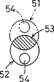
On above-mentioned connection axial region 53, as shown in Figure 6, be provided with from the outstanding shaft end 53c of the 2nd axial region 52 and end end faces the 1st axial region 51 opposition sides, recess 56 and the above-mentioned shaft end 53c that is located at the inside of the above-mentioned axle 10c of branch that splits casing part 10B by this shaft end 53c constitutes the detent mechanism 57 of the relative rigging position of the revolution case 10 of setting and gear fulcrum 50 with inserting.Promptly, by being assembled to, split on the casing part 10B two idler gears 31,32, make then two split casing part 10A, 10B the combination, when carrying out the assembling of rice transplanting mechanism 5, when being assembled to the 2nd axial region 52 of gear fulcrum 50 on the axle 10c of branch that splits casing 10B, make shaft end 53c enter recess 56 ground combinations.Like this, by shaft end 53c from the 4th core X
4Off-centre because shaft end 53c and recess 56 combinations, thereby is constrained to the 2nd axial region 52 and splits casing 10B relatively, because of the exchange of 56 of shaft end 53c and recess also angle rotary a little only, can too not turn round.And its inner face side of casing part 10B of splitting when assembling work forms posture up, and the revolution operating physical force that is caused by the gravity of these members acts on connecting axle 53 and the 2nd axial region 52 with regard to difficulty.And, connect axial region 53 round the axle core, with respect to the revolution of the 2nd axial region 52 by between the two frictional limited; The 2nd axial region 51 around the axle core of this assembly hole 51c with respect to the revolution that connects axial region 53 by between the two frictional limited.Therefore, detent mechanism 57 is by the combination of shaft end 53 and recess 56, set as described below whole gear fulcrum 50 with respect to whole revolution casing 10 at the circumferential assembling position of gear fulcrum.After promptly, setting for idler gear 31,32 is assembled into gear fulcrum 50 on the body portion 10B that unpacks, make this a pair of casing part 10A, 10B of splitting split the position relation ground combination of using bolt hole being connected of casing part 10A, 10B consistent with each other with two, the connecting portion 51a of the 1st axial region 51 of gear fulcrum 50 becomes assembling position as one man with the gear fulcrum assembly hole of the axle 10b of branch that splits casing 10A.
Below, the variation of explanation gear fulcrum.
Figure 11 represents to connect the variation that is connected axial region 53 of above-mentioned the 1st axial region 51 and the 2nd axial region 52.This connect axial region 53 by the coupling part 53a in the assembly hole 52c of assembly hole 51c that is inserted in the 1st axial region 51 and the 2nd axial region 52, constitute the pole member that shaft end 53c is arranged of above-mentioned detent mechanism 57, the barrel member that forms the above-mentioned lining 53b of portion that is embedded on this pole member outward constitutes.
Figure 12 represents the variation of gear fulcrum 50.This gear fulcrum 50 is the 1st axial region 51 and the 2nd axial region 52 and the 3rd axial region 53 all are shaped simultaneously as solid memder and make.Even in this case, the 1st axial region 51 yet has the 3rd core X
3, connecting portion 51a, the 51b of gear support portion, lightening hole 54 etc., the 2nd axial region 52 has the 4th core X
4, connecting portion 52a, the 52b of gear support portion, lightening hole 54, constitute the projection 53c of above-mentioned detent mechanism 57 etc.And shown in Figure 12 (b), the section configuration that connects axial region 53 becomes the 3rd core X from gear fulcrum 50
3With the 4th core X
4Shaft core direction see, with the shape of the 1st axial region 51 and the 2nd axial region 52 lap equal shape and size.
Figure 13 represents another variation of gear fulcrum 50.This gear fulcrum 50 is shown in Figure 13 (b) with difference shown in Figure 12, and the section configuration that connects axial region 53 is the 3rd core X from gear fulcrum 50
3With the 4th core X
4Shaft core direction see the shape that with the 1st fulcrum 51 and the 2nd axial region 52 lap similar shapes, become in the scope of not interfering crank-pin 36, size is bigger than this lap.
Figure 14 represents another variation of gear fulcrum 50.On this gear fulcrum 50, the length of the assembly hole 51c, the 52c that extend into the 1st axial region 51 and the 2nd axial region 52 that connects axial region 53 is shorter than the total length of an axial region 51,52.The projection 53a that constitutes detent mechanism 57 is arranged on the 2nd axial region 52.
Figure 15 represents another variation of gear fulcrum 50.On gear fulcrum 50, the member that will form a member that connects axial region 53 and the 1st axial region 51 and form the 2nd axial region forms respectively, by with these two members assembling formative gear fulcrums.Like this when making two members dividually, can adopt and make the method that forms the 2nd axial region 52 and is connected member and 51 1 members of the 1st axial region of formation of axial region 53 respectively.
Below, another embodiment as shown in figure 16 of rice transplanting mechanism 5 of the present invention is described.Only make rice transplanting pawl supported box 13 and revolution case 10 have the structure different with rice transplanting mechanism shown in Figure 2 among the crank-type variable-speed motion transmission mechanism D of revolution driving usefulness relatively, other structures all have the structure identical with rice transplanting mechanism shown in Figure 25.Therefore, here for fear of useless repetition, crank-type variable-speed motion transmission mechanism D only is described.
Promptly, this crank-type variable-speed motion transmission mechanism D is made of cam ditch portion 38 and crank-pin 36, the former be the 2nd idler gear 32 with the 1st idler gear 31 facing to the side on form that a pair of prominent bar 39,39 ground are provided with along the radial direction of the 2nd idler gear 32; The latter be the 1st idler gear 31 with the 2nd idler gear 32 facing to the side on, when forming the 1st idler gear 31, give prominence to setting by moulding.Crank-pin 36 is fitted over and the 3rd core X that constitutes the gyroaxis core of the 1st idler gear 32
3Eccentric position, and the cam ditch portion that can stretch at the 2nd idler gear 32 forms with being free to slide by 38 li.Thus, when revolution case 10 is driven by revolution, the revolution that the 1st idler gear 31 is formed by revolution case 10 centers on the 3rd core X with respect to the engagement of sun gear 32
3Carry out time rotational, crank-pin 36 passes to the 2nd gear 32 to this turning power, makes the 2nd gear 32 around the 4th core X
4And turn round.And by the 3rd core X
3With the 4th core X
4Off-centre, crank-pin 36 reciprocatingly slide along the radial direction of the 2nd idler gear 32 in the inside of cam ditch portion 38 and transmit revolution simultaneously.Therefore, crank-type variable-speed motion transmission mechanism D makes the 1st idler gear 31 and the interlock of the 2nd idler gear 32 variable speeds as described below, even i.e. the 1st idler gear 31 constant speed ground revolution, the also variable speed ground revolution of the 2nd idler gear 32, and the 1st idler gear 31 and the 2nd idler gear 32 are with phase relation M shown in Figure 180
2Turn round in linkage.
As said when Figure 10 is described, because planetary gear 30 is centering on an axle core X
1Carry out the gyroaxis core X on the rotating revolution case 10
2Upper edge and the revolution of revolution case 10 switched in opposite directions, thereby when observing the action of seedling-transplanting device from the outside, the result is that planetary gear 30 is swung rice transplanting pawl supported box 13 in the angular range of regulation.Especially at this seedling-transplanting device, set rotary motive power transmission mechanism S for revolution case 10 and planetary gear 30 by phase relation N shown in Figure 19
2Revolution relatively in linkage.Therefore, along with revolution case 10 is driven by revolution, make a pair of rice transplanting pawl supported box 13,13 respectively with the phase relation N of revolution case 10 by Figure 19
2Drive the rice transplanting campaign that makes the leading section of a pair of rice transplanting pawl supported box 13,13 rice transplanting pawl 12 separately retouch out substantially oblong-shaped track T2 shown in Figure 8 thus relatively pivotally.The phase place of the planetary gear 30 of so-called Figure 10 is expressions when observing planetary gear 30 from the outside and being rice transplanting pawl supported box 13, sees what kind of action (with reference to Figure 17).
Also can projection is set in revolution on the case 10 and the recess that this projection inserts is set on the gear fulcrum and the structure that constitutes as detent mechanism 57.
Can adopt also that have can free rotating roller and combine with cam ditch portion 38 by this roller, under the little situation of frictional resistance, transmit the pin of the band roller of turning power ground formation and realize crank-pin 36.
Claims (8)
1. rice transplanting mechanism, it is round the 1st core (X
1) can revolution case (10) with respect to rice transplanting transmission case (3) free rotaring ground supporting on, by fulcrum the rice transplanting pawl supporting mass (13) that rice transplanting pawl (12) is installed is supported to and can centers on and the 1st core (X
1) the 2nd parallel core (X
2) revolution relatively freely, have with rice transplanting pawl supporting mass (13) be integral rotating bolster (14) go up fixing planetary gear (30), can not be fixed on sun gear (23) on the rice transplanting transmission case (3) pivotally, with the 1st idler gear (31) of sun gear (23) engagement, round with the gyroaxis core (X of the 1st idler gear (31)
3) eccentric gyroaxis core (X
4) by revolution and with the 2nd idler gear (32) of planetary gear (30) engagement, make the variable-speed motion transmission mechanism (D) of the eccentric mechanism formula that the 1st idler gear (31) and the 2nd idler gear (32) variable speed link; Be provided with revolution, the leading section of rice transplanting pawl (12) depicted roughly be elliptical orbit to make the relative rotary motive power transmission mechanism (S) that turns round driving of rice transplanting pawl supporting mass (13) (T1) with revolution case (10) along with revolution case (10); It is characterized in that: gear fulcrum (50) is provided with an end bearing went up and supporting with the other end the 1st idler gear (31) at revolution case (10) the 1st axial region (51); One end bearing goes up and is supporting with the other end the 2nd axial region (52) of the 2nd idler gear (32) at revolution case (10); The connection axial region (53) that the 1st axial region (51) and the 2nd axial region (52) are connected prejudicially; The 1st idler gear (31) and the 2nd idler gear (32) are supported on the revolution case (10) by said gear fulcrum (50).
2. rice transplanting mechanism as claimed in claim 1 is characterized in that: said gear fulcrum (50) is divided into and is assembled into after following two members form respectively; These two members are respectively to prop up the member that axial region (52) forms by the axial region (51) of the side in above-mentioned the 1st axial region (51) and the 2nd axial region (52) with the above-mentioned member that is connected that axial region (53) forms and by the opposing party.
3. rice transplanting mechanism as claimed in claim 1 is characterized in that: said gear fulcrum (50) is by independent 3 members making respectively, promptly by above-mentioned the 1st axial region (51) and the 2nd axial region (52) be connected axial region (53) and assemble.
4. rice transplanting mechanism as claimed in claim 1 is characterized in that: by with above-mentioned the 1st axial region (51) and the 2nd axial region (52) be connected these 3 axial regions of axial region (53) and be integral the ground moulding and be made into said gear fulcrum (50).
5. rice transplanting mechanism as claimed in claim 1, it is characterized in that: it is provided with detent mechanism (57), here the teat (53c) by making the end that is positioned at said gear fulcrum (50) and the side among the above-mentioned revolution case (10) and combining of the recess that is positioned at the opposing party (56) set gear fulcrum (50) with respect to revolution case (10) at the assembling position that makes progress in gear fulcrum week.
6. rice transplanting mechanism as claimed in claim 1 is characterized in that: said gear fulcrum (50) is provided with the lightening hole (54) that is positioned on above-mentioned the 1st axial region (51) and the 2nd axial region (52).
7. as any one described rice transplanting mechanism among the claim 1-6, it is characterized in that: above-mentioned crank-type variable-speed motion transmission mechanism (D) is by being located at the cam ditch portion (38) on above-mentioned the 1st idler gear (31) and can going up, make the gyroaxis core (X of itself and this 2nd idler gear (32) with this cam ditch portion (38) in combination at above-mentioned the 2nd idler gear (32)
4) crank-pin (36) that is provided with prejudicially constitutes.
8. seedling-transplanting device as claimed in claim 7 is characterized in that: the gyroaxis core (X of above-mentioned the 2nd idler gear (32)
4) be provided in gyroaxis core (X than above-mentioned the 1st idler gear (31)
3) the gyroaxis core (X of more approaching above-mentioned revolution case (10)
1) on one side.
Applications Claiming Priority (6)
| Application Number | Priority Date | Filing Date | Title |
|---|---|---|---|
| JP42819/1996 | 1996-02-29 | ||
| JP42819/96 | 1996-02-29 | ||
| JP42820/1996 | 1996-02-29 | ||
| JP04282096A JP3377357B2 (en) | 1996-02-29 | 1996-02-29 | Seedling planting mechanism |
| JP42820/96 | 1996-02-29 | ||
| JP04281996A JP3294098B2 (en) | 1996-02-29 | 1996-02-29 | Seedling planting mechanism |
Publications (2)
| Publication Number | Publication Date |
|---|---|
| CN1158212A CN1158212A (en) | 1997-09-03 |
| CN1069154C true CN1069154C (en) | 2001-08-08 |
Family
ID=26382559
Family Applications (1)
| Application Number | Title | Priority Date | Filing Date |
|---|---|---|---|
| CN96101497A Expired - Lifetime CN1069154C (en) | 1996-02-29 | 1996-06-08 | Rice transplanting mechanism |
Country Status (2)
| Country | Link |
|---|---|
| KR (1) | KR100193457B1 (en) |
| CN (1) | CN1069154C (en) |
Families Citing this family (1)
| Publication number | Priority date | Publication date | Assignee | Title |
|---|---|---|---|---|
| CN101933424B (en) * | 2010-09-03 | 2013-04-17 | 江苏大学 | Differential eccentric gear train transplanting mechanism |
Citations (5)
| Publication number | Priority date | Publication date | Assignee | Title |
|---|---|---|---|---|
| JPS4917805A (en) * | 1972-04-12 | 1974-02-16 | ||
| CN87103763A (en) * | 1986-09-17 | 1988-03-30 | 井关农机株式会社 | rice transplanter |
| JPH03143315A (en) * | 1990-09-18 | 1991-06-18 | Yanmar Agricult Equip Co Ltd | Forced seedling transplantation apparatus of transplantation machine |
| JPH04179403A (en) * | 1990-11-13 | 1992-06-26 | Iseki & Co Ltd | Seedling planting apparatus of transplantation machine |
| JP3143315B2 (en) * | 1994-03-29 | 2001-03-07 | 株式会社日立ホームテック | Cooking device |
-
1996
- 1996-05-22 KR KR1019960017419A patent/KR100193457B1/en not_active IP Right Cessation
- 1996-06-08 CN CN96101497A patent/CN1069154C/en not_active Expired - Lifetime
Patent Citations (5)
| Publication number | Priority date | Publication date | Assignee | Title |
|---|---|---|---|---|
| JPS4917805A (en) * | 1972-04-12 | 1974-02-16 | ||
| CN87103763A (en) * | 1986-09-17 | 1988-03-30 | 井关农机株式会社 | rice transplanter |
| JPH03143315A (en) * | 1990-09-18 | 1991-06-18 | Yanmar Agricult Equip Co Ltd | Forced seedling transplantation apparatus of transplantation machine |
| JPH04179403A (en) * | 1990-11-13 | 1992-06-26 | Iseki & Co Ltd | Seedling planting apparatus of transplantation machine |
| JP3143315B2 (en) * | 1994-03-29 | 2001-03-07 | 株式会社日立ホームテック | Cooking device |
Also Published As
| Publication number | Publication date |
|---|---|
| CN1158212A (en) | 1997-09-03 |
| KR970061048A (en) | 1997-09-12 |
| KR100193457B1 (en) | 1999-06-15 |
Similar Documents
| Publication | Publication Date | Title |
|---|---|---|
| KR100740958B1 (en) | Power transmission system | |
| CN101855475B (en) | A transmission system for power generation | |
| EP0067867A1 (en) | Infinitely variable gear ratio transmission. | |
| CN1069154C (en) | Rice transplanting mechanism | |
| CN1831372A (en) | Hypocycloid pinwheel planetary gearing | |
| CN200985985Y (en) | Multiple angle cranks, low vibrating and few teeth difference speed reducer | |
| CN1320733C (en) | Roller with electric motor in it | |
| CN1334905A (en) | Continuously variable transmission | |
| CN1443953A (en) | Angle transfer lrror reducing method for swinging inner-connected meshed planetary gear equipment and swinging inner-connected planet-gear speed changer | |
| CN1046023A (en) | Extrinsic useless oscillation motions is converted to the device of useful torque | |
| CN1576645A (en) | Speed reducer | |
| CN1582371A (en) | Transmission unit provided with swash plate (variants) and differential speed converter (variants) based thereof | |
| CN1014923B (en) | Bent lever cycloidal toothed gearing | |
| US20060240936A1 (en) | Self-regulating continuosly variable transmission | |
| CN101046239A (en) | Retarder | |
| CN2303126Y (en) | High efficiency rocking type active teeth speed reducer | |
| JPS61252935A (en) | Reduction gear for driving device of crawler vehicles | |
| CN109780142A (en) | A kind of active-tooth transmission | |
| CN206000942U (en) | Elasticity conversion decelerator | |
| CN1067840C (en) | Seedling-planting device | |
| CN105090444B (en) | Buncher | |
| JP5049070B2 (en) | Seedling planting equipment in rice transplanter | |
| CN2747417Y (en) | Composite rolling active tooth driving device for double-phase cam shock wave | |
| US557676A (en) | Propelling mechanism for bicycles | |
| US10156287B2 (en) | Crank-less motion converter |
Legal Events
| Date | Code | Title | Description |
|---|---|---|---|
| C10 | Entry into substantive examination | ||
| SE01 | Entry into force of request for substantive examination | ||
| C06 | Publication | ||
| PB01 | Publication | ||
| C14 | Grant of patent or utility model | ||
| GR01 | Patent grant | ||
| CX01 | Expiry of patent term |
Granted publication date: 20010808 |
|
| EXPY | Termination of patent right or utility model |