CN106908033B - Synchronous measuring device and method for multipoint displacement of top plate of goaf - Google Patents
Synchronous measuring device and method for multipoint displacement of top plate of goaf Download PDFInfo
- Publication number
- CN106908033B CN106908033B CN201710232068.6A CN201710232068A CN106908033B CN 106908033 B CN106908033 B CN 106908033B CN 201710232068 A CN201710232068 A CN 201710232068A CN 106908033 B CN106908033 B CN 106908033B
- Authority
- CN
- China
- Prior art keywords
- displacement
- grating
- goaf
- inner cylinder
- roof
- Prior art date
- Legal status (The legal status is an assumption and is not a legal conclusion. Google has not performed a legal analysis and makes no representation as to the accuracy of the status listed.)
- Active
Links
Images


Classifications
-
- G—PHYSICS
- G01—MEASURING; TESTING
- G01C—MEASURING DISTANCES, LEVELS OR BEARINGS; SURVEYING; NAVIGATION; GYROSCOPIC INSTRUMENTS; PHOTOGRAMMETRY OR VIDEOGRAMMETRY
- G01C5/00—Measuring height; Measuring distances transverse to line of sight; Levelling between separated points; Surveyors' levels
-
- G—PHYSICS
- G01—MEASURING; TESTING
- G01B—MEASURING LENGTH, THICKNESS OR SIMILAR LINEAR DIMENSIONS; MEASURING ANGLES; MEASURING AREAS; MEASURING IRREGULARITIES OF SURFACES OR CONTOURS
- G01B11/00—Measuring arrangements characterised by the use of optical techniques
- G01B11/02—Measuring arrangements characterised by the use of optical techniques for measuring length, width or thickness
Landscapes
- Physics & Mathematics (AREA)
- General Physics & Mathematics (AREA)
- Engineering & Computer Science (AREA)
- Radar, Positioning & Navigation (AREA)
- Remote Sensing (AREA)
- Testing Or Calibration Of Command Recording Devices (AREA)
Abstract
本发明公开了一种采空区顶板多点位移同步测量装置及其测量方法,包括壳体、锚爪、钢丝绳、检测顶板沉降的光栅尺位移传感器、若干检测覆岩深部位移的光栅尺位移传感器,无线通信模块和回弹装置;所述检测顶板沉降的光栅尺位移传感器的光栅发射头和标尺光栅分别固定于内筒外壁和保护筒内壁;所述检测覆岩深部位移的光栅尺位移传感器的光栅发射头连接钢丝绳,标尺光栅固定于内筒内壁;所述位移传感器通过无线通信模块向接收主机输出信号。本发明利用采空区顶板各基点的位移变化同时准确计算顶板表面沉降量和覆岩深部位移,并通过无线传输网络和以太网实现数据传输,无需采空区的复杂环境中埋设传输线路。
The invention discloses a multi-point displacement synchronous measuring device for the roof of a goaf and a measuring method thereof, comprising a shell, an anchor claw, a steel wire rope, a grating ruler displacement sensor for detecting the settlement of the roof, and several grating ruler displacement sensors for detecting the displacement of the deep part of the overlying rock. , wireless communication module and rebound device; the grating transmitter head and the scale grating of the grating scale displacement sensor for detecting roof settlement are respectively fixed on the outer wall of the inner cylinder and the inner wall of the protection cylinder; the grating scale displacement sensor for detecting the deep displacement of the overburden The grating transmitting head is connected with the steel wire rope, and the scale grating is fixed on the inner wall of the inner cylinder; the displacement sensor outputs a signal to the receiving host through the wireless communication module. The invention utilizes the displacement change of each base point of the roof of the goaf to accurately calculate the surface settlement of the roof and the deep displacement of the overlying rock at the same time, and realizes data transmission through a wireless transmission network and Ethernet, without burying transmission lines in the complex environment of the goaf.
Description
技术领域technical field
本发明涉及煤矿采空区顶板稳定性监测领域,尤其涉及一种充填开采采空区顶板沉降及覆岩深部位移同步测量装置及测量方法。The invention relates to the field of roof stability monitoring in goafs of coal mines, in particular to a synchronous measurement device and measurement method for roof settlement and displacement of overlying rock in backfilling and mining goafs.
背景技术Background technique
在煤层开采过程中,由于应力释放或其他采动影响,采空区顶板会产生移动及塌冒,影响安全生产和地层(表)环境;为了防止顶板产生移动及塌冒,目前的办法是,在形成的采空区内用充填体及时充填,达到支撑顶板、减小顶板的垮落和变形、减轻工作面压力、减少覆岩的变形和破坏程度的目的。对采空区顶板和覆岩的运动规律的研究,是充填开采技术发展的关键。In the process of coal seam mining, due to stress release or other mining influences, the roof of the goaf will move and collapse, affecting safe production and the formation (surface) environment; in order to prevent the roof from moving and collapsing, the current method is: In the formed goaf, the filling body is used to fill in time, so as to support the roof, reduce the collapse and deformation of the roof, reduce the pressure of the working face, and reduce the deformation and damage of the overlying rock. The study of the movement law of the roof and the overlying rock in the goaf is the key to the development of the backfill mining technology.
目前研究采空区顶板和覆岩的运动规律,需通过现场监测的方法来评价。其中顶板表面位移和覆岩深部位移是两项重要指标。At present, the movement law of the roof and overlying rock in the goaf needs to be evaluated by on-site monitoring. Among them, the displacement of the roof surface and the deep displacement of the overlying rock are two important indicators.
采空区顶板沉降量通常采用顶底板间安装套筒式监测装置测量。如中国专利公开号CN204286286U公开了一种充填体位移监测装置,其工作原理是:固定于采空区顶板的内筒通过尺带与固定于外筒中的检测总成连接,通过尺带的伸缩测得顶板沉降量。该装置仅可测得采空区顶板表面沉降量,并不具备测量覆岩深部位移的功能,测量数据无法全面反映上覆岩层运动规律;同时,该装置需要在充填采空区埋设传输线路,埋设过程复杂且给施工人员带来了安全隐患。The roof settlement of the goaf is usually measured by installing a sleeve-type monitoring device between the roof and floor. For example, Chinese Patent Publication No. CN204286286U discloses a filling body displacement monitoring device. Its working principle is as follows: the inner cylinder fixed on the roof of the goaf is connected with the detection assembly fixed in the outer cylinder through a ruler, and the measuring assembly is measured by the extension of the ruler. The roof settlement is obtained. The device can only measure the subsidence of the roof surface of the goaf, and does not have the function of measuring the deep displacement of the overlying rock, and the measurement data cannot fully reflect the movement law of the overlying rock. The burying process is complicated and brings safety hazards to the construction workers.
中国专利公开号CN203224223U公开了一种基于位移传感器与无线传输的检测围岩离层的装置,其工作原理是:将锚固头固定于不同深度的岩层中,当围岩产生离层时,锚固头相对装置移动产生位移带动位移传感器移动,并通过无线通信模块实时传输到接收主机。该装置安装于顶板表面,由于没有底板基点,无法测得顶板表面沉降量,仅可测得岩层间相对位移,即离层距离。Chinese Patent Publication No. CN203224223U discloses a device for detecting the separation of surrounding rocks based on displacement sensors and wireless transmission. The displacement generated by the movement of the relative device drives the displacement sensor to move, and is transmitted to the receiving host in real time through the wireless communication module. The device is installed on the surface of the roof. Since there is no base point of the bottom plate, the settlement of the roof surface cannot be measured, and only the relative displacement between the rock layers, that is, the distance from the layer, can be measured.
上述两个文献记载的测量技术均只有单一功能,目前尚不存在一种可以同步测量采空区顶板表面沉降和覆岩深部位移的装置及使用方法。The measurement technologies described in the above two documents have only a single function, and there is currently no device and method for synchronously measuring the surface settlement of the goaf roof surface and the displacement of the overlying rock.
发明内容SUMMARY OF THE INVENTION
为了解决上述现有技术中存在的问题,本发明提供了一种采空区顶板多点位移同步测量装置,本装置采用光栅尺高精度位移传感器实现测量功能,不但可同时测量采空区顶板表面位移和覆岩深部多点位移,而且操作方便,数据准确可靠,监测数据通过无线传输,无需采空区埋设线路的复杂过程,避免了长距离传输线路易破坏和施工人员的安全隐患问题。In order to solve the above-mentioned problems in the prior art, the present invention provides a multi-point displacement synchronous measuring device for the roof of the goaf. Displacement and multi-point displacement in the deep part of the overlying rock are easy to operate, and the data is accurate and reliable. The monitoring data is transmitted wirelessly, without the complicated process of burying the line in the goaf, avoiding the problem of easy damage to the long-distance transmission line and hidden safety hazards of construction personnel.
本发明同时提供利用这种装置对采空区顶板表面位移和覆岩深部位移进行同步测量的方法。The invention also provides a method for synchronously measuring the displacement of the roof surface of the goaf and the deep displacement of the overlying rock by using the device.
为了实现上述目的,本发明采用的技术方案是:In order to achieve the above object, the technical scheme adopted in the present invention is:
一种采空区顶板多点位移同步测量装置,其特征在于,它由采空区顶板沉降测量部分、多套覆岩深部位移测量部分和壳体组成。The utility model relates to a multi-point displacement synchronous measuring device for the roof of a goaf, which is characterized in that it is composed of a roof settlement measuring part of the goaf, multiple sets of deep displacement measuring parts of the overlying rock and a shell.
所述的壳体是一个筒状结构,主要包括用于随采空区顶板沉降移动的内筒和用于保护和支撑内筒的保护筒,保护筒底部固定在底座上,保护筒腔内底部安置有平衡弹簧,平衡弹簧顶部顶在内筒底部,内筒顶部设有端盖,要求平衡弹簧一直处于压缩状态,使内筒始终与顶板接触,随顶板在保护筒内发生同步移动;内筒和保护筒间设有密封圈。The casing is a cylindrical structure, which mainly includes an inner cylinder for moving with the settlement of the roof of the goaf and a protection cylinder for protecting and supporting the inner cylinder. The bottom of the protection cylinder is fixed on the base to protect the bottom of the cylinder cavity. A balance spring is installed, the top of the balance spring is on the bottom of the inner cylinder, and the top of the inner cylinder is provided with an end cover. A sealing ring is arranged between the protective cylinder.
所述的顶板沉降量测量部分,是在保护筒腔内壁固定有第一光栅尺位移传感器,第一光栅尺位移传感器用于检测采空区顶板沉降位移;第一光栅尺位移传感器的光栅读数头固定于处在保护筒腔内的那段内筒外壁,第一光栅尺位移传感器的标尺光栅固定于保护筒内壁;第一光栅尺位移传感器底端连接有第一无线通信模块,第一无线通信模块将第一光栅尺位移传感器信号转换为数字量并传输至接收主机;In the roof settlement measurement part, a first grating scale displacement sensor is fixed on the inner wall of the protective cylinder cavity, and the first grating scale displacement sensor is used to detect the roof settlement displacement of the goaf; the grating reading head of the first grating scale displacement sensor It is fixed on the outer wall of the inner cylinder in the protective cylinder cavity, and the scale grating of the first grating scale displacement sensor is fixed on the inner wall of the protective cylinder; the bottom end of the first grating scale displacement sensor is connected with a first wireless communication module, the first wireless communication module The module converts the signal of the first grating scale displacement sensor into a digital quantity and transmits it to the receiving host;
所述的覆岩深部位移量测量部分,是在内筒腔内壁固定有第二光栅尺位移传感器,第二光栅尺位移传感器用于检测覆岩深部位移;第二光栅尺位移传感器的光栅读数头与钢丝绳连接固定,第二光栅尺位移传感器的标尺光栅固定于内筒内壁,随内筒移动与光栅读数头发生相对移动;第二光栅尺位移传感器底端连接有第二无线通信模块;在内筒内壁上固定有钢丝绳回弹装置,回弹装置处于第二无线通信模块下方,回弹装置的钢丝绳向上拉出自由穿过内筒端盖后再连接一个用于确定测量基点的锚爪。The said part for measuring the displacement of the deep part of the overlying rock is that a second grating scale displacement sensor is fixed on the inner wall of the inner cylinder cavity, and the second grating scale displacement sensor is used to detect the displacement of the deep part of the overlying rock; the grating reading head of the second grating scale displacement sensor It is connected and fixed with the steel wire rope, and the scale grating of the second grating scale displacement sensor is fixed on the inner wall of the inner cylinder, and moves relative to the grating reading head with the movement of the inner cylinder; the bottom end of the second grating scale displacement sensor is connected with a second wireless communication module; A steel wire rope rebound device is fixed on the inner wall of the cylinder, and the rebound device is located below the second wireless communication module.
进一步地,第一和第二无线通信模块将传感器的电信号分析转化为数字量,通过无线传输的方式发送至接收主机。Further, the first and second wireless communication modules analyze the electrical signal of the sensor and convert it into a digital quantity, which is sent to the receiving host by means of wireless transmission.
进一步地,接收主机将收到的数据处理后通过以太网传输的方式传输到接收终端。Further, the receiving host processes the received data and transmits it to the receiving terminal by means of Ethernet transmission.
进一步地,内筒与顶盖通过紧固螺钉连接。Further, the inner cylinder and the top cover are connected by fastening screws.
进一步地,回弹装置通过紧固螺钉固定于内筒腔内。Further, the rebound device is fixed in the inner cylinder cavity by tightening screws.
为了保证弹簧在常时保持压缩状态,在保护筒壁上设有定位螺钉,定位螺钉穿透保护筒壁顶在内筒外壁。In order to ensure that the spring is always kept in a compressed state, a positioning screw is arranged on the wall of the protection cylinder, and the positioning screw penetrates the wall of the protection cylinder and tops the outer wall of the inner cylinder.
利用上述装置实现顶板沉降量和覆岩位移量同步测量的方法,具体步骤如下:Utilize the above-mentioned device to realize the method for simultaneous measurement of roof settlement and overlying rock displacement, and the specific steps are as follows:
第一步:钻取钻孔Step 1: Drill the hole
采空区充填之前,在待测点顶板钻取垂直钻孔,孔深根据覆岩情况及监测要求确定;Before the goaf is filled, a vertical hole is drilled on the roof of the point to be measured, and the hole depth is determined according to the overlying rock conditions and monitoring requirements;
第二步:安装装置Step 2: Install the device
在采空区待监测区清理出约1m2的作业空间,将采空区顶板多点位移同步测量装置放置于待测区底板,拉出所有覆岩深部位移量测量部分的钢丝绳,将钢丝绳的锚爪一一伸入钻孔,固定于钻孔内部各个测点;Clear a working space of about 1m 2 in the area to be monitored in the goaf, place the multi-point displacement synchronous measuring device on the roof of the goaf on the bottom plate of the area to be measured, pull out all the steel wire ropes of the deep displacement measurement part of the overlying rock, and connect the The anchor claws extend into the borehole one by one and are fixed at each measuring point inside the borehole;
第三步:固定装置Step 3: Fixing the Device
松开定位螺钉,提升内筒,使内筒端盖与采空区顶板接触,然后将底座通过锚栓固定于采空区底板上;Loosen the positioning screw, lift the inner cylinder, make the end cover of the inner cylinder contact the roof of the goaf, and then fix the base on the floor of the goaf through anchor bolts;
第四步:确定顶板沉降量和覆岩位移量Step 4: Determine the roof settlement and overlying rock displacement
设初始状态下检测顶板表面沉降的第一光栅尺位移传感器读数为l0,连接有锚爪的多个第二光栅尺位移传感器读数分别为l1,l2,…ln,测量后的第一光栅尺位移传感器读数为l0',多个第二光栅尺位移传感器读数分别为l1',l2',…ln',则第j个锚爪和第k个锚爪固定点间的覆岩离层距离hjk=|(lj'-lj)-(lk'-lk)|,顶板至第j个锚爪固定点间的覆岩位移量为hj0=(lj'-lj)-(l0'-l0),顶板沉降量L=l0'-l0。In the initial state, the reading of the displacement sensor of the first grating ruler that detects the settlement of the roof surface is l 0 , and the readings of the displacement sensors of the second grating ruler connected with the anchor claw are l 1 , l 2 ,...l n respectively. The readings of the displacement sensors of one grating scale are l 0 ', and the readings of the displacement sensors of a plurality of second grating scales are l 1 ', l 2 ',...l n ' respectively, then the distance between the jth anchor claw and the kth anchor claw fixing point The overlying rock separation distance h jk =|(l j '-l j )-(l k '-l k )|, the overlying rock displacement from the roof to the j-th anchor claw fixing point is h j0 =(l j '-l j )-(l 0 '-l 0 ), the roof settlement L=l 0 '-l 0 .
上述n代表第二光栅尺位移传感器的个数,j、k代表其中两个传感器对应的两个锚爪。The above n represents the number of the second grating scale displacement sensors, and j and k represent the two anchor claws corresponding to the two sensors.
下面根据本发明的监测原理说明其积极效果The positive effects of the present invention will be explained below according to the monitoring principle of the present invention.
1、本发明在测顶板沉降时,内筒和保护筒发生相对错动,也就是分别固定在两个筒壁上的第一光栅尺位移传感器光栅读数头和标尺光栅发生错动,错动的距离就是顶板沉降的位移。在顶板下沉过程中,钢丝绳始终处于拉紧状态,如果锚爪的固定点和顶板之间的岩体同时下沉没有发生离层,钢丝绳长度不变;如果锚爪固定点和顶板之间的岩体发生离层,钢丝绳长度被拉长,由于第二光栅尺位移传感器的光栅尺读数头固定在钢丝绳上,标尺光栅固定在内筒内壁,钢丝绳和内筒的相对错动距离反映覆岩位移。从而实现将顶板沉降量和覆岩位移量两种数据由一台装置同步测量,测得的同步数据对采空区覆岩运动规律有更清晰全面的认知。1. When measuring the settlement of the top plate of the present invention, the inner cylinder and the protective cylinder are displaced relative to each other, that is, the first grating displacement sensor grating reading head and the scale grating, which are respectively fixed on the two cylinder walls, are dislocated. The distance is the displacement of the roof settlement. During the subsidence of the roof, the wire rope is always in a state of tension. If the rock mass between the anchor claw and the roof sinks at the same time without separation, the length of the wire rope will remain unchanged; When the rock mass separates from the layer, the length of the wire rope is elongated. Since the scale reading head of the second scale displacement sensor is fixed on the wire rope, and the scale grating is fixed on the inner wall of the inner cylinder, the relative dislocation distance between the wire rope and the inner cylinder reflects the overlying rock displacement. . In this way, two kinds of data of roof settlement and overlying rock displacement can be synchronously measured by one device, and the measured synchronous data can have a clearer and more comprehensive understanding of the movement law of overlying rock in the goaf.
2、本发明的监测数据通过无线及以太网的方式传输,无需在采空区埋设线路的复杂过程,同时避免了长距离传输线路易破坏的问题。监测装置工作可靠,使用寿命得到有效延长。2. The monitoring data of the present invention is transmitted by wireless and Ethernet, without the complicated process of burying lines in the goaf, and at the same time avoiding the problem of easy damage of long-distance transmission lines. The monitoring device works reliably, and the service life is effectively extended.
3、本发明的位移测量采用光栅尺高精度位移传感器,数据准确可靠。3. The displacement measurement of the present invention adopts a grating ruler high-precision displacement sensor, and the data is accurate and reliable.
附图说明Description of drawings
为了更清楚地说明本发明实施例或现有技术中的技术方案,下面将对实施例或现有技术描述中所需要使用的附图作简单的介绍,显而易见地,下面描述中的附图仅仅是本发明的一些实施例,对于本领域普通技术人员来讲,在不付出创造性劳动的前提下,还可以根据这些附图获得其他的附图。In order to more clearly illustrate the embodiments of the present invention or the technical solutions in the prior art, the following briefly introduces the accompanying drawings used in the description of the embodiments or the prior art. Obviously, the drawings in the following description are only These are some embodiments of the present invention. For those of ordinary skill in the art, other drawings can also be obtained according to these drawings without creative efforts.
图1为本发明实施例的整体结构示意图,图中以内筒中设一套覆岩深部位移测量部分为例;1 is a schematic diagram of the overall structure of an embodiment of the present invention, in which a set of deep displacement measurement parts of the overlying rock is provided in the inner cylinder as an example;
图2为本发明的监测网络示意图;Fig. 2 is the monitoring network schematic diagram of the present invention;
图3为本发明的光栅尺位移传感器结构示意图,图中以第二光栅尺位移传感器的布置方式为例。FIG. 3 is a schematic structural diagram of the grating scale displacement sensor of the present invention, in which the arrangement of the second grating scale displacement sensor is taken as an example.
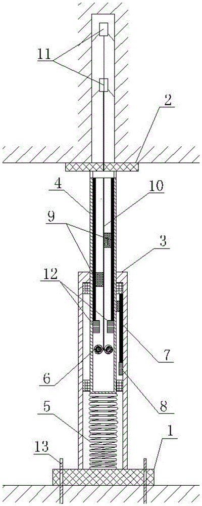
图中:1-底座;2-端盖;3-保护筒;4-内筒;5-平衡弹簧;6-钢丝绳回弹装置;7-第一光栅尺位移传感器;8-第一无线通信模块;9-第二光栅尺位移传感器;10-钢丝绳;11-锚爪;12-第二无线通信模块;13-锚栓;14-接收主机;15-接收终端;16-第二光栅尺位移传感器的标尺光栅;17-第二光栅尺位移传感器的光栅读数头。In the figure: 1-base; 2-end cover; 3-protection cylinder; 4-inner cylinder; 5-balance spring; 6-wire rope rebound device; 7-first grating scale displacement sensor; 8-first wireless communication module ; 9- the second grating ruler displacement sensor; 10- steel wire rope; 11- anchor claw; 12- the second wireless communication module; 13- anchor bolt; 14- receiving host; 15- receiving terminal; 16- the second grating ruler displacement sensor The scale grating; 17- the grating reading head of the second grating scale displacement sensor.
具体实施方式Detailed ways
下面将结合本发明实施例中的附图,对本发明实施例中的技术方案进行清楚、完整的描述。The technical solutions in the embodiments of the present invention will be clearly and completely described below with reference to the accompanying drawings in the embodiments of the present invention.
如图1、2所示的一种采空区顶板多点位移同步测量装置,由采空区顶板沉降测量部分、一套覆岩深部位移测量部分和壳体组成。As shown in Figures 1 and 2, a multi-point displacement synchronous measurement device for the roof of the goaf is composed of a roof settlement measurement part of the goaf, a set of deep displacement measurement parts of the overlying rock and a shell.
所述的壳体是一个筒状结构,包括内筒4和保护筒3,内筒4用于随采空区顶板沉降移动,保护筒3用于保护和支撑内筒4;保护筒3底部固定在底座1上,使用时底座1通过锚栓14固定于底板上,保护筒3腔内底部安置有平衡弹簧5,平衡弹簧5顶部顶在内筒4底部,内筒4顶部通过紧固螺钉设有端盖2,要求平衡弹簧5一直处于压缩状态,使用时,内筒4的端盖2始终与顶板接触,随顶板在保护筒3内发生同步移动;内筒4和保护筒3间设有密封圈。在保护筒3壁上设有定位螺钉(图中未画出),定位螺钉穿透保护筒3壁顶在内筒4外壁。The casing is a cylindrical structure, including an
所述的顶板沉降量测量部分,是在保护筒3筒腔内壁固定有第一光栅尺位移传感器7,第一光栅尺位移传感器7用于检测采空区顶板沉降位移;第一光栅尺位移传感器7的光栅读数头固定于处在保护筒3腔内的那段内筒4外壁,第一光栅尺位移传感器7的标尺光栅固定于保护筒3内壁;第一光栅尺位移传感器7底端连接有第一无线通信模块8,第一无线通信模块8将第一光栅尺位移传感器7电信号转换为数字量并通过无线传输的方式传输至接收主机14;接收主机14将收到的数据处理后通过以太网传输的方式传输到接收终端15。The roof settlement measurement part is that a first grating
所述的覆岩深部位移量测量部分,是在内筒4腔内壁固定有第二光栅尺位移传感器9,第二光栅尺位移传感器9用于检测覆岩深部位移;第二光栅尺位移传感器9的光栅读数头与钢丝绳10连接固定,第二光栅尺位移传感器9的标尺光栅固定于内筒4内壁,随内筒4移动与光栅读数头发生相对移动;第二光栅尺位移传感器9底端连接有第二无线通信模块12;在内筒4内壁上通过紧固螺钉固定有钢丝绳回弹装置6,钢丝绳回弹装置6处于第二无线通信模块12下方,第二无线通信模块12将第二光栅尺位移传感器9的电信号分析转化为数字量,通过无线传输的方式发送至接收主机14,接收主机14将收到的数据处理后通过以太网传输的方式传输到接收终端15;在端盖2上设有出线孔,将回弹装置6的钢丝绳10向上抽出自由穿过出线孔后再连接一个用于确定测量基点的锚爪11。In the described part for measuring the displacement of the deep part of the overlying rock, a second grating
图3为本发明的第二光栅尺位移传感器9的布置方式,从图中可以看出,第二光栅尺位移传感器9包括光栅读数头17和标尺光栅16,标尺光栅16固定于内筒4内壁,随内筒4移动与第二光栅尺位移传感器的光栅读数头17发生相对移动,第二光栅尺位移传感器的光栅读数头17与钢丝绳10连接固定。3 shows the arrangement of the second grating
利用本发明上述装置实现顶板沉降量和覆岩位移量同步测量的方法,具体步骤如下:Utilize the above-mentioned device of the present invention to realize the method for simultaneous measurement of roof settlement and overlying rock displacement, and the specific steps are as follows:
第一步:采空区充填之前,在待测点顶板钻取垂直钻孔,孔深根据覆岩情况及监测要求确定;Step 1: Before the goaf is filled, a vertical hole is drilled on the roof of the point to be measured, and the hole depth is determined according to the overlying rock conditions and monitoring requirements;
第二步:在采空区待监测区清理出约1m2的作业空间,将本装置放置于待测区底板,拉出所有覆岩深部位移量测量部分的钢丝绳10,将钢丝绳10的锚爪11一一伸入钻孔,固定于钻孔内部各个测点;Step 2: Clear a working space of about 1m 2 in the area to be monitored in the goaf area, place the device on the floor of the area to be measured, pull out all the
第三步:松开定位螺钉,提升内筒4,使内筒4端盖2与采空区顶板接触,然后将底座1通过锚栓13固定于采空区底板上;The third step: loosen the positioning screw, lift the
第四步:设初始状态下检测顶板表面沉降的第一光栅尺位移传感器7读数为l0,连接有锚爪的多个第二光栅尺位移传感器9读数分别为l1,l2,…ln,测量后的第一光栅尺位移传感器7读数为l0',第二光栅尺位移传感器读数9分别为l1',l2',…ln',则第j个锚爪和第k个锚爪固定点间的覆岩离层距离hjk=|(lj'-lj)-(lk'-lk)|,顶板至第j个锚爪固定点间的覆岩位移量为hj0=(lj'-lj)-(l0'-l0),顶板沉降量L=l0'-l0。The fourth step: set the reading of the first grating
上述n代表第二光栅尺位移传感器9的个数,j、k代表其中两个第二光栅尺位移传感器9对应的两个锚爪。The above n represents the number of the second grating
Claims (5)


Priority Applications (1)
| Application Number | Priority Date | Filing Date | Title |
|---|---|---|---|
| CN201710232068.6A CN106908033B (en) | 2017-04-11 | 2017-04-11 | Synchronous measuring device and method for multipoint displacement of top plate of goaf |
Applications Claiming Priority (1)
| Application Number | Priority Date | Filing Date | Title |
|---|---|---|---|
| CN201710232068.6A CN106908033B (en) | 2017-04-11 | 2017-04-11 | Synchronous measuring device and method for multipoint displacement of top plate of goaf |
Publications (2)
| Publication Number | Publication Date |
|---|---|
| CN106908033A CN106908033A (en) | 2017-06-30 |
| CN106908033B true CN106908033B (en) | 2022-10-11 |
Family
ID=59194456
Family Applications (1)
| Application Number | Title | Priority Date | Filing Date |
|---|---|---|---|
| CN201710232068.6A Active CN106908033B (en) | 2017-04-11 | 2017-04-11 | Synchronous measuring device and method for multipoint displacement of top plate of goaf |
Country Status (1)
| Country | Link |
|---|---|
| CN (1) | CN106908033B (en) |
Families Citing this family (8)
| Publication number | Priority date | Publication date | Assignee | Title |
|---|---|---|---|---|
| CN107560590A (en) * | 2017-09-21 | 2018-01-09 | 中国矿业大学(北京) | A kind of mobile coal rock mass deformation monitoring system and its monitoring method |
| CN107917670B (en) * | 2017-12-21 | 2023-10-03 | 黑龙江科技大学 | Sliding type top and bottom plate approaching amount measuring device and top and bottom plate approaching amount measuring method |
| CN108397236A (en) * | 2018-03-12 | 2018-08-14 | 安徽理工大学 | A kind of accurate monitoring device of roof delamination |
| CN110470273B (en) * | 2019-09-19 | 2021-07-09 | 河南理工大学 | A monitoring method of roadway roof subsidence measuring ball based on pressure difference |
| CN112033358B (en) * | 2020-09-11 | 2022-03-08 | 辽宁工程技术大学 | Mining subsidence area settlement monitoring device |
| CN113427051B (en) * | 2021-08-13 | 2022-04-29 | 深圳市和昌盛科技有限公司 | Ultra-precise grooving drill bit with good machining accuracy |
| CN116202407B (en) * | 2023-04-27 | 2023-08-04 | 泰安泰烁岩层控制科技有限公司 | Implementation method of high-precision multipoint roof separation instrument |
| CN120139952A (en) * | 2025-03-21 | 2025-06-13 | 中煤大同能源有限责任公司 | A grating roof separation amount accurate monitoring and early warning device |
Citations (4)
| Publication number | Priority date | Publication date | Assignee | Title |
|---|---|---|---|---|
| CN101832745A (en) * | 2010-03-26 | 2010-09-15 | 山东科技大学 | Multi-position base plate delaminating monitor and using method thereof |
| CN202215299U (en) * | 2011-08-29 | 2012-05-09 | 泰安思科赛德电子科技有限公司 | Internet of things wireless transmission type surrounding rock mobile sensor used under coal mine shaft |
| CN103993911A (en) * | 2014-05-21 | 2014-08-20 | 中国矿业大学 | Roof dynamic state monitor for comprehensive mechanization filling coal mining goaf |
| CN206627104U (en) * | 2017-04-11 | 2017-11-10 | 山东科技大学 | A kind of goaf top plate multi-point displacement synchronous measuring apparatus |
Family Cites Families (10)
| Publication number | Priority date | Publication date | Assignee | Title |
|---|---|---|---|---|
| GB1105954A (en) * | 1964-05-19 | 1968-03-13 | Coal Industry Patents Ltd | Roof convergence measuring device |
| US20070251326A1 (en) * | 2004-12-08 | 2007-11-01 | Mathis James I | Pressure sensitive cable device for monitoring rock and soil displacement |
| CN201159642Y (en) * | 2008-03-04 | 2008-12-03 | 安里千 | Rod type rock formation displacement monitoring instrument and system |
| US8164473B2 (en) * | 2008-12-04 | 2012-04-24 | Robertson Jr Roy Lee | Mine roof monitoring apparatus |
| CN101451815B (en) * | 2008-12-23 | 2010-12-01 | 太原理工大学 | A monitoring device and monitoring method for the movement of overlying strata in coal measures |
| US20130054156A1 (en) * | 2011-08-31 | 2013-02-28 | Yieldpoint Inc. | Strain measuring and monitoring device |
| CN202866844U (en) * | 2012-09-02 | 2013-04-10 | 山东科技大学 | Anchoring Quality Monitoring Device for Adding Resistance and Deformation Anchor Rod/Anchor Cable |
| CN203050787U (en) * | 2012-12-24 | 2013-07-10 | 山东科技大学 | Mining space abrupt-change unstability early warming device |
| CN103528530B (en) * | 2013-10-25 | 2015-10-14 | 中国矿业大学 | A kind of mining optical fiber grating roof abscission layer monitoring device and monitoring method |
| CN103673982B (en) * | 2013-12-25 | 2018-08-17 | 山东科技大学 | A kind of shallow coal scam overlying strata movement on-Line Monitor Device and method |
-
2017
- 2017-04-11 CN CN201710232068.6A patent/CN106908033B/en active Active
Patent Citations (4)
| Publication number | Priority date | Publication date | Assignee | Title |
|---|---|---|---|---|
| CN101832745A (en) * | 2010-03-26 | 2010-09-15 | 山东科技大学 | Multi-position base plate delaminating monitor and using method thereof |
| CN202215299U (en) * | 2011-08-29 | 2012-05-09 | 泰安思科赛德电子科技有限公司 | Internet of things wireless transmission type surrounding rock mobile sensor used under coal mine shaft |
| CN103993911A (en) * | 2014-05-21 | 2014-08-20 | 中国矿业大学 | Roof dynamic state monitor for comprehensive mechanization filling coal mining goaf |
| CN206627104U (en) * | 2017-04-11 | 2017-11-10 | 山东科技大学 | A kind of goaf top plate multi-point displacement synchronous measuring apparatus |
Also Published As
| Publication number | Publication date |
|---|---|
| CN106908033A (en) | 2017-06-30 |
Similar Documents
| Publication | Publication Date | Title |
|---|---|---|
| CN106908033B (en) | Synchronous measuring device and method for multipoint displacement of top plate of goaf | |
| CN103510986B (en) | Tunnel roof separation dynamic monitoring system based on fiber bragg grating and early-warning method thereof | |
| CN103791805B (en) | Landslide depth displacement monitors system | |
| CN201233230Y (en) | Displacement measurement machine for working face baseboard | |
| CN105318824B (en) | A kind of method that wall rock loosening ring is measured based on distributed resistance foil gauge | |
| CN107478370A (en) | The monitoring device and method of a kind of overall roadway displacement, strain stress | |
| CN103994846B (en) | Stress field of the surrounding rock distribution tester and method | |
| CN114059518B (en) | Integrated multiparameter engineering monitoring device and matrix type monitoring system | |
| CN206627104U (en) | A kind of goaf top plate multi-point displacement synchronous measuring apparatus | |
| US11821805B1 (en) | Hard-shell inclusion strain gauge and high frequency real-time monitoring system for 3D stress in surrounding rockmass of underground engineering | |
| CN105352635B (en) | Underground coal and rock space built-in type three-dimensional stress monitoring system and monitoring method | |
| CN106949844A (en) | A kind of pit shaft borehole wall deformation automatic measuring instrument and its method of work | |
| CN207894454U (en) | Device that is a kind of while measuring hydraulic pressure, temperature, mining induced stress | |
| CN112983553A (en) | Method for monitoring and measuring stability of high-osmotic-pressure grouting water plugging curtain | |
| CN118188036A (en) | Method and device for monitoring filling effect of goaf in nondestructive mining | |
| JP5733740B2 (en) | Landslide observation system | |
| CN106052629A (en) | Gas-containing coal body expansion deformation measurement method | |
| CN203050787U (en) | Mining space abrupt-change unstability early warming device | |
| CN108917989B (en) | A rigid drilling stress meter with automatic transformation of stress direction and its operation method | |
| CN114111618B (en) | Device and method for monitoring full-section real-time deformation of mine roadway and performing acousto-optic early warning | |
| CN222912949U (en) | A coal mine pressure data joint monitoring system | |
| CN205808394U (en) | A kind of coal seam with gas dilatancy measurement apparatus | |
| CN109307534A (en) | A kind of reserved coal pillar stability monitoring device and construction method | |
| CN108168621A (en) | Device that is a kind of while measuring hydraulic pressure, temperature, mining induced stress | |
| CN108109343A (en) | A kind of method of simple type mountain landslide supervision |
Legal Events
| Date | Code | Title | Description |
|---|---|---|---|
| PB01 | Publication | ||
| PB01 | Publication | ||
| SE01 | Entry into force of request for substantive examination | ||
| SE01 | Entry into force of request for substantive examination | ||
| GR01 | Patent grant | ||
| GR01 | Patent grant |