CN106901497B - Foldable table assembly - Google Patents
Foldable table assembly Download PDFInfo
- Publication number
- CN106901497B CN106901497B CN201611189170.4A CN201611189170A CN106901497B CN 106901497 B CN106901497 B CN 106901497B CN 201611189170 A CN201611189170 A CN 201611189170A CN 106901497 B CN106901497 B CN 106901497B
- Authority
- CN
- China
- Prior art keywords
- table assembly
- stowable
- adjacent
- elongate
- stowable table
- Prior art date
- Legal status (The legal status is an assumption and is not a legal conclusion. Google has not performed a legal analysis and makes no representation as to the accuracy of the status listed.)
- Active
Links
Images


Classifications
-
- A—HUMAN NECESSITIES
- A47—FURNITURE; DOMESTIC ARTICLES OR APPLIANCES; COFFEE MILLS; SPICE MILLS; SUCTION CLEANERS IN GENERAL
- A47B—TABLES; DESKS; OFFICE FURNITURE; CABINETS; DRAWERS; GENERAL DETAILS OF FURNITURE
- A47B3/00—Folding or stowable tables
-
- B—PERFORMING OPERATIONS; TRANSPORTING
- B60—VEHICLES IN GENERAL
- B60N—SEATS SPECIALLY ADAPTED FOR VEHICLES; VEHICLE PASSENGER ACCOMMODATION NOT OTHERWISE PROVIDED FOR
- B60N3/00—Arrangements or adaptations of other passenger fittings, not otherwise provided for
- B60N3/001—Arrangements or adaptations of other passenger fittings, not otherwise provided for of tables or trays
-
- A—HUMAN NECESSITIES
- A47—FURNITURE; DOMESTIC ARTICLES OR APPLIANCES; COFFEE MILLS; SPICE MILLS; SUCTION CLEANERS IN GENERAL
- A47B—TABLES; DESKS; OFFICE FURNITURE; CABINETS; DRAWERS; GENERAL DETAILS OF FURNITURE
- A47B5/00—Suspended or hinged panels forming a table; Wall tables
- A47B5/006—Suspended or hinged panels forming a table; Wall tables brought into operative position through a combination of translational and rotational movement
-
- A—HUMAN NECESSITIES
- A47—FURNITURE; DOMESTIC ARTICLES OR APPLIANCES; COFFEE MILLS; SPICE MILLS; SUCTION CLEANERS IN GENERAL
- A47B—TABLES; DESKS; OFFICE FURNITURE; CABINETS; DRAWERS; GENERAL DETAILS OF FURNITURE
- A47B17/00—Writing-tables
-
- A—HUMAN NECESSITIES
- A47—FURNITURE; DOMESTIC ARTICLES OR APPLIANCES; COFFEE MILLS; SPICE MILLS; SUCTION CLEANERS IN GENERAL
- A47B—TABLES; DESKS; OFFICE FURNITURE; CABINETS; DRAWERS; GENERAL DETAILS OF FURNITURE
- A47B31/00—Service or tea tables, trolleys, or wagons
- A47B31/06—Service or tea tables, trolleys, or wagons adapted to the use in vehicles
-
- A—HUMAN NECESSITIES
- A47—FURNITURE; DOMESTIC ARTICLES OR APPLIANCES; COFFEE MILLS; SPICE MILLS; SUCTION CLEANERS IN GENERAL
- A47B—TABLES; DESKS; OFFICE FURNITURE; CABINETS; DRAWERS; GENERAL DETAILS OF FURNITURE
- A47B5/00—Suspended or hinged panels forming a table; Wall tables
- A47B5/04—Suspended or hinged panels forming a table; Wall tables foldable
-
- A—HUMAN NECESSITIES
- A47—FURNITURE; DOMESTIC ARTICLES OR APPLIANCES; COFFEE MILLS; SPICE MILLS; SUCTION CLEANERS IN GENERAL
- A47B—TABLES; DESKS; OFFICE FURNITURE; CABINETS; DRAWERS; GENERAL DETAILS OF FURNITURE
- A47B2200/00—General construction of tables or desks
- A47B2200/0001—Tops
-
- A—HUMAN NECESSITIES
- A47—FURNITURE; DOMESTIC ARTICLES OR APPLIANCES; COFFEE MILLS; SPICE MILLS; SUCTION CLEANERS IN GENERAL
- A47B—TABLES; DESKS; OFFICE FURNITURE; CABINETS; DRAWERS; GENERAL DETAILS OF FURNITURE
- A47B2200/00—General construction of tables or desks
- A47B2200/0035—Tables or desks with features relating to adjustability or folding
Landscapes
- Engineering & Computer Science (AREA)
- Transportation (AREA)
- Mechanical Engineering (AREA)
- Passenger Equipment (AREA)
- Tables And Desks Characterized By Structural Shape (AREA)
Abstract
A stowable table assembly comprising: a table portion rotatable between a deployed position and a stowed position; a bracket configured to be slidably received in the groove; and a plurality of elongate members disposed between the table portion and the brace. Each elongate member has a wedge-shaped cross section such that the elongate members include side surfaces that taper toward each other from an upper surface to a lower surface of the elongate member. The first elongate member is attached to the table portion and the last elongate member is attached to the bracket. The elongate members may be movably coupled to one another such that side surfaces of adjacent elongate members abut when the table section is in the extended position.
Description
Technical Field
The present invention relates generally to stowable table assemblies and in particular, although not exclusively, to stowable table assemblies comprising one or more wedge members disposed at a proximal end of a table section.
Background
It is known to provide stowable tables that move between a horizontal position in which the table may be used and a vertical position in which the table may be stored. Such a table may be moved between the two positions manually or by an actuator. In the case of moving the table by means of actuators, the torque required to rotate the table may be high and it is difficult to move the table in a controlled manner.
Disclosure of Invention
According to one aspect of the present invention, there is provided a stowable table assembly comprising:
a table portion rotatable between a deployed position and a stowed position;
a bracket configured to be slidably received in the groove; and
a plurality of elongate members disposed between the table portion and the bracket, each of the elongate members having a wedge-shaped cross section such that the elongate members include side surfaces that taper toward each other from an upper surface to a lower surface of the elongate member, a first elongate member coupled to the table portion and a last elongate member coupled to the bracket,
wherein the elongate members are movably coupled to one another such that side surfaces of adjacent elongate members abut when the table section is in the extended position.
The collapsible table assembly advantageously deploys or collapses in a smooth and gradual manner. Such a gentle movement may appear pleasant. Moreover, if the rotating cup is arranged at the distal end of the table portion (e.g. having an axis of rotation parallel to the longitudinal axis of the elongated element), the cup may rotate gently, thus avoiding any spillage of the liquid held in the cup. Linear forces may also be applied to the brace portions to move the table portion between the two portions and such forces may be more easily applied and controlled.
As the brackets retract into the grooves, the interaction between the edge of the groove opening and the lower surface of the elongate member may cause the table section to move from the deployed position to the stowed position.
The edges of the groove opening are made of a low friction material. Alternatively, the edges of the recess opening may comprise rollers.
The stowable table assembly may further comprise an actuator configured to slide the bracket in the groove.
The stowable table assembly may further include one or more cables extending from the bracket to the table portion. The cable may pass through the elongate member. For example, one or more upper cables may be threaded through the elongate member at or adjacent an upper surface of the elongate member, e.g., such that the upper cables are under tension when the table portion is in the unfolded position. One or more lower cables pass through the elongate member at or adjacent a lower surface of the elongate member, for example, so that the lower cables may limit movement of the table portion beyond the stowed position.
The elongate members are rotatably coupled to one another, e.g., at or adjacent to the upper surface of the elongate members. For example, the elongate members may be rotatably coupled to one another by a living hinge.
Alternatively, the rotatable connection may be by a connection spaced from the upper surface. For example, the elongate element may comprise one or more arms extending from one of the side surfaces. The arms may be slidably received in one or more corresponding slots provided in adjacent elongate members. The arms and slots may be curved. The arms and the slots are curved with a center of curvature substantially coincident with the edges of the upper surface of the respective elongate member.
Each of the arms may include a tab disposed at one end of the arm. The tab may be configured to engage an abutment shoulder in the slot. The interaction between the tab and the abutment shoulder may limit movement of the adjacent tapered surfaces away from each other.
The elongate elements may be coupled to each other such that side surfaces of adjacent elongate elements face each other. Adjacent edges of the upper surfaces of adjacent elongate members may abut in the stowed and deployed positions. Rather, adjacent edges of the lower surfaces of adjacent elongate members may be spaced apart in the stowed position and may abut in the deployed position.
The upper surface of the elongate member may be curved. The curvature of the upper surface of the elongate member may be continuous throughout adjacent elongate members, e.g., such that in the deployed position, the upper surface of the elongate member may form a smooth curve.
Each of the elongate members has a flap (tile) applied to a lower surface of the elongate member, the flaps of a particular elongate member being configured to overlap with adjacent elongate members when the table section is in the stowed position.
The stretchable membrane may be applied to and extend throughout the lower surface of the elongate member.
A flexible material, such as leather, may extend over the upper surface of the elongate member.
One or more of the elongate elements may include a slot for receiving a writing instrument, such as a pen, pencil, stylus, or the like.
The brace may be configured to be substantially retained in the groove when the table section is in the unfolded position.
The vehicle may include the above-described stowable table assembly. Interior trim portions of vehicles, such as motor vehicles, may include grooves.
To avoid unnecessary repetition of effects and repetition of text in the description, certain features are described only in relation to one or more aspects or embodiments of the invention. However, it should be understood that features described in relation to any aspect or embodiment of the invention may also be used with any other aspect or embodiment of the invention where technically feasible.
Drawings
For a better understanding of the present invention, and to show more clearly how it may be carried into effect, reference will now be made, by way of example, to the accompanying drawings, in which:
FIG. 1 is a schematic side view of a stowable table assembly according to the arrangement of the present invention;
FIG. 2 is a perspective view of a stowable table assembly according to the arrangement of the present invention;
figures 3a and 3b are partial side cross-sectional views of a collapsible table assembly according to the arrangement of the present invention, with figure 3a corresponding to a horizontally deployed position and figure 3b corresponding to a vertically stowed position;
figures 4a and 4b are partial side cross-sectional views of a collapsible table assembly according to the arrangement of the present invention, with figure 4a corresponding to a horizontally deployed position and figure 4b corresponding to a vertically stowed position;
figures 5a, 5b and 5c are schematic side views of a collapsible table assembly arranged in accordance with the present invention, wherein figure 5a shows the table in a horizontally deployed position, figure 5b shows the table in an intermediate position, and figure 5c shows the table in a collapsed position;
figures 6a and 6b are schematic end views of a collapsible table assembly according to the arrangement of the present invention, wherein figure 6a corresponds to a deployed position and figure 6b corresponds to a stowed position; and
figures 7a and 7b are schematic end views of a collapsible table assembly according to the arrangement of the present invention, with figure 7a corresponding to the deployed position and figure 7b corresponding to the stowed position.
Detailed Description
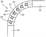
Referring to fig. 1 and 2, there is shown a collapsible table 10 in accordance with the arrangement of the present invention. The retractable table 10 includes a table section 20 that is movable between a deployed position, in which the table section 20 may be generally horizontal, and a stowed position, in which the table section 20 may be non-horizontal, e.g., generally vertical. Fig. 1 and 2 depict the table section 20 in a deployed configuration, while fig. 5c, which will be described in greater detail below, shows the table section 20 in a stowed configuration. It will be appreciated that the table portion 20 may be generally flat and may include an upper surface 24 upon which items may be placed.
The collapsible table 10 further includes a stand 30 that may be slidably received in the groove 40. The recess 40 may receive the retractable table 10 when the retractable table 10 is in the stowed position. The retractable table 10 also includes a plurality of elongated wedge members 50 disposed between the table section 20 and the brackets 30. The wedge member 50 is connected to the table section 20 by a first wedge member 501And a final wedge member 50 connected to the bracket 30nIn turn, are interconnected to each other. Wedge members 50 are elongated and are arranged side-by-side by abutting side surfaces 50a, 50b of adjacent wedge members. Wedge member 50 has a wedge-shaped cross-section such that the side surfaces 50a, 50b of a particular wedge member 50 taper towards each other from the upper surface 50c of the wedge member to the lower surface 50d of the wedge member. Thus, the upper surface 50c may be wider than the lower surface 50 d. The wedge member 50 may thus resemble an arched wedge. The degree to which the wedge members 50 taper and the number of wedge members 50 may be selected depending on the desired difference in the angle of the table portion between the stowed and deployed positions.
The wedge members 50 are rotatably connected to each other. The rotatable connection may allow the side surfaces 50a, 50b of adjacent wedge members to abut when the table section 20 is in the deployed position, and the side surfaces 50a, 50b may move apart when the table section is moved to the stowed position. Adjacent wedge members 50 may rotate about a point 51 where the upper surfaces 50c of the adjacent wedge members meet. First and last wedge members 501、50nMay likewise be attached to table section 20 and brace 30, respectively.
The lower surfaces 50d of the wedge members 50 may each include a tab 54 extending along the length of the wedge member. The tab 54 may be wider than the lower surface 50d such that the tab 54 overlaps the adjacent wedge member lower surface 50 d. The overlap may be sufficient such that gaps between adjacent wedge members are covered by the flap 54 when the table section is in the stowed position. In this manner, the sheet 54 can resemble the skin of armadillo.
In an alternative arrangement, a stretchable membrane, rather than the sheet 54, may be applied to the lower surface 50d of the wedge member and extend throughout the lower surface 50d of the wedge member. The retractable membrane may be extended when the wedge element is extended to the stowed position.
As shown in FIGS. 1 and 2, one or more of the wedge members 50 may include a slot 56 for receiving a writing instrument, such as a pen, stylus, or any other elongated instrument. As depicted, the slot 56 may have a circular hole. Wedge element 50 may include a mechanism configured to lock the writing instrument into a locked position. The writing instrument may be released from the slot 56 by pressing on one end of the writing instrument at the opening of the slot 56.
The upper surface 50c of the wedge member may be curved. The curvature of the upper surface 50c may be such that the curvature of the wedge-shaped element from the brace 30 to the table section 20 is smooth and continuous when the table section 20 is in the deployed position. For example, the gradient of curvature on the upper surface 50c may be equal to the gradient of curvature on the adjacent upper surface 50c where the adjacent wedge members of the upper surface meet and when the table section is in the deployed position.
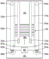
The recess 40 may be provided in the receiving structure 60. The receiving structure may include first and second sidewalls 60a, 60b disposed on either side of the support 30. The cradle 30 is slidably received in the receiving structure 60. As described in more detail below with reference to fig. 6 and 7, an actuator may be provided to selectively slide the carriage 30 in the groove 40. The brackets 30 may be retained in the grooves 40 of the receiving structure 60 when the table section 20 is in the extended and stowed positions. The recess 40 may be sized to receive the bracket 30, wedge member 50 and table portion 20. In the stowed position, the distal end 20a of the table section 20 may be flush with the opening of the recess 40. The receiving structure 60 may form part of a vehicle, in particular a motor vehicle, and the receiving structure 60 may be part of a vehicle interior.
The edge 60c of the recess opening facing the underside 50d of the wedge member 50 may be curved and/or made of a low friction material. Alternatively, the edge 60c of the recess opening facing the underside 50d may comprise a roller. In either case, friction between the receiving structure 60 and the underside of the wedge member 50 may be reduced.
Referring now to fig. 3a and 3b, the collapsible table 10 may further include one or more cables extending from the brackets 30 to the table section 20. The cables may pass through the wedge members 50 and may assist in supporting the table section 20. For example, one or more first cables 72 may pass through the wedge member at or near the upper surface 50c of the wedge member. When the table section 20 is in the extended position, for example, as depicted in figure 3a, the first cable 72 may be under tension. An end of the first cable 72 may be secured to the bracket 30 and the table portion 20. For example, tabs (lug)72a, 72b at the ends of the first cable 72 may be received in corresponding grooves in the bracket 30 and the table portion 20, respectively. The length of the first cable 72 may be selected such that the first cable 72 is under tension when the table section is in the deployed position. The channel may be disposed in the wedge member perpendicular to a longitudinal axis of the wedge member to pass the first cable. The first cable 72 may pass through or near the pivot point 51 between adjacent wedge members 50. Where there is more than one first cable 72, the cables 72 may be spaced along the length of the wedge member.
The retractable table 10 may also include one or more second cables 74 that extend from the brackets 30 to the table section 20. The second cable 74 may pass through the wedge member 50 at or near the lower surface 50d of the wedge member. The second cables 74 may be configured such that they are under tension when the table section 20 is in the stowed position, for example, as depicted in figure 3 b. The second cable 74 may thus prevent the table section 20 from rotating further beyond the stowed position. The second cable 74 may therefore not be under tension when the table section 20 is in the deployed position. The ends of the second cable 74 may be provided with tabs 74a, 74b that may be received in grooves 34a, 34b in the bracket 30 and the table portion 20, respectively. The grooves 34a, 34b may allow the tabs 74a, 74b to slide so that any slack in the second cable 74 may be accommodated when the table portion 20 is in the deployed position. It will be appreciated that one or both of the tabs 74a, 74b may be slidably received in its corresponding groove. The channel may be disposed in the wedge member perpendicular to the longitudinal axis of the wedge member for passage of the second cable. In the case of more than one second cable 74, the cables 74 may be spaced apart along the length of the wedge member.
Referring to fig. 4a and 4b, the collapsible table 10 may include an interlocking structure 80 in addition to or in place of the cables described above. The interlocking structure 80 may include an arm 82 extending from one of the side surfaces 50a, 50b of a particular wedge member. The opposing side surfaces 50a, 50b of adjacent wedge members may include a slot 84 having a shape that receives the arm 82 of the adjacent wedge member 50. The arms 82 and slots 84 may be configured to allow adjacent wedge members 50 to move relative to each other in the manner described above. In particular, the arm 82 may slide in the slot 84. The arms 82 and slots 84 may be curved with the same curvature so that adjacent wedge members may rotate relative to each other. The curvature of the arms and slots 82, 84 may be concentrated at points 51 between the upper surfaces 50c of adjacent wedge members 50. Adjacent wedge members may rotate relative to each other as arms 82 slide in corresponding slots 84. Each interface between adjacent wedge members 50 may be provided with such arms 82 and slots 84. Thus, wedge member 50 is movable from a deployed position (shown in FIG. 4 a) in which side surfaces 50a, 50b abut, to a stowed position (shown in FIG. 4 b) in which side surfaces 50a, 50b are spaced apart.
Each of the arms 82 may include a tab 86 disposed at one end of the arm. The tab 86 may be wider than the rest of the arm 82. The tabs 86 may engage an abutment shoulder 88 in the slot 84. The abutment shoulder 88 may be formed by the wider portion of the slot 84. The interaction between the tabs 86 and the abutment shoulders 88 may constrain movement of adjacent wedge members away from each other. The arm 82 and the slot 84 may be sized such that there is a tight fit between the arm 82 and the slot 84. Such a close fit may help prevent undesired movement between the wedge members.
Referring now to fig. 5a, 5b and 5c, the operation of the collapsible table 10 will now be described. Figure 5a shows the collapsible table in a deployed position where the wedge members 50 and table section 20 are outside of the grooves 40. Wedge member 50 forms a partial arch with the side surfaces 50a, 50b of adjacent wedge members abutting. The table section 20 may be generally horizontal (or may be at another desired angle). The wedge members 50 and the table sections together form a cantilever extending from the receiving structure 60. The bracket 30 is positioned substantially inside the recess 40. When the collapsible table needs to be collapsed, the stand portion 30 may be further lowered into the recess 40. As the bracket 30 is lowered, the underside 50d of the wedge portion interacts with the edge 60c of the receiving structure 60. As the wedge members 50 interact with the edge 60c of the receiving structure 60, the wedge members are successively forced out of abutment with one another. The carriage 30 is set further down, the wedge elements 50 are successively pulled into the grooves 40, and the edge 60c of the receiving structure 60 interacts with the subsequent wedge element 50. The table section 20 moves away from the deployed position and rotates toward the stowed position. Figure 5b illustrates an intermediate position of the collapsible table 10.
As shown in fig. 5c, once the brace 30 is lowered all the way into the recess 40, the wedge members and table section 20 may be fully seated in the recess 40. The distal end 20a of the table section 20 may be flush with the upper edge of the receiving structure 60.
In a similar manner, the table may be moved from the stowed position to the deployed position by lifting the brackets 30 within the grooves 40. The collapsible table 10 may be positioned at an angle, e.g., a small angle, away from the vertical such that as the collapsible table is deployed, gravity acts on the table section 20 to first cause the table section to rotate from the stowed position to the deployed position.
Referring now to fig. 6a and 6b, movement of the carriage 30 may be driven by an actuator, for example in the form of a motor 90. The motor 90 may be operatively connected to the carriage 30 by a pulley mechanism. For example, motor 90 may drive pulleys 92a, 92b via gears 96a, 96b, respectively. The pulleys 92a, 92b may drive the belts 93a, 93b, respectively, the belts 93a, 93b passing over the other pulleys 94a, 94 b. The belts 93a, 93b may be connected to the bracket 30 by connection portions 97a, 97b, respectively. Rotation of the pulley driven by the motor 90 may thus cause the carriage 30 to move linearly within the groove 40. The carriage 30 may thus move up or down in the groove 40 depending on the direction of rotation of the motor 90. The carriage 30 may include one or more guides 32a, 32b that are received in respective channels 33a, 33b in the receiving structure 60. Guides 32a, 32b and channels 33a, 33b limit movement of carriage 30 in a linear direction within groove 40.
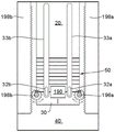
As shown in fig. 6a and 6b, the actuator may be disposed in the recess 40. However, in an alternative arrangement, the actuator may be provided on the support 30. The actuator on the carriage 30 may engage a pulley system, for example, as depicted in fig. 6a and 6 b. Alternatively, an actuator provided on the carriage 30 may engage a rack and pinion type system as described in fig. 7a and 7 b. For example, motor 190 disposed on rack 30 may drive pinions 196a, 196b, pinion 196a, 196b rotatably connected to rack 30. The pinion gears 196a, 196b engage rack portions 198a, 198b, respectively, provided in the receiving structure 60. When the motor 190 drives the pinions 196a, 196b, the pinions move up or down on the racks 198a, 198b and thus slidably move the carriage 30 in the recess 40. A similar rack and pinion type arrangement may be used in the example of fig. 6a and 6b, wherein the actuator is disposed in recess 40.
The controller may be configured to selectively actuate the actuator to move the bracket 30 up or down within the recess 40 and thereby deploy or stow the table section 20. The controller may be operatively connected to a switch or control that a user may use to deploy or stow the table section 20.
Although the table section 20 is shown deployed as a cantilever, it will be appreciated that the distal end 20a of the table section 20 may abut the support member when the table section is in the deployed position. This may be advantageous in situations where the table section 20 is particularly long or where the forces that may be encountered are high.
Also, although not shown, the table portion may include a rotatable cup holder configured to remain in an upright position regardless of the angle of the table portion, e.g., by virtue of a force receiving portion that is lower than the axis of rotation. The gentle rotation of the table portion 20 which benefits from the wedge members advantageously reduces vibration of the cup holder as the table portion rotates.
While the stowable table assembly has been illustrated with reference to one or more examples, it will be appreciated by those skilled in the art that the invention is not limited to the disclosed embodiments and that one or more variations or alternative embodiments of the disclosed embodiments may be constructed without departing from the scope of protection defined by the claims.
Claims (20)
1. A stowable table assembly comprising:
a table portion rotatable between a deployed position and a stowed position;
a bracket configured to be slidably received in the groove; and
a plurality of elongate members disposed between the table portion and the bracket, each of the elongate members having a wedge-shaped cross section such that the elongate members include side surfaces that taper toward each other from an upper surface to a lower surface of the elongate member, a first elongate member coupled to the table portion and a last elongate member coupled to the bracket,
wherein the elongate members are movably coupled to one another such that the side surfaces of adjacent elongate members abut when the table sections are in the unfolded position.
2. The stowable table assembly of claim 1, wherein as the bracket retracts into the groove, the interaction between an edge of the groove opening and the lower surface of the elongate member causes the table portion to move from the deployed position to the stowed position.
3. The stowable table assembly of claim 2, wherein the edge of the groove opening is made of a low friction material.
4. The stowable table assembly of claim 2, wherein the stowable table assembly further comprises an actuator configured to slide the bracket in the groove.
5. The stowable table assembly of claim 4, wherein the stowable table assembly further comprises one or more cables extending from the bracket to the table portion and through the elongate member.
6. The stowable table assembly of claim 5, wherein one or more upper cables pass through the elongated member at or adjacent the upper surface of the elongated member such that the upper cables are under tension when the table portion is in the deployed position.
7. The stowable table assembly of claim 6, wherein one or more lower cables pass through the elongate member at or adjacent the lower surface of the elongate member such that the lower cables limit movement of the table portion beyond the stowed position.
8. The stowable table assembly of claim 7, wherein the elongated members are rotatably coupled to each other.
9. The stowable table assembly of claim 8, wherein the elongated members include one or more arms extending from one of the side surfaces, the arms being slidably received in one or more corresponding slots disposed in adjacent elongated members.
10. The stowable table assembly of claim 9, wherein the arm and slot are curved.
11. The stowable table assembly of claim 10, wherein said arms and slots are curved with a center of curvature that generally coincides with the second edge of the upper surface of the respective elongate member.
12. The stowable table assembly of claim 9, wherein each arm includes a tab disposed at one end of the arm, the tab configured to engage an abutment shoulder in one of the slots, wherein a second interaction between the tab and abutment shoulder limits movement of adjacent tapered surfaces away from each other.
13. The stowable table assembly of claim 12, wherein adjacent edges of the upper surface of adjacent elongate members abut in the stowed and deployed positions.
14. The stowable table assembly of claim 13, wherein adjacent edges of the lower surface of adjacent elongate members are spaced apart in the stowed position.
15. The stowable table assembly of claim 14, wherein the upper surface of the elongated member is curved.
16. The stowable table assembly of claim 15, wherein the curvature of the upper surface of the elongate member is continuous throughout adjacent elongate members.
17. The stowable table assembly of claim 16, wherein each of the elongate members has a tab applied to the lower surface of each of the elongate members, the tab of a particular elongate member configured to overlap an adjacent elongate member when the table section is in the stowed position.
18. The stowable table assembly of claim 17, wherein a retractable membrane is applied to and extends across the lower surface of the elongated member.
19. The stowable table assembly of claim 18, wherein a flexible material extends over the upper surface of the elongated member.
20. The stowable table assembly of claim 1, wherein one or more of the elongated members includes a slot for receiving a writing instrument.
Applications Claiming Priority (2)
| Application Number | Priority Date | Filing Date | Title |
|---|---|---|---|
| GB1522757.2A GB2538823B (en) | 2015-12-23 | 2015-12-23 | Stowable table assembly |
| GB1522757.2 | 2015-12-23 |
Publications (2)
| Publication Number | Publication Date |
|---|---|
| CN106901497A CN106901497A (en) | 2017-06-30 |
| CN106901497B true CN106901497B (en) | 2021-08-06 |
Family
ID=55311527
Family Applications (1)
| Application Number | Title | Priority Date | Filing Date |
|---|---|---|---|
| CN201611189170.4A Active CN106901497B (en) | 2015-12-23 | 2016-12-21 | Foldable table assembly |
Country Status (4)
| Country | Link |
|---|---|
| US (1) | US10070717B2 (en) |
| CN (1) | CN106901497B (en) |
| DE (1) | DE102016123510A1 (en) |
| GB (1) | GB2538823B (en) |
Families Citing this family (19)
| Publication number | Priority date | Publication date | Assignee | Title |
|---|---|---|---|---|
| DE102017211572A1 (en) * | 2017-02-17 | 2018-08-23 | Brose Fahrzeugteile Gmbh & Co. Kommanditgesellschaft, Coburg | Storage arrangement for a vehicle |
| FR3066083B1 (en) * | 2017-05-12 | 2019-04-19 | Peugeot Citroen Automobiles Sa | RETRACTABLE FABRIC TABLE WITH ROLL-TYPE MECHANISM |
| US10322656B2 (en) * | 2017-07-28 | 2019-06-18 | GM Global Technology Operations LLC | Folding furniture piece system and method |
| GB2566012B (en) * | 2017-08-24 | 2020-05-06 | Ford Global Tech Llc | Vehicle furniture system |
| US10737636B2 (en) * | 2018-01-31 | 2020-08-11 | Shanghai Yanfeng Jinqiao Automotive Trim Systems Co. Ltd. | Vehicle interior component |
| DE102018202628A1 (en) * | 2018-02-21 | 2019-08-22 | Bayerische Motoren Werke Aktiengesellschaft | Storage device and motor vehicle |
| KR102064567B1 (en) * | 2018-04-12 | 2020-01-10 | 현대자동차(주) | Console apparatus with variable table |
| LT6702B (en) * | 2018-06-26 | 2020-02-25 | UAB "Adolesa" | Structural furniture element |
| DE102018212085A1 (en) * | 2018-07-19 | 2020-01-23 | Brose Fahrzeugteile Gmbh & Co. Kommanditgesellschaft, Coburg | Adjustment assembly for a vehicle with a swiveling table element |
| FR3087401B1 (en) * | 2018-10-23 | 2022-02-11 | Faurecia Interieur Ind | TRIM ELEMENT COMPRISING A DEFORMABLE PANEL FORMING A SUPPORT SURFACE IN A DEPLOYED POSITION |
| DE102018132165A1 (en) * | 2018-12-13 | 2020-06-18 | Bayerische Motoren Werke Aktiengesellschaft | Storage device and vehicle |
| DE102018132164A1 (en) | 2018-12-13 | 2020-06-18 | Bayerische Motoren Werke Aktiengesellschaft | Storage device and vehicle |
| DE102018132163A1 (en) | 2018-12-13 | 2020-06-18 | Bayerische Motoren Werke Aktiengesellschaft | Storage device and vehicle |
| FR3092056B1 (en) | 2019-01-24 | 2021-01-08 | Faurecia Interieur Ind | Vehicle interior component, comprising a retractable shelf |
| US11820258B2 (en) | 2019-04-01 | 2023-11-21 | Adient Us Llc | Flexible structural component and use |
| WO2020252253A1 (en) | 2019-06-12 | 2020-12-17 | Shanghai Yanfeng Jinqiao Automotive Trim Systems Co. Ltd. | Vehicle component |
| CN110934417B (en) * | 2019-10-29 | 2022-05-13 | 厦门新技术集成有限公司 | Simple folding table |
| CN112617427A (en) * | 2020-12-10 | 2021-04-09 | 浙江建设职业技术学院 | Practical training classroom structure for building major teaching and practical training drawing table |
| US11970137B2 (en) | 2022-09-06 | 2024-04-30 | Ford Global Technologies, Llc | Vehicle having a storage compartment with a deployable shelf |
Citations (9)
| Publication number | Priority date | Publication date | Assignee | Title |
|---|---|---|---|---|
| US542139A (en) * | 1895-07-02 | Extension-table | ||
| US1980659A (en) * | 1932-11-11 | 1934-11-13 | Boldt Johannes | Note-block |
| US2869956A (en) * | 1957-05-13 | 1959-01-20 | Saginaw Furniture Shops Inc | Extension commode |
| US3034757A (en) * | 1959-12-23 | 1962-05-15 | Max Caplan | Bracket mounting for tables and the like |
| CN2364739Y (en) * | 1999-04-02 | 2000-02-23 | 海尔集团公司 | Sliding dinning table |
| DE202004003216U1 (en) * | 2003-06-18 | 2004-11-18 | Gumpert, Heinz | Table top which can be rolled up comprises strips of cover material glued to cloth layer, under which support slats with trapezium-shaped cross-section are glued with their shorter sides pointing away from it |
| CN202027076U (en) * | 2011-03-22 | 2011-11-09 | 崔自成 | Telescopic office desk |
| CN204383286U (en) * | 2015-01-12 | 2015-06-10 | 攀枝花市天永成工贸有限公司 | A kind of environmental protection tarpaulin automatic capping device for dumping car/lorry |
| CN204409984U (en) * | 2015-02-09 | 2015-06-24 | 温州职业技术学院 | A kind of folding table |
Family Cites Families (37)
| Publication number | Priority date | Publication date | Assignee | Title |
|---|---|---|---|---|
| US508938A (en) * | 1893-11-21 | Eddie h | ||
| US492284A (en) * | 1893-02-21 | Extension-table | ||
| US2778698A (en) * | 1957-01-22 | La butte | ||
| US228066A (en) * | 1880-05-25 | Extension-table | ||
| US472881A (en) * | 1892-04-12 | Extension-table | ||
| US963502A (en) * | 1909-11-20 | 1910-07-05 | Stokeley Marshal Bond | Foldable table. |
| US1566200A (en) * | 1924-10-11 | 1925-12-15 | Henry O Girard | Wall table |
| US1950927A (en) * | 1930-07-08 | 1934-03-13 | Mcmillan William | Flexible cover for vehicles |
| US2262719A (en) * | 1939-01-18 | 1941-11-11 | Barber Colman Co | Closure operator control system |
| US2726911A (en) * | 1954-06-18 | 1955-12-13 | Samuel J Mason | Roll top extension table |
| US2771319A (en) * | 1955-03-07 | 1956-11-20 | Mervin J Renquist | Combination truck body and flexible cover therefor |
| US2848291A (en) * | 1955-08-15 | 1958-08-19 | Steel Slides Inc | Table construction having retractile top portion |
| US2909718A (en) * | 1955-08-26 | 1959-10-20 | Julius J Lawick | Door operating apparatus |
| US3129752A (en) * | 1960-11-25 | 1964-04-21 | Whiting Mfg Inc T | Sliding door |
| US3299570A (en) * | 1964-12-03 | 1967-01-24 | Richard S Radcliffe | Canopy |
| FR1427200A (en) * | 1964-12-24 | 1966-02-04 | Giblin Lavault & Cie Ets | Retractable table cabinet |
| FR1430011A (en) * | 1965-04-20 | 1966-02-25 | Aseguinolaza Hermanos S R C | Retracting device for element table |
| BE887062Q (en) * | 1967-01-20 | 1981-05-04 | Teisseire Henri | RETRACTABLE TABLE |
| US3884159A (en) * | 1973-11-19 | 1975-05-20 | Carmen V Faria | Folding table |
| US4795206A (en) * | 1986-07-11 | 1989-01-03 | Adelco, Inc. | Pickup truck bed cover system |
| DE8913557U1 (en) * | 1989-11-16 | 1989-12-28 | Rehau Ag + Co, 8673 Rehau, De | |
| US5277240A (en) * | 1990-04-24 | 1994-01-11 | Tebel Pneumatiek B.V. | Overhead door assembly |
| FR2742102B1 (en) * | 1995-12-08 | 1998-01-30 | Peugeot | ARRANGEMENT OF A TABLET IN A BOX OF A MOTOR VEHICLE |
| JP2851267B2 (en) * | 1996-08-09 | 1999-01-27 | パーク クワン−スー | Automatic lifting device for computer monitor box |
| EP0967359A3 (en) * | 1998-06-26 | 2000-09-27 | Ceraper, S.L. | Improvements in operating devices and slats for reversible window blinds |
| DE19935762B4 (en) * | 1999-07-27 | 2004-04-22 | Norbert Uch | link plate |
| CN2521086Y (en) * | 2002-01-16 | 2002-11-20 | 南江 | Vehicle seat capable of constituting a desk |
| US6733094B1 (en) * | 2002-11-13 | 2004-05-11 | Chun-Chung Chang | Lifting device for LCD |
| US20060225624A1 (en) * | 2005-04-07 | 2006-10-12 | Grace Daniel R | Knockdown table assembly having trash bag holder |
| US8348080B2 (en) * | 2006-10-16 | 2013-01-08 | Baptiste George H | Trash container with retractable weatherproof cover |
| US7836832B2 (en) * | 2007-02-13 | 2010-11-23 | Paccar Inc | Stowable fold-out/roll-out dinette table assembly |
| GB0706776D0 (en) * | 2007-04-05 | 2007-05-16 | Premium Aircraft Interiors Uk | Movable furniture |
| DE102008018195A1 (en) * | 2007-04-27 | 2008-10-30 | Ford-Werke Gmbh | Seat arrangement for motor vehicle, is equipped with folding table which can also be used as coat hanger |
| US8205563B2 (en) * | 2009-06-29 | 2012-06-26 | St. Louis Designs, Inc. | Aircraft table system with rolling sled member |
| KR101834468B1 (en) * | 2010-05-18 | 2018-03-05 | 아리아 엔터프라이시스, 인크. | Portable, compact folding furniture pieces |
| US8528996B2 (en) * | 2010-11-29 | 2013-09-10 | Newmar Corporation | Expandable table arrangement and the like, especially suited for use in recreational vehicles |
| US20160331125A1 (en) * | 2015-05-16 | 2016-11-17 | Rockpaperrobot Inc. | Wall Mounted Deployable Furniture Piece |
-
2015
- 2015-12-23 GB GB1522757.2A patent/GB2538823B/en active Active
-
2016
- 2016-11-30 US US15/365,176 patent/US10070717B2/en active Active
- 2016-12-06 DE DE102016123510.5A patent/DE102016123510A1/en active Pending
- 2016-12-21 CN CN201611189170.4A patent/CN106901497B/en active Active
Patent Citations (9)
| Publication number | Priority date | Publication date | Assignee | Title |
|---|---|---|---|---|
| US542139A (en) * | 1895-07-02 | Extension-table | ||
| US1980659A (en) * | 1932-11-11 | 1934-11-13 | Boldt Johannes | Note-block |
| US2869956A (en) * | 1957-05-13 | 1959-01-20 | Saginaw Furniture Shops Inc | Extension commode |
| US3034757A (en) * | 1959-12-23 | 1962-05-15 | Max Caplan | Bracket mounting for tables and the like |
| CN2364739Y (en) * | 1999-04-02 | 2000-02-23 | 海尔集团公司 | Sliding dinning table |
| DE202004003216U1 (en) * | 2003-06-18 | 2004-11-18 | Gumpert, Heinz | Table top which can be rolled up comprises strips of cover material glued to cloth layer, under which support slats with trapezium-shaped cross-section are glued with their shorter sides pointing away from it |
| CN202027076U (en) * | 2011-03-22 | 2011-11-09 | 崔自成 | Telescopic office desk |
| CN204383286U (en) * | 2015-01-12 | 2015-06-10 | 攀枝花市天永成工贸有限公司 | A kind of environmental protection tarpaulin automatic capping device for dumping car/lorry |
| CN204409984U (en) * | 2015-02-09 | 2015-06-24 | 温州职业技术学院 | A kind of folding table |
Also Published As
| Publication number | Publication date |
|---|---|
| GB201522757D0 (en) | 2016-02-03 |
| DE102016123510A1 (en) | 2017-06-29 |
| US10070717B2 (en) | 2018-09-11 |
| GB2538823B (en) | 2018-09-26 |
| CN106901497A (en) | 2017-06-30 |
| GB2538823A (en) | 2016-11-30 |
| US20170181536A1 (en) | 2017-06-29 |
Similar Documents
| Publication | Publication Date | Title |
|---|---|---|
| CN106901497B (en) | Foldable table assembly | |
| ES2672386T3 (en) | Folding table | |
| DK2926688T3 (en) | Foldable, mechanically operated table stand | |
| CN107864648B (en) | Folding table | |
| JP5144668B2 (en) | Drawable guide assembly for drawer | |
| KR102518234B1 (en) | Variable rear spoiler apparatus of rear bumper for vehicle | |
| KR101904399B1 (en) | seat back table in vehicle | |
| EP3412573B1 (en) | Expandable seat for a vehicle | |
| US20150121771A1 (en) | Seating sytem with tiltable deck and belt drive | |
| EP2698281B1 (en) | Vehicle equipped with a luggage compartment having a height-adjustable loading floor | |
| CN110074544A (en) | Retractable assembly for table for vehicle | |
| CN108790964B (en) | Electric seat adjusting mechanism and vehicle | |
| US10368648B2 (en) | Deployable footrest | |
| KR200492097Y1 (en) | Furniture with Variable Auxiliary Table | |
| US9630661B1 (en) | Retractable roof stored under an active spoiler | |
| JP4261499B2 (en) | Vehicle table structure | |
| CN106088799A (en) | Tent eave hack lever mechanism | |
| CN114856255A (en) | Multifunctional intelligent mobile cabin capable of quickly multiplying space | |
| US10889248B2 (en) | System for covering the luggage compartment of a motor vehicle | |
| KR102566360B1 (en) | Sliding bracket device for guide motor | |
| EP2229074B1 (en) | Extensible table with improved extension mechanism | |
| SE1050374A1 (en) | Arrangement at glazed balcony | |
| KR101702540B1 (en) | Sliding retractable drag reducer assembly | |
| CN208473670U (en) | The resistance mechanism of curtain rope body | |
| CN110641926B (en) | Carrying device |
Legal Events
| Date | Code | Title | Description |
|---|---|---|---|
| PB01 | Publication | ||
| PB01 | Publication | ||
| SE01 | Entry into force of request for substantive examination | ||
| SE01 | Entry into force of request for substantive examination | ||
| GR01 | Patent grant | ||
| GR01 | Patent grant |