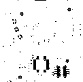
Fig. 1 is the end view of caulking anchor clamps;
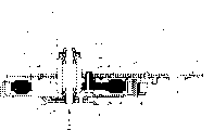
Fig. 2 (a) is the plane graph of a kind of stator structure in the relevant work;
Fig. 2 (b) is the end view of stator structure shown in Fig. 2 (a);
Fig. 3 (a) is the schematic diagram that is used for illustrating the caulking process to 3 (c);
With reference to figure 2 (a) and 2 (b), stator substrate 114 is formed by stacking by the printed circuit board (PCB) 107 that a magnetic sheet 108 (the zinc steel disc is made) and is equipped with a plurality of electronic components 106 on it.A plurality of caulking part 101a, 101b, 101c and 101d are arranged on the printed circuit board (PCB) 107.
To caulking part 101a, 101b has used caulking anchor clamps 104 as shown in Figure 1 when the burr part 115 of 101c and 101d is carried out the caulking operation.Wherein reference character 110 is represented a caulking pin, and 109 then represent a caulking support, and it is used for preventing that stator substrate 114 is moved in the caulking process.
To 3 (c), a typical caulking pin 110 and burr part 115 have wherein been described with reference to figure 3 (a).By pushing of caulking pin 110, can be to caulking part 101a, 101b, a plurality of burr parts 115 of 101c and 101d are carried out caulkings, and caulking pin 110 is arranged on the caulking anchor clamps 104 place corresponding to stator substrate 114 each burr part 115.On the dead zone 103 of printed circuit board (PCB) 107, do not have electronic component 106, thereby it can be used to be supported by support 109.
With reference to figure 2 (a) and 2 (b), it is the smooth border circular areas of 20mm that reference character 111 is represented a diameter, and its center is corresponding to center of gravity 105 (being called the caulking center of gravity), and this center of gravity is by caulking part 101a, 101b, and 101c and 101d determine.But smooth border circular areas 111 can not be used for being supported by caulking support 109, because some electronic components 106 are arranged in smooth border circular areas 111, caulking support 109 can only be placed on the dead zone 103.
In general, in the stator substrate 114 that is formed by caulking by printed circuit board (PCB) 107 and magnetic sheet 108, the accuracy to size of printed circuit board (PCB) 107 is lower than the accuracy of magnetic sheet 108.Therefore, printed circuit board (PCB) 107 is easily because of adopting the method that burr part 115 is carried out caulking to be out of shape or bending.
In the relevant technologies shown in Fig. 2 (a) and 2 (b), can come caulking part 101a and 101d are carried out caulking with higher accuracy to size, but, caulking part 101b and 101c are then not all right, its reason is because distortion and crooked has taken place printed circuit board (PCB) 107, this will cause occurring between printed circuit board (PCB) 107 and the magnetic sheet 108 space, and its result will cause the stator substrate 114 and the rotor 112 of motor to bump.
With reference to figure 1,3 (a) to 3 (c) and Fig. 4 to Fig. 7, they have been described in detail the described motor of first preferred embodiment of the present invention, wherein the reference character of same section is identical with reference character in the relevant technologies, it is described in detail in this memorandum.
Fig. 4 is the plane graph that adopts a kind of VTR (video tape recorder) capstan motor of the described stator structure of first preferred embodiment of the present invention.
Fig. 5 is the end view of capstan motor shown in Figure 4;
Fig. 6 is a plane graph, and it has shown a plane that is used for installing electronic component on capstan motor;
Fig. 7 is the plane graph of the described stator structure of first preferred embodiment of the present invention;
With reference to figure 4 and Fig. 5, the capstan motor of the described VTR of first preferred embodiment of a kind of the present invention of being used for is made of 24 grooves and 16 magnetic poles.Around the outer ring of rotor 112, the Magnetic Sensor 113 of a plurality of MR elements is arranged.Stator substrate 114 has the double-decker of printed circuit board (PCB) 107 and zinc steel disc (as magnetic sheet) 108, and these two layers are by four caulking part 101a, and 101b, 101c, 101d are connected to an integral body.
During caulking,, just can determine in the stator substrate 104 by caulking part 101a 101b, the caulking center of gravity (center of gravity) 105 that 101c, 101d decide with reference to figure 7 and by following calculating.
On printed circuit board (PCB) 107, the flat circular part 111 that a diameter is arranged is 20mm, its center is corresponding to above-mentioned caulking center of gravity 105, and do not have electronic component 106 on the circular portion 111.
With reference to figure 1, the caulking pin 110 of caulking anchor clamps 104 is placed with the caulking part 101a towards stator substrate 114,101b, 101c, 101d again.The end of caulking support 109 has a level and smooth surface and is placed on the circular portion 111 in the caulking anchor clamps 104.The center of circular portion 111 is corresponding to caulking center of gravity 105, and it allows with fixture support on printed circuit board (PCB) 107.
Shown in Fig. 3 (a), a plurality of burr parts 115 are used as the part of zinc steel disc 108 and form, and they are outstanding slightly from the printed circuit board (PCB) 107.The caulking pin 110 of caulking anchor clamps 104 is placed with towards burr part 115.Shown in Fig. 3 (b), burr part 115 is depressed from printed circuit board side by the caulking pin 110 of caulking anchor clamps 104, and it is flat that its result makes burr part 115 be twisted with the fingers, shown in Fig. 3 (c).In this example, caulking work is finished by supporting stator substrate 114 with caulking support 109.Therefore, printed circuit board (PCB) 107 and zinc steel disc 108 can be linked together with higher accuracy to size.
As mentioned above, a plurality of caulking part 101a, 101b, 101c, therefore 101d is by supporting the center of gravity 105 of stator substrate 114 with caulking support 109 and depress four caulking pin 110 simultaneously and twisted with the fingers flatly simultaneously, can preventing that printed circuit board (PCB) 107 from producing distortion, bending and inclination when caulking.
Below will provide explanation to how determining caulking center of gravity 105.
When with caulking part 101a as initial point (0,0) and from initial point to each caulking part 101b, 101c, the distance of 101d (mm) with coordinate (X when Y) representing, is exemplified below:
Caulking part 101b:(43.5,14.0)
Caulking part 101c:(45.6,60.4)
Caulking part 101d:(1.3,56.5)
Therefore, when with coordinate (X, when Y) representing caulking center of gravity 105, then coordinate X and coordinate Y are expressed as follows respectively:
X=1/4(0+43.5+45.6+1.3)=22.6
Y=1/4(0+14.0+60.4+56.5)=32.73
So coordinate can be used in the position of caulking center of gravity 105, and (X Y)=(22.6,33.73) determines.As mentioned above, be not have electronic component 106 on 20mm, center and the caulking center of gravity 105 corresponding border circular areas 111 at diameter.The diameter of caulking support 109 is slightly smaller than border circular areas 111.Thereby caulking support 109 will can not touch electronic component 106, but also can support printed circuit board (PCB) 107 effectively.
Need not many speeches, the size of border circular areas 111 can be determined arbitrarily, and the size of caulking support 109 diameters is also decided according to the number of caulking part 101 and the size of printed circuit board (PCB).
As mentioned above, according to stator structure of the present invention, its stator substrate has the double-decker of printed circuit board (PCB) and zinc steel disc, and these two layers partly are joined together by four caulkings.Simultaneously, these four caulking parts have also been determined the caulking center of gravity.The diameter in planar rondure zone is 20mm, and its center does not have electronic component corresponding to the caulking center of gravity in border circular areas.During caulking,, just can finish being positioned at the caulking work of the peripheral caulking part of border circular areas by with caulking stent support border circular areas.Therefore, each the caulking part in the printed circuit board (PCB) can be depressed by caulking pin equalization, thereby has avoided the distortion and the inclination of printed circuit board (PCB).
Can prevent the distortion and the inclination of printed circuit board (PCB) according to stator structure of the present invention.Therefore, flat board is made in the stator substrate, the stator substrate is not contacted with rotor, nor vibration can occur owing to space between printed circuit board (PCB) distortion or magnetic sheet that tilts to cause and the printed circuit board (PCB).
In addition, do not need extra-pay according to method of the present invention (that is, in center and the corresponding border circular areas of caulking center of gravity, not placing electronic component), because its printed circuit board (PCB) can adopt former method to design and process.
Next, will describe second described brushless electric machine of preferred embodiment of the present invention with reference to figure 8 to Figure 10.
Fig. 8 is the profile of second described brushless electric machine of preferred embodiment of the present invention;
Fig. 9 is the plane graph on arrow 2 directions of brushless electric machine shown in Figure 8, and from then on rotor is wherein shifted out in the brushless electric machine;
Figure 10 is the plane graph of brushless electric machine shown in Figure 9, has wherein illustrated how partly to come to determine the caulking center of gravity according to caulking.
As shown in Figure 8, second described brushless electric machine 1 of preferred embodiment generally is made of rotor 10 and stator 20 according to the present invention.Rotor 10 comprises: a rotor yoke 11, a capstan 12 that is positioned at rotor yoke 11 centers, be positioned at rotor yoke 11 inner edges drive magnet 13 all around, frequency generation magnet (being called FG magnet) 14 and be positioned at rotor yoke 11 centers and be used to drive the belt pulley 15 of external equipment, and a support 12 that is positioned at capstan 12 middle parts.
Stator 20 comprises: the printed circuit board (PCB) 22, that a motor base 21, overlays motor base 21 bottoms contains the support of bearing 23 of stylolitic part 23a and flange 24, and a stator coil assembly 25.The stylolitic part 23a of the support of bearing 23 has penetrated printed circuit board (PCB) 22 and motor base 21.Printed circuit board (PCB) 22 and motor base 21 all are installed in the upper surface of flange 24, and stator coil assembly 25 then is installed in the lower surface of flange 24.
Reference character 21a represents the ledge in the motor base 21, and it is used to contact electronic component.27a and 27b are oilless bearings, and they can support the rotation of capstan 12.28 is screws that are used to install the support of bearing 23, and 29 is the thrust caps between the support of bearing 23 and support 16, and P is the pinch roller that drives tape with capstan 12.
With reference to figure 9, a magnetoresistive element (being called the MR element) 32 and IC (integrated circuit) 33 are installed on printed circuit board (PCB) 22 and also have a coupling part 34.
Stator coil assembly 25 is made of a toroidal core 36 and the stator coil 37 that is wrapped on the toroidal core 36.
Specifically, toroidal core 36 contains the outstanding hole 36a that is useful on a plurality of stator coils 37 of winding, is used for the annular section 36b that is connected with the inner edge of outstanding hole 36a.Three mounting bar 36c are arranged on the annular section 36b, and they stretch to the center of annular section 36b to be used for connection.In addition, reference character 36d represents installing hole, and 36e is the ledge that is used for caulking, and 36f, 36g are the caulking parts.
The terminal 37a of each stator coil 37 is connected on each coupling part 34, is connected thereby produce electronics with printed circuit board (PCB) 22.
In addition, reference character 24a represents the motor base mounting portion in the flange 24, and 24b then represents the magnetic core mounting portion in the flange 24.
With reference to Figure 10, second described brushless electric machine of preferred embodiment of the present invention has the stator structure identical with first preferred embodiment outer ring.
Identical with the explanation that first preferred embodiment is done, in second described stator structure of preferred embodiment of the present invention, stator substrate 114 has the double-decker of printed circuit board (PCB) 22 and motor base 21 (being made by the zinc steel disc), and these two layers are at four caulking part 101a, 101b, 101c, spliced together in the 101d place.Simultaneously, these four caulking part 101a, 101b, 101c, 101d have also determined caulking center of gravity 105.In being the corresponding border circular areas 111 of 20mm, center and caulking center of gravity, its diameter do not have electronic component 106.During caulking, support border circular areas 111, just can finish being positioned at the caulking part 101a of border circular areas 111 peripheries, 101b, 101c, the caulking work of 101d by caulking support 109 with caulking anchor clamps 104 shown in Figure 1.Therefore, each the caulking part 101a in the printed circuit board (PCB), 101b, 101c, 101d can be depressed by each caulking pin 110 equalizations of caulking anchor clamps 104, thereby has avoided the distortion and the inclination of printed circuit board (PCB) 22.
Next, will describe design feature among the present invention and efficient.
In annular section 36h, a fan-shaped partition C is arranged between its mounting bar 36c and the 36c, thereby printed circuit board (PCB) 22 parts are exposed.On the exposed portions serve of printed circuit board (PCB) 22, be formed with coupling part 34.Therefore, the terminal 37a and the coupling part 34 of stator coil 37 directly can be coupled together, thereby can be assembled into an effective brushless electric machine assembly and a reliable brushless electric machine.
Three mounting bar 36c are arranged among the annular section 36b of toroidal core 36, and they stretch to the center position of annular section 36b with identical angle intervals.Motor base mounting portion 24a is arranged on the flange 24, and they and adjacent mounting bar 36c have the angle same distance, and magnetic core mounting portion 24b also is like this.During assembling brushless electric machine 1, the motor mounting part that printed circuit board (PCB) 22 and motor base 21 are installed in flange 24 together divides on the 24a, and toroidal core 36 then is installed on the magnetic core mounting portion 24b of flange 24 by screw 28.Therefore, when in motor base 21 toroidal core 36 and the support of bearing 23 being installed, the installation site of toroidal core 36 and motor base 21 can choose at random on the circumferencial direction of annular section 36b.These characteristics make the installation of brushless electric machine 1 become very simple.
In addition, reduce in order not make the magnetic circuit that causes because of reservation caulking part 36g, stretched out semicircular ledge 36e from annular section 36b to its center, it can be used for caulking.Its result makes and does not change apart from the magnetic circuit of the nearer outstanding magnetic pole 36a of caulking part 36g and apart from the magnetic resistance between the magnetic circuit of caulking part 36g outstanding magnetic pole 36a far away.Therefore, just can prevent that the magnetic characteristic in stator 20 magnetic circuits from changing, thereby reduce the uneven phenomenon of torque that is produced in the brushless electric machine 1.
When using brushless electric machine in an equipment, the pressure direction of pinch roller P (representing with arrow A) is to stretch to one of mounting bar 36c from one of motor base mounting portion 24a along straight line L.Therefore, can prevent that brushless electric machine 1 from by pinch roller P integral inclination being taken place when the rectilinear direction L of arrow A promotes at its capstan 12.
According to of the present invention, the assembling of motor should make the flange of the support of bearing place motor base and a plurality of mounting bar and under printed circuit board (PCB) between, and each end of stator coil is also linked to each other with each terminal part on the printed circuit board (PCB) respectively, and printed circuit board (PCB) should partly expose from the part of the partition between a plurality of mounting bars of annular section.Therefore, when being installed to toroidal core and the support of bearing on the motor base, the mounting portion of toroidal core and motor can determine that arbitrarily these characteristics make the assembling of motor become very simple along the circumference of annular section.
In addition, according to of the present invention, the pinch roller of equipment is along the capstan of a vertical pushing motor of rectilinear direction from capstan to one of a plurality of mounting bars.
Therefore, can prevent effectively that the capstan that causes owing to thrust that pinch roller applies from tilting.