CN106869883B - Automatic oil supply and discharge device and method - Google Patents
Automatic oil supply and discharge device and method Download PDFInfo
- Publication number
- CN106869883B CN106869883B CN201710087311.XA CN201710087311A CN106869883B CN 106869883 B CN106869883 B CN 106869883B CN 201710087311 A CN201710087311 A CN 201710087311A CN 106869883 B CN106869883 B CN 106869883B
- Authority
- CN
- China
- Prior art keywords
- valve
- oil
- pipeline
- discharge
- tank
- Prior art date
- Legal status (The legal status is an assumption and is not a legal conclusion. Google has not performed a legal analysis and makes no representation as to the accuracy of the status listed.)
- Active
Links
Images
Classifications
-
- E—FIXED CONSTRUCTIONS
- E21—EARTH DRILLING; MINING
- E21B—EARTH DRILLING, e.g. DEEP DRILLING; OBTAINING OIL, GAS, WATER, SOLUBLE OR MELTABLE MATERIALS OR A SLURRY OF MINERALS FROM WELLS
- E21B43/00—Methods or apparatus for obtaining oil, gas, water, soluble or meltable materials or a slurry of minerals from wells
- E21B43/16—Enhanced recovery methods for obtaining hydrocarbons
- E21B43/24—Enhanced recovery methods for obtaining hydrocarbons using heat, e.g. steam injection
Abstract
The invention provides an automatic oil supply and discharge device and method, comprising the following steps: a discharge tank, a discharge pump, and a feed pump; the oil discharge tank is provided with an oil discharge tank outlet and an oil discharge tank inlet; the oil discharge pump is provided with a first tee joint, and the first tee joint is connected with an outlet of the oil discharge tank through a pipeline provided with a seventh valve and is connected with an outlet of the oil storage tank through a first oil discharge pipeline provided with a first valve; the oil supply pump is provided with a second tee joint, the second tee joint is connected with an inlet of the oil discharge tank through a pipeline provided with an eighth valve, and is connected with an outlet of the burner through a second oil discharge pipeline provided with a fifth valve; the inlet of the oil storage tank is connected with the inlet of the oil discharge tank through a pipeline provided with a fourth valve and an eighth valve; the first oil discharging pipeline and the second oil discharging pipeline are communicated through a communication pipeline provided with a sixth valve, one end of the communication pipeline is communicated with the first oil discharging pipeline between the first valve and the outlet of the oil storage tank, and the other end of the communication pipeline is communicated with the second oil discharging pipeline between the fifth valve and the outlet of the combustor.
Description
Technical Field
The invention relates to the technical field of machinery, in particular to an automatic oil supply and discharge device.
Background
The heat recovery of thick oil is a mature oil recovery process in oil field, in which the steam injection boiler of oil field is a key device for heat recovery of thick oil, and its function is to heat water by heat released from combustion of fuel furnace, then to inject steam with a certain pressure and temperature into developed oil layer, so as to reduce viscosity of thick oil, and benefit to thick oil recovery.
The application of the oilfield steam injection boiler, in particular to the oilfield field special wet steam generator is more and more extensive, and the corresponding auxiliary supporting facilities are as many as dozens. The current oil field movable steam injection boiler fuel system comprises a fuel discharge tank, a fuel discharge pump, an oil storage tank, a fuel pump house and the like, and mainly has the following problems:
and (3) a step of: the equipment is matched with a lot of equipment, which is unfavorable for the flexible maneuvering of the whole construction. The oil discharge tank and the oil discharge pump need to be moved for one vehicle number, and the oil pump house needs to be moved for one vehicle number, so that the mobility is poor.
And II: the safety risk points are numerous, and the investment of hidden danger treatment is increased. The supporting facilities need reliable grounding, the oil pump house needs explosion protection, forced ventilation, combustible gas detection and other safety risk points, and the investment of hidden danger treatment needs to be increased.
Thirdly,: the process equipment is complex and tedious, and the daily maintenance cost is greatly increased.
Fourth, the method comprises the following steps: the field requirements are 40m multiplied by 50m,90% of the oilfield fields can not meet the requirements of the existing equipment placement standards, and the field leveling investment is large.
From the analysis, the existing movable oilfield steam injection boiler is complex in structure, and has high working labor intensity, long time consumption and more risk hidden trouble points under the working condition of frequent movement according to production requirements.
Disclosure of Invention
Aiming at the problems of complex structure and inconvenient transportation of the oilfield steam injection boiler in the prior art, the invention aims to provide an automatic oil supply and discharge device and method with more reasonable structure.
In order to solve the above problems, an embodiment of the present invention provides an automatic oil supply and discharge device, including: an oilfield steam injection boiler, comprising: a discharge tank, a discharge pump, and a feed pump;
wherein the oil discharge tank is provided with an oil discharge tank outlet and an oil discharge tank inlet;
the oil discharge pump is provided with a first tee joint, and the first tee joint is connected with an oil discharge tank outlet through a pipeline provided with a seventh valve and is connected with an oil storage tank outlet through a first oil discharge pipeline provided with a first valve; the oil supply pump is provided with a second tee joint, and the second tee joint is connected with an inlet of the oil discharge tank through a pipeline provided with an eighth valve and is connected with an outlet of the burner through a second oil discharge pipeline provided with a fifth valve; wherein the inlet of the oil storage tank is connected with the inlet of the oil discharge tank through a pipeline provided with a fourth valve and an eighth valve; the first oil discharging pipeline and the second oil discharging pipeline are communicated through a communication pipeline provided with a sixth valve, one end of the communication pipeline is communicated with the first oil discharging pipeline between the first valve and the outlet of the oil storage tank, and the other end of the communication pipeline is communicated with the second oil discharging pipeline between the fifth valve and the outlet of the combustor.
The device comprises a first oil discharge tank, a second oil discharge tank, a third oil discharge tank, a fourth oil discharge tank, a fifth oil discharge tank, a sixth oil discharge tank, a seventh oil discharge tank, a fourth oil discharge tank, a fifth oil discharge tank, a sixth oil discharge tank, a seventh oil discharge tank and a fourth oil discharge tank, wherein the fourth oil discharge tank is connected with the fourth oil discharge tank through an eleventh valve; the first tee joint is connected with a first sweeping bypass line in parallel, and a second valve is arranged on the first sweeping bypass line; the second tee joint of the oil feed pump is connected with a second sweeping bypass line in parallel, and a third valve is arranged on the second sweeping bypass line.
Wherein, be equipped with the heating pipeline in the oil tank that discharges, the heating pipeline both ends are equipped with ninth valve and tenth valve.
Wherein, the top of the oil discharge tank is provided with an oil discharge port.
Meanwhile, the embodiment of the invention also provides a method for automatically supplying and discharging oil by utilizing the automatic oil supplying and discharging device, which comprises the following steps:
and (3) automatic oil unloading: closing the second valve, the sixth valve and the eleventh valve, and conducting the first valve and the seventh valve to enable the stored oil of the oil discharge tank to flow into the oil storage tank through the first valve and the seventh valve;
an automatic circulation oil supply step: and closing the eighth valve, the third valve and the sixth valve, and conducting the fourth valve and the fifth valve to ensure that the stored oil of the oil storage tank is conveyed to a burner outlet through the fourth valve and the fifth valve to supply oil to the burner.
Wherein the method further comprises:
and (3) oil unloading and line sweeping: closing the sixth valve and the seventh valve, and conducting the eleventh valve, the second valve and the first valve to perform oil discharge and line sweeping;
oil supply and line sweeping steps: and closing the seventh valve and the eighth valve, and conducting the eleventh valve, the second valve, the first valve, the sixth valve, the fifth valve, the third valve and the fourth valve to perform oil supply scavenging.
The technical scheme of the invention has the following beneficial effects: the automatic oil supply and discharge device is suitable for matching with an oil discharge and supply system of a special wet steam generator in the field of an oil field, has the advantages of simplicity, convenience, flexibility, small volume, easy transportation, high automation degree and easy operation; and the advantages of sealing, explosion-proof safety risk and the like are avoided.
Drawings
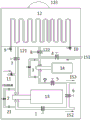
Fig. 1 is a schematic structural diagram of an automatic oil supply and discharge device according to an embodiment of the present invention.
Detailed Description
In order to make the technical problems, technical solutions and advantages to be solved more apparent, the following detailed description will be given with reference to the accompanying drawings and specific embodiments.
In order to solve the problem of complex structure of the oilfield steam injection boiler in the prior art, the embodiment of the invention provides an automatic oil supply and discharge device for automatically supplying oil, discharging oil and sweeping the oilfield steam injection boiler as shown in fig. 1, which comprises the following components: a discharge tank 12, a discharge pump 13, and a feed pump 14;
wherein the oil discharge tank 12 is provided with an oil discharge tank outlet 121 and an oil discharge tank inlet 122;
wherein the oil discharge pump 13 is provided with a first tee which is connected with the oil discharge tank outlet 121 through a pipeline provided with a seventh valve 7 and is connected with the oil storage tank outlet 152 through a first oil discharge pipeline provided with a first valve 1; wherein the oil feed pump is provided with a second tee which is connected with the inlet 122 of the oil discharge tank through a pipeline provided with an eighth valve 8 and is connected with the outlet 153 of the burner through a second oil discharge pipeline provided with a fifth valve 5; wherein the tank inlet 151 is connected to the dump tank inlet 122 through a line provided with a fourth valve 4 and an eighth valve 8; wherein the first oil discharging pipeline and the second oil discharging pipeline are communicated through a communication pipeline provided with a sixth valve 6, one end of the communication pipeline is communicated with the first oil discharging pipeline between the first valve 1 and the oil storage tank outlet 152, and the other end of the communication pipeline is communicated with the second oil discharging pipeline between the fifth valve 5 and the combustor outlet 153.
The device further comprises a line sweeping mechanism, wherein a line sweeping inlet of the line sweeping mechanism is respectively connected with an oil discharge pump 13 through an eleventh valve 11 and is connected with an oil discharge tank outlet 121 through the eleventh valve 11 and a seventh valve 7; the first tee joint is connected with a first sweeping bypass line in parallel, and a second valve 2 is arranged on the first sweeping bypass line; the second tee joint of the oil feed pump 14 is connected in parallel with a second sweeping bypass line, and a third valve 3 is arranged on the second sweeping bypass line.
Wherein, be equipped with the heating pipeline in the oil discharge tank 12, the heating pipeline both ends are equipped with ninth valve 9 and tenth valve 10.
Wherein, the top of the oil discharge tank 12 is provided with an oil discharge port 123.
Wherein, be equipped with explosion-proof control box in the device.
Meanwhile, the embodiment of the invention also provides a method for automatically supplying and discharging oil by the automatic oil supplying and discharging device, which comprises the following steps:
and (3) automatic oil unloading: closing the second valve 2, the sixth valve 6 and the eleventh valve 11, and conducting the first valve 1 and the seventh valve 7 to enable the stored oil of the oil discharge tank to flow into the oil storage tank through the first valve 1 and the seventh valve 7;
an automatic circulation oil supply step: closing the eighth valve 8, the third valve 3 and the sixth valve 6, and conducting the fourth valve 4 and the fifth valve 5 to ensure that the stored oil of the oil storage tank is conveyed to a burner outlet through the fourth valve 4 and the fifth valve 5 to supply oil to the burner;
and (3) oil unloading and line sweeping: closing the sixth valve 6 and the seventh valve 7, and conducting the eleventh valve 11, the second valve 2 and the first valve 1 so as to perform oil discharge and line sweeping;
oil supply and line sweeping steps: the seventh valve 7 and the eighth valve 8 are closed, and the eleventh valve 11, the second valve 2, the first valve 1, the sixth valve 6, the fifth valve 5, the third valve 3 and the fourth valve 4 are communicated so as to perform oil supply line sweeping.
The sixth valve 6 can simply and quickly realize the flow switching of oil supply and oil discharge.
Technological parameter requirements are as follows:
1. all valves are connected by adopting an electric valve and a flange 21.
2. All processes and pump body installation areas are designed into an integral detachable platform, namely, the separation operation of the processes and the oil discharge tank body can be realized in the maintenance process.
3. The oil supply flow adopts a DN40 hard flow, and the oil discharge flow adopts a DN65 hard flow.
4. All the entrances and exits are prefabricated with quick soft connecting tee joints.
5. The specific dimensions are length (2 m) x width (1 m) x height (0.8 m).
6. The two normally open valves of the ninth valve and the tenth oil tank are manual valves, and the rest valves are all automatic control valves.
The scheme provided by the embodiment of the invention has the following advantages:
1. in the field of movable steam injection industry, the integrated oil unloading and oil supplying functions are realized, and the integrated device is the most portable, simple and multifunctional integrated device in the current industry range.
2. The device aims to improve the flexibility and the maneuverability of the movable steam injection industry of the oil field, and has unique advantages in the aspects of reducing the labor intensity of workers, realizing intelligent operation, reducing safety risk points, improving the production efficiency and the like.
Aiming at the current situation of a fuel system of a special wet steam generator in the field of oil fields, the invention designs and develops a portable integrated automatic oil supply and discharge device of a steam injection station, and has the following innovation points:
firstly, the structure is ingenious, the functions are integrated, the occupied area is small, and the motor is flexible: the device is a skid-mounted automatic platform and comprises four automatic functional modules including 1 automatic oil discharge, 2 automatic oil supply and circulation, 3 automatic line sweeping and 4 emergency switching, and has the advantages of small three-dimensional space, ingenious and reasonable layout and 2m total occupied area 2 Simple, convenient and convenient to transport.
Secondly, the operation of one key is simple and reliable, and the labor intensity of workers is greatly reduced. The invention is characterized in that: 1, independently programming, designing logic and realizing PLC program, independently designing a touch screen interface, and realizing an automatic function. (2) The functions are integrated, the programs are automatically controlled, remote and on-site control conversion can be realized, the operation workload is reduced, and the operation of one key is simple and clear. (2) All processes are connected in a flange mode, so that disassembly and maintenance are convenient, maintenance difficulty is reduced, and flexibility of movable steam injection equipment is enhanced.
Thirdly, saving large capital investment: compared with the independent functions, the single steam injection station can reduce 1 oil discharge tank, 1 oil pump house, 1 oil feed pump and 40m of metal soft flow. The existing 12 steam injection devices of the steam injection team unit are used for calculation, and the fund can be saved by 316.8 ten thousand yuan.
Fourthly, reducing the safety risk: the explosion risk of the combustible gas in the closed space is avoided by outdoor installation; the risk of electric shock of personnel operation in unsafe states such as rain and snow; eliminating the risk of scalding of steam line sweeping personnel; the safety performance of the movable steam injection station is greatly improved.
While the foregoing is directed to the preferred embodiments of the present invention, it will be appreciated by those skilled in the art that various modifications and adaptations can be made without departing from the principles of the present invention, and such modifications and adaptations are intended to be comprehended within the scope of the present invention.
Claims (3)
1. An automated oil supply and discharge device, comprising: a discharge tank, a discharge pump, and a feed pump;
wherein the oil discharge tank is provided with an oil discharge tank outlet and an oil discharge tank inlet;
the oil discharge pump is provided with a first tee joint, and the first tee joint is connected with an oil discharge tank outlet through a pipeline provided with a seventh valve and is connected with an oil storage tank outlet through a first oil discharge pipeline provided with a first valve; the oil supply pump is provided with a second tee joint, and the second tee joint is connected with an inlet of the oil discharge tank through a pipeline provided with an eighth valve and is connected with an outlet of the burner through a second oil discharge pipeline provided with a fifth valve; wherein the inlet of the oil storage tank is connected with the inlet of the oil discharge tank through a pipeline provided with a fourth valve and an eighth valve; the first oil discharging pipeline and the second oil discharging pipeline are communicated through a communication pipeline provided with a sixth valve, one end of the communication pipeline is communicated with the first oil discharging pipeline between the first valve and the outlet of the oil storage tank, and the other end of the communication pipeline is communicated with the second oil discharging pipeline between the fifth valve and the outlet of the combustor;
the device also comprises a line sweeping mechanism, wherein a line sweeping inlet of the line sweeping mechanism is connected with an oil discharge pump through an eleventh valve and is connected with an outlet of the oil discharge tank through an eleventh valve and a seventh valve; the first tee joint is connected with a first sweeping bypass line in parallel, and a second valve is arranged on the first sweeping bypass line; the second tee joint of the oil supply pump is connected with a second sweeping bypass line in parallel, and a third valve is arranged on the second sweeping bypass line;
wherein the automated oil supply and discharge device is configured to perform at least one of the following:
and (3) automatic oil unloading: closing the second valve, the sixth valve and the eleventh valve, and conducting the first valve and the seventh valve to enable the stored oil of the oil discharge tank to flow into the oil storage tank through the first valve and the seventh valve;
an automatic circulation oil supply step: closing the eighth valve, the third valve and the sixth valve, and conducting the fourth valve and the fifth valve to enable the stored oil of the oil storage tank to be conveyed to a burner outlet through the fourth valve and the fifth valve so as to supply oil for the burner;
and (3) oil unloading and line sweeping: closing the sixth valve and the seventh valve, and conducting the eleventh valve, the second valve and the first valve to perform oil discharge and line sweeping;
oil supply and line sweeping steps: and closing the seventh valve and the eighth valve, and conducting the eleventh valve, the second valve, the first valve, the sixth valve, the fifth valve, the third valve and the fourth valve to perform oil supply scavenging.
2. The automated oil supply and discharge device according to claim 1, wherein a heating pipeline is arranged in the oil discharge tank, and a ninth valve and a tenth valve are arranged at two ends of the heating pipeline.
3. The automated oil supply and discharge device of claim 1, wherein the top of the oil discharge tank is provided with an oil discharge port.
Priority Applications (1)
| Application Number | Priority Date | Filing Date | Title |
|---|---|---|---|
| CN201710087311.XA CN106869883B (en) | 2017-02-17 | 2017-02-17 | Automatic oil supply and discharge device and method |
Applications Claiming Priority (1)
| Application Number | Priority Date | Filing Date | Title |
|---|---|---|---|
| CN201710087311.XA CN106869883B (en) | 2017-02-17 | 2017-02-17 | Automatic oil supply and discharge device and method |
Publications (2)
| Publication Number | Publication Date |
|---|---|
| CN106869883A CN106869883A (en) | 2017-06-20 |
| CN106869883B true CN106869883B (en) | 2023-05-26 |
Family
ID=59166106
Family Applications (1)
| Application Number | Title | Priority Date | Filing Date |
|---|---|---|---|
| CN201710087311.XA Active CN106869883B (en) | 2017-02-17 | 2017-02-17 | Automatic oil supply and discharge device and method |
Country Status (1)
| Country | Link |
|---|---|
| CN (1) | CN106869883B (en) |
Families Citing this family (2)
| Publication number | Priority date | Publication date | Assignee | Title |
|---|---|---|---|---|
| CN107572471B (en) * | 2017-08-08 | 2019-07-16 | 航天晨光股份有限公司 | Multi items oil plant pipeline tank service truck and its control method |
| CN114484280B (en) * | 2022-04-15 | 2022-06-10 | 中国石油化工股份有限公司胜利油田分公司 | Flow regulating device for liquid carbon dioxide distribution |
Citations (5)
| Publication number | Priority date | Publication date | Assignee | Title |
|---|---|---|---|---|
| GB640864A (en) * | 1948-09-16 | 1950-08-02 | Wallsend Slipway & Engineering | Oil supply control system for oil burning installations |
| JP2000291945A (en) * | 1999-04-07 | 2000-10-20 | Sanyo Electric Co Ltd | Oil pump device |
| CN201513161U (en) * | 2009-08-24 | 2010-06-23 | 李继清 | Device for thermal recovery and gas injection of petroleum |
| CN201561268U (en) * | 2009-10-27 | 2010-08-25 | 贵阳铝镁设计研究院 | Oil supplying and discharging system device of heavy oil depot |
| CN203905922U (en) * | 2014-06-04 | 2014-10-29 | 中国海洋石油总公司 | Double-fuel thermal recovery hybrid drive system |
Family Cites Families (6)
| Publication number | Priority date | Publication date | Assignee | Title |
|---|---|---|---|---|
| CA2864651C (en) * | 2012-02-22 | 2018-03-27 | Conocophillips Canada Resources Corp. | Sagd steam trap control |
| CN202613486U (en) * | 2012-03-19 | 2012-12-19 | 蒋平锁 | Gas energy storage type safe and energy-saving pressure-stabilizing boiler oil supply system |
| BR112015031556A2 (en) * | 2013-06-18 | 2017-07-25 | Shell Int Research | method for recovering oil and system |
| CN203628694U (en) * | 2013-10-12 | 2014-06-04 | 中国石油天然气股份有限公司 | Integrated oil storage and supply device |
| CN205877720U (en) * | 2016-01-14 | 2017-01-11 | 大唐韩城第二发电有限责任公司 | Fuel oil depot pipe -line system |
| CN206448801U (en) * | 2017-02-17 | 2017-08-29 | 中国石油化工股份有限公司 | Automation supplies Unloading Device |
-
2017
- 2017-02-17 CN CN201710087311.XA patent/CN106869883B/en active Active
Patent Citations (5)
| Publication number | Priority date | Publication date | Assignee | Title |
|---|---|---|---|---|
| GB640864A (en) * | 1948-09-16 | 1950-08-02 | Wallsend Slipway & Engineering | Oil supply control system for oil burning installations |
| JP2000291945A (en) * | 1999-04-07 | 2000-10-20 | Sanyo Electric Co Ltd | Oil pump device |
| CN201513161U (en) * | 2009-08-24 | 2010-06-23 | 李继清 | Device for thermal recovery and gas injection of petroleum |
| CN201561268U (en) * | 2009-10-27 | 2010-08-25 | 贵阳铝镁设计研究院 | Oil supplying and discharging system device of heavy oil depot |
| CN203905922U (en) * | 2014-06-04 | 2014-10-29 | 中国海洋石油总公司 | Double-fuel thermal recovery hybrid drive system |
Also Published As
| Publication number | Publication date |
|---|---|
| CN106869883A (en) | 2017-06-20 |
Similar Documents
| Publication | Publication Date | Title |
|---|---|---|
| CN106869883B (en) | Automatic oil supply and discharge device and method | |
| CN202229608U (en) | Exhaust fume waste heat recovery system of coal gangue brick factory | |
| CN203752307U (en) | Intelligentized steam curing system | |
| CN105840983A (en) | LNG skid-mounted fuel gas supply device | |
| CN201166460Y (en) | Instantaneously-heated type full-automatic hot water apparatus | |
| CN210032787U (en) | Main power house layout structure of gas and steam combined cycle generator set | |
| CN206448801U (en) | Automation supplies Unloading Device | |
| CN217503795U (en) | Emptying drainage structure for direct-buried hot water pipeline | |
| CN103851782B (en) | High efficiency water-bath skid-mounted type shale gas heating furnace and heating means | |
| CN104929580A (en) | Well flushing and wax removal vehicle and wax removal method thereof | |
| CN103912981B (en) | A kind of water tank heating system of aluminium section bar processing industry | |
| CN211595509U (en) | Coke oven flue gas blending process unit | |
| CN213645231U (en) | Cleaning device for sulfur-containing equipment with mixed heat source | |
| CN103174400A (en) | Anti-freezing heat insulation device for drilling machine | |
| CN210172121U (en) | Online automatic cleaning device for furnace tube of heating furnace | |
| CN204477685U (en) | The recycling residual heat gasification installation of liquid gas | |
| CN202347076U (en) | Device for utilizing residual heat generated through galvanization | |
| CN201652799U (en) | Afterheat recycling and heating device of heat carrier oil | |
| CN202381989U (en) | Skid-mounted oil conveying device | |
| CN205690681U (en) | A kind of modularity, the heat-conducting oil furnace heating system of sledge dressization | |
| CN105546846A (en) | Single-plate tubular double-circulation hidden-pipeline solar water heater | |
| CN205079452U (en) | Superconductive crude oil heating furnace | |
| CN112275739B (en) | Sulfur-related equipment cleaning device with mixed heat source | |
| CN205316439U (en) | Movable gas heating system | |
| CN213016299U (en) | Standard ground construction gas field gas gathering station and upper and lower ancient combined gas field gas gathering station |
Legal Events
| Date | Code | Title | Description |
|---|---|---|---|
| PB01 | Publication | ||
| PB01 | Publication | ||
| SE01 | Entry into force of request for substantive examination | ||
| SE01 | Entry into force of request for substantive examination | ||
| GR01 | Patent grant | ||
| GR01 | Patent grant |