CN106796355B - Numerical methods for free-form lens construction: area parametric free-form surface lens structure - Google Patents
Numerical methods for free-form lens construction: area parametric free-form surface lens structure Download PDFInfo
- Publication number
- CN106796355B CN106796355B CN201580041646.7A CN201580041646A CN106796355B CN 106796355 B CN106796355 B CN 106796355B CN 201580041646 A CN201580041646 A CN 201580041646A CN 106796355 B CN106796355 B CN 106796355B
- Authority
- CN
- China
- Prior art keywords
- source
- display
- area
- light
- regions
- Prior art date
- Legal status (The legal status is an assumption and is not a legal conclusion. Google has not performed a legal analysis and makes no representation as to the accuracy of the status listed.)
- Active
Links
Images


Classifications
-
- G—PHYSICS
- G03—PHOTOGRAPHY; CINEMATOGRAPHY; ANALOGOUS TECHNIQUES USING WAVES OTHER THAN OPTICAL WAVES; ELECTROGRAPHY; HOLOGRAPHY
- G03B—APPARATUS OR ARRANGEMENTS FOR TAKING PHOTOGRAPHS OR FOR PROJECTING OR VIEWING THEM; APPARATUS OR ARRANGEMENTS EMPLOYING ANALOGOUS TECHNIQUES USING WAVES OTHER THAN OPTICAL WAVES; ACCESSORIES THEREFOR
- G03B21/00—Projectors or projection-type viewers; Accessories therefor
-
- G—PHYSICS
- G02—OPTICS
- G02B—OPTICAL ELEMENTS, SYSTEMS OR APPARATUS
- G02B26/00—Optical devices or arrangements for the control of light using movable or deformable optical elements
- G02B26/06—Optical devices or arrangements for the control of light using movable or deformable optical elements for controlling the phase of light
-
- G—PHYSICS
- G02—OPTICS
- G02B—OPTICAL ELEMENTS, SYSTEMS OR APPARATUS
- G02B27/00—Optical systems or apparatus not provided for by any of the groups G02B1/00 - G02B26/00, G02B30/00
- G02B27/0012—Optical design, e.g. procedures, algorithms, optimisation routines
-
- G—PHYSICS
- G02—OPTICS
- G02B—OPTICAL ELEMENTS, SYSTEMS OR APPARATUS
- G02B3/00—Simple or compound lenses
- G02B3/02—Simple or compound lenses with non-spherical faces
-
- G—PHYSICS
- G02—OPTICS
- G02B—OPTICAL ELEMENTS, SYSTEMS OR APPARATUS
- G02B3/00—Simple or compound lenses
- G02B3/02—Simple or compound lenses with non-spherical faces
- G02B3/08—Simple or compound lenses with non-spherical faces with discontinuous faces, e.g. Fresnel lens
-
- G—PHYSICS
- G02—OPTICS
- G02F—OPTICAL DEVICES OR ARRANGEMENTS FOR THE CONTROL OF LIGHT BY MODIFICATION OF THE OPTICAL PROPERTIES OF THE MEDIA OF THE ELEMENTS INVOLVED THEREIN; NON-LINEAR OPTICS; FREQUENCY-CHANGING OF LIGHT; OPTICAL LOGIC ELEMENTS; OPTICAL ANALOGUE/DIGITAL CONVERTERS
- G02F1/00—Devices or arrangements for the control of the intensity, colour, phase, polarisation or direction of light arriving from an independent light source, e.g. switching, gating or modulating; Non-linear optics
- G02F1/01—Devices or arrangements for the control of the intensity, colour, phase, polarisation or direction of light arriving from an independent light source, e.g. switching, gating or modulating; Non-linear optics for the control of the intensity, phase, polarisation or colour
- G02F1/13—Devices or arrangements for the control of the intensity, colour, phase, polarisation or direction of light arriving from an independent light source, e.g. switching, gating or modulating; Non-linear optics for the control of the intensity, phase, polarisation or colour based on liquid crystals, e.g. single liquid crystal display cells
- G02F1/133—Constructional arrangements; Operation of liquid crystal cells; Circuit arrangements
- G02F1/13306—Circuit arrangements or driving methods for the control of single liquid crystal cells
-
- H—ELECTRICITY
- H04—ELECTRIC COMMUNICATION TECHNIQUE
- H04N—PICTORIAL COMMUNICATION, e.g. TELEVISION
- H04N9/00—Details of colour television systems
- H04N9/12—Picture reproducers
- H04N9/31—Projection devices for colour picture display, e.g. using electronic spatial light modulators [ESLM]
- H04N9/3102—Projection devices for colour picture display, e.g. using electronic spatial light modulators [ESLM] using two-dimensional electronic spatial light modulators
- H04N9/312—Driving therefor
- H04N9/3126—Driving therefor for spatial light modulators in series
-
- H—ELECTRICITY
- H04—ELECTRIC COMMUNICATION TECHNIQUE
- H04N—PICTORIAL COMMUNICATION, e.g. TELEVISION
- H04N9/00—Details of colour television systems
- H04N9/12—Picture reproducers
- H04N9/31—Projection devices for colour picture display, e.g. using electronic spatial light modulators [ESLM]
- H04N9/3141—Constructional details thereof
- H04N9/315—Modulator illumination systems
- H04N9/3155—Modulator illumination systems for controlling the light source
-
- H—ELECTRICITY
- H04—ELECTRIC COMMUNICATION TECHNIQUE
- H04N—PICTORIAL COMMUNICATION, e.g. TELEVISION
- H04N9/00—Details of colour television systems
- H04N9/12—Picture reproducers
- H04N9/31—Projection devices for colour picture display, e.g. using electronic spatial light modulators [ESLM]
- H04N9/3179—Video signal processing therefor
- H04N9/3182—Colour adjustment, e.g. white balance, shading or gamut
-
- G—PHYSICS
- G02—OPTICS
- G02B—OPTICAL ELEMENTS, SYSTEMS OR APPARATUS
- G02B26/00—Optical devices or arrangements for the control of light using movable or deformable optical elements
- G02B26/08—Optical devices or arrangements for the control of light using movable or deformable optical elements for controlling the direction of light
- G02B26/0816—Optical devices or arrangements for the control of light using movable or deformable optical elements for controlling the direction of light by means of one or more reflecting elements
Abstract
A free-form lens (e.g., a phase modulator, lens, or deformable mirror) may be fabricated to reproduce the light pattern specified by the image data. The source region on the free-form lens is mapped to the target region area on the image. The area of the source region is adjusted to vary the amount of light delivered to each target region. The adjustment of the source area may be achieved using L-BFGS optimization, preferably incorporating smoothness and curl regularization terms. Embodiments apply parallel processing to obtain control values for a free-form lens in real-time or near real-time. The apparatus may process the image data and display an image by controlling the dynamically variable free-form lens using the processed image data.
Description
Cross Reference to Related Applications
This application claims priority from U.S. application No. 62/031250 filed on 31/7 2014 and U.S. application No. 62/194728 filed on 20/7 2015. FOR purposes of the united states, this application claims the benefit of U.S. application No. 62/031250 entitled METHODS AND APPARATUS LIGHT STEERING use PHASE-modified IMAGING filed on 31/7/2014 AND U.S. application No. 62/194728 filed on 20/7/2015 entitled "organic materials FOR FREE-FORM lens system," both of which are incorporated herein by reference FOR all purposes, as filed 35 u.s.c. 119.
Technical Field
The present invention relates to projecting light using a free-form surface lens. In some embodiments, the free form lens comprises a spatial phase modulator. Embodiments provide a light projector, a method for projecting light, an assembly for a light projector, and a tangible medium containing machine-readable instructions for implementing the method.
Background
There are many applications where it is desirable to project a light pattern. These applications include displays (e.g., movie projectors, computer displays, televisions, advertising displays, such as billboards, virtual reality displays, etc.), as well as architectural lighting, automotive lighting (e.g., headlights, driving lights), and special effect lighting (e.g., theater stage lighting, concert lighting).
One technical problem is to provide a display capable of achieving a high luminance level. For example, high brightness levels may be used to project light patterns with high dynamic ranges and/or light patterns that are visible under various ambient lighting conditions. Achieving high brightness levels with many current display technologies is accompanied by undesirably high power consumption.
The primary motivation for using light steering in imaging systems is that peak brightness levels far above Full Screen White (FSW) can be achieved. This is made possible because the light taken from dark areas can be redistributed (diverted) to areas where higher brightness is required. Another consequence of diverting the light is that a deeper black level can also be reached. By extending the highlight and black levels in the image, a wider range of light levels ("increased contrast") can be displayed simultaneously.
The light may be diverted by the free-form lens. Determining the configuration of a free-form lens that will divert light to provide a desired light pattern is computationally difficult for all but very simple light patterns. Calculating the caustic is an area of research relating to how a refractive and/or reflective optical layer affects the light distribution.
Some methods of calculating caustic involve determining the placement of pre-specified discrete primitives such as planar patches, quadratic patches, or gaussian patches. Pre-specified primitive-based methods typically suffer from edge effects when primitives are not touched in a compatible manner.
Some alternative methods apply optimal transmission. Optimal delivery seeks a mapping from source to target distribution such that the user-specified cost function is minimized. Optimal transmission has been applied in areas such as operational research and grid processing: the optimal transfer formula is used to determine a mapping of the source intensity distribution at the lens plane to the target distribution at the image plane. This method can achieve high contrast and very good image quality, but has high computational cost. A typical image may require several hours of computation. Furthermore, the computation is difficult to parallelize.
There remains a need for a light projector that is capable of generating a desired light field. There is a particular need for a method of generating a desired light field that is computationally efficient and also provides a quality reproduction of the desired light field. Methods and apparatus for reproducing energy-efficient light fields are also desired.
Disclosure of Invention
The present invention has many aspects. Some aspects provide a light projector. Some aspects provide methods for generating a free-form optical device (which may include a spatial phase modulator) corresponding to a desired light field (which may include an image-which may be a video frame in some embodiments). Some aspects provide methods for processing data specifying a light field to derive a configuration for a corresponding free-form lens.
The invention also relates to a free-form lens construction. The free-form lens construction includes generating a desired light field by redistributing light from a source using a custom optical layer. Embodiments of the present invention provide a light projector including a free-form lens, a method for projecting a specified light field, and a method and apparatus for processing data defining a desired light pattern to produce a configuration for a free-form lens. In an exemplary embodiment, the optical layer comprises customized refractive and/or reflective elements or phase modulators. "calculating caustic" is a related art.
One exemplary aspect provides a method for controlling a phase modulator to display an image defined by image data. The method includes defining a plurality of non-overlapping source regions on the two-dimensional phase modulator and a plurality of display regions at the display plane, each source region having a boundary and a source area, and each source region being associated with a respective one of the display regions; each display area has a corresponding display area; assigning a target light intensity value to each of the plurality of display regions based on the image data; adjusting the configuration for the source regions, or the configuration for the display regions, or the configuration for both the source regions and the display regions, such that the ratio of the display area of the display region to the source area of the respective source region is proportional to the ratio of the source light intensity value of the source region to the target light intensity value assigned to the respective display region; generating a phase surface for each source area, the phase surface configured to redirect light incident on the source area onto a corresponding display area; and controlling the phase modulator to provide a phase surface to the source region and to illuminate the source region with incident light according to the source light intensity value.
Another exemplary aspect provides a method for generating a free-form lens configuration for displaying an image defined by image data. The method comprises the following steps: a model of a two-dimensional light source comprising a plurality of non-overlapping source regions is provided. Each source region has a boundary, a corresponding source light intensity value, and a source area. Each source region is associated with a respective display region of the display. Each display area has a target area. The method further distinguishes light distribution intensity values for each display based on the image data. The method sets a target source area for each source region such that a ratio of the target source area of the source region to a display area of the corresponding display region is proportional to a ratio of a light intensity value assigned to the corresponding display region to a source light intensity value of the source region. The method performs an optimization to determine a configuration of a boundary of the source region that optimally satisfies an objective function that quantifies a combined dispersion of a source area of the source region and a target source area corresponding to the source region. Based on the configuration of the source region boundaries after optimization, the method determines a normal vector for each source region and integrates the normal vectors to obtain a dephasing function that correlates phase to two-dimensional position. In the case where a phase modulator is used to provide a free form lens, a dephasing function may be applied to drive the phase modulator.
In some implementations, the source region includes non-overlapping source tiles defined by lines extending between the plurality of source vertices. Each source vertex has a position. In some implementations, the display tiles are defined by lines extending between a plurality of display vertices.
In some implementations, the source tile and the display tile are triangular. The optimization may determine an optimized location of the source vertex.
In some implementations, determining the normal vector for the source vertices is based on in-plane displacements of the source vertices relative to corresponding ones of the display vertices.
In some embodiments, the optimization includes applying a memory-limited Broyden-Fletcher-Goldfarb-Shanno algorithm. Some embodiments include performing optimization in a series of iterations at progressively finer scales (scales) such that in each iteration the number of source vertices and display vertices increases and the vertex positions of the immediately previous iteration are used as the starting configuration for the current iteration.
Other aspects and example embodiments are shown in the drawings and/or described in the following description.
Drawings
The drawings illustrate non-limiting exemplary embodiments of the invention.
Fig. 1 is a schematic diagram of an exemplary light projector. The input known light distribution (which may, but need not be, uniform) is first turned and then amplitude modulated. The amplitude modulation may be provided by a spatial light modulator. The embodiment of fig. 1 shows a projector using a transmissive element. Implementations are possible that apply other (e.g., reflective) light diverting elements and/or amplitude modulators.
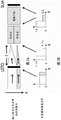
FIG. 2A and FIG. 2BFig. 2B schematically illustrates a free space implementation. The light falls on the spatial phase modulator with a known distribution (which may be uniform) (e.g., using HOLOEYE in some embodiments)TMLETO series phase only modulators). After phase modulation, the light continues to a Spatial Light Modulator (SLM). In one implementation, different areas on the spatial phase modulator may have different sizes, while areas on the SLM may have the same size. This enables the light intensity in each respective area of the SLM to be varied. The intensity distribution of each step in the light path is indicated in the figure. The spatial phase modulator and the SLM appear to be the same size in this figure, but this is not a requirement.
Fig. 3A and 3B show an exemplary implementation in which an integration rod is used. The diverted light from each region of the spatial phase modulator is focused to the center of an integration rod in the array of integration rods. An exemplary intensity profile for each step in the light path is indicated in the figure. This light is passed on to the SLM for final cleaning. The factor α is the result of focusing the light from the spatial phase modulator onto each integration rod, and should generally take into account power savings.
FIG. 4 is a diagram illustrating the flow of an exemplary offset and scaling SNS algorithm and its integration with a physical system. The target image is bisected and the required intensities in the two halves are 15 (left) and 5 (right) (arbitrary units of brightness) in this example. This allows us to divide the spatial phase modulator into two regions, where the area of the left hand side is 3 times the area of the right hand side. The light incident on the spatial phase modulator is then steered onto two equally sized areas on the SLM.
Fig. 5 shows an example of a tilted parabolic lens. The area of the spatial phase modulator may be configured to provide such a lens. The configuration of the lens can be controlled according to the position and size of the corresponding area on the SLM to which the lens light should be diverted.
Fig. 6A is a diagram (not to scale) illustrating the shape of a lens that can be implemented on a spatial phase modulator for a free space implementation. The size of the spatial phase modulator region may be determined by an SNS algorithm. The focal point of each region of the spatial phase modulator is indicated in the figure, to the right of the LETO-SLM assembly for region 1, and to the left of the LETO-SLM assembly for region 2.
Fig. 6B is a diagram (not to scale) illustrating the shape of a lens that can be implemented on a spatial phase modulator (e.g., LETO) for an integrating column implementation. The size of the area on the spatial light modulator may be determined by an SNS algorithm. The figures are not to scale.
Fig. 7A, 7B and 7C illustrate processing image data to determine desired brightness levels for different display regions. The 8x 16 block image of marlient (fig. 7A) shows the complete image with an 8x 16 area superimposed. Fig. 7B shows the first halving of the resulting average luminance level along the x-direction. Fig. 7C shows a second halving in the y-direction of each of the two halves calculated and shown in fig. 7B.
Fig. 8 shows the 8x 16 zone group of lenses calculated for the image of marlieta shown in fig. 7A. The right hand side is in mm.
Fig. 9 shows the lens calculated in fig. 8, wound as a multiple of the wavelength of light, λ (638 nm in this particular example). The units on the Right Hand Side (RHS) are multiples of λ. This mathematical operation mod (phase pattern, λ) is also called phase wrapping.
FIG. 10 is the calculated (ideal) output of the SNS derivative lens.
Fig. 11 shows how light from different areas or regions in the modulator plane (these may be referred to as source regions) is redistributed by scaling and shifting it towards corresponding areas or regions in the target plane (these may be referred to as display regions).
FIG. 12 is a diagram showing the modulator plane and the target image plane (each with a corresponding region) and the spot array used in the mathematical derivation. In some embodiments, the array of dots is configured such that each dot corresponds to a pixel of the spatial phase modulator in the modulator plane.
FIG. 13 is a diagram showing the optical path lengths between a modulator planar spot array and a corresponding target image planar spot array.
FIG. 14 is a graph showing optical path lengths between a modulator planar spot array and a corresponding target image planar spot array according to an embodiment: wherein the path length profile consists of the distance between a point in the source region and a point in a virtual parabola associated with the corresponding display region.
Fig. 15 is a diagram of an exemplary physical lens. Light enters along the optical axis, is transmitted without deflection after entering the rear lens surface, and is then refracted at the front lens surface, forming an angle θ with respect to the optical axis1. Transmission angle theta with respect to the optical axistAnd then given by snell's law.
Fig. 16A to 16C are a set of images showing the effect of padding. Images that are not properly padded often have boundary distortions due to the periodic assumption in the fourier transform. Mirror filling around the object results in a periodic image. This reduces the boundary distortion, but reduces the contrast.
Fig. 17A to 17D show the effect of changing the smoothness parameter on the image quality. Reducing the smoothness parameter may result in a significantly increased contrast but may also result in perceptible caustic artifacts.
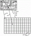
Fig. 18A to 18D show the effect of regularization. Fig. 18A and 18B are calculated point locations for area-based parameterization with and without curl regularization (with weight 1.0). Fig. 18C and 18D are the resulting output images. Incorporating curl regularization helps to reduce shear distortion and cause displacement.
Fig. 19A shows an exemplary mapping of dot locations of a marlieta image. The face and hair of Marilyn are mapped to almost the entire lens surface, greatly compressing the low intensity areas. Despite the high compression, most of the mapping quadrilateral is convex, which indicates a bijective parameterization. The local contrast in the resulting image is determined by the ratio of the areas of adjacent quadrilaterals. Fig. 19B is an enlarged portion of the eye of fig. 19A corresponding to myllier.
Fig. 20A-20C are images of einstein comparing the fourier paraxial (fig. 20A) and the area parameterization method (fig. 20B) for a free form lens. The area parametric image uses a gamma index of 3.0. Fig. 20C is a target image.
FIGS. 21A-21C are images comparing the Fourier paraxial (FIG. 21A) and areal parameterization (FIG. 21B) methods on a "fram-ref" image. Fig. 21C is the target.
Fig. 22A-22C are images comparing the fourier paraxial (fig. 22A) and area parametric (fig. 22B) methods on the lina images. Fig. 22C is a target.
Fig. 23A-23C are images comparing the fourier paraxial (fig. 23A) and area parameterization (fig. 23B) methods on a marlian image. Fig. 23C is a target.
Fig. 24A-24C are images comparing fourier paraxial (fig. 24A) and area parametric (fig. 24B) methods on "soldier" images. Fig. 24C is the target.
Fig. 25A to 25D show the effect of scaling of the area parameterization on the marlieta image shown in fig. 25E. Increasing the resolution reduces artifacts in highly stretched regions, indicating that spatially adaptive discretization may be beneficial.
Fig. 26A to 26D show the effect of curl regularization on the area parameterization result of the einstein image shown in fig. 26E. Increasing the weight of the curl regularization term results in more integratable displacements, which reduces stretch and shear artifacts, but reduces contrast. A typical value is 10.0.
Fig. 27A to 27D show the effect of changing the smoothness parameter on the area parameterization result of the marlieta image shown in fig. 27E. A low value of the smoothness parameter results in a higher contrast but more pronounced artifacts. High values of the smoothness parameter reduce contrast but help suppress artifacts. A typical value is 0.05.
Fig. 28A to 28D show the effect of changing the minimum area on the area parameterization result of the einstein image shown in fig. 28E. This parameter serves as the hard floor for the minimum area for which the optimization is directed. When set too low, a low quality image results, but with excellent contrast. When set too high, an effective light redistribution is prevented. A typical value is 0.05.
Fig. 29B and 29C are the lina image area parametric image of fig. 29A: scene contrast 106:1, peak brightness 2.8X FSW, and paraxial deblurring image: scene contrast: 67:1, peak luminance: 2:9 XFSW.
Fig. 30B and 30C are area parameterization images of the marlieta image of fig. 30A, respectively: scene contrast 582:1, peak brightness 11.92X FSW, and paraxial deblurring image: scene contrast: 173:1, peak luminance 10.0X FSW.
Fig. 31B and 31C are area parametric images of the "fram-ref" image shown in fig. 31A, respectively: scene contrast 377:1, peak brightness 6.2X FSW, and paraxial deblurring image: scene contrast 101:1, peak brightness 4X FSW.
Fig. 32B and 32C are area parameterization images of the einstein image shown in fig. 32A, respectively: scene contrast 759:1, peak brightness 13.15X FSW, and paraxial deblurred image: scene contrast 104:1, peak luminance 8.1X FSW.
Fig. 33A-33H are photographs comparing projections from a prototype projector (LETO) with area parameterization and paraxial deblurring methods with the same camera settings under broadband illumination.
Fig. 34A to 34D are photographs of projection from a prototype projector (LETO) under broadband illumination.
Figure 35B is a test capture of the "vengeant" image of figure 35A: scene contrast 1025:1, peak brightness 8.84 XFSW.
FIG. 36B is a trial capture of the "candle" image of FIG. 36A: scene contrast 697:1, peak brightness 9.85X FSW.
Fig. 37B is a trial capture of the "F1" image of fig. 37A: scene contrast 301:1, peak brightness 6.18X FSW.
FIG. 38B is a trial capture of the "cloud" image of FIG. 38A: scene contrast 697:1, peak brightness 7.42X FSW.
FIG. 39B is a trial capture of the "aerial" image of FIG. 39A: scene contrast 935:1, peak brightness 16.2X FSW.
Fig. 40 schematically shows the mapping between source and target regions.
Fig. 41 is a block diagram illustrating an apparatus according to an exemplary embodiment.
Fig. 42 is a block diagram illustrating a projector according to an exemplary embodiment.
Fig. 43A and 43B are flowcharts illustrating a method according to an example embodiment.
Detailed Description
In the following description, specific details are set forth in order to provide a more thorough understanding of the present invention. However, the invention may be practiced without these particulars. In other instances, well known elements have not been shown or described in detail to avoid unnecessarily obscuring the invention. The specification and drawings are, accordingly, to be regarded in an illustrative rather than a restrictive sense.
Various embodiments of a light projector and methods for configuring a free-form lens to project a desired light pattern are described herein. Some embodiments combine a light turning stage comprising a free form lens (provided by a spatial phase modulator in some embodiments) with a spatial amplitude modulation phase.
In some embodiments, the configuration for the light diverting stage is achieved by a method that includes associating a source region at the free-form lens with a display region where the light pattern is projected. The desired light intensity in the display area is adjusted by changing the relative area of the display area and its corresponding source area. The relative area of the source region and the display region may be changed by changing the area of the source region, changing the area of the display region, or changing the area of the source region and the area of the display region. The free-form lens may be configured such that each source region directs light onto a respective display region. In some embodiments, 90% or 95% or more of the light projected by each source region onto the target image plane falls within the corresponding display region. In some embodiments, the illumination intensity of the free-form lens is controlled based on an average or representative brightness of the desired light pattern. In some embodiments, the spatial amplitude modulation stage is provided at one or both of upstream and downstream of the free-form lens. The upstream SLM can change the brightness at the source region. The downstream SLM may further modulate the light illuminating the target image plane. In some embodiments, the downstream SLM may have a spatial resolution finer than the resolution of the display area.
The following description sets forth various ways of configuring a free-form lens in response to image data defining a desired light pattern. "Shift 'n' scale" (SNS) is a programmatically forward-only algorithm that, in some embodiments, enables light steering when used in conjunction with a phase-retarded imaging chip. In some embodiments, SNS can advantageously avoid or reduce edge effects. Some embodiments use a computational caustic method that involves determining an arrangement of predetermined discrete primitives (e.g., planar patches, quadratic patches, or gaussian patches) that can be used to configure a free-form lens.
Fig. 1 is a basic diagram illustrating a light projector that combines light turning of an incident light distribution with amplitude modulation to more efficiently form an image.
An example of such a display is manufactured by HoloEye Photonics AG, called LETO (1080 × 1920 pixels and a pixel pitch of about 6.4 microns.) the light reflected from LETO is incident on an amplitude modulator, in our case SonyTMLiquid crystal on silicon modulators (LCoS), which are non-limiting examples of Spatial Light Modulators (SLM). The image from the SLM is then relayed onto a projection screen.
Alternative implementations are possible, for example by reversing the order of the two modulators: the light is first amplitude modulated and then turned. Other possible implementations include a phase modulator of 1/2 that modulates only up to one wavelength of light (a so-called "pi-modulator"). Other possible amplitude modulators include Digital Light Projectors (DLPs) or Digital Micromirror Devices (DMDs), examples of which are available from texas instruments.
One implementation of the system sees the incident light distribution that is steered directly onto the SLM by LETO, as shown in fig. 2A and 2B. In other embodiments, a suitable kind of optical system may be provided between the spatial phase modulator and the SLM. Such an optical system may comprise, for example, an arrangement of one or more of lenses, mirrors, diffusers, free space, filters, and the like.
As shown in fig. 2A and 2B, steering is used to pre-modulate light incident on the SLM. This can be done by directing light from several areas of the spatial phase modulator through a lens onto corresponding areas on the SLM. The lens implemented in our case is a simple parabolic lens with focal lengths in the x and y directions depending on how much magnification is needed in both directions. Similarly, to move the distribution in the plane, a slope is applied to the lens action scheme in each region, one along the x-direction and one along the y-direction. These basic operations result in the so-called "Shift 'n' scale" (SNS).
An alternative implementation of the system employs equal sized regions on LETO illuminating different sized regions on the SLM. The derivation of the physical model is similar to that of the preferred implementation.
Another alternative implementation is illustrated by fig. 3A and 3B, which show a projector using an array of integrating posts between a spatial phase modulator and the SLM to homogenize the light. For example, homogenization may be advantageous to smooth irregularities in the laser beam distribution.
The outputs from different integrating columns may have different amplitudes, but their spatial distribution should be known or approximately known. The focal length of each region is approximately the same and is shown in fig. 3A and 3B. Small variations in the focal lengths of the different regions may ensure similar numerical apertures or propagation of light from each integration rod. The offset of each region will vary.
Moving and scaling algorithms
Many methods may be used to calculate the appropriate phase modulation image on the spatial phase modulator. In one approach, the spatial phase modulator is divided into regions, with different lenses defined to provide desired amounts of magnification and steering for those regions. In a sense, this is analogous to a programmable array having parabolic lenses, each lens shifting and scaling an area of light from a spatial phase modulator onto a corresponding area on the SLM on a frame-by-frame basis. The goal of the SNS algorithm is to provide fast, low resolution variations of the target image. If the resulting fast low resolution image does not have sufficient resolution for a particular application, an amplitude modulator may be used to generate the desired high resolution target image on the screen, but with minimal light loss since excessive amplitude modulation may be avoided.
The following two sections describe two example cases for splitting each of the spatial phase modulator and the target image plane (which may be on the SLM in some embodiments) into multiple regions. Alternative derivations using different sized regions on the spatial phase modulator and the SLM are also possible.
The method comprises the following steps: spatial phase modulator regions of different sizes; same size SLM area
The SNS algorithm analyzes the image to be displayed and effectively converts the intensity requirements of the target image into an area distribution (this is in a sense similar to the intermediate cut algorithm [ reference: http:// en. wikipedia. org/wiki/media _ cut ] SNS is a recursive multi-scale algorithm.
The determination of the "lighting requirements" during each halving step may be performed in different ways. For example, the most stringent requirement is that a maximum brightness level of each portion of the target image is achievable; this leaves the least amount of light available for redirection and is therefore the most conservative approach. Requiring only an average brightness per region will result in a loss of light level in each region and will necessarily reduce image quality, although this approach may be acceptable for some applications. Alternatively, it may be intended to reproduce some predetermined percentage of light for each region, e.g. by soft clip highlighting and/or black level (black level) beyond the available dynamic range of the respective region, which would require only a small amount of region-wise tone mapping.
In summary, the SNS approach uses a free-form lens such as a phase modulator that can be divided into many regions that can all be different in area depending on how much light is required to be delivered to a corresponding set of regions on the SLM. The size of the relative zones determines the amount of steering and magnification of each zone.
In one implementation, we determine the shape of each lens by calculating the required focal in-plane distance and in-plane offset for each region. A simple parabolic lens can be defined as follows:

wherein (f)x,i,fy,i) Is a focal length in the x-direction and the y-direction in the i-th area, and (m)x,i,my,i) Is the tilt of the lens in this region. Other implementations are possible. For example, processing the incident light distribution to reflect from the phase modulator at a specular angle (bounding off), the gradient surface may be obtained from where it is known that the light should be sent to the next modulator (e.g., SLM) or other target plane. The gradient map may be integrated to form a phase map for the spatial phase modulator.
Two exemplary ways of relaying light from the free-form lens to the SLM are described above. In the "free space approach", the focal length of each region will be determined by how much magnification is required between the source region in question and the corresponding display region. The correct magnification will be ensured by:
fx,i=D/(1-ax,i/bx,i) [2A]
where D is the distance between the free-form surface lens (e.g., spatial phase modulator) and the SLM, ax,iIs the x dimension of the source region on the spatial phase modulator and bx,iIs the x-dimension of the corresponding display area (e.g., on the SLM). These parameters are shown in fig. 6A and 6B.
In an alternative implementation, the light from the phase modulator is focused onto an array of integrating columns. In this case, the exact value of the focal length is less important. One can choose to focus all the light from each source region onto the input face of the array of integrating pillars, in other words f-D. As described in this section, small changes in the focal length of each region can be determined to ensure that similar light propagates at the output of the array of integrating rods.
The resulting per-zone lens may be similar to that shown in fig. 5.
Fig. 6A and 6B show cross-sections of two lenses of different sizes focusing light onto the SLM.
An example prototype implementation of the SNS decomposed the target image into 8 y regions by 16 x regions ("x" is the horizontal width of the image and "y" is the vertical height of the image). The image is repeatedly bisected (alternating in the direction of x, then y, then x.. times.) until the desired number of regions is obtained.
Fig. 7A to 7C show the repeated dichotomy of the input image of marilyn-menglu. The target image is 1080 × 1920 (high definition resolution), so each 8 × 16 unit is 135 × 120 pixels large.
In fig. 7B we see that the brightness requirement is 51 on the left hand side of the image and 48 on the right. Thus, the area of the Left Hand Side (LHS) will be 51/(51+48) of the total spatial phase modulator area, and the Right Hand Side (RHS) will be 48/(51+48) of the total spatial phase modulator area. Little reorientation is required for this deflection: only a small amount of additional light should be incident on the LHS. Due to the left-hand skew, the lens we form on the RHS should have a slight tilt or pitch towards the left.
In FIG. 7C, the LHS and RHS of the image are further bisected. The halving of the LHS results in a top 55 and a bottom 48. Thus, the upper left quadrant of the image will require more light than the lower left quadrant. The inclination of the bottom lens will be slight in the upward direction. This process and further bisection is repeated for the RHS, etc., until the image is segmented into 8x 16 sub-regions.
We now calculate the lens shape for each of these regions. Determining null according to equation 2AThe in-plane focal length (x and y) of each of the 8 × 16 regions of the inter-phase modulator, the tilt of each lens being determined by the central coordinates of the spatial phase modulator region on the SLM and the corresponding display region, and locating these points (x)1,y1)iReferred to as the ith region on the spatial phase modulator and these points (x)2,y2)iReferred to as the ith display area on the SLM. Offset m along x-directionx,iCalculated by the following formula:
mxi=-(x2,i-x1,i)/2fx,i[3A]
and a similar formula may be used for the slope in the y-direction. The lens shape of each of the 8 × 16 regions is calculated using the derived focal length and the tilt inserted in equation 1A.
An exemplary resulting lens array for a process of fully bisecting the 8x 16 region SNS is shown in fig. 8 and 9.
Fig. 10 shows the calculation result of reflected (bounding off) light from the lens image shown in fig. 9. In this example, the distance between the spatial phase modulator and the SLM is 170 mm.
The diverted light from the spatial phase modulator shown in fig. 10 can now be relayed onto the SLM. Note the unit on the right hand side of fig. 10. We see that by redirecting light using only 8x 16 regions, peak brightness levels can be achieved that exceed 45 times the brightness levels that can be provided by a uniformly illuminated imaging device. In some implementations, the peak brightness level exceeds 30 or 40 times the full screen white level (whitelevel) of the projector.
It is entirely feasible to divert the light such that a higher light level than required for the image in question can be achieved. In this case, a global reduction of the light source power may be achieved (e.g. by pulse width modulating it), or some light may be diverted into a light-dump (light-dump), or some light may be removed by focusing the light through a variable aperture.
The areas where the individual lenses meet (e.g., along the edges of the source regions) can be smoothed to eliminate sharp edges and possible unwanted artifacts. A simple low pass filter may be sufficient or the offset between adjacent regions may be minimized to achieve sufficient results.
The method 2 comprises the following steps: areas of LETO of the same size; different sizes of SLM areas.
For this discussion we assume that a uniform light distribution is incident on the spatial phase modulator plane and is redirected onto a target image plane at a distance from the modulator plane. Other incident light distributions may be used and considered. The SLM may optionally be placed in the object plane, but is not critical to the discussion immediately below.
The uniform light incident on the modulator plane is redirected onto a target image plane at a distance from the modulator plane. The modulator plane is divided into equal area areas (source regions), each of which is responsible for redirecting light onto a particular area (display region) of the target image plane (see fig. 11).
This approach is intended to make the portion of the optical power confined in each display area with respect to the entire target image the same as the portion confined in each source area with respect to the entire modulator.
The geometry of the display area is subject to the desired image plane illumination distribution and may be calculated using an algorithm such as a median cut algorithm. In the median cut example, a target image plane patch (segment) having one-quarter of the power of the entire image may be achieved by redirecting light from a modulator plane patch having one-quarter of the area of the entire modulator.
Phase modulator
The phase distribution established on the modulator is used to redirect the light to the target image plane in order to achieve the desired illumination distribution. The phase distribution may be calculated on a source region-by-source region basis, wherein light incident on a source region is redirected towards the corresponding display region by the phase distribution on that source region.
By defining both the source region in the modulator plane and the display region in the target plane as a network of points representing the respective position and orientation of each region, the calculation of the phase distribution for each source region can be made easier.
A typical choice of the number of points in the source region or modulator block is the number of pixels in the block that can be used for phase modulation. Each pair of corresponding source and display regions should have the same number of points evenly distributed across the respective regions so that a one-to-one point mapping can be made with respect to each pair of source and display regions.
Reorientation of
Given the point mapping associated with a particular pair of source regions and corresponding display regions, a phase distribution that will achieve the desired light redirection can be obtained in a number of different ways. The relationship between the phase distribution and the surface distribution is given by the Hyugens-Fresnel principle. The gradient of the phase profile determines the steering effect of the phase profile on the light. The phase profile is related to the surface profile of the physical lens by the refractive index of the medium (for the physical lens) and the control equation of the wave optics.
Since it is well known that the phase distribution can be related to the surface distribution of the optical path length, the following method is described in terms of path length rather than phase.
In one approach, the path length distribution of a modulator block consists of the physical distance of corresponding points in the block pair, see fig. 12.
Referring to fig. 12, we see that the optical path length between a modulator plane point map and a corresponding target image plane point map can be expressed as:

wherein M isiIs the coordinate of a particular point i in the modulator plane, TiContaining the coordinates of the corresponding point in the target image plane, and LiIs the length of the vector between the two points.
In other approaches, the center points of both the source regions and the corresponding display regions in a region pair are utilized. In one of these methods, the path length distribution consists of the distance separating a point in the source area (modulator block) from a point in a virtual plane located at the center of the display area (target plane block) and is orthogonal to the vector connecting the block centers. The point in the virtual plane for the distance corresponds to the position where the virtual plane intersects the line connecting the pair of patches (see fig. 13).
Referring to fig. 13, the optical path length between a modulator plane point map and a corresponding target image plane point map can be expressed as:

wherein the content of the first and second substances, is a vector connecting the blocks to the center, and
 is connected to a point M on the modulator plane blockiWith the center point T of the corresponding target plane blockcThe vector of (2). The points ● between the vectors represent commonly used symbols for vector dot products.
In another approach, the path length distribution consists of the distance separating a point in the source region (modulator block) from a point in a virtual paraboloid centered at the center of the corresponding display region (target plane block). The point in the virtual paraboloid for the distance may be located at a position where the line connecting the pair of blocks makes an angle of 90 degrees with the line connecting the virtual paraboloid point to the center of the target plane block (see fig. 14).
Referring to fig. 14, the optical path length between a modulator plane point map and a corresponding target image plane point map can be expressed as:

another aspect of the invention provides other example methods for determining a configuration of a configurable optical element (e.g., a refractive or phase modulating element) that causes a desired light field to be generated when light from a light source interacts with the configurable optical element. In some embodiments, the configurable optical element is dynamically reconfigurable. Such a method may be used to generate a light field corresponding to image data for high dynamic range projection. In some implementations, the image data includes video data, and displaying the frame of video data includes configuring the configurable optical element. In some alternative embodiments, the method is applied to define a configuration for a stationary physical lens (e.g., a configuration that may be applied to manufacture a lens by molding, machining, etc.) so as to provide a lens that will produce a desired image by interacting with light from a light source.
FIG. 15 shows an example arrangement of a generalized refractive optical element 12 interacting with light 14 from a light source 16. This arrangement represents a general projector. The arrangement is simplified because the element 12 has a flat rear surface 12A and light from the light source 16 is collimated and arrives perpendicular to the rear surface 12A. These conditions are not absolutely necessary, but they simplify the calculations and help provide a clear description of the algorithms that may be applied to determine the configuration of the element 12. For the case of optical systems in which the elements 12 are more complex, the algorithm suitable for generating the configuration of the elements 12 can be modified in a manner that is obvious to a person skilled in the art.
In the arrangement, light reaches the rear surface 12A traveling parallel to the optical axis 13, enters the element 12 at the rear surface 12A perpendicular to the optical axis 13, and is refracted after reaching the far surface 12B of the element 12, after which the light travels to the image surface. The transmission coefficient of the element 12 is nearly constant under the assumption that the thickness of the element 12 is negligible for most purposes ("thin lens assumption") and that the far surface 12B has a relatively shallow gradient.
When a physical lens surface is desired, the fresnel equation is used as an imaging model. These equations make the incident angle (θ)1&θ2) And the transmission angle and the refractive indices (n) of the two materials1&n2) And (4) associating. Incident angle theta1&θ2Measured with respect to the surface normal vector pointing from the material of the element 12 to the material surrounding the element 12. The incident angle and the transmission angle are related by the following equation:

where the light 14 is parallel to the optical axis 13, the normal N is thus oriented at θ with respect to the optical axis 131To (3). Then, the angle θ of the transmitted light with respect to the optical axis 13tIs thetat=θ2-θ1. This results in the following with respect to the desired angle θ1Is given to produce a given angle thetat。

For thin lenses aligned with the optical axis, a paraxial approximation may be used, which assumes sin θ ≈ θ and cos θ ≈ 1. With this assumption, the foregoing equation is simplified to:

where element 12 is replaced by a phase modulator, the equation is simplified as follows:
θ1=θt
these relationships determine how the incident ray is deflected by physical refraction at the lens surface or by the phase modulator. The purpose of a free-form lens is to use these relationships to determine a lens or phase curve that focuses light in the bright areas of the target image and defocuses light in the dark areas. The following sections discuss three methods that may be used to generate configurations of refractive and/or reflective and/or phase shifting elements that will generate a desired optical field upon illumination.
The method 3 comprises the following steps: paraxial blur correction formula
The paraxial blur correction formula couples the mapping of light from the light source to the target to the lens surface calculation by introducing paraxial assumptions to the image forming model, which greatly simplifies the problem to be solved.
The benefit of this approach is that a redistribution of light is guaranteed to produce an effective physical lens that does not rely on properly chosen discrete elements. The challenge is to solve the problem of poorly tuned dual-harmonic systems that tend to converge slowly using iterative methods, while being too dense to be effectively considered and solved, especially on highly parallel hardware such as GPUs or FPGAs.
This section introduces an alternative solver based on deconvolution. The tuning problem of the system is reduced by solving the problem as a deconvolution problem in fourier space, resulting in several orders of magnitude speedup. The following section introduces the basic paraxial model and then proposes an alternative formulation to solve in fourier space.
Image forming model
The images of points on the lens plane on the image plane located at the focal length f are respectively given by the following equation with respect to the physical lens phase curve.

v*=v+ftan(θ1)
These equations can be approximated with the following linear equations using the paraxial assumptions of sin θ ≈ θ and cos θ ≈ 1:

v*=v+fθ1
using paraxial approximation, angle θ1It can also be related to the gradient of the lens surface or phase curve p (v), giving:


by defining the nominal focal length f as f with respect to the phase surface or with respect to the physical lens The two formulas may be integrated into a single formula. Then from v → v*The determinant of the mapped jacobian J determines the magnification of an arbitrary point on the image plane.

The magnification is inversely proportional to the brightness on the image plane. Using the mapping v → v*And the intensity of the image at point v is associated with the formula:

this may then be linearized via a first order taylor series to obtain the non-linear image formation model in equation 1.

The image formation model can be expressed as an inverse problem, where the phase/lens surface is sought to reproduce the target image as close as possible. The resulting optimization problem is shown in equation 2.

In the formula (2), the reaction mixture is, is the image data (intensity of each point in the image); p (v) is the phase that varies according to the position v on the optical element; Ω is the area of the image; f is the nominal focal length (as defined above) and p (v)*Is the de-configuration of the optical element.
Minimizing the function (v) of equation (2)*Defining the lens or phase surface closest to the target image.
Solving algorithm
Due to the item The objective function provided by equation (2) is non-linear, which can be understood as the curvature of the target image I. To obtain a linear model, linearization of the bend may be introduced. Equation 2 can then be minimized in an iterative manner as shown in
 algorithm 1.

In each iteration of algorithm 1, after discretization into pixels, the linearized least squares problem is solved to minimize the sum of the residual squares Commercially available solvers and other solvers currently known in the art can be used to solve this problem.
 Algorithm 1 has been verified in simulation and physical prototype settings and produces good results. However, due to the square of the Laplacian The problem is poorly accommodated. For this reason, convergence using an iterative solver can be slow, while system density makes direct solver memory intensive.
The method 4 comprises the following steps: solutions in the Fourier domain
For periodic boundary conditions, the problem illustrated by equation (2) can be solved more efficiently in fourier space. One approach is to apply near-end operators. For any convex function F (x), the near-end operator proxγF(defined in equation 3) functions like a single step of trust domain optimization, where the value of x is sought that reduces F but does not deviate too far from the input argument q.

For least squares target The resulting near-end operator is shown below.
proxγF(q)=(γ+ATA)-1(γq+ATb)
With periodic boundary conditions and a being a circulant matrix, this can be a very efficient assignment in fourier space, as shown in equation 4.

Symbol Indicating forward and inverse Fourier transforms, indicating convex conjugate, and performing multiplication/division point by point parameter α > 0 as L on the curvature of the lens2A regularization parameter. Also tried L2Gradients penalize points, but are found to have an adverse effect on solution quality.
By definition And
And and q ═ pk(v) The problem can be solved iteratively in fourier space, resulting in algorithm 2.

By caching pk(v) Algorithm 2 may be implemented with one image warping, some vector operations, and one forward/inverse fourier transform per iteration. All of these operations can be highly parallelizable, whether by pixel or by scan line.
As shown, Algorithm 2 is a non-linear variant of the common near-end algorithm, the near-end method, which is used to assign x by the valuek+1←proxγF(xk) To minimizeBy calling prox recursivelyγFAnd (3) a fixed point algorithm of any convex F.
The difficulty with deblurring is to assign boundary conditions to the resulting lens/phase surface. It is desirable to map a rectangular lens to a rectangular image area, however, the periodic assumption when fourier is used may result in severe distortion near the boundary. Fig. 16A is an example image in which such distortion can be seen particularly along the central portion of the top and bottom image boundaries.
Results
The selection results of the physical lens made from the solution obtained using algorithm 2 are shown in fig. 20A, 21A, 22A, 23A and 24A. All lenses were calculated using a mirror fill-in gamma of 1000 and alpha of 2.0 at a resolution of 256 x 128 with a pixel pitch of 0.5mm, a focal length of 100 mm. Non-uniform rescaling results in slightly wrong focal length due to the non-power two-input size. All renderings were calculated at 130mm focal length using a blend + LuxRender with normal smoothing and cyclic subdivision. All images are gamma corrected for display with a gamma of 2.2. The border around each image shows the nominal full screen white value. The computation time per image is about 1 second, but there is a lot of code optimization space through parallelization, pipelining and migration to the GPU.
Algorithm 2 is able to reproduce relatively fine details. The redistribution of light is limited to about 1/4 the size of the screen, which can limit the contrast of some very high contrast images. Reducing the smoothness parameter a may improve this, but may introduce artifacts as seen by comparing fig. 17B, 17C and 17D.
The method 5 comprises the following steps: parameterized formula based on area
Another method of determining the mapping from source to target is area-based parameterization. Area-based parameterization methods are based on subdividing the lens or phase surface into patches or regions, which are then mapped onto the image plane. Some examples of this approach are described for Light Field Projectors in US61/893270(Light Field Projectors and Methods) and US62/031250(method and Apparatus for Light Steel Using Phase Modulated Imaging), both of which are incorporated herein by reference for all purposes.
The mapping from source to target may be embodied in a fresnel mapping in the case of a physical lens or as a gradient of a phase function in the case of phase modulation. Regardless of which image forming model is used, a method must be provided to determine what area on the lens plane should be mapped to a particular corresponding area in the image plane for optimal reproduction of the desired light pattern.
The light intensity in the area in the image plane can be controlled by changing the size of the corresponding area in the lens plane. Increasing the size of the corresponding area in the lens plane will increase the light intensity in the corresponding area of the image plane.
One way to establish a mapping between the lens plane and the image plane is to divide both the lens plane and the image plane into regions having boundaries and to establish a correspondence between regions of the lens plane and corresponding regions of the image plane. For example, fig. 40 schematically shows a lens plane 42 divided into a region 42A by a boundary 42B and an image plane 44 divided into a region 44A by a boundary 44B. As indicated by arrow 45, each region 44A of the image plane 44 corresponds to a respective region 42A of the lens plane 42.
At this point it is noted that the image plane and the lens plane are planar, for convenience but not mandatory. Typically, either or both of these surfaces may be curved. Furthermore, although this is the case in some embodiments, it is not mandatory that there be a 1:1 corresponds to the relationship. For example, in some embodiments, two or more regions 42A may correspond to one region 44A. Furthermore, it is not mandatory (although it is generally desirable) that the area 42A completely cover the lens plane 42.
Conveniently, the area 42A tiles the lens plane 42 and the area 44A tiles the image plane 44. The area 42A may be referred to as a "source area" and the area 44A may be referred to as a "target area" because the area 42A serves as a source of light illuminating the corresponding area 44A to replicate the target light pattern.
Conveniently, the boundary 42B is parameterized such that the size of the region 42A can be varied by varying the parameters that define the boundary 42B. In some embodiments, boundaries 42B and 44B comprise straight lines. In other embodiments, the boundaries 42B and/or 44B are curved.
One way to define the regions 42A and 44A is by triangulation with piecewise linear boundaries defining triangular regions. In such embodiments, the boundaries of the (parametric) triangle may be conveniently defined by the location of the triangle vertices. The triangle vertex displacement then corresponds to the gradient of the phase function, while the area inside the triangle corresponds to the area of constant curvature. With this area parameterization, the mapping maps a piecewise constant region on the lens plane to a piecewise constant region in the image plane.
An algorithm may be applied to find the boundary configuration of the boundary 42B which will result in a reproduction of the target light intensity in the area 44A in the image plane. For example, to determine the triangle vertex positions in the lens plane that will reproduce the target intensity within each triangle in the image plane. In case the lens plane is uniformly illuminated by the light source, the light intensity within the area of the image plane is given by the ratio of the area of the image plane to the area of the corresponding area in the lens plane. In the following example, a uniform illumination of the lens plane is assumed. However, the algorithm can be easily modified to account for non-uniformities in the illumination of the lens plane.
Exemplary embodiments
The input to the algorithm is the triangular mesh M ═ T, V. Where V is { V ═ V1,...,vnIs a set of vertices, where And T ═ T1,…,tmTherein of
 Is an integer index into V that defines an oriented triangle. The set of triangles defines a piecewise-linear discrete space
 Then tjHas a signed area of
Parameterized formulation of light redistribution seeks a set of vertex positions on the source surface So that
 Wherein IjIs the target intensity relative to the source intensity. The source intensity is assumed to be constant. A known non-constant light intensity from the light source can be easily adapted. In some embodiments, the source may be controlled to provide a non-constant light intensity that facilitates the display of a particular image. For example, the source may be controlled to provide an intensity distribution of stronger intensity in areas corresponding to greater intensity in the image and weaker intensity in areas corresponding to darker areas in the image.
Since the target intensity can have wide variations, this condition can be represented by the following objective function:

normalization by the target intensity ensures that the errors are weighted equally regardless of whether they correspond to bright or dark regions of the target image. The constant 0< <1 is used to regularize the problem in case the target intensity is exactly zero.
Energy conservation requirement (assuming no loss of light extracted from the lens plane to the image plane in any optical system). Therefore, it is desirable to adjust the total amount of light reaching the image plane to match the integrated target intensity. This may be achieved by pre-scaling the source intensity, e.g. by modulating the output of the light source, passing the light from the light source through an optical system comprising a variable aperture and/or a light modulator in the light path between the lens plane and the image planeAnd (4) a system.
Another physical constraint is the inability to reduce light. Thus, the negative active areas have no physical significance. The algorithm may include constraints This also requires that the resulting parameterization be bijective.
The vertex position V that results in the minimization of equation 5 yields a triangle that corresponds to the high target intensity level being enlarged and a triangle that corresponds to the low target intensity level being contracted. Little additional constraint on vertex position is required, except that the resulting triangle retains a positive area.
Attempting to directly optimize equation 5 may result in a poorly distributed vertex. Examples are shown in fig. 18A and 18C. The accuracy of the reproduction of a target light field (e.g., an image) can be significantly improved by introducing a curl regularization, which limits the solution space to one with a low curl. For example, fig. 18B and 18D are compared with fig. 18A and 18C.
The method 6 comprises the following steps: add curl and smoothness regularization to method 5
An exemplary curl regularization term is defined by equation 6, which is represented by each triangle of the computational mesh.

If the input is in the form of a mosaic rule net, the regularization term can be equivalently represented in the form of finite differences on the net rather than its component triangles.
Incorporating curl regularization results in lower distortion in the point map. Reducing curl in the point map also advantageously results in vertex displacements that can be better approximated by a smooth and continuous gradient of the lens surface. This is because the position of the apex is ultimately applied to define the gradient of the resulting lens or phase field, either explicitly in the case of phase or implicitly in the case of physical lens, by fresnel mapping.
In addition to curl regularization, some embodiments apply a smoothness regularization term. Equation 7 provides one example of a smoothness regularization term.

An exemplary optimization that combines both the rotation and smoothness regularization terms is shown in equation 8.

Numerical solution
In some embodiments, the curl regularization target in equation 8 is solved using the memory-constrained Broyden-Fletcher-golden farb-Shanno method (L-BFGS). Various implementations of L-BFGS are publicly available. These implementations include a libBFGS for the C programming language.
The L-BFGS uses the history of objective function gradient evaluations to establish an approximation to the inverse Hessian matrix to calculate the search direction. Once found, a second 1D optimization is performed along the search direction, looking for an approximate minimum. Advantageously, L-BFGS does not require re-evaluation of the Hessian for every value of V.
Nonnegative constraint A (V)*,tj) ≧ 0 prevents pre-computation of the system matrix or preconditioner. These constraints can be implemented using a logarithmic barrier method that introduces a penalty term for each triangle. An exemplary penalty term is shown in equation 9, which may be added to equation 8.

For example, the obstacle parameter may be scaled by a factor τ ∈ (0, 1)To the initial constraint A (V)*,tj) More accurate approximation of ≧ 0.

In many cases, the penalty may be omitted entirely (e.g., by setting 0) because the flipped triangle appears only in dark regions of the image by inverse scaling of the target intensity. This significantly improves the performance of the method, since multiple optimizations at different values can be replaced by a single optimization.
Scale space solution
While the curl regularization term helps to limit the solution to an integrable solution, since the objective function is a quartic function of the point map, the optimization may become stuck in the local minimum of the objective function in equation 8. To help improve this, optimization can be performed from coarse to fine in the scale space.
To help avoid trapping local minima, equation 8 is solved from coarse to fine in scale space. The pseudo code for this is shown in algorithm 4.

Assuming β ≠ 0, algorithm 4 ensures that the resulting parameterization is bijective. This is guaranteed because the triangles are upsampled by a factor of 2, so each subdivided triangle is completely contained within a single source triangle.
The multi-scale process allows the method to recover point maps with large displacements and low rotations. This results in an almost integratable point displacement field. This can be solved by the code when integrating the point shift to calculate the final lens surface or phase function.
Phase and lens surface generation
Once parameterization is complete, V-V may be displaced from the point*Generating a physical lens surface, wherein V represents a point on the target image plane, and V*Representing a point on the lens surface.These displacements determine the in-plane offset from a point on the lens surface to the image plane and hence the angle from the lens surface to the reflection point with respect to the optical axis.


These equations assume that the incident light is parallel to the optical axis and is measured relative to the optical axis in a plane parallel to a plane containing the optical axis and the direction of the outgoing rays.
Therefore, the normal line of the phase/lens surface is restricted to a plane parallel to a plane containing the optical axis and the outgoing ray direction, thereby forming θ with respect to the optical axis1The angle of (c). Integrating these normals, in the ideal case of no rotational displacement, yields the desired phase/lens surface. However, these vectors are only defined at the grid vertices. To accommodate this, integration may be performed using an unstructured grid (e.g., using a finite element method), or the normal may be resampled to the pixels of the phase/lens surface. The following exemplary implementations employ the latter approach. This allows flexibility in the integration method chosen.
To perform the resampling, the triangularly divided normal line can be rasterized onto an image representing the phase/lens surface. Phong interpolation can be used in this rasterization, which produces a normal field that can be accurately represented by segmented quadratic blobs.
If the resampled normal field is non-rotational, the lens/phase surface can be directly integrated by solving Poisson's equation. In practice, the resampled normal field is typically not curl free. This does not necessarily mean that the physical lens cannot reproduce the target normal field, only a continuous and smooth physical lens cannot. A lens that is not smooth and may even be discontinuous may reproduce a wider range of normal fields, possibly at the expense of visual artifacts near the discontinuity.
This naturally leads to the idea of performing integration using sparse optimization methods, seeking lens surfaces that satisfy the normal field except at kinks or discontinuous sparse sets. These methods are attractive because they automatically determine the topology of any non-smooth areas. This is different from using the designated blobs.
Some suitable sparse optimization methods are variations of the Least Absolute Deviation (LAD) problem, which are defined as follows:
p=argminp||Gp-N||1(10)
in equation 10, the matrix G represents a discrete gradient operator, p is the lens or phase surface to be recovered, and N is the target normal field. Variations of the LAD problem include the use of sparse norms, e.g., zero norms or non-convex but still continuous norms. After testing several options, the weighted LAD formula shown in equation 11 was selected for the prototype implementation.
p=argminp||WGp-WN||1(11)
W is a diagonal weighting matrix that favors certain non-contiguous locations over others. In the case of two rows in the gradient matrix per pixel in the resulting normal field, for W2i,2iAnd W2i+1,2i+1The weights of (a) may be set as: wherein a isiIs the mapped area of pixel i. The weighting function amplifies normal errors in dark regions, which promotes L1Optimized to place discontinuities in dark areas. Alternative weighting may take into account smoothness of the parameterization. Equation 11 may be solved using any number of numerical methods for sparse reconstruction, including the ADMM, Primal-Dual method, or linear programming formulation.
The area parameterization methods described herein may be parallelized on a GPU or FPGA or other suitable hardware, as these methods may be performed using a matrix-free algorithm that relies only on gradient evaluation and simple vector operations as inputs to the L-BFGS. The gradient calculation may be performed analytically in parallel for each pixel.
The methods described herein may be optimized in various ways to more quickly process and/or more accurately reproduce a target light pattern. For example, the L-BFGS can be concurrent across points and external products. Furthermore, adjusting line search parameters, parallelizing gradient calculations, and/or avoiding temporary storage units, as well as optimizing cache reads and removing temporary storage units in the L-gs algorithm may result in a significant speed increase compared to prototype systems used to generate the exemplary images shown in fig. 20B, 21B, 22B, 23B, 24B, 25B, 26B, 27B, 28B, and 29B.
By utilizing a multi-scale structure, faster methods with better parallelism can be achieved by performing area optimization using variants of the method parallelized on independent sets of vertices.
Undesirable artifacts in dark regions can be reduced by changing the normal integration process to work on a triangular mesh, rather than a resampled pixel mesh as described above. Further improvements can be achieved by optimizing the projection of each lens/modulator pixel onto the target image rather than each target image pixel onto the lens/modulator. This will reverse the effect of light and dark in the resulting optimization, possibly resulting in artifacts in the bright areas, but will avoid resampling. The disadvantage is that the resulting optimization may be less stable: when optimizing the projection onto the target image, small variations in the positioning of the modulator/lens pixels may result in very rapidly varying intensities within the target image.
Fig. 43A and 43B illustrate a non-limiting exemplary method 100. The method 100 combines both multi-scale processing performed by loop 101A and variable obstacle parameters implemented by loop 101B, with loop 101A repeating to increase the resolution level and loop 101B repeating to decrease the value of the obstacle parameter. An alternative method executes only one of the loop 101A and the loop 101B or does not execute the loop 101A and the loop 101B.
At block 102, the source region is initialized to provide an initial mapping 103. Block 102 may, for example, include assigning locations to vertices defining triangular or other shaped source regions. The number of source regions (and the number of corresponding display regions) may vary with the current scale/resolution.
The image data 105 is used to construct an objective function 109. In the illustrated embodiment, the resolution of image data 105 is set at block 106, and the current value is also set for the obstacle parameter at block 106. Block 106 may, for example, include downsampling or downsampling and filtering image data 105 to produce sized image data 107. Block 108 generates an objective function 109 using the sized image data. The objective function 109 is provided to block 110, and block 110 solves for the updated mapping 115. For example, block 110 may implement an L-BFGS solver algorithm. Block 110 may invoke one or more of the curl regularization term 112A, smoothness regularization term 112B, and area penalty 112C as described above.
In block 116, the obstacle parameter is updated (e.g., by scaling a current value of the obstacle parameter or selecting a next one of a plurality of reduced obstacle parameters). Block 118 checks to see if the updated barrier parameter is below the minimum barrier parameter value to be used. If the updated barrier parameter value is not below the minimum barrier parameter value to be used ("no" outcome of block 18), then the process loops back via loop 101B to repeat the next barrier parameter value. Blocks 116 and 118 may be reversed in order of appropriate changes to the testing of block 118.
In the event of a "yes" result at block 118 (indicating that all barrier parameter values for the current scale have been completed), block 120 checks to see if all scales have been completed (e.g., to see if the current resolution is full or maximum resolution). If so, processing continues in FIG. 43B. Otherwise block 122 increases the resolution of the map 115 and the objective function and process loops back through loop 101A to obtain an updated map at the new resolution.
Fig. 43B illustrates a continuation of the method 100 in which the map 115 is processed to drive the light projector. In block 124, the normals of the source regions defined by map 115 are resampled to produce resampled normals 117. In block 136, the resampled normals are integrated to produce the target phase surface 119. In block 128, the phase shift values in the phase surface 119 are adjusted modulo 2 π to generate phase modulator configuration data 129 such that they are within range of the phase modulator. In block 130, the phase modulator is driven according to the phase modulator configuration data 129. In block 132, the image is displayed.
The method 7 comprises the following steps: distribution problem formula
A variation of the above method produces a mapping from the illumination source to the target image using a distribution problem formula instead of or in addition to the formula exemplified by equation 8. Assignment problems and techniques for solving them are common in the field of operational research. For a set of source points s in equation 12iTarget point t of equal basejAn exemplary definition of the allocation problem is shown.

The matrix C (i, j) is a mapping w indicating a source point i to a target point ji,jA cost function of the cost of the unit. While constraints ensure that the source and target are fully mapped. In the standard linear distribution problem, the weight wi,jThe allowance is a score. The variant may require a binary wi,j。
If s isiIs the source position and tjIs the target location, then the common cost functions C (i, j) are manhattan and euclidean distances. In many cases, the cost function is sparse, meaning that only a subset of the possible allocations (i, j) are allowed, with infeasible matches implicitly allocating infinite costs.
The problem can be applied to caustic generation by generating source point and target point distributions in proportion to source and target brightness, and then calculating the optimal allocation between source and target by solving equation 12. These distributions then determine the exit angle from the source, and the configuration of the optical elements at the lens plane can then be obtained using the Snell mapping and normal integration methods discussed above. To solve equation 12, several methods can be used, including linear programming, or an auction algorithm or Hungarian algorithm in the discrete case of finding a 1:1 mapping.
The formation of caustic by equation 12 may be advantageous, for example, to minimize shear induced curl in the resulting normal field. These advantages may be traded off against the computational cost of solving equation 12 over the set of points in question. Equation 12 may require considerable computation to solve, particularly for large sets of points with non-sparse cost functions. Introducing a sparsity cost function in distance (manhattan or euclidean) limits the steering effect of the lens, effectively limiting the modifications to the local region.
In an exemplary method, an assignment problem formula is applied to improve the point mapping calculated by the area parameterization method described above to reduce the curl in the resulting normal map. This will also avoid having to solve the dense allocation problem, which is computationally expensive, but instead replaces it with a more quickly solved sparse problem.
Comparison of results
This section presents a comparison of paraxial deblurring and area parameterization methods. For paraxial deblurring, all lenses were calculated at 256 × 128 resolution using mirror filling with a pixel pitch of 0.5mm, a focal length of 100mm, and γ -1000 and a-2.0. Non-uniform rescaling results in slight errors in focal length due to the non-power two-input size. All renderings are calculated at 130mm focal length. The computation time per image is about 1 second, but with parallelization, pipelining and migration to the GPU, there is a large amount of code optimization space.
For the area parameterization, all lenses were calculated at 0.05, a 0.05, β 10.0 and 0. This selection of parameters prohibits all source regions (e.g., triangles) from being limited to the requirement of having a positive area. However, the resulting parameterization is typically bijective or near bijective. This can be seen in fig. 19A and 19B, where even if the dark areas of the image are heavily compressed (indicating that very little light is mapped to them), they remain convex. The tendency of the algorithm to produce bijective maps is at least partially caused by the normalization of the target intensities, which results in optimizing penalized relative errors rather than absolute errors in achieving the target magnification factor. The computation time is about 5 to 10 seconds per frame, but can be accelerated by a factor of 4 by working at the same resolution as the paraxial deblurring result, making the two computation times closer.
A comparison of paraxial deblurring and area parameterization methods is presented in fig. 20A-24C. Each image has a gray border indicating nominal incident illumination and a fine black border indicating no illumination. All images were gamma corrected with gamma 2.2, except for the einstein area parameterized image of fig. 20B, which used gamma 3.0. Images are rendered from the mesh file using a blend + LuxRender that is capable of normal smoothing and circular subdivision. The computation time per image is about 1 second, but with parallelization, pipelining and migration to the GPU, there is a large amount of code optimization space.
Overall, it can be seen that the paraxial deblurring formula reproduces fine details better than the area parameterization method: the paraxial deblurring method computes the results at about 1/8 scales compared to the 1/4 resolution of the area parameterization, and still displays finer details than those present in the area parameterization results. This difference can be attributed primarily to the fact that the area parameterization method can provide stronger steering than the paraxial deblurring method.
Both methods distort the input image to some extent. This is partly due to changing the size of the artifact and partly due to the lens becoming thick enough that the thin lens assumption does not apply well. Some lenses have a thickness of about 10% of their focal length. Most of the distortion can be corrected by slightly adjusting the distance of the lens from the image plane.
Test results
Several phase patterns are calculated for use on the prototype projector. The prototype projector used a coherent 532nm green laser source that was extended and passed to a 2 pi "LETO" phase modulator. The output of the phase modulator is then passed to a projection lens and onto a screen. Most patterns use the default parameters in the previous section. However, the "candle" image is used as 0.1. Images of "candle" (FIG. 36A), "Einstein" (FIG. 32A) and "revenge" (FIG. 35A) use L2And (4) integrating.
Comparative images between paraxial deblurring and area parameterization results captured using the same camera settings (ISO800, 0.01s, F20) are shown in fig. 29B-32C. The paraxial deblurring results have a relatively low contrast, which makes it difficult to see the structure of the image. The area parameterization results have better contrast but are sensitive to alignment within the projector optics and uniformity of illumination of the LETO. Slight misalignments in the projector may cause severe local distortion of the resulting image; several results show these distortions.
Fig. 33A-33H show similar comparisons for broadband illumination of LETO from low power white LEDs, with the output image focused on a white tile using the same phase pattern as in fig. 29B-29C. Artifacts introduced by the wrap-around in the phase pattern reduce somewhat at the expense of increased black levels and color differences. In this case, the area parameterization still goes beyond the paraxial deblurring approach.
A set of results from the area parameterization method using the camera settings highlighting contrast is shown in fig. 34A-34D. These image display area parameterization methods transfer a large portion of the light from dark to bright areas.
The techniques described herein may be implemented in various ways. Fig. 41 shows a device 50 according to an embodiment of the invention. The device 50 includes a processor 54, the processor 54 receiving image data 52 specifying a desired light field (which may be a picture, a light pattern, a video frame, etc.) and generating data specifying a lens or phase modulator configuration. The data 56 may be used to control a 3D printer 57A to produce printed physical lenses or a milling machine or other machining center 57B to produce physical lenses or molds for physical lenses or a data store 57C for later use. The data 56 may be provided to a light projector 57D that includes controllable lenses, mirrors/phase modulators, and the like.
Fig. 42 shows a light projector 60 that includes a controller 62 connected to receive data 56. Note that the functions of the controller 62 and processor 54 of the device 50 may be combined such that the light projector 60 receives and processes image data. In other embodiments, the light projector 60 may work with a preprocessor device that partially performs the functions of the device 50. The light projector 60 may then perform further steps to process the data.
The light projector 60 includes a light source 64 and a phase modulator 66. In some embodiments, the phase modulator 66 is replaced by a dynamically variable mirror or a dynamically variable lens. The phase modulator 66 is controlled by the display controller 62 to adjust the phase of light incident from the light source 64 on a pixel-by-pixel basis to display a desired image at an image 68. The image 68 may include a surface onto which light is projected, for example, from the front or back.
The light projector 60 may include one or more mechanisms to adjust the average brightness of the projected image to match the image data. The illustrated embodiment includes an optional control signal 64A that varies the light output of the light source 64. The illustrated embodiment also includes an optional global modulator 65, such as a variable aperture in the optical path between the light source 64 and the phase modulator 66. Global modulator 65 is operable to controllably attenuate light incident at phase modulator 66. In another exemplary embodiment, the phase modulator 66 is configured to direct some light away from the image 68 if directing all light received from the light source 64 to the image 68 would result in a higher than desired average image brightness.
The light projector 60 also includes an optional purge stage 67. The clean bench 67 may include a spatial light modulator, such as an LCD panel or digital mirror device, or the like, capable of adjusting the transmission of light to the image 66 on a pixel-by-pixel basis. The clean bench 67 may be used to adjust the average brightness of the projected image and may also be used to correct artifacts in the projected image.
Interpretation of terms
Throughout the specification and claims, unless the context clearly requires otherwise:
the terms "comprises," "comprising," and the like, are to be construed in an inclusive sense as opposed to an exclusive or exhaustive sense; that is, in the meaning of "including but not limited to";
"connected," "coupled," or any variant thereof, means any connection or coupling, either direct or indirect, between two or more elements; the coupling or connection between the elements may be physical, logical, or a combination thereof;
the use of "herein," "above," "below," and words of similar import, in describing the specification, is to be taken as a reference to the specification as a whole and not as a reference to any particular portion of the specification;
reference to a list of two or more items, "or" encompasses all of the following interpretations of the word: any item in the list, all items in the list, and any combination of items in the list;
the singular forms "a", "an" and "the" include any appropriate plural reference.
Words such as "vertical," "lateral," "horizontal," "upward," "downward," "forward," "rearward," "inward," "outward," "vertical," "lateral," "left," "right," "front," "rear," "top," "bottom," "over," "under," and the like, as used in this specification and in any appended claims (where present), are dependent upon the particular orientation of the device as described and illustrated. The subject matter described herein may assume a variety of alternative orientations. Accordingly, these directional terms are not strictly defined and should not be construed narrowly.
Embodiments of the invention may be implemented using specially designed hardware, configurable hardware, by a programmable data processor providing software (which may optionally include "firmware") capable of being executed on the data processor, by a special purpose computer or data processor that is specifically programmed, configured or constructed to perform one or more of the steps of the methods detailed herein, and/or by a combination of two or more of these steps. The software may comprise or consist of instructions for configuring a configurable logic device, such as an FPGA, to implement logic for performing the method. Examples of specifically designed hardware are: logic circuits, application specific integrated circuits ("ASIC"), large scale integrated circuits ("LSI"), very large scale integrated circuits ("VLSI"), etc. Examples of configurable hardware are: one or more programmable logic devices such as programmable array logic ("PAL"), programmable logic arrays ("PLA"), and field programmable gate arrays ("FPGA"). Examples of programmable data processors are: microprocessors, digital signal processors ("DSPs"), embedded processors, graphics processors, math coprocessors, general purpose computers, server computers, cloud computers, mainframe computers, computer workstations, and the like. For example, one or more data processors in a control circuit for a device may implement a method as described herein by executing software instructions in a program memory accessible to the processors.
The processing may be centralized or distributed. In the case of distributed processing, information, including software and/or data, may be centrally or distributively stored. Such information may be exchanged between different functional units over a communication network, such as a Local Area Network (LAN), a Wide Area Network (WAN) or the internet, wired or wireless data links, electromagnetic signals or other data communication channels.
For example, while processes or blocks are presented in a given order, alternative examples may perform routines having steps, or employ systems having blocks, in a different order, and some processes or blocks may be deleted, moved, added, subdivided, combined, and/or modified to provide alternative or subcombinations. Each of these processes or blocks may be implemented in a variety of different ways. Further, although processes or blocks are sometimes shown as being performed in series, these processes or blocks may instead be performed in parallel, or may be performed at different times.
Further, while elements are sometimes shown as being performed sequentially, they may be performed simultaneously or in a different order. It is therefore intended that the following appended claims be interpreted as including all such variations as fall within their intended scope.
The software and other modules may reside on a server, workstation, personal computer, tablet computer, image data encoder, image data decoder, video projector, video processor, video editor, audiovisual receiver, display (e.g., television), digital cinema projector, media player, multi-processor system, microprocessor-based or programmable consumer electronics, network PC, minicomputer, mainframe computer, and the like, as well as other devices suitable for the purposes described herein. One skilled in the relevant art will appreciate that aspects of the system may be practiced with other communications, data processing, or computer system configurations.
The present invention may also be provided as a program product. The program product may comprise any non-transitory medium carrying a set of computer readable instructions which, when executed by a data processor, cause the data processor to perform the method of the invention. The program product according to the invention may be in any of various forms. The program product may include, for example, non-transitory media such as magnetic data storage media including floppy disks, hard disk drives, optical data storage media including CD ROMs, DVDs, electronic data storage media including ROMs, flash RAMs, EPROMs, hardwired or preprogrammed chips (e.g., EEPROM semiconductor chips), nanotechnology memory, or the like. The computer readable signal on the program product may optionally be compressed or encrypted.
In some embodiments, the invention may be implemented in software. For greater clarity, "software" includes any instructions executed on a processor and may include, but is not limited to, firmware, resident software, microcode, etc. Both processing hardware and software may be centralized or distributed (or a combination thereof), in whole or in part, as is known to those skilled in the art. For example, software and other modules may be accessed via local memory, via a network, via a browser or other application in a distributed computing environment, or via other means suitable for the purposes described above.
Where a component (e.g., a software module, processor, assembly, device, circuit, etc.) is referred to above, unless otherwise indicated, reference to that component (including a reference to a "means") should be interpreted as including as equivalents of that component any component which performs the function of the described component (i.e., that is functionally equivalent), including components which are not structurally equivalent to the disclosed structure which performs the function in the herein illustrated exemplary implementations of the invention.
The following are non-limiting exemplary embodiments of the disclosed invention.
1. A method for controlling a phase modulator to display an image defined by image data, the method comprising:
defining a plurality of non-overlapping source regions on a two-dimensional phase modulator and a plurality of display regions at a display plane, each of the source regions having a boundary and a source area and each of the source regions being associated with a respective one of the display regions; each of the display regions has a corresponding display area;
assigning a target light intensity value to each of a plurality of the display regions based on the image data;
adjusting: an arrangement for the source region; or a configuration for the display area; or a configuration for both the source regions and the display regions such that the ratio of the display area of the display region to the source area of the respective source region is proportional to the ratio of the source light intensity value of the source region to the target light intensity value assigned to the respective display region;
generating a phase surface for each of the source areas, the phase surface configured to redirect light incident on the source area onto a respective display area; and
controlling the phase modulator to provide the phase surface to the source region and to illuminate the source region with incident light according to the source light intensity values.
2. The method of exemplary aspect 1 (or any other exemplary aspect herein) includes determining a target source area based on the image data, and adjusting the configuration of the source regions by performing an optimization to determine a configuration of a boundary of the source regions that best satisfies an objective function quantifying an integrated dispersion of the source area of the source regions and the target source area corresponding to the source regions.
3. The method of exemplary aspect 2 (or any other exemplary aspect herein), wherein generating the phase surface comprises: based on the configuration of the source region boundaries after the optimization, a normal vector for each of the source regions is determined and integrated to obtain a dephasing function that correlates the phase of the phase modulator with a two-dimensional position.
4. The method of exemplary aspect 2 (or any other exemplary aspect herein) wherein the source region includes non-overlapping source tiles defined by lines extending between a plurality of source vertices, each of the source vertices having a location, and wherein the display region includes non-overlapping display tiles defined by lines extending between a plurality of display vertices.
5. The method of example aspect 4 (or any other example aspect herein), wherein the source tile and the display tile are triangular.
6. The method of exemplary aspect 4 or 5 (or any other exemplary aspect herein), wherein the optimizing determines an optimized location of the source vertex.
7. The method of example aspect 1 (or any other example aspect herein) includes adjusting the configuration of the source region by performing a median slicing algorithm.
8. The method of exemplary aspect 1 (or any other exemplary aspect herein) or exemplary aspect 7, wherein generating the phase surface for each of the source areas includes generating a phase surface corresponding to a parabolic lens.
9. The method of exemplary aspect 8 (or any other exemplary aspect herein) includes defining the parabolic lens by a pair-wise focal length in orthogonal directions based on a difference in size of the source area and the corresponding display area along the orthogonal directions.
10. The method of exemplary aspect 9 (or any other exemplary aspect herein), wherein defining the parabolic lens includes specifying slopes in the two orthogonal directions, the slopes based on a displacement of the source region relative to the target region in the orthogonal directions.
11. The method of any one of exemplary aspects 1-10 (or any other exemplary aspect herein), wherein generating the phase surface comprises low-pass filtering.
12. The method of any one of exemplary aspects 1-11 (or any other exemplary aspect herein), wherein generating the phase surface comprises phase wrapping.
13. The method of any one of exemplary aspects 1-12 (or any other exemplary aspect herein), wherein illuminating the source region comprises controlling an output of a light source based on the image data.
14. The method of exemplary aspect 13 (or any other exemplary aspect herein) includes controlling an output of the light source based on an average brightness of the image.
15. The method of exemplary aspect 13 or 14 (or any other exemplary aspect herein), wherein controlling the output of the light source includes passing the output of the light source through a variable aperture and controlling a size of the variable aperture.
16. The method of any one of exemplary aspects 13-15 (or any other exemplary aspect herein), wherein controlling the output of the light source comprises varying an intensity of the light source.
17. The method of any one of exemplary aspects 1-16 (or any other exemplary aspect herein), wherein at least 95% of the light redirected by each of the source regions falls within a respective display region.
18. The method of any one of exemplary aspects 1-16 (or any other exemplary aspect herein), wherein the light redirected by each of the source regions substantially fills the respective display region.
19. The method of any one of exemplary aspects 1-18 (or any other exemplary aspect herein) comprising passing light from the phase modulator to the display area by way of an array of integrating posts.
20. The method of any one of exemplary aspects 1-19 (or any other exemplary aspect herein) comprising amplitude modulating light from the display region.
21. A method for controlling a phase modulator to display an image defined by image data, the method comprising:
providing a model of a two-dimensional light source comprising a plurality of non-overlapping source regions, each of said source regions having a boundary, a respective source light intensity value and a source area, and each of said source regions being associated with a respective display area of a display, each of said display areas having a respective display area;
differentiating light distribution intensity values to each of the displays based on the image data;
setting a target source area for each of said source regions such that a ratio of said target source area of said source region to a display area of a respective display region is proportional to a ratio of a light intensity value assigned to said respective display region to a source light intensity value of said source region;
performing an optimization to determine a configuration of a boundary of the source region that optimally satisfies an objective function quantifying an integrated dispersion of a source area of the source region and a target source area corresponding to the source region;
determining a normal vector for each of the source regions based on the configuration of the source region boundaries after the optimization;
the normal vector is integrated to obtain a dephasing function that relates the phase of the phase modulator to a two-dimensional position.
22. The method of example aspect 21 (or any other example aspect herein) wherein the source region includes non-overlapping source tiles defined by lines extending between a plurality of source vertices, each of the source vertices having a location, and wherein the display region includes non-overlapping display tiles defined by lines extending between a plurality of display vertices.
23. The method of example aspect 22 (or any other example aspect herein), wherein the source tile and the display tile are triangular.
24. The method of exemplary aspect 22 or 23 (or any other exemplary aspect herein), wherein the optimizing determines an optimized location of the source vertex.
25. The method of exemplary aspect 22 or 23 (or any other exemplary aspect herein), wherein the normal vector is located at the source vertex.
26. The method of any one of exemplary aspects 21-25 (or any other exemplary aspect herein), wherein determining the normal vector for the source vertex is based on an in-plane displacement of the source vertex relative to a respective one of the display vertices.
27. The method of exemplary aspect 22 (or any other exemplary aspect herein), wherein determining the normal vector includes determining an arctangent of a quotient of the displacement and an optical distance between the light source and the display.
28. The method according to any one of exemplary aspects 21 to 27 (or any other exemplary aspect herein) comprising determining the source light intensity values based on an average intensity of the image data.
29. The method according to exemplary aspect 28 (or any other exemplary aspect herein) comprises controlling an illumination source illuminating a phase modulator according to the source light intensity values.
30. The method according to any one of exemplary aspects 21-29 (or any other exemplary aspect herein), wherein the source light intensity values are equal.
31. The method of any one of exemplary aspects 21-30 (or any other exemplary aspect herein), wherein the optimizing includes accounting for a cost of curl for the solution phase function.
32. The method of exemplary aspect 31 (or any other exemplary aspect herein), wherein the cost for curl is determined according to:

33. the method of any one of exemplary aspects 21-32 (or any other exemplary aspect herein), wherein the optimizing includes accounting for a cost of non-smoothness for the solution phase function.
34. The method of exemplary aspect 33 (or any other exemplary aspect herein), wherein the cost for the non-smoothness of the solution phase function is determined according to:

35. the method of any one of exemplary aspects 21-34 (or any other exemplary aspect herein), wherein the source region is triangular.
36. The method of any one of exemplary aspects 21-35 (or any other exemplary aspect herein), wherein the display area is triangular.
37. The method of any one of exemplary aspects 21-36 (or any other exemplary aspect herein), wherein the optimizing comprises applying a memory-constrained Broyden-Fletcher-Goldfarb-Shanno algorithm.
38. The method of any one of exemplary aspects 21 to 37 (or any other exemplary aspect herein) comprising performing the optimization in a series of iterations at progressively finer scales, such that in each iteration the number of source vertices and display vertices increases, and the vertex positions of the immediately preceding iteration are used as a starting configuration for the current iteration.
39. The method of any one of exemplary aspects 21-38 (or any other exemplary aspect herein), wherein the integrating comprises resampling the normal vector to provide a resampled normal vector to each pixel of the phase modulator.
40. The method of exemplary aspect 39 (or any other exemplary aspect herein), wherein the resampling comprises performing Phong interpolation on the normal vector.
41. The method of any one of exemplary aspects 21-40 (or any other exemplary aspect herein), wherein the integrating comprises applying a sparse optimization method.
42. The method of exemplary aspect 41 (or any other exemplary aspect herein), wherein the sparse optimization method includes finding a solution phase function that minimizes a difference between a gradient of the solution phase function and the normal vector field.
43. The method of exemplary aspect 42 (or any other exemplary aspect herein), wherein the difference is a weighted difference that amplifies a normal error in a dark region of the image.
44. The method of any one of exemplary aspects 21-43 (or any other exemplary aspect herein) includes initializing the source region and the display region to a uniform triangulation.
45. The method of any one of exemplary aspects 21-44 (or any other exemplary aspect herein), comprising constraining the optimization to require all of the source regions to have a positive area.
46. The method of exemplary aspect 45 (or any other exemplary aspect herein) wherein constraining the optimization includes including a penalty term for each of the source regions in the objective function, wherein the penalty term is proportional to a source area of the source region and has a sign opposite to a term of the objective function that quantifies a combined dispersion of the source area of the source region and the target source area, and the method includes successively reducing a scaling parameter in the penalty term in each of a plurality of iterations, wherein the position of the vertex determined in one of the plurality of iterations is used as an initial condition for a next one of the plurality of iterations.
47. The method of any one of exemplary aspects 21 (or any other exemplary aspect herein) wherein the brightness within at least one of the display areas exceeds a full screen white level.
48. The method according to exemplary aspect 47 (or any other exemplary aspect herein), wherein the peak brightness exceeds 30 times the full screen white level.
49. The method of any one of exemplary aspects 21-48 (or any other exemplary aspect herein) includes amplitude modulating light incident on the phase modulator such that different ones of the source regions are illuminated by different intensities of light.
50. The method of any one of exemplary aspects 21-48 (or any other exemplary aspect herein) comprising uniformly illuminating the phase modulator.
51. A method for generating a desired light pattern, the method comprising:
establishing a corresponding relationship between a source region on the phase delay modulator and a corresponding display region in an image plane;
determining a desired optical power density for the display area from the image data;
adjusting one or both of the source region and the display region using the image data to achieve a power density distribution in the display region corresponding to the image data; and
the phase modulator is controlled to provide a phase shift pattern operable to redistribute light from each source region of the imaging chip to a respective one of the display regions by scaling and/or shifting light incident on the source regions of the phase modulator.
52. The method of exemplary aspect 51 (or any other exemplary aspect herein) includes configuring the source region to provide a lens having a focal length configured to provide the zooming.
53. The method of exemplary aspect 52 (or any other exemplary aspect herein), wherein the lens has different focal lengths in the x-direction and the y-direction.
54. The method of exemplary aspect 52 (or any other exemplary aspect herein) includes configuring the lens to include a slope configured to provide the offset.
55. The method according to exemplary aspect 54 (or any other exemplary aspect herein) includes controlling the slope in the x-direction and the y-direction, respectively.
56. The method of any one of exemplary aspects 51-55 (or any other exemplary aspect herein), wherein controlling the phase modulator comprises phase winding the phase shift pattern.
57. The method of any one of exemplary aspects 51-55 (or any other exemplary aspect herein), comprising varying an area of the source region.
58. The method of any one of exemplary aspects 51-57 (or any other exemplary aspect herein), comprising changing an area of the display region.
59. The method of any one of exemplary aspects 51-58 (or any other exemplary aspect herein), wherein the source region is rectangular.
60. The method of any one of exemplary aspects 51-59 (or any other exemplary aspect herein), wherein the display area is rectangular.
61. The method of any one of exemplary aspects 51-60 (or any other exemplary aspect herein), wherein the source region is triangular.
62. The method of any one of exemplary aspects 51-60 (or any other exemplary aspect herein), wherein the display area is triangular.
63. The method of any one of exemplary aspects 51-62 (or any other exemplary aspect herein), wherein a ratio of an area of the source region to a corresponding display region is at least equal to a ratio of an optical power density at the source region to a maximum optical power density specified in image data of the corresponding display region.
64. The method of any of exemplary aspects 51-62 (or any other exemplary aspect herein) comprising cropping the image data to produce cropped image data, wherein a ratio of an area of the source regions to a respective display region is at least equal to a ratio of an optical power density at the source regions to a maximum optical power density specified in the cropped image data for the respective display region.
65. The method of any one of exemplary aspects 51-62 (or any other exemplary aspect herein), wherein a ratio of an area of the source region to a corresponding display region is at least equal to a ratio of an optical power density at the source region to an average optical power density specified in image data for the corresponding display region.
66. The method of any one of exemplary aspects 51-65 (or any other exemplary aspect herein), wherein an optical power density within at least one of the display areas exceeds a full screen white level.
67. The method of exemplary aspect 66 (or any other exemplary aspect herein), wherein the brightness of at least one of the display areas exceeds 40 times the full screen white level.
68. The method of exemplary aspect 66 (or any other exemplary aspect herein), wherein the brightness of at least one of the display areas exceeds 30 times the full screen white level.
69. The method of any one of exemplary aspects 51-69 (or any other exemplary aspect herein) includes spatially amplitude modulating light incident on the phase modulator such that different ones of the source regions are illuminated by different intensities of light.
70. The method of any one of exemplary aspects 51-69 (or any other exemplary aspect herein) comprising uniformly illuminating the phase modulator.
71. The method of any one of exemplary aspects 51-70 (or any other exemplary aspect herein) comprising homogenizing light that has been redirected by the phase modulator.
72. The method of exemplary aspect 71 (or any other exemplary aspect herein), wherein homogenizing the light includes passing the light through an array of integrating rods.
73. The method of any one of exemplary aspects 51-73 (or any other exemplary aspect herein) includes calculating a phase shift pattern of the phase modulator from source region to source region.
74. The method of any one of exemplary aspects 51-73 (or any other exemplary aspect herein) includes establishing a first dot network in one of the source regions and a second dot network in a display region corresponding to the source region such that there is a 1-to-1 correspondence between dots of the first and second dot networks, determining path lengths corresponding to pairs of respective ones of the dots in the first and second dot networks, and setting a phase shift pattern in the source region according to the path lengths.
75. The method of exemplary aspect 74 (or any other exemplary aspect herein), wherein the path length extends perpendicular to a plane associated with the display area.
76. The method of exemplary aspect 74 (or any other exemplary aspect herein), wherein the path length extends perpendicular to a parabolic surface associated with the display area.
77. The method of any one of exemplary aspects 74-76 (or any other exemplary aspect herein) wherein the first dot network includes one dot for each pixel of the phase modulator within the source region.
78. The method of example aspect 51 (or any other example aspect herein), wherein adjusting one or both of the source regions and the display regions comprises performing an optimization algorithm to find boundaries of the source regions and/or respective display regions such that a ratio of areas of the source regions and respective display regions provides an optimal match to a target optical power density of the source regions.
79. The method of exemplary aspect 78 (or any other exemplary aspect herein), wherein the optimization algorithm includes a cost function term that penalizes curl in a field of points defining the source region.
80. The method of example aspect 78 or 79 (or any other example aspect herein), wherein the optimization algorithm includes a cost function term that penalizes a lack of smoothness of the phase-shift pattern.
81. A method for generating a light pattern defined by image data, the method comprising:
determining, for each of a plurality of light source regions, a size and a position of a respective display region;
controlling a phase modulator to simulate an array of lenses, each of the lenses corresponding to one of the light source regions, and configuring the plurality of lenses to have a focal length and a slope such that light incident on each of the plurality of lenses is redirected onto a respective display region.
82. The method of exemplary aspect 81 (or any other exemplary aspect herein) includes sizing the display regions such that a ratio of a source area of the source region to an area of the respective display region is proportional to a brightness of the source region to a brightness specified by image data of the respective display region.
83. The method of exemplary aspect 82 (or any other exemplary aspect herein), wherein determining the size and location of the display area includes processing the image data to iteratively:
dividing a portion of the image into a plurality of portions such that areas of the plurality of portions decrease as an average luminance specified by image data of the plurality of portions increases.
84. The method of exemplary aspect 83 (or any other exemplary aspect herein), wherein dividing the portion of the image into the plurality of portions includes dividing the portion of the image into two portions.
85. The method of exemplary aspect 83 or 84 (or any other exemplary aspect herein), wherein the portion is rectangular in outline.
86. The method of exemplary aspect 81 (or any other exemplary aspect herein), wherein determining the size and position of the display area includes performing a plurality of iterations of a median cut algorithm.
87. The method of any one of exemplary aspects 81-86 (or any other exemplary aspect herein), wherein controlling the phase modulator includes generating a phase surface corresponding to the lens array and low pass filtering the phase surface.
88. The method of any one of exemplary aspects 81-87 (or any other exemplary aspect herein), wherein configuring the lens comprises phase winding.
89. The method of any one of exemplary aspects 81-87 (or any other exemplary aspect herein) comprising controlling an output of the light source based on the image data.
90. The method of exemplary aspect 88 (or any other exemplary aspect herein) includes controlling an output of the light source based on an average brightness of the light pattern.
91. The method of exemplary aspect 88 or 89 (or any other exemplary aspect herein), wherein controlling the output of the light source includes passing the output of the light source through a variable aperture and controlling a size of the variable aperture.
92. The method of any one of exemplary aspects 89 to 91 (or any other exemplary aspect herein), wherein controlling the output of the light source comprises varying an intensity of the light source.
93. The method of any one of exemplary aspects 81-92 (or any other exemplary aspect herein), wherein the display areas are non-overlapping.
94. The method of any one of exemplary aspects 81-93 (or any other exemplary aspect herein), wherein at least 95% of the light redirected by each of the lenses falls within a respective display region.
95. The method of any one of exemplary aspects 81-94 (or any other exemplary aspect herein), wherein the light redirected by each of the lenses substantially fills a respective display area.
96. The method of any one of exemplary aspects 81-94 (or any other exemplary aspect herein) includes redirecting light onto the respective display area by way of an array of integrating posts.
97. The method of any one of exemplary aspects 81-96 (or any other exemplary aspect herein) comprising amplitude modulating light from the display region.
98. The method of exemplary aspect 97 (or any other exemplary aspect herein), wherein amplitude modulating the light includes controlling pixels of a spatial light modulator positioned to interact with the light.
99. A program product comprising a non-transitory data storage medium having computer-readable instructions recorded thereon, which, when executed by a data processor, cause the data processor to perform a method according to any one of exemplary aspects 1 to 98 (or any other exemplary aspect herein).
100. A program product comprising a non-transitory data storage medium having computer-readable instructions recorded thereon, which, when executed by a data processor, cause the data processor to configure a programmable logic device to perform a method according to any one of exemplary aspects 1 to 98 (or any other exemplary aspect herein).
101. A light projector, comprising:
a free-form surface lens illuminated by a light source; and
a controller connected to control a configuration of the freeform lens, the controller configured to:
associating pixels of the freeform lens with a plurality of source regions, each of the source regions corresponding to a display region;
adjusting relative sizes of the source regions and the corresponding display regions based on the image data; and
the pixels in each source region are controlled such that light incident on the source region illuminates the corresponding display region.
102. The projector according to exemplary aspect 101 (or any other exemplary aspect herein), wherein the free form lens includes a spatial phase modulator and the controller is connected to control phase delays provided by pixels of the spatial phase modulator.
103. The projector according to exemplary aspect 101 or 102 (or any other exemplary aspect herein), wherein the controller is configured to control an optical power of light from the light source incident on the free-form lens in response to the image data.
104. The projector according to exemplary aspect 103 (or any other exemplary aspect herein), wherein the controller is operable to control an amplitude and/or a width and/or a duty cycle of the power supplied to the light source.
105. The projector according to exemplary aspect 103 or 104 (or any other exemplary aspect herein), wherein the controller is connected to control an optical element operable to selectively direct a portion of light emitted by the light source to a recuperator.
106. The projector according to any one of exemplary aspects 103-105 (or any other exemplary aspect herein) comprising a variable aperture in an optical path between the light source and the free-form lens, wherein the controller is operable to control an opening of the aperture.
107. The projector according to any one of exemplary aspects 101-106 (or any other exemplary aspect herein) comprising an upstream spatial light modulator in an optical path between the light source and the free-form lens, wherein the controller is connected to control the upstream spatial light modulator to illuminate different ones of the source regions differently.
108. The projector according to any one of exemplary aspects 101-107 (or any other exemplary aspect herein) comprising a downstream spatial light modulator located in the optical path downstream of the free-form lens, the controller connected to control pixels of the downstream spatial light modulator to vary an amplitude of light in a light pattern produced by the projector at a target plane.
109. The projector according to exemplary aspect 108 (or any other exemplary aspect herein) wherein the downstream spatial light modulator has a resolution sufficient to provide a plurality of pixels operable to modulate light from each of the display regions.
110. The projector of any of exemplary aspects 101-109 (or any other exemplary aspect herein) comprising an array of integration rods in an optical path between the freeform lens and the display area, wherein the controller is operable to control the freeform lens to selectively divert different amounts of light into different ones of the integration rods.
111. The projector according to any one of exemplary aspects 101-110 (or any other exemplary aspect herein), wherein the controller comprises a programmed data processor.
112. The projector according to any one of exemplary aspects 101-111 (or any other exemplary aspect herein), wherein the controller includes: a configurable logic cell; and a data store comprising instructions for configuring the configurable logic cell.
113. The projector according to exemplary aspect 112 (or any other exemplary aspect herein), wherein the configurable logic unit comprises an FPGA.
114. An apparatus for controlling a freeform lens to display an image defined by image data, the apparatus comprising a processor configured by software instructions to:
defining a plurality of non-overlapping source regions on a two-dimensional phase modulator and a plurality of display regions at a display plane, each of the source regions having a boundary and a source area and each of the source regions being associated with a respective one of the display regions; each of the display regions has a corresponding display area;
assigning a target light intensity value to each of a plurality of the display regions based on the image data; and
determining: an arrangement for the source region; or a configuration for the display area; or a configuration for both the source regions and the display regions such that the ratio of the display area of the display region to the source area of the respective source region is proportional to the ratio of the source light intensity value of the source region to the target light intensity value assigned to the respective display region, and such that light incident on the source area is redirected onto the respective display area.
115. The apparatus according to exemplary aspect 114 (or any other exemplary aspect herein) comprises a drive circuit connectable to drive a free-form lens.
116. The apparatus of exemplary aspect 114 or 115 (or any other exemplary aspect herein), wherein the free-form lens includes a spatial phase modulator and the apparatus is configured to generate a phase surface for each of the source areas.
117. The apparatus according to any one of exemplary aspects 114-116 (or any other exemplary aspect herein) comprising an optimizer configured to perform an optimization to determine a configuration of a boundary of the source region that optimally satisfies an objective function quantifying a combined dispersion of a source area of the source region and a target source area corresponding to the source region.
118. The apparatus of exemplary aspect 117 (or any other exemplary aspect herein) wherein the optimizer includes a curl regularization term.
119. The apparatus of exemplary aspect 117 or 118 (or any other exemplary aspect herein), wherein the optimizer includes a smoothness regularizer.
120. An apparatus for controlling a phase modulator to display an image defined by image data, the apparatus comprising:
a controller configured with a model of a two-dimensional light source comprising a plurality of non-overlapping source regions, each said source region having a boundary, a respective source light intensity value and a source area, and each said source region being associated with a respective display region of a display, each said display region having a respective display area;
the controller is configured by software instructions to cause the controller to:
differentiating light distribution intensity values to each of the displays based on the image data;
setting a target source area for each of said source regions such that a ratio of said target source area of said source region to a display area of a respective display region is proportional to a ratio of a light intensity value assigned to said respective display region to a source light intensity value of said source region;
performing an optimization to determine a configuration of a boundary of the source region that optimally satisfies an objective function quantifying an integrated dispersion of a source area of the source region and a target source area corresponding to the source region;
determining a normal vector for each of the source regions based on the configuration of the source region boundaries after the optimization; and
the normal vector is integrated to obtain a dephasing function that relates the phase of the phase modulator to a two-dimensional position.
121. An apparatus for generating a desired light pattern, the apparatus comprising:
a light source;
a phase delay modulator illuminated by the light source;
a controller configured to:
establishing a corresponding relationship between a source region on the phase delay modulator and a corresponding display region in an image plane;
determining a desired optical power density for the display area from the image data;
adjusting one or both of the source region and the display region using the image data to achieve a power density distribution in the display region corresponding to the image data; and
the phase modulator is controlled to provide a phase shift pattern operable to redistribute light from each source region of the imaging chip to a respective one of the display regions by scaling and/or shifting light incident on the source regions of the phase modulator.
122. An apparatus for generating a light pattern defined by image data, the apparatus comprising:
a light source;
a phase modulator illuminated by the light source;
a controller configured to, for each of the plurality of light source regions:
determining the size and position of the corresponding display area; and
controlling the phase modulator to simulate an array of lenses, each of the lenses corresponding to one of the light source regions, and configuring a plurality of lenses to have a focal length and a slope such that light incident on each of the plurality of lenses is redirected onto a respective display region.
123. A controller for a light projector, the controller comprising a data processor and a data store, the data store comprising computer readable instructions for execution by the data processor, the instructions being configured to cause the data processor to perform the method according to any of the exemplary aspects 1 to 99.
124. A method for controlling a free-form lens to display an image defined by image data, the method comprising:
defining a plurality of non-overlapping source regions on the freeform lens and a plurality of display regions at a display plane, each of the source regions having a boundary and a source area and one source light intensity value, and each of the source regions being associated with a respective one of the display regions; each of the display regions has a corresponding display area;
assigning a target light intensity value to each of a plurality of the display regions based on the image data;
adjusting: an arrangement for the source region; or a configuration for the display area; or a configuration for both the source regions and the display regions such that the ratio of the display area of the display region to the source area of the respective source region is proportional to the ratio of the source light intensity value of the source region to the target light intensity value assigned to the respective display region;
generating a configuration for the freeform lens in each of the source areas, the configuration being arranged to redirect light incident on the source area onto a respective display area; and
controlling the free-form lens according to the configuration and illuminating the source region with incident light according to the source light intensity value.
125. Apparatus having any novel and inventive feature, combination of features, or sub-combination of features described herein.
126. Having any novel and inventive steps, acts, steps and
and/or combinations of acts or sub-combinations of steps and/or acts.
For purposes of illustration, specific examples of systems, methods, and devices are described herein. These are examples only. The techniques provided herein may be applied to systems other than the exemplary systems described above. Many variations, modifications, additions, omissions, and substitutions are possible in the practice of the present invention. The invention includes variations of the described embodiments that are obvious to a person skilled in the art, including variations obtained by: replacement of features, elements and/or actions with equivalent features, elements and/or actions; mixing and matching features, elements and/or acts from different embodiments; combining features, elements and/or acts from the embodiments described herein with features, elements and/or acts of other technologies; and/or omit combinations of features, elements, and/or acts from the described embodiments.
It is therefore intended that the following appended claims and claims hereafter introduced are interpreted to include all such modifications, permutations, additions, omissions and sub-combinations as may be reasonably inferred. The scope of the claims should not be limited by the preferred embodiments set forth in the examples, but should be given the broadest interpretation consistent with the description as a whole.
Claims (61)
1. A method for controlling a two-dimensional dynamically reconfigurable phase modulator to display an image defined by image data, the method comprising:
defining a plurality of non-overlapping source regions on a two-dimensional dynamically reconfigurable phase modulator and a plurality of display regions at a display plane, each of said source regions having a boundary and a source area and each of said source regions being associated with a respective one of said display regions and a source light intensity value; each of the display regions has a corresponding display area;
assigning a target light intensity value to each of a plurality of the display regions based on the image data;
adjusting: an arrangement for the source region; or a configuration for the display area; or a configuration for both the source regions and the display regions such that the ratio of the display area of the display region to the source area of the respective source region is proportional to the ratio of the source light intensity value of the source region to the target light intensity value assigned to the respective display region;
generating a phase surface for each of the source areas, the phase surface configured to redirect light incident on the source area onto a respective display area; and
controlling the phase modulator to provide the phase surface to the source region and to illuminate the source region with incident light according to the source light intensity values.
2. The method of claim 1, comprising determining a target source area based on the image data, and adjusting the configuration of the source region by performing an optimization to determine a configuration of a boundary of the source region that optimally satisfies an objective function that quantifies a combined dispersion of the source area of the source region and the target source area corresponding to the source region.
3. The method of claim 2, wherein generating the phase surface comprises: based on the configuration of the source region boundaries after the optimization, a normal vector for each of the source regions is determined and integrated to obtain a dephasing function that correlates the phase of the phase modulator with a two-dimensional position.
4. The method of claim 2, wherein the source region comprises non-overlapping source tiles defined by lines extending between a plurality of source vertices, each of the source vertices having a location, and wherein the display region comprises non-overlapping display tiles defined by lines extending between a plurality of display vertices.
5. The method of claim 4, wherein the source tile and the display tile are triangular.
6. The method of claim 4 or 5, wherein the optimization determines an optimized location of the source vertex.
7. The method of claim 1, comprising adjusting the configuration of the source region by performing a median slicing algorithm.
8. The method of claim 1 or claim 7, wherein generating the phase surface for each of the source areas comprises generating a phase surface corresponding to a parabolic lens.
9. The method of claim 8, comprising defining the parabolic lens by a pair of focal lengths in two orthogonal directions based on a difference in size of the source area and the corresponding display area along the two orthogonal directions.
10. The method of claim 9, wherein defining the parabolic lens comprises assigning slopes in the two orthogonal directions based on displacement of the source regions in the two orthogonal directions relative to the respective display regions.
11. The method of any of claims 1-5 and 7, wherein generating the phase surface comprises low pass filtering.
12. The method of any of claims 1-5 and 7, wherein generating the phase surface comprises phase wrapping.
13. The method of any of claims 1-5 and 7, wherein illuminating the source region comprises controlling an output of a light source based on the image data.
14. The method of claim 13, comprising controlling an output of the light source based on an average brightness of the image.
15. The method of claim 13, wherein controlling the output of the light source comprises passing the output of the light source through a variable aperture and controlling a size of the variable aperture.
16. The method of claim 13, wherein controlling the output of the light source comprises varying an intensity of the light source.
17. A method according to any one of claims 1 to 5 and 7 wherein at least 95% of the light redirected by each source region falls within the respective display region.
18. A method according to any one of claims 1 to 5 and 7 wherein the light redirected by each source region substantially fills the respective display region.
19. The method of any one of claims 1 to 5 and 7, comprising passing light from the phase modulator to the display area by way of an array of integrating posts.
20. The method of any one of claims 1 to 5 and 7, comprising amplitude modulating light from the display area.
21. A method for controlling a dynamically reconfigurable phase modulator to display an image defined by image data, the method comprising:
providing a model of a two-dimensional light source comprising a plurality of non-overlapping source regions, each of said source regions having a boundary, a respective source light intensity value and a source area, and each of said source regions being associated with a respective display area of a display, each of said display areas having a respective display area;
differentiating light distribution intensity values to each of the displays based on the image data;
setting a target source area for each of said source regions such that a ratio of said target source area of said source region to a display area of a respective display region is proportional to a ratio of a light intensity value assigned to said respective display region to a source light intensity value of said source region;
performing an optimization to determine a configuration of a boundary of the source region that optimally satisfies an objective function that quantifies a combined dispersion of a source area of the source region and a target source area corresponding to the source region;
determining a normal vector for each of the source regions based on the configuration of the source region boundaries after the optimization;
the normal vector is integrated to obtain a dephasing function that relates the phase of the phase modulator to a two-dimensional position.
22. The method of claim 21 wherein the source region comprises non-overlapping source tiles defined by lines extending between a plurality of source vertices, each of the source vertices having a location, and wherein the display region comprises non-overlapping display tiles defined by lines extending between a plurality of display vertices.
23. The method of claim 22, wherein the source tile and the display tile are triangular.
24. The method of claim 22 or 23, wherein the optimization determines an optimized location of the source vertex.
25. The method of claim 22 or 23, wherein the normal vector is located at the source vertex.
26. The method of claim 22 or 23, wherein determining the normal vector for the source vertex is based on an in-plane displacement of the source vertex relative to a respective one of the display vertices.
27. The method of claim 26, wherein determining the normal vector comprises determining an arctangent of a quotient of the in-plane displacement and an optical distance between the light source and the display.
28. A method according to any one of claims 21 to 23 comprising determining the source light intensity values based on an average intensity of the image data.
29. A method according to claim 28 comprising controlling an illumination source illuminating a phase modulator in dependence on the source light intensity values.
30. A method according to any one of claims 21 to 23 wherein the source light intensity values are equal.
31. The method of any one of claims 21 to 23, wherein the optimizing comprises accounting for a cost of curl for the solution phase function.
32. The method of claim 31, wherein the cost for curl is determined according to:

where V is the set of vertex positions on the source region, V is the set of vertex positions on the display region, m is the number of oriented triangles, tjTo define an integer exponent of the oriented triangle into V, x is the horizontal width of the image.
33. The method of any one of claims 21 to 23, wherein the optimizing comprises accounting for a cost of non-smoothness for the solution phase function.
34. The method of claim 33, wherein a cost for non-smoothness of the solution phase function is determined according to:

where V is the set of vertex positions on the source region, m is the number of oriented triangles, tjInteger exponent to define oriented triangle in set of vertex positions onto display areaAnd x is the horizontal width of the image.
35. A method according to any one of claims 21 to 23 wherein the source regions are triangular.
36. The method of any of claims 21-23, wherein the display area is triangular.
37. The method according to any one of claims 21 to 23, wherein the optimizing comprises applying a memory-limited Broyden-Fletcher-Goldfarb-Shanno algorithm.
38. A method according to any one of claims 21 to 23, comprising performing the optimization in a series of iterations at progressively finer scales, such that in each iteration the number of source vertices and display vertices increases, and the vertex positions of the immediately preceding iteration are used as a starting configuration for the current iteration.
39. The method of any of claims 21 to 23, wherein the integrating comprises resampling the normal vector to provide a resampled normal vector to each pixel of the phase modulator.
40. The method of claim 39, wherein the resampling comprises performing Phong interpolation on the normal vectors.
41. The method of any one of claims 21 to 23, wherein the integrating comprises applying a sparse optimization method.
42. A method as claimed in claim 41, wherein the sparse optimization method comprises finding a solution phase function that minimizes the difference between the gradient of the solution phase function and the field of normal vectors.
43. The method of claim 42, wherein the difference is a weighted difference that amplifies a normal error in a dark region of the image.
44. A method according to any one of claims 21 to 23, comprising initialising the source and display areas to a uniform triangulation.
45. A method according to claim 22 or 23, comprising constraining the optimisation to require all of the source regions to have a positive area.
46. The method of claim 45, wherein constraining the optimization comprises including a penalty term for each of the source regions in the objective function, wherein the penalty term is proportional to a source area of the source region and has an opposite sign to a term of the objective function, the objective function quantifies a combined dispersion of the source area and the target source area, and the method comprises successively reducing a proportional parameter in the penalty term in each of a plurality of iterations, wherein the position of the vertex determined in one of the plurality of iterations is used as an initial condition for a next one of the plurality of iterations.
47. The method of claim 21, wherein the brightness within at least one of the display areas exceeds a full screen white level.
48. The method of claim 47, wherein a peak brightness within at least one of the display areas exceeds 30 times a full screen white level.
49. A method according to any one of claims 21 to 23, comprising amplitude modulating light incident on the phase modulator such that different ones of the source regions are illuminated by light of different intensities.
50. A method according to any of claims 21 to 23, comprising uniformly illuminating the phase modulator.
51. A non-transitory data storage medium having computer readable instructions recorded thereon which, when executed by a data processor, cause the data processor to perform the method of any one of claims 1 to 50.
52. A non-transitory data storage medium having computer readable instructions recorded thereon which, when executed by a data processor, cause the data processor to configure a programmable logic device to perform the method of any one of claims 1 to 50.
53. An apparatus for controlling a two-dimensional dynamically reconfigurable phase modulator to display an image defined by image data, the apparatus comprising a processor configured by software instructions to:
defining a plurality of non-overlapping source regions on the two-dimensional dynamically reconfigurable phase modulator and a plurality of display regions at a display plane, each of the source regions having a boundary and a source area and each of the source regions being associated with a respective one of the display regions; each of the display regions has a corresponding display area;
assigning a target light intensity value to each of a plurality of the display regions based on the image data; and
determining: an arrangement for the source region; or a configuration for the display area; or a configuration for both the source regions and the display regions such that the ratio of the display area of the display region to the source area of the respective source region is proportional to the ratio of the source light intensity value of the source region to the target light intensity value assigned to the respective display region, and such that light incident on the source area is redirected onto the respective display area.
54. The apparatus of claim 53, comprising a drive circuit connectable to drive the two-dimensional dynamically reconfigurable phase modulator.
55. The apparatus of claim 53 or 54, wherein the two-dimensional dynamically reconfigurable phase modulator is a spatial phase modulator and the apparatus is configured to generate a phase surface for each of the source areas.
56. Apparatus according to any one of claims 53 to 54 comprising an optimizer configured to perform optimization to determine a configuration of the boundaries of the source regions that optimally satisfies an objective function that quantifies a combined dispersion of the source areas of the source regions and a target source area corresponding to the source regions.
57. The apparatus of claim 56, wherein the optimizer includes a curl regularization term.
58. The apparatus of claim 56, wherein the optimizer includes a smoothness regularization term.
59. An apparatus for controlling a dynamically reconfigurable phase modulator to display an image defined by image data, the apparatus comprising:
a controller configured with a model of a two-dimensional light source comprising a plurality of non-overlapping source regions, each said source region having a boundary, a respective source light intensity value and a source area, and each said source region being associated with a respective display region of a display, each said display region having a respective display area;
the controller is configured by software instructions to cause the controller to:
differentiating light distribution intensity values to each of the displays based on the image data;
setting a target source area for each of said source regions such that a ratio of said target source area of said source region to a display area of a respective display region is proportional to a ratio of a light intensity value assigned to said respective display region to a source light intensity value of said source region;
performing an optimization to determine a configuration of a boundary of the source region that optimally satisfies an objective function that quantifies a combined dispersion of a source area of the source region and a target source area corresponding to the source region;
determining a normal vector for each of the source regions based on the configuration of the source region boundaries after the optimization; and
the normal vector is integrated to obtain a dephasing function that relates the phase of the phase modulator to a two-dimensional position.
60. A controller for a light projector, the controller comprising a data processor and a data store, the data store comprising computer readable instructions for execution by the data processor, the instructions being configured to cause the data processor to perform the method of any of claims 1 to 50.
61. A method for controlling a dynamically reconfigurable free-form surface lens to display an image defined by image data, the method comprising:
defining a plurality of non-overlapping source regions on the freeform lens and a plurality of display regions at a display plane, each of the source regions having a boundary and a source area and one source light intensity value, and each of the source regions being associated with a respective one of the display regions; each of the display regions has a corresponding display area;
assigning a target light intensity value to each of a plurality of the display regions based on the image data;
adjusting: an arrangement for the source region; or a configuration for the display area; or a configuration for both the source regions and the display regions such that the ratio of the display area of the display region to the source area of the respective source region is proportional to the ratio of the source light intensity value of the source region to the target light intensity value assigned to the respective display region;
generating a configuration for the freeform lens in each of the source areas, the configuration being arranged to redirect light incident on the source area onto a respective display area; and
controlling the free-form lens according to the configuration and illuminating the source region with incident light according to the source light intensity value.
Applications Claiming Priority (5)
| Application Number | Priority Date | Filing Date | Title |
|---|---|---|---|
| US201462031250P | 2014-07-31 | 2014-07-31 | |
| US62/031,250 | 2014-07-31 | ||
| US201562194728P | 2015-07-20 | 2015-07-20 | |
| US62/194,728 | 2015-07-20 | ||
| PCT/CA2015/050730 WO2016015163A1 (en) | 2014-07-31 | 2015-07-31 | Numerical approaches for free-form lensing: area parameterization free-form lensing |
Publications (2)
| Publication Number | Publication Date |
|---|---|
| CN106796355A CN106796355A (en) | 2017-05-31 |
| CN106796355B true CN106796355B (en) | 2020-09-22 |
Family
ID=55216539
Family Applications (1)
| Application Number | Title | Priority Date | Filing Date |
|---|---|---|---|
| CN201580041646.7A Active CN106796355B (en) | 2014-07-31 | 2015-07-31 | Numerical methods for free-form lens construction: area parametric free-form surface lens structure |
Country Status (6)
| Country | Link |
|---|---|
| US (3) | US9936175B2 (en) |
| EP (2) | EP3879334B1 (en) |
| JP (3) | JP6757311B2 (en) |
| CN (1) | CN106796355B (en) |
| CA (1) | CA2916836C (en) |
| WO (1) | WO2016015163A1 (en) |
Families Citing this family (36)
| Publication number | Priority date | Publication date | Assignee | Title |
|---|---|---|---|---|
| PT2895188T (en) * | 2012-09-11 | 2018-02-08 | Coherus Biosciences Inc | Correctly folded etanercept in high purity and excellent yield |
| EP4009626A1 (en) * | 2013-10-20 | 2022-06-08 | Mtt Innovation Incorporated | Light field projectors and methods |
| EP3143763B8 (en) | 2014-05-15 | 2023-12-27 | MTT Innovation Incorporated | Light projector and method for displaying an image |
| CN112576950A (en) | 2014-08-14 | 2021-03-30 | Mtt创新公司 | Multi-laser light source |
| JP5811425B1 (en) * | 2014-09-02 | 2015-11-11 | 株式会社サンキコー | Periodic motion observation system |
| US10571696B2 (en) | 2014-12-26 | 2020-02-25 | Cy Vision Inc. | Near-to-eye display device |
| US10225529B2 (en) * | 2015-07-17 | 2019-03-05 | Nec Corporation | Projection device using a spatial modulation element, projection method, and program storage medium |
| WO2017156316A1 (en) | 2016-03-09 | 2017-09-14 | Reflexion Medical, Inc. | Fluence map generation methods for radiotherapy |
| EP3433672B1 (en) | 2016-03-25 | 2021-03-03 | CY Vision Inc. | Near-to-eye image display device delivering enhanced viewing experience |
| US10976705B2 (en) | 2016-07-28 | 2021-04-13 | Cy Vision Inc. | System and method for high-quality speckle-free phase-only computer-generated holographic image projection |
| US10491868B2 (en) * | 2016-08-05 | 2019-11-26 | Maxell, Ltd. | Projection video display apparatus |
| CN110830785B (en) | 2016-09-30 | 2021-09-03 | 杜比实验室特许公司 | Beam combining for highlight projection |
| CN117556839A (en) | 2016-12-28 | 2024-02-13 | 手持产品公司 | Illuminator for DPM scanner |
| JP6862255B2 (en) * | 2017-04-12 | 2021-04-21 | キヤノン株式会社 | Imaging device, imaging method and imaging program |
| JP7203758B2 (en) | 2017-05-12 | 2023-01-13 | エムティティ イノベーション インコーポレイテッド | Image projection system and image projection method for projecting light to form an image |
| EP4068764A3 (en) | 2017-09-25 | 2023-01-18 | Dolby Laboratories Licensing Corporation | System and method for displaying high quality images in a dual modulation projection system |
| US10488746B2 (en) | 2017-11-14 | 2019-11-26 | Dolby Laboratories Licensing Corporation | Aperture sharing for highlight projection |
| JP6750597B2 (en) * | 2017-12-01 | 2020-09-02 | カシオ計算機株式会社 | Wheel member |
| ES2902066T3 (en) | 2017-12-22 | 2022-03-24 | Dolby Laboratories Licensing Corp | Temporal modeling of phase modulators in multi-modulation projection |
| CN108876916B (en) * | 2018-06-04 | 2022-06-17 | 长江大学 | Braided river training image generation method and equipment |
| JP2020112674A (en) * | 2019-01-11 | 2020-07-27 | ソニーセミコンダクタソリューションズ株式会社 | Display device and method for adjusting display device |
| CN109752843B (en) * | 2019-03-06 | 2021-12-31 | 西安自由曲面光电科技有限公司 | Implementation method of free-form surface large-view-field low-distortion automobile rearview mirror |
| US10880528B1 (en) | 2019-10-31 | 2020-12-29 | Christie Digital Systems Usa, Inc. | Device, system and method for modulating light using a phase light modulator and a spatial light modulator |
| WO2021100510A1 (en) * | 2019-11-19 | 2021-05-27 | 株式会社小糸製作所 | Vehicle lamp system, light distribution control device, and light distribution control method |
| CN114930810B (en) * | 2019-12-11 | 2023-12-01 | 杜比实验室特许公司 | Projection system and method of driving the same |
| US20230176437A1 (en) * | 2020-04-15 | 2023-06-08 | Sony Group Corporation | Information processing device, information processing method, and information processing program |
| CN111413704B (en) * | 2020-04-16 | 2022-06-21 | 中国科学院云南天文台 | Laser ranging system comprising free-form surface lens beam shaping structure |
| CN114397755A (en) * | 2020-05-15 | 2022-04-26 | 华为技术有限公司 | Display device, method and vehicle |
| JPWO2021250993A1 (en) * | 2020-06-07 | 2021-12-16 | ||
| CN112180592B (en) * | 2020-10-14 | 2023-03-21 | 兰州大学 | Rapid optimization method for optical reverse design |
| CN112764213B (en) * | 2021-01-13 | 2022-07-29 | 师大瑞利光电科技(清远)有限公司 | Design and processing method of lamp tube reflector |
| CN112882224B (en) * | 2021-01-19 | 2021-12-14 | 中国工程物理研究院激光聚变研究中心 | Wavefront control method |
| CN113325575B (en) * | 2021-05-27 | 2023-08-15 | 长春理工大学 | Polarization aberration correction system of free-form surface optical system |
| WO2023002675A1 (en) * | 2021-07-21 | 2023-01-26 | ソニーグループ株式会社 | Lighting device |
| WO2023161237A1 (en) | 2022-02-22 | 2023-08-31 | Barco N.V. | Apparatus and methods for adjusting digital images |
| CN114994909B (en) * | 2022-05-13 | 2023-04-28 | 北京理工大学 | Off-axis reflection type imaging system design method based on free wave surface regulation holographic element |
Citations (2)
| Publication number | Priority date | Publication date | Assignee | Title |
|---|---|---|---|---|
| WO2010039440A1 (en) * | 2008-09-30 | 2010-04-08 | Dolby Laboratories Licensing Corporation | Systems and methods for applying adaptive gamma in image processing for high brightness and high dynamic range displays |
| WO2012145200A1 (en) * | 2011-04-19 | 2012-10-26 | Dolby Laboratories Licensing Corporation | High luminance projection displays and associated methods |
Family Cites Families (17)
| Publication number | Priority date | Publication date | Assignee | Title |
|---|---|---|---|---|
| US7172288B2 (en) * | 2003-07-31 | 2007-02-06 | Hewlett-Packard Development Company, L.P. | Display device including a spatial light modulator with plural image regions |
| JP2008015064A (en) * | 2006-07-04 | 2008-01-24 | Seiko Epson Corp | Illuminator and projector |
| KR20090094078A (en) * | 2006-10-26 | 2009-09-03 | 시리얼 테크놀로지즈 에스.에이. | Holographic display device |
| GB2445164A (en) * | 2006-12-21 | 2008-07-02 | Light Blue Optics Ltd | Holographic image display systems |
| DE102007025069B4 (en) * | 2007-05-21 | 2018-05-24 | Seereal Technologies S.A. | Holographic reconstruction system |
| GB2455523B (en) * | 2007-12-11 | 2010-02-03 | Light Blue Optics Ltd | Holographic image display systems |
| US20110122467A1 (en) * | 2008-07-21 | 2011-05-26 | Gerald Futterer | Light modulating device |
| GB0907297D0 (en) * | 2009-04-29 | 2009-06-10 | Light Blue Optics Ltd | Dynamic backlighting |
| WO2013130077A1 (en) * | 2012-02-29 | 2013-09-06 | Agilent Technologies, Inc. | Software defined microscope |
| CN103325129B (en) * | 2012-03-19 | 2016-04-20 | 无锡奥普顿光电子有限公司 | A kind of method utilizing phase modulator output image |
| US9726827B2 (en) * | 2012-11-01 | 2017-08-08 | Arizona Board Of Regents On Behalf Of The University Of Arizona | Reconfigurable diffractive optical switch and method for operating the same |
| US9453970B2 (en) * | 2012-11-01 | 2016-09-27 | The Arizona Board Of Regents On Behalf Of The University Of Arizona | Reconfigurable diffractive optical switch |
| JP6172431B2 (en) * | 2012-11-26 | 2017-08-02 | 株式会社リコー | Projection optical system |
| US9049413B2 (en) * | 2013-07-30 | 2015-06-02 | Dolby Laboratories Licensing Corporation | Multiple stage modulation projector display systems having efficient light utilization |
| EP4009626A1 (en) * | 2013-10-20 | 2022-06-08 | Mtt Innovation Incorporated | Light field projectors and methods |
| CN106662739B (en) * | 2014-06-03 | 2020-06-12 | Mtt创新公司 | High efficiency dynamic high contrast lens action for imaging, illumination and projection applications |
| DE102015110502A1 (en) * | 2014-07-04 | 2016-01-07 | Seereal Technologies S.A. | Projection apparatus and method for displaying a two-dimensional and / or three-dimensional scene or content |
-
2015
- 2015-07-31 CA CA2916836A patent/CA2916836C/en active Active
- 2015-07-31 EP EP20217558.4A patent/EP3879334B1/en active Active
- 2015-07-31 WO PCT/CA2015/050730 patent/WO2016015163A1/en active Application Filing
- 2015-07-31 JP JP2017502643A patent/JP6757311B2/en active Active
- 2015-07-31 EP EP15827729.3A patent/EP3175282B1/en active Active
- 2015-07-31 CN CN201580041646.7A patent/CN106796355B/en active Active
-
2017
- 2017-01-16 US US15/406,942 patent/US9936175B2/en active Active
-
2018
- 2018-02-08 US US15/891,973 patent/US10324361B2/en active Active
-
2019
- 2019-06-17 US US16/443,421 patent/US10942428B2/en active Active
-
2020
- 2020-08-28 JP JP2020145088A patent/JP7096298B2/en active Active
-
2022
- 2022-06-23 JP JP2022100879A patent/JP7460238B2/en active Active
Patent Citations (2)
| Publication number | Priority date | Publication date | Assignee | Title |
|---|---|---|---|---|
| WO2010039440A1 (en) * | 2008-09-30 | 2010-04-08 | Dolby Laboratories Licensing Corporation | Systems and methods for applying adaptive gamma in image processing for high brightness and high dynamic range displays |
| WO2012145200A1 (en) * | 2011-04-19 | 2012-10-26 | Dolby Laboratories Licensing Corporation | High luminance projection displays and associated methods |
Also Published As
| Publication number | Publication date |
|---|---|
| JP2022130532A (en) | 2022-09-06 |
| EP3879334B1 (en) | 2023-11-29 |
| JP7460238B2 (en) | 2024-04-02 |
| EP3879334A1 (en) | 2021-09-15 |
| JP7096298B2 (en) | 2022-07-05 |
| US20190369467A1 (en) | 2019-12-05 |
| US10942428B2 (en) | 2021-03-09 |
| JP2021039346A (en) | 2021-03-11 |
| EP3175282A4 (en) | 2018-03-21 |
| CN106796355A (en) | 2017-05-31 |
| CA2916836A1 (en) | 2016-01-31 |
| US20180176519A1 (en) | 2018-06-21 |
| JP2017532583A (en) | 2017-11-02 |
| EP3175282B1 (en) | 2021-06-09 |
| US20170127025A1 (en) | 2017-05-04 |
| JP6757311B2 (en) | 2020-09-16 |
| WO2016015163A1 (en) | 2016-02-04 |
| EP3175282A1 (en) | 2017-06-07 |
| US9936175B2 (en) | 2018-04-03 |
| CA2916836C (en) | 2017-12-12 |
| US10324361B2 (en) | 2019-06-18 |
Similar Documents
| Publication | Publication Date | Title |
|---|---|---|
| CN106796355B (en) | Numerical methods for free-form lens construction: area parametric free-form surface lens structure | |
| US11877102B2 (en) | Efficient, dynamic, high contrast lensing with applications to imaging, illumination and projection | |
| KR101874146B1 (en) | High resolution high contrast edge projection | |
| JP2014513817A5 (en) | ||
| US11079668B1 (en) | Reflective display |
Legal Events
| Date | Code | Title | Description |
|---|---|---|---|
| PB01 | Publication | ||
| PB01 | Publication | ||
| SE01 | Entry into force of request for substantive examination | ||
| SE01 | Entry into force of request for substantive examination | ||
| GR01 | Patent grant | ||
| GR01 | Patent grant |