CN106662294B - Light emitting device - Google Patents
Light emitting device Download PDFInfo
- Publication number
- CN106662294B CN106662294B CN201580044797.8A CN201580044797A CN106662294B CN 106662294 B CN106662294 B CN 106662294B CN 201580044797 A CN201580044797 A CN 201580044797A CN 106662294 B CN106662294 B CN 106662294B
- Authority
- CN
- China
- Prior art keywords
- light emitting
- emitting device
- light
- fluid
- vessel
- Prior art date
- Legal status (The legal status is an assumption and is not a legal conclusion. Google has not performed a legal analysis and makes no representation as to the accuracy of the status listed.)
- Active
Links
Images


Classifications
-
- F—MECHANICAL ENGINEERING; LIGHTING; HEATING; WEAPONS; BLASTING
- F21—LIGHTING
- F21V—FUNCTIONAL FEATURES OR DETAILS OF LIGHTING DEVICES OR SYSTEMS THEREOF; STRUCTURAL COMBINATIONS OF LIGHTING DEVICES WITH OTHER ARTICLES, NOT OTHERWISE PROVIDED FOR
- F21V5/00—Refractors for light sources
-
- F—MECHANICAL ENGINEERING; LIGHTING; HEATING; WEAPONS; BLASTING
- F21—LIGHTING
- F21V—FUNCTIONAL FEATURES OR DETAILS OF LIGHTING DEVICES OR SYSTEMS THEREOF; STRUCTURAL COMBINATIONS OF LIGHTING DEVICES WITH OTHER ARTICLES, NOT OTHERWISE PROVIDED FOR
- F21V29/00—Protecting lighting devices from thermal damage; Cooling or heating arrangements specially adapted for lighting devices or systems
- F21V29/50—Cooling arrangements
- F21V29/56—Cooling arrangements using liquid coolants
-
- F—MECHANICAL ENGINEERING; LIGHTING; HEATING; WEAPONS; BLASTING
- F21—LIGHTING
- F21K—NON-ELECTRIC LIGHT SOURCES USING LUMINESCENCE; LIGHT SOURCES USING ELECTROCHEMILUMINESCENCE; LIGHT SOURCES USING CHARGES OF COMBUSTIBLE MATERIAL; LIGHT SOURCES USING SEMICONDUCTOR DEVICES AS LIGHT-GENERATING ELEMENTS; LIGHT SOURCES NOT OTHERWISE PROVIDED FOR
- F21K9/00—Light sources using semiconductor devices as light-generating elements, e.g. using light-emitting diodes [LED] or lasers
-
- F—MECHANICAL ENGINEERING; LIGHTING; HEATING; WEAPONS; BLASTING
- F21—LIGHTING
- F21V—FUNCTIONAL FEATURES OR DETAILS OF LIGHTING DEVICES OR SYSTEMS THEREOF; STRUCTURAL COMBINATIONS OF LIGHTING DEVICES WITH OTHER ARTICLES, NOT OTHERWISE PROVIDED FOR
- F21V19/00—Fastening of light sources or lamp holders
- F21V19/001—Fastening of light sources or lamp holders the light sources being semiconductors devices, e.g. LEDs
-
- F—MECHANICAL ENGINEERING; LIGHTING; HEATING; WEAPONS; BLASTING
- F21—LIGHTING
- F21V—FUNCTIONAL FEATURES OR DETAILS OF LIGHTING DEVICES OR SYSTEMS THEREOF; STRUCTURAL COMBINATIONS OF LIGHTING DEVICES WITH OTHER ARTICLES, NOT OTHERWISE PROVIDED FOR
- F21V29/00—Protecting lighting devices from thermal damage; Cooling or heating arrangements specially adapted for lighting devices or systems
- F21V29/50—Cooling arrangements
- F21V29/502—Cooling arrangements characterised by the adaptation for cooling of specific components
- F21V29/503—Cooling arrangements characterised by the adaptation for cooling of specific components of light sources
-
- F—MECHANICAL ENGINEERING; LIGHTING; HEATING; WEAPONS; BLASTING
- F21—LIGHTING
- F21V—FUNCTIONAL FEATURES OR DETAILS OF LIGHTING DEVICES OR SYSTEMS THEREOF; STRUCTURAL COMBINATIONS OF LIGHTING DEVICES WITH OTHER ARTICLES, NOT OTHERWISE PROVIDED FOR
- F21V7/00—Reflectors for light sources
- F21V7/22—Reflectors for light sources characterised by materials, surface treatments or coatings, e.g. dichroic reflectors
-
- F—MECHANICAL ENGINEERING; LIGHTING; HEATING; WEAPONS; BLASTING
- F21—LIGHTING
- F21V—FUNCTIONAL FEATURES OR DETAILS OF LIGHTING DEVICES OR SYSTEMS THEREOF; STRUCTURAL COMBINATIONS OF LIGHTING DEVICES WITH OTHER ARTICLES, NOT OTHERWISE PROVIDED FOR
- F21V29/00—Protecting lighting devices from thermal damage; Cooling or heating arrangements specially adapted for lighting devices or systems
- F21V29/50—Cooling arrangements
- F21V29/502—Cooling arrangements characterised by the adaptation for cooling of specific components
- F21V29/506—Cooling arrangements characterised by the adaptation for cooling of specific components of globes, bowls or cover glasses
-
- F—MECHANICAL ENGINEERING; LIGHTING; HEATING; WEAPONS; BLASTING
- F21—LIGHTING
- F21Y—INDEXING SCHEME ASSOCIATED WITH SUBCLASSES F21K, F21L, F21S and F21V, RELATING TO THE FORM OR THE KIND OF THE LIGHT SOURCES OR OF THE COLOUR OF THE LIGHT EMITTED
- F21Y2115/00—Light-generating elements of semiconductor light sources
- F21Y2115/10—Light-emitting diodes [LED]
Abstract
The invention relates to a light emitting device comprising at least one light source (101) and a closed vessel, the vessel comprising a first region (105) and a second region (107) arranged opposite the first region (105), the closed vessel being filled with a heat conducting fluid (111) thermally coupled to an inner surface of the closed vessel, wherein the at least one light source (101) is arranged on an outer surface (115) of the first region of the closed vessel and is thermally coupled to the inner surface (113) of the closed vessel.
Description
Technical Field
The present invention relates to a light emitting device. The invention also relates to a heat sink for said light emitting device. The invention also relates to a lamp comprising said light emitting device. The invention also relates to a luminaire comprising said light emitting device or said lamp.
Background
The problem of thermal management of LEDs (light emitting diodes) in lamps is known in the art. LED-based solutions are less than 100% effective. The heat generated during operation often results in temperatures in the application that may degrade system effectiveness and may limit the life of the LEDs and/or other components. To transfer heat to the ambient environment, LED devices typically use a metal heat sink. In most LED applications, the heat sink and the light emitting area are two separate elements. The size of the heat sink is typically smaller than the entire lamp envelope, which limits heat transfer to the surroundings and thus thermal performance. In addition, heat sinks are typically heavy and expensive. Furthermore, heat sinks are typically not optically transparent.
US8454185B2 discloses a liquid cooled LED lamp having an outer envelope, an inner hollow vessel, and a plurality of LEDs on a substrate positioned in a space between the inner hollow vessel and the outer envelope. The space is filled with a heat conducting liquid for conducting heat generated by the LED to the outer lamp shade. A disadvantage of this lamp is that measures have to be taken in order to prevent that the electrical components will come into direct contact with the heat-conducting liquid. Furthermore, since LEDs present in the liquid may limit the circulation of the liquid in the space, heat transfer to the surroundings may be hindered. Furthermore, materials used in LEDs (e.g., luminescent materials such as inorganic phosphors, organic phosphors, or quantum dots) may be susceptible to degradation if these materials become in contact with a thermally conductive fluid.
The proposed system thus seems to suffer from thermal management problems that can only be (partially) solved at the expense of optical properties. Vice versa, thermal management is an issue when optimizing optical properties.
Disclosure of Invention
It is an object of the present invention to provide an alternative lighting device, which preferably further at least partly obviates one or more of the above-described drawbacks.
This object is achieved with a light emitting device according to the present invention, comprising at least one light source and an enclosed vessel comprising a first region and a second region arranged opposite to the first region, the vessel being filled with a heat conducting fluid thermally coupled to an inner surface of the enclosed vessel, wherein the at least one light source is arranged on an outer surface of the first region of the enclosed vessel and is thermally coupled to the inner surface of the enclosed vessel. The liquid in the container absorbs heat generated by the light source and acts as a heat spreader spreading the heat through the outer surface of the light emitting device. Due to buoyancy forces caused by a temperature difference within the fluid between a hotter spot in the fluid near the LEDs and a cooler spot in the fluid near the second region of the container, the fluid moves inside the container during operation of the light emitting device, which improves heat transfer to the surroundings. Thus, the container with the thermally conductive fluid will act as a heat sink to transfer the heat generated by the LEDs to the surrounding environment. Because the LEDs are not positioned inside the container, the movement of the fluid is not impeded by the LEDs. In this way, heat can be released to the surrounding environment via a larger surface area of the container. In addition, the LEDs are not in direct contact with the fluid, which reduces the risk with respect to short circuits. No additional metal heat sink, such as commonly used metal heat sinks, is required, which creates less risk of interaction with electromagnetic fields, X-rays or gamma radiation. Furthermore, the weight of the light emitting device can be reduced by a suitable choice of the fluid, since most fluids will have a lower density than the materials commonly used for heat sinks.
US2009/0154164a1 discloses an underwater light comprising a cylindrically shaped housing with two opposite ends open, a lens housed at one of the two opposite ends of the housing, and a heat sink base attached to the other of the two opposite ends of the housing. An interior space is defined between the housing, the heat sink base, and the lens. The light generating element is positioned in the interior space and thermally attached to the heat sink base. The lamp has two openings through which water flows into the inner space. The heat of the LED is mainly transferred to the heat sink base and further conducted to the plurality of fins.
DE541952 discloses a light emitting device for projection illumination, wherein a light source is embedded in a cooling bath with a reflective layer. Light is coupled into the cooling bath and reflected into the exit window. The cooling slot has an opening for providing a flow of cooling fluid through the cooling slot. The lamp is embedded in a cooling bath so that cooling is provided by a cooling fluid.
An embodiment of the invention is characterized in that: the thermally conductive fluid is optically transmissive (i.e., "optically transmissive fluid"), and at least a portion of the first and second regions are optically transmissive. At least a portion of the light generated by the light source may pass through the fluid before exiting the light emitting device via the second region. More degrees of freedom are obtained for the optical design of the light emitting device. The fluid and/or the container may be used for beam shaping of light or for producing other light effects.
An embodiment outside the scope of the invention is characterized in that: the container comprises as a first region a first circular plate and as a second region a second circular plate, the second circular plate being positioned at a distance of more than zero mm from the first cylindrical plate, and wherein a space between the first circular plate and the second circular plate is filled with a heat conducting fluid. In this embodiment, light can be generated from a larger area without the need for a more complex constructed metal heat sink.
The container comprises as a first region a first tubular vessel and as a second region a second tubular vessel surrounding the first tubular vessel at a distance greater than zero mm, and wherein a space between the first and second tubular vessels is filled with a heat conducting fluid. In this embodiment, the heat generated by the light source is transferred to the liquid and the locally heated fluid starts to move due to buoyancy. Finally, this causes an overall circulation of the fluid inside the cylindrical vessel without using mechanical actuation (so-called thermosiphon effect). The tubular shape of the first and second vessel increases the mechanical strength of the light emitting device, which may be important for light emitting devices with higher output power, which would require larger heat sinks.
Alternatively, the container comprises as a first region a first spherical vessel and as a second region a second spherical vessel enclosing the first spherical vessel at a distance greater than zero mm, and wherein the space between the first and second spherical vessels is filled with a heat conducting fluid. In this embodiment, a device is obtained that generates light substantially in all directions. In addition, such a device may be used in retrofit lamps. The spherical shape of the first and second vessel increases the mechanical strength of the light emitting device, which may be important for light emitting devices with higher output power, which would require larger heat sinks.
An embodiment of the invention is characterized in that: distance d1In the range of 1-10mm, more preferably in the range of 1-7mm, even more preferably in the range of 2-7mm, even more preferably in the range of between 2-4 mm. A thinner fluid layer results in a lower weight of the light emitting device. Furthermore, a thinner fluid layer may be beneficial for the optical properties of the light emitting device while still providing sufficient heat transport capability.
An embodiment of the invention is characterized in that: the thermally conductive optically transparent fluid has a viscosity of 5.108And 3.1010In the range of 6 · 10, more preferably9And 3.1010In the range of 1 · 10, even more preferably10And 3.1010Grashof (Grashof) numbers in the range between. The grashof number (Gr) is a known dimensionless number in fluid dynamics and heat transfer that approximates the ratio of buoyancy to viscous forces acting on a fluid. The fluid according to this embodiment will start to circulate easier and has better heat transport properties when heated during operation of the light emitting device. Generally, the higher the Grashof number of a fluid, the better its properties will be for use in the present invention.
An embodiment of the invention is characterized in that: the thermally conductive fluid is selected from the group consisting of silicone oil, methanol, ethanol, acetone, water, fluorinated aliphatic organic compounds, aromatic organic compounds, and dimethicone. These fluids are particularly suitable for creating a thermosiphon effect due to their large thermal expansion coefficient.
An embodiment of the invention is characterized in that: at least a portion of the container is made of one or more materials selected from the group consisting of a light-transmissive organic material, a glass material, a light-transmissive ceramic material, and a silicone material. These materials are light transmissive and allow sufficient freedom for the optical design of the light emitting device.
An embodiment of the invention is characterized in that: the light source comprises at least one Light Emitting Diode (LED). The heat in the LED is generated in a small amount so that it can be spread out over a large area. The LEDs may for example be present as a single LED, a plurality of LEDs, a strip with a plurality of LEDs or a chip-on-board LED source.
An embodiment of the invention is characterized in that: the light source comprises at least one array of light emitting diodes positioned substantially parallel to the longitudinal axis of the first tubular vessel, and wherein the distance between two adjacent light emitting diodes is in the range of 5-15mm, preferably in the range of 7-13mm, more preferably in the range of 8-12 mm. This embodiment allows the production of an elongated device that can be used, for example, as a TL replacement (retrofit) pipe. Bringing the LEDs close enough to each other will improve the uniformity of the light output by reducing the spots between the LEDs that may have a lower light output than spots closer to the LEDs.
An embodiment of the invention features at least three arrays of light emitting diodes positioned substantially parallel to a longitudinal axis of the first tubular vessel, and wherein the three arrays are positioned in an asymmetric distribution along a radius of the first tubular vessel. In this embodiment, a more uniform light output is obtained and is beneficial for good circulation of the liquid inside the vessel during operation of the device due to buoyancy.
An embodiment of the invention is characterized in that: at least a portion of the container and/or the thermally conductive fluid includes particles selected from the group consisting of scattering particles and inorganic luminescent particles, or a combination thereof. The use of scattering particles allows modifying the optical properties of the light emitting device and, for example, diffusing the light generated by the light emitting device. The use of inorganic luminescent particles allows to change the color of at least a part of the light emitted by the light source in order to generate white light of a desired color temperature or to produce colored light. Since the luminescent particles are not positioned directly on the light source itself, heating of the luminescent material due to the light source is prevented. Furthermore, heat generated by the luminescent particles during light conversion may be transferred to the liquid and/or the container.
An embodiment of the invention is characterized in that: the container comprises one or more optical elements for directing light emitted during operation of the device in a predetermined direction. The use of optical elements allows shaping the beam of light generated by the light-emitting device according to the desired application (e.g. for use as a spotlight, outdoor lighting or in a projection system).
According to the invention, the heat sink comprises a closed container comprising a first region and a second region arranged opposite the first region, the closed container being filled with a heat conducting fluid thermally coupled to an inner surface of the closed container. The container comprises as a first zone a first tubular vessel and as a second zone a second tubular vessel surrounding the first tubular vessel at a distance greater than zero mm and wherein the space between the first and second tubular vessels is filled with a heat conducting fluid, or the container comprises as a first zone a first spherical vessel surrounding the first spherical vessel at a distance greater than zero mm and as a second zone a second spherical vessel surrounding the first spherical vessel at a distance greater than zero mm and wherein the space between the first and second spherical vessels is filled with a heat conducting fluid.
The heat sink is able to spread heat over a larger area while providing freedom of optical design. Which has a potentially lower weight than metal heat sinks.
According to the invention, the lamp comprises at least one light emitting device according to the invention. According to the invention, the luminaire comprises at least one light emitting device according to the invention or a lamp according to the invention. The invention allows to produce a light weight lamp or luminaire with sufficient optical design freedom.
In particular, the material of the closed container may comprise one or more materials selected from the group consisting of a light transmissive organic material support, such as from the group consisting of: PE (polyethylene), PP (polypropylene), PEN (polyethylene naphthalate), PC (polycarbonate), Polymethacrylate (PMA), Polymethylmethacrylate (PMMA) (plexiglas or plexiglas), Cellulose Acetate Butyrate (CAB), silicone, polyvinyl chloride (PVC), polyethylene terephthalate (PET), (PETG) (glycol-modified polyethylene terephthalate), PDMS (polydimethylsiloxane), and COC (cyclic olefin copolymer). However, in another embodiment, the material of the container may comprise an inorganic material. Preferred inorganic materials are selected from the group consisting of glass, (fused) quartz, transmissive ceramic materials and silicone. Hybrid materials comprising both inorganic and organic moieties may also be applied. Especially preferred are PMMA, transparent PC, or glass as material for the material of the first envelope and/or the material of the second envelope. Thus, the container comprises a material independently selected from the group consisting of glass, translucent ceramic, and a light-transmissive polymer.
An embodiment of the invention is characterized in that: the material of the closed container has a light transmission in the range of 50% -100%, in particular in the range of 70% -100%, for the light generated by the light source. In case the light source generates visible light, the container thus transmits visible light from the light source. Herein, the term "visible light" especially relates to light having a wavelength selected from the range of 380nm to 780 nm. The transmittance or optical transparency may be determined by: providing light at a particular wavelength to the material having a first intensity, and correlating the intensity of the light at the wavelength measured after transmission through the material with the first intensity of the light provided to the material at the particular wavelength (see also E-208and E-406of the CRC Handbook of chemistry and Physics,69th edition, 1088-.
An embodiment of the invention is characterized in that: the thermally conductive fluid may comprise water, silicone oil, methanol, ethanol, acetone, water, fluorinated aliphatic organic compounds, aromatic organic compounds, and silicones, or a mixture of two or more of these compounds.
An embodiment of the invention is characterized in that: optical refractive index (n) of thermally conductive fluidfluid) And the optical refractive index (n) of at least a part of the container materialcontainer) Tuned to each other in order to modify the optical properties of the heat sink and the light emitting device. For example, at least a portion of the container comprises a material having an optical index of refraction in the range of 1-5. The material used for the thermally conductive, optically transmissive fluid has an optical refractive index in the range of 1-5.
An embodiment of the invention is characterized in that: the optical refractive index of the fluid is comparable to the optical refractive index of the material of at least a portion of the container (n)fluid≈ncontainer). In case light propagates through the fluid, subsequently through the second region of the container and then exits the light emitting device, the light will not be substantially refracted by the material of the second region of the container and the light emitting device may generate diffuse light. Another embodiment of the invention is characterized in that: the optical refractive index of the fluid is greater than the optical refractive index (n) of at least a portion of the containerfluid>ncontainer). In case the light propagates through the fluid, subsequently through the second region of the container and then exits the light emitting device, the light will substantially be refracted by the material of the second region of the container and the light emitting device may generate beam shaped light. The amount of beam shaping is nfluidAnd ncontainerIs determined by the ratio of (a); as the ratio increases, for nfluid>ncontainerThe amount of beam shaping increases. Yet another embodiment of the invention is characterized in that: the optical refractive index of the fluid is less than the optical refractive index (n) of at least a portion of the containerfluid<ncontainer). In case light propagates through the fluid, subsequently through the second region of the container and then exits the light emitting device, most of the light will be reflected back by the second region of the container and may exit the light emitting device via the first region of the container. The quantity of light reflected is nfluidAnd ncontainerIs determined by the ratio of (a); as the ratio decreases, for nfluid<ncontainerThe amount of reflected light increases. By tuning the optical refractive index of the heat conducting fluid and the refractive index of at least a portion of the container, the optical properties of the heat sink and the light emitting device may be changed.
The term "light source" may relate to one light source or a plurality of light sources (such as 2-20 light sources), but in some embodiments many more light sources may be applied, such as 10-1000 light sources. The light source may be a solid state light source or a plurality of solid state light sources. The solid-state light source may be, for example, an LED (light emitting diode), a laser diode, an Organic Light Emitting Diode (OLED), or a Polymer Light Emitting Diode (PLED). When more than one light source is applied, the light sources may optionally be controlled independently, or a subset of the light sources may be controlled independently. The light source is configured to generate visible or UV light directly or in combination with a light converter, especially integrated in a solid state light source, such as in a dome on the LED die, or in a luminescent layer (such as a foil) on or close to the LED die. The light source may also comprise an incandescent lamp, a high-intensity discharge lamp or a low-pressure discharge lamp.
In a further embodiment, the lamp comprises at least two subsets of solid state light sources. Alternatively, two or more subsets may be controlled independently (with a (remote) controller).
The terms "upstream" and "downstream" relate to an arrangement of items or features relative to the propagation of light from a light generating means (here in particular the light source), wherein, relative to a first position within a beam of light from the light generating means, a second position within the beam of light closer to the light generating means is "upstream" and a third position within the beam of light further away from the light generating means is "downstream".
The term "heat transfer fluid" means a liquid or gas capable of conducting heat. The term "light-transmissive fluid" means a liquid or a gas having a light transmission in the range of 50% -100%, in particular in the range of 70% -100%, for the light generated by the light source.
The inorganic luminescent particles may comprise one or more luminescent materials. Examples of luminescent materials are, among others: m2Si5N8:Eu2+Wherein M is selected from the group consisting of Ca, Sr and Ba, even more particularly wherein M is selected from the group consisting of Sr and Ba; MAlN3:Eu2+Wherein M is selected from the group consisting of Ca, Sr and Ba, even more particularly wherein M is selected from the group consisting of Sr and Ba; m3A5O12:Ce3+A light emitting material, wherein M is selected from the group consisting of Sc, Y, Tb, Gd, and Lu, and wherein A is selected from the group consisting of Al and GaAnd (4) selecting a group. Preferably, M comprises at least one or more of Y and Lu, and a comprises at least Al. In some alternative embodiments, quantum dot based materials are used as the luminescent material. For example, macroporous silica or alumina particles filled with a polymeric matrix material comprising quantum dots may be used. The quantum dots may be II-VI quantum dots, in particular selected from the group consisting of CdS, CdSe, CdTe, ZnS, ZnSe, ZnTe, HgS, HgSe, HgTe, CdSeS, CdSeTe, CdSTe, ZnSeTe, HgSeS, HgSeTe, HgSTe, CdZnS, CdZnSe, CdZnTe, CdHgS, CdHgSe, CdHgTe, HgZnSe, HgZnTe, hgzntes, CdZnSeS, CdZnSeTe, HgZnSeS, HgZnSeTe and HgZnSeTe (core-shell quantum dots, wherein the core is selected from the group consisting of the above-mentioned materials), even more in particular selected from the group consisting of CdS, CdSe/CdS and CdSe/CdS. The macroporous silica or alumina particles may be coated with an inorganic coating, for example provided via atomic layer deposition, to reduce exposure of the quantum dots to oxygen and/or a thermally conductive fluid.
The light emitting device, lamp or luminaire may be part of or may be applied in, for example: office lighting systems, home application systems, shop lighting systems, home lighting systems, accent lighting systems, spot lighting systems, theater lighting systems, fiber optic application systems, projection systems, self-illuminating display systems, pixelated display systems, segmented display systems, warning sign systems, medical lighting application systems, indicator sign systems, decorative lighting systems, portable systems, automotive applications, greenhouse lighting systems, horticulture lighting, or LCD backlighting. Further, the light emitting device, lamp or luminaire may be part of or may be applied in, for example, an air or water purification system.
In particular, the fields of application are: consumer lights (e.g., candles, light bulbs, spot lights, retrofit TL lights); professional lamps (in particular street lamps); consumer light fixtures (indoor); professional luminaires (e.g., indoor spotlights, outdoor luminaires); the street lamp: integrated amp-lighting designs; special illumination: extreme environments (e.g., piggeries with ammonia levels, disinfection lamps, light fixtures for environments with X-ray or gamma radiation such as nuclear power plants), or underwater lighting (glass is impervious to water and can be easily coated to prevent organic growth), etc.
Those skilled in the art will understand the term "substantially" herein (such as in "substantially all light" or in "substantially constituted"). The term "generally" may also include embodiments having "completely," "fully," "all," and the like. Thus, in some embodiments, the adjective generally may also be removed. Where applicable, the term "substantially" may also relate to 90% or more, such as 95% or more, particularly 99% or more, even more particularly 99.5% or more, including 100%. The term "comprising" also includes embodiments in which the term "including" means "consisting of … …. The term "and/or" particularly relates to one or more of the items mentioned before and after "and/or". For instance, the phrase "item 1 and/or item 2" and similar phrases can refer to one or more of item 1 and item 2. The term "comprising" may in one embodiment refer to "consisting of … …," but may also refer to "containing at least the defined species and optionally one or more other species" in another embodiment.
Furthermore, the terms first, second, third and the like in the description and in the claims, are used for distinguishing between similar elements and not necessarily for describing a sequential or chronological order. It is to be understood that the terms so used are interchangeable under appropriate circumstances and that the embodiments of the invention described herein are capable of operation in other sequences than described or illustrated herein.
The devices herein are described during operation, among others. As will be clear to a person skilled in the art, the invention is not limited to the method of operation or the apparatus in operation.
It should be noted that the above-mentioned embodiments illustrate rather than limit the invention, and that those skilled in the art will be able to design many alternative embodiments without departing from the scope of the appended claims. In the claims, any reference signs placed between parentheses shall not be construed as limiting the claim. Use of the verb "comprise" and its conjugations does not exclude the presence of elements or steps other than those stated in a claim. The article "a" or "an" preceding an element does not exclude the presence of a plurality of such elements. In the device claim enumerating several means, several of these means may be embodied by one and the same item of hardware. The mere fact that certain measures are recited in mutually different dependent claims does not indicate that a combination of these measures cannot be used to advantage.
The invention also applies to a device comprising one or more of the characterising features described in the description and/or shown in the attached drawings. The invention also relates to a method or process comprising one or more of the characterising features described in the description and/or shown in the attached drawings.
The various aspects discussed in this patent may be combined to provide additional advantages. Furthermore, some of the features may form the basis for one or more divisional applications.
Drawings
Fig. 1A, 1B, 1C, 1D and 1E show a first, a second, a third and a fourth embodiment of a light emitting device according to the present invention.
Fig. 2A, 2B, 2C, 2D and 2E show fifth, sixth, seventh and eighth embodiments of a light emitting device according to the present invention.
Fig. 3A, 3B and 3C show ninth and tenth embodiments of a light emitting device according to the present invention.
Fig. 4A, 4B, 4C and 4D show eleventh, twelfth, thirteenth and fourteenth embodiments of a light emitting apparatus according to the present invention.
Fig. 5 shows a lamp according to the invention.
Fig. 6 shows a luminaire according to the invention.
Fig. 7 shows experimental results regarding the thermal behavior of the light emitting device according to fig. 2A and 2C.
Detailed Description
FIG. 1A shows a light emitting device 100, and in FIGS. 1B, 1C, 1D, and 1E, the emission along line A-A' (FIG. 1A) is shownA cross-sectional view of the light device 100. Referring to fig. 1A, 1B, 1C, 1D and 1E, the light emitting device 100 comprises a closed cylindrical vessel 103. The cylindrical vessel 103 is formed by a first circular plate 105 and a second circular plate 107 connected via a wall 109. The cylindrical vessel 103 is filled with a thermally conductive, light transmissive fluid 111 in thermal contact with the inner surface 113 of the first circular plate 105 and the second circular plate 107. A plurality of LEDs 101 are positioned on the outer surface 115 of the first circular plate 105 and are thermally coupled to the inner surface 113 via the wall of the first circular plate 105. The LED101 is electrically connected to an electrical connector 121. During operation of the light emitting device 100, the LED101 is powered via the electrical connector 121 and generates light 117. Referring to fig. 1B, in a first embodiment of the light emitting device 100, downstream of the LEDs 101, the light 117 passes through the first circular plate 105 and the fluid 111 and exits the light emitting device 100 via the outer surface 121 of the second circular plate 107 as light 119 generated by the light emitting device 100. Referring to fig. 1C, in a second embodiment of the light emitting device 100, downstream of the LEDs 101, light 117 leaves the light emitting device as light generated by the light emitting device 100. For this embodiment, the fluid 111, the first circular plate 105 and the second circular plate 107 are opaque or only partially transparent. A reflective coating 123 may be present on the outer surface 115 of the first circular plate 105 in order to reflect light generated by the LEDs away from the first circular plate 105. Referring again to fig. 1A, 1B and 1C, the heat locally generated by the LEDs 101 is conducted via the first circular plate 105 to the fluid 111. The fluid 111 will transfer the heat further to the second circular plate 107 and the wall 109 via conduction and via convection within the fluid 111. The convection is caused by buoyancy forces due to the temperature difference within the fluid 111 between the hotter spot in the fluid 111 near the LEDs 101 and the colder spot in the fluid 111 near the second circular plate 107 and the wall 109. Finally, the second circular plate 107 and the wall 109 transfer the heat further to the surroundings of the light emitting device 100. The heat conducting fluid 111 in this way serves to spread the heat generated by the LEDs 101 through the larger area formed by the second circular plate 107 and the wall 109. Because the fluid 111 is also light-transmitting, the light 117 generated by the LED101 may be transmitted to the second circular plate 107 via the fluid 111 and leave the light emitting device 100 as light 119 (see fig. 1B). The LED101 is not in direct contact with the fluid 111, which makes the light emitting device 100 less complex (as otherwise one has to resort toSpecial measures to prevent short circuits and/or degradation of the materials used in the LED 101). Distance d between the first circular plate and the second circular plate1Is 3 mm. In some alternative embodiments, a distance d of 2, 4, 5, 6, 7, 8, 9 or 10mm may be selected1. The LEDs 101 are arranged in a matrix of rows and columns. Distance d between two adjacent LEDs 1012Is 10 mm. In some alternative embodiments, a distance d of 5, 6, 7, 8, 9, 11, 12, 13, 14 or 15mm may be selected2. Distance d between two adjacent LEDs 1012The same, however, in some alternative embodiments, varying distances between two adjacent LEDs 101 may be applied. In some alternative embodiments, the LEDs 101 may be arranged in other patterns (e.g., in a honeycomb structure) than a matrix of rows and columns.
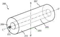
Fig. 2A shows the light emitting device 200, and in fig. 2B, 2C, 2D and 2E, a cross-sectional view of the light emitting device 200 along the line B-B' (fig. 2A) is shown. Referring to fig. 2A, 2B, 2C, 2D and 2E, the light emitting device 200 comprises a cylindrical vessel 203. The cylindrical vessel 203 is formed by a first cylindrical vessel 205 and a second cylindrical vessel 207 connected via a wall 209. The cylindrical vessel 203 is filled with a thermally conductive, optically transmissive fluid 211 in thermal contact with the inner surface 213 of the first cylindrical vessel 205 and the second cylindrical vessel 207. A plurality of LEDs 201 are positioned on an outer surface 215 of the first cylindrical vessel 205 and are thermally coupled to an inner surface 213 via a wall of the first cylindrical vessel 205. The LED201 is electrically connected to the electrical connector 221. During operation of the light emitting device 200, the LED201 is powered via the electrical connector 221 and generates light 217. Referring to fig. 2B, in a first embodiment of the light emitting device 200, the LED201 emits light 217 towards an outer surface area 215 of the first cylindrical vessel 205 where the LED is located. The light 217 passes through the fluid 211 and exits the light emitting device 200 via the second cylindrical vessel 207 as light 219 generated by the light emitting device 200. Referring to fig. 2C and 2D, in the second and third embodiments of the light emitting device 200, respectively, the LEDs 201 emit light 217 towards the outer surface area 215 of the first cylindrical vessel 205, the light 217 facing away from the outer surface 215 where the LEDs 201 are located. The light 217 passes through the first cylindrical vessel 205 and the fluid 211, and exits via the second cylindrical vessel 207The light emitting device 200 as light 219 generated by the light emitting device 200. Referring again to fig. 2A, 2B, 2C, 2D and 2E, heat generated locally by the LED201 is conducted via the first cylindrical vessel 205 to the fluid 211. The fluid 211 will transfer the heat further to the second cylindrical vessel 207 and the wall 209 via conduction and via convection within the fluid 211. This convection or movement of the fluid 211 is caused by buoyancy forces in the fluid due to the temperature difference within the fluid 211 between the hotter spot in the fluid 211 near the LEDs 201 and the cooler spot in the fluid 211 near the second cylindrical vessel 207 and the wall 209. Finally, the second cylindrical vessel 207 and the wall 209 transfer the heat further to the surroundings of the light emitting device 200. The heat conducting fluid 211 in this way serves to spread the heat generated by the LEDs 201 over a larger area formed by the second cylindrical vessel 207 and the wall 209. Because the fluid 211 is also light transmissive, the light 217 generated by the LED201 may be transmitted to the second cylindrical vessel 207 via the fluid 211 and out of the light emitting device 200 as light 219. The LEDs 201 are not in direct contact with the fluid 211, which makes the light emitting device 200 less complex (since otherwise special measures have to be taken to prevent short circuits). The distance d between the first cylindrical vessel 205 and the second cylindrical vessel 2071Is 3 mm. In some alternative embodiments, a distance d of 2, 4, 5, 6, 7, 8, 9 or 10mm may be selected1. The LEDs 201 are arranged in a linear array. The distance d between two adjacent LEDs 201 in the array2(not shown in fig. 2A-2E) is 10 mm. In some alternative embodiments, a distance d of 5, 6, 7, 8, 9, 11, 12, 13, 14 or 15mm may be selected2. In another alternative embodiment, the LED201 comprises a plurality of linear arrays of LEDs. The distance d between two adjacent LEDs 201 in an array2(not shown in fig. 2A-2E) the same, however in some alternative embodiments, different distances between two adjacent LEDs 201 may be applied.
Referring to fig. 2B, 2C, 2D and 2E, the heat generated by the LED201 is transferred to the liquid 211 via the first cylindrical vessel 205, so the temperature of the liquid 211 near the inner surface 213 of the first cylindrical vessel 205 increases at these locations. Due to the buoyancy, the locally heated liquid 211 starts to move. Finally, this produces, without using mechanical actuation, a total circulation of the liquid 211 inside the cylindrical vessel 203, as indicated with the arrow 223 (so-called thermosiphon effect). Because the LED201 is not positioned inside the cylindrical vessel 203, the movement of the liquid 211 is not impeded by the LED 201. The heated liquid 211 is in contact with the wall of the second cylindrical vessel 207, where heat is transferred via the wall of the second cylindrical vessel 207 to the surroundings of the light emitting device 200. Due to this thermo siphon effect, the heat removal to the surroundings of the light emitting device 200 is further improved.
Referring to fig. 2B, 2C and 2E, the light emitting device 200 comprises an array of LEDs 201 positioned parallel to the longitudinal axis C-C' of the first cylindrical vessel 205. Referring to fig. 2D, the light emitting device comprises three arrays of LEDs 201 positioned parallel to the longitudinal axis C-C' of the first cylindrical vessel. The three LED arrays are positioned in an asymmetric orientation along a radius of the first tubular vessel 205 (i.e., in this embodiment, a distance d along the radius3And d4Less than distance d5). This asymmetric orientation will further enhance the buoyancy in the liquid 211, thus improving the heat transfer to the surroundings of the light emitting device 200.
Fig. 3A shows a light emitting device 300, fig. 3B shows a cross-sectional view of the light emitting device 300 along the line D-D '(fig. 3A), and fig. 3C shows a cross-sectional view of an alternative embodiment of the light emitting device 300 along the line E-E' (fig. 3A). Referring to fig. 3A and 3B, the light emitting device 300 includes a spherical vessel 303. The spherical vessel 303 is formed by a first spherical vessel 305 and a second spherical vessel 307 connected via a wall 309. The spherical vessel 303 is filled with a thermally conductive, optically transmissive fluid 311 in thermal contact with the inner surface 313 of the first spherical vessel 305 and the second spherical vessel 307. A plurality of LEDs 301 are positioned on an outer surface 315 of the first spherical vessel 305 and are thermally coupled to an inner surface 313 via a wall of the first spherical vessel 305. The LED301 is electrically connected to an electrical connector 321. During operation of the light emitting device 300, the LED301 is powered via the electrical connector 321 and generates light 317. Downstream of the LED301, the light 317 passes through the first spherical vessel 305, the fluid 311, and exits the light emitting device 300 via the second spherical vessel 307 as light 31 generated by the light emitting device 3009. Heat generated locally by the LED301 is conducted via the first spherical vessel 305 to the fluid 311. The fluid 311 will transfer the heat further to the second spherical vessel 307 and the wall 309 via conduction and via convection within the fluid 311. The convection is caused by buoyancy forces resulting from the temperature difference within the fluid 311 between the hotter point in the fluid 311 near the LEDs 301 and the cooler point in the fluid 311 near the second spherical vessel 307 and the wall 309. Finally, the second spherical vessel 307 and the wall 309 transfer the heat further to the surroundings of the light emitting device 300. The heat conducting fluid 311 serves in this way to spread the heat generated by the LEDs 301 over a larger area formed by the second spherical vessel 307 and the wall 309. Because the fluid 311 is also light transmissive, the light 317 generated by the LED301 may be transmitted to the second spherical vessel 307 via the fluid 311 and out of the light emitting device 300 as light 319. The LED301 is not in direct contact with the fluid 311, which makes the light emitting device 300 less complex (since otherwise special measures have to be taken to prevent short circuits and/or degradation of the materials used in the LED 301). Distance d between first spherical vessel 305 and second spherical vessel 3071Is 3 mm. In some alternative embodiments, a distance d of 2, 4, 5, 6, 7, 8, 9 or 10mm may be selected1. The LEDs 301 are arranged in a matrix at various positions along different radii of the first spherical vessel 305. Distance d between two adjacent LEDs 3012Is 10 mm. In some alternative embodiments, a distance d of 5, 6, 7, 8, 9, 11, 12, 13, 14 or 15mm may be selected2. Distance d between two adjacent LEDs 3012The same, however, in some alternative embodiments, varying distances between two adjacent LEDs 301 may be applied. In some alternative embodiments, the LEDs 301 may be arranged in alternative patterns.
Referring to fig. 3C, in an alternative embodiment of the light emitting device 300, the LEDs 301 are positioned along a portion of the radius of the spherical vessel 303. The LEDs are asymmetrically oriented (i.e., in this embodiment, the distance d along the radius6、d7And d8Less than distance d9) To be positioned. Distance d6、d7And d8May be substantially the same or may differ in some alternative embodiments. The non-pairThe symmetric orientation will further enhance the buoyancy in the liquid 311 and thus improve the heat transfer to the surroundings of the light emitting device 300. The heat generated by the LED301 is transferred to the liquid 311 via the first cylindrical vessel 205, so the temperature of the liquid 311 near the inner surface 313 of the first spherical vessel 305 increases at these locations. In particular in case the light emitting device 300 is positioned horizontally along the axis D-D' (fig. 3A), the locally heated liquid 311 starts to move due to buoyancy. Finally, this produces, without using mechanical actuation, a total circulation of the liquid 311 inside the spherical vessel 303 as indicated with the arrow 323 (so-called thermosiphon effect). The heated liquid 311 comes into contact with the wall of the second cylindrical vessel 307, where the heat is transferred via the wall of the second cylindrical vessel 307 to the surroundings of the light emitting device 300. Due to this thermo siphon effect, the heat extraction to the surroundings of the light emitting device 300 is further improved. Because the LED301 is not positioned inside the spherical vessel 303, the movement of the liquid 311 is not impeded by the LED 301.
Fig. 4A shows a light emitting device 400A, and fig. 4B shows a light emitting device 400B. Fig. 4C and 4D show cross-sectional views of the light emitting device 400A, 400B along the line F-F'. Referring to fig. 4A, 4C and 4D, the light emitting apparatus 400A includes a semi-cylindrical vessel 403A. Referring to fig. 4B, 4C and 4D, the light emitting device 400B includes a hemispherical vessel 403B. Referring to fig. 4C, vessels 403A and 403B are formed from a first vessel 405 and a second vessel 407 connected via a wall 409. The vessels 403A, 403B are filled with a thermally conductive fluid 411 in thermal contact with the inner surface 413 of the first vessel 405 and the second vessel 407. A plurality of LEDs 401 are positioned on an outer surface 415 of the first vessel 405 and are thermally coupled to an inner surface 413 via a wall of the first vessel 405. The LED401 is electrically connected to an electrical connector 421 (fig. 4A and 4B). On the outer surface 415 of the first vessel 405, a reflective coating 423 is present. The reflective coating 423 is a specular reflective coating. Alternatively, the reflective coating 423 may be diffusely reflective. During operation of the light emitting device 400A, 400B, the LED401 is powered via the electrical connector 421 and generates light 417. The light 417 may exit the light emitting device 400A, 400B directly, or it may be reflected by the reflective coating 423, generating a light beam 419. The heat locally generated by the LEDs 401 is via the wall of the first vessel 405To fluid 411. The fluid 411 will transfer the heat further to the second vessel 407 and the wall 409 via conduction and via convection within the fluid 411. The convection is caused by buoyancy forces resulting from the temperature difference within the fluid 411 between the hotter spot in the fluid 411 near the LEDs 401 and the cooler spot in the fluid 411 near the second vessel 407 and the wall 409. Finally, the second vessel 407 and the wall 409 transfer the heat further to the surroundings of the light emitting device 400A, 400B. The heat conducting fluid 411 in this way serves to spread the heat generated by the LEDs 401 over a larger area formed by the second vessel 407 and the wall 409. The LED401 is not in direct contact with the fluid 411, which makes the light emitting device 400A, 400B less complex (since otherwise special measures have to be taken to prevent short circuits and/or degradation of the materials used in the LED 401). Distance d between the first vessel 405 and the second vessel 4071Is 3 mm. In some alternative embodiments, a distance d of 2, 4, 5, 6, 7, 8, 9 or 10mm may be selected1. The LEDs 401 are arranged in a matrix at various positions along different radii of the first vessel 405. Distance d between two adjacent LEDs 4012Is 10 mm. In some alternative embodiments, a distance d of 5, 6, 7, 8, 9, 11, 12, 13, 14 or 15mm may be selected2. Distance d between two adjacent LEDs 4012The same, however, in some alternative embodiments, varying distances between two adjacent LEDs 401 may be applied. In some alternative embodiments, the LEDs 401 may be arranged in an alternative pattern.
Referring to fig. 4D, some alternative embodiments of the light emitting apparatus 400A, 400B are the same as the embodiments shown in fig. 4A and 4C, and 4B and 4C, respectively, except that instead of the LEDs 401, there are so-called chip-on-board (COB) LED sources 425 as light sources. COB LED sources typically include multiple LED chips packaged together as one light source.
Referring to fig. 1A, 2A, 3A, 4A, and 4B, water is used as the heat transfer fluid. In some other embodiments, the fluid may include silicone oil, methanol, ethanol, acetone, water, fluorinated aliphatic organic compounds, aromatic organic compounds, and silicones, or mixtures thereof.
In some alternative embodiments, a halogen lamp or a high-intensity discharge lamp is used as the light source 101, 201, 301, or 401.
In an alternative embodiment, the thermally conductive, optically transmissive fluid comprises particles. The particles are selected from the group comprising scattering particles and inorganic luminescent particles or a combination thereof. Referring to fig. 1B, 2C, 2D, 3B and 3C, the light 117, 217 and 317 generated by the LEDs 101, 201 and 301 passes through the fluids 111, 211 and 311, respectively, and will be scattered by scattering particles (not shown in these figures) present in the fluids. Thus, the scattered light 119, 219, and 319 leaves the light emitting devices 100, 200, and 300. In an alternative embodiment, the light 117, 217 and 317 will be at least partially converted by the inorganic luminescent particles into light of another color. In another alternative embodiment, the walls of the first circular plate 105 and/or the second circular plate 107 (see fig. 1B), the walls of the first cylindrical vessel 205 and/or the second cylindrical vessel 207 (see fig. 2B, 2C and 2D) and the walls of the first spherical vessel 305 and/or the second spherical vessel 307 (see fig. 3B and 3C) comprise particles (not shown in these figures) selected from the group comprising scattering particles and inorganic luminescent particles or a combination thereof. The light 117, 217 and 317 generated by the LEDs 101, 201 and 301 passes through these walls and will be scattered by scattering particles present in the walls. Thus, the scattered light 119, 219, and 319 leaves the light emitting devices 100, 200, and 300. In an alternative embodiment, the light 117, 217 and 317 will be at least partially converted by the inorganic luminescent particles into light of another color. The scattering particles have a particle size in the range of 1-100 μm, preferably in the range of 1-10 μm. The scattering particles comprise one or more materials selected from the group of materials comprising polymeric materials (e.g., polytetrafluoroethylene or PMMA) and hollow spherical particles of ceramic materials (e.g., silica or alumina). In one embodiment, LEDs 101, 201, and 301 comprise blue emitting LEDs, and the phosphor particles comprise Al3A5O12:Ce3+Material and optionally additional CaAlN3:Eu2+A material. A part of the blue light is converted into yellow or green or yellow/green light which is mixed with unconverted blue light into white light. Optionally, red light is added by another luminescent material to generate warm white light.
In another alternative embodiment, the optical refractive index of the thermally conductive and light transmissive fluid 111, 211, 311 and the optical refractive index of at least a portion of the container 103, 203, 303 are tuned to each other. Refractive index (n) of heat transfer fluidfluid) In the range of 1-5. The refractive index (n) of the wall of the first circular plate 105 and/or the second circular plate 107 (see fig. 1B), the wall of the first cylindrical vessel 205 and/or the second cylindrical vessel 207 (see fig. 2B, 2C, and 2D), and the wall of the first spherical vessel 305 and/or the second spherical vessel 307 (see fig. 3B and 3C)container) Respectively in the range of 1-5. By making nfluidAnd ncontainerAre tuned to each other, a desired optical effect can be achieved. Optical refractive index (n) of the fluid 111, 211, 311fluid) With the optical refractive index (n) of the material of at least a part of the container 103, 203, 303container) Comparison (n)fluid≈ncontainer). In case the light 117, 217, 317 propagates through the fluid 111, 211, 311, subsequently through the second region 107, 207, 307 of the container 103, 203, 303 and then exits the light emitting device 100, 200, 300, the light 117, 217, 317 will not be substantially refracted by the material of the second region 107, 207, 307 of the container 103, 203, 303 and the light emitting device 100, 200, 300 may generate diffuse light. In an alternative embodiment, the optical refractive index of the fluid is greater than the optical refractive index of at least a portion of the container (n)fluid>ncontainer). In case the light propagates through the fluid 111, 211, 311, subsequently through the second region of the container 103, 203, 303 and then exits the light emitting device 100, 200, 300, the light 117, 217, 317 will be substantially refracted by the material of the second region 107, 207, 307 of the container 103, 203, 303 and the light emitting device 100, 200, 300 may generate beam shaped light. The amount of beam shaping is nfluidAnd ncontainerIs determined by the ratio of (a); as the ratio increases, for nfluid>ncontainerThe amount of beam shaping increases. In another alternative embodiment, the optical refractive index of the fluid is less than the optical refractive index of at least a portion of the container (n)fluid<ncontainer). After the light propagates through the fluid 111, 211, 311 and subsequently through the container 103,203. 303 and then leave the light emitting device 100, 200, 300, most of the light 117, 217, 317 will be reflected back by the second area 107, 207, 307 of the container 103, 203, 303 and may leave the light emitting device 100, 200, 300 via the first area 105, 205, 305 of the container 103, 203, 303. The quantity of light reflected is nfluidAnd ncontainerIs determined by the ratio of (a); as the ratio decreases, for nfluid<ncontainerThe amount of reflected light increases.
In another alternative embodiment, the walls of the first circular plate 105 and/or the second circular plate 107 (see fig. 1B), the walls of the first cylindrical vessel 205 and/or the second cylindrical vessel 207 (see fig. 2B, 2C, and 2D), and the walls of the first spherical vessel 305 and/or the second spherical vessel 307 (see fig. 3B and 3C) comprise one or more optical elements. Referring to fig. 2E, an optical element 225 is fabricated on the outer surface region 215 of the first cylindrical vessel 205. The optical element is a microlens for light collimation. The LED201 emits light 217 towards an outer surface area 215 of the first cylindrical vessel 205. Subsequently, the light is collimated by the micro-lens 225, and the collimated light 227 exits the light emitting device 200 via the second cylindrical vessel 207. Alternatively, the optical element 225 may comprise one or more elements comprising a material having a refractive index different from the refractive index of the material of the first cylindrical vessel 205 and/or the fluid 211.
In another alternative embodiment, the walls of the first circular plate 105 and/or the second circular plate 107 (see fig. 1B), the walls of the first cylindrical vessel 205 and/or the second cylindrical vessel 207 (see fig. 2B, 2C and 2D) and the walls of the first spherical vessel 305 and/or the second spherical vessel 307 (see fig. 3B and 3C) comprise one or more elements for improving the mechanical strength of the walls. In case the light emitting device has a higher output power (e.g. in the range of 150-600W), the cooling area (e.g. the area of the inner surface 113 with reference to FIG. 1B) has to be larger, e.g. in the range of 0.5-1m2Within the range of (1). Thus, a greater hydrostatic pressure is generated on the first circular plate 105 and/or the second circular plate 107 (see fig. 1B) and thus also on the cylindrical vessel 103. Reference toIn fig. 1D, the first circular plate 105 and the second circular plate 107 comprise elements 125 attached to both the first circular plate 105 and the second circular plate 107. The element 125 has a diameter d11A cylindrical shape in the range of 2mm-30 mm. Alternatively, the elements may have different shapes, such as triangular or square. The elements 125 may comprise a light transmissive material, or alternatively they may comprise an optically reflective coating (such as TiO) coated2) The metal of (1). The elements 125 improve the mechanical strength of the light emitting device 100 and by keeping the dimensions (e.g. diameter in case of cylindrically shaped elements 125) small, the convection of the fluid 111 during operation of the light emitting device 100 will be disturbed only to a small extent. Referring to fig. 1E, in an alternative embodiment, the first circular plate 105 and the second circular plate 107 comprise elongated elements 127 for improving the mechanical strength of the light emitting device 100. The elongated element 127 is positioned at (i) the inner surface 113 of the first circular plate 105, (ii) the inner surface 113 of the second circular plate 107, (iii) the outer surface 115 of the first circular plate 105, and (iv) the outer surface 121 of the second circular plate 107. Alternatively, the elongated element 127 is positioned according to one, two or three selections from the group of (i) - (iv) as indicated in the previous sentence. The elongated element 127 may extend along the surfaces 113, 115 and 121 or only a portion thereof. The elongated element is preferably made of a light-transmissive material, such as for example polycarbonate or another polymer material.
Fig. 5 shows a lamp 500 comprising one or more light emitting devices according to fig. 1A-1C, 2A-2D, 3A-3C or 4A-4D. The lamp 500 may be used for different applications, such as indoor lighting, outdoor lighting, disinfection purposes, among others.
Fig. 6 shows a luminaire 600, the luminaire 600 comprising one or more light emitting devices according to fig. 1A-1C, 2A-2D, 3A-3C or 4A-4D or one or more lamps according to fig. 5. The luminaire 600 may be used for different applications, such as indoor lighting, outdoor lighting, disinfection purposes, among others.
Fig. 7 shows the results of thermal experiments performed for the light emitting device according to fig. 2A and 2C. In FIG. 7, the unit of pairs is Watt [ P ]]Shows the electric power in units of ℃ [ T ℃s]The temperature of the LED footprint. First cylinderThe length of the forming vessel 205 and the second cylindrical vessel 207, respectively, is 300 mm. One LED array 240mm long and comprising 24 LEDs is used. The diameter of the second cylindrical vessel 207 is 20 mm. The diameter variation of the first cylindrical vessel 205: 14mm (see B in FIG. 5, corresponding to a distance d of 3mm1) 16mm (see C in fig. 6, corresponding to a distance d of 2mm1) And 18mm (see D in FIG. 6, corresponding to a distance D of 1mm1). The liquid 211 is composed of water. The configuration in which a single cylindrical vessel is used with one LED array without using a container with cooling liquid is referred to as a in fig. 6. As can be seen from fig. 6, the lighting device according to the invention has a lower T at a comparable electrical power P compared to a lighting device without a container with a cooling liquidsThe value is, for example, about 50 ℃ to 70 ℃ at an electric power of 5W. Thus, the light emitting device according to the invention is directed to TsCan be driven with higher electrical power, e.g. for a T equal to 96 ℃sThe values are 13W to 7W.
Claims (14)
1. A light emitting device (300) comprising at least one light source (301) and a closed container (303) comprising a first spherical vessel (305) and a second spherical vessel (307), the second spherical vessel (307) being arranged opposite to the first spherical vessel (305), the at least one light source (301) being arranged on an outer surface (315) of the first spherical vessel (305) of the closed container (303) and being thermally coupled to an inner surface (313) of the first spherical vessel (305), characterized in that:
the second spherical vessel (307) is at a distance (d) greater than zero mm1) Surrounding the first spherical vessel (305) to form a space between the first spherical vessel (305) and the second spherical vessel (307), the space being filled with a heat conducting fluid (311), and wherein the at least one light source (301) is arranged asymmetrically along a radius of the first spherical vessel (305) such that the heat conducting fluid (311) is cyclically movable in the space.
2. The light emitting device according to claim 1, wherein the thermally conductive fluid (311) is light-transmissive, and wherein at least a portion of the first spherical vessel (305) and the second spherical vessel (307) is light-transmissive.
3. A light emitting device according to claim 1 or 2, wherein said distance (d)1) In the range of 1-10 mm.
4. A light emitting device according to claim 1 or 2, wherein said thermally conductive optically transparent fluid (311) has a refractive index between 5-108And 3.1010A Grashof number in the range between.
5. A light emitting device according to claim 1 or 2, wherein at least a part of the container (303) and/or the heat conducting fluid (311) comprises particles selected from the group comprising scattering particles and inorganic luminescent particles or a combination thereof.
6. A light emitting device according to claim 1 or 2, wherein at least a part of the container (303) is made of one or more materials selected from the group comprising light transmissive organic materials, glass materials, light transmissive ceramic materials and silicone materials.
7. A light emitting device according to claim 1 or 2, wherein the container (303) comprises one or more optical elements (225) for guiding light emitted during operation of the device in a predetermined direction.
8. A light emitting device according to claim 3, wherein said distance (d)1) In the range of 1-7 mm.
9. The light emitting device of claim 8, wherein the distance (d)1) In the range of 2-7 mm.
10. The light emitting device according to claim 9, wherein the distance (d)1) In the range between 2-4 mm.
11. A light emitting device according to claim 4, wherein said thermally conductive optically transparent fluid (311) has a refractive index between 6 and 109And 3.1010A Grashof number in the range between.
12. A light emitting device according to claim 11, wherein said thermally conductive optically transparent fluid (311) has a refractive index between 1-1010And 3.1010A Grashof number in the range between.
13. A lamp (500) comprising at least one light emitting device (300) according to any one of claims 1-12.
14. A luminaire (600) comprising at least one light emitting device (300) according to any one of claims 1-12, or comprising a lamp (500) according to claim 13.
Applications Claiming Priority (5)
| Application Number | Priority Date | Filing Date | Title |
|---|---|---|---|
| EP14181742 | 2014-08-21 | ||
| EP14181742.9 | 2014-08-21 | ||
| EP14199929 | 2014-12-23 | ||
| EP14199929.2 | 2014-12-23 | ||
| PCT/EP2015/068005 WO2016026695A1 (en) | 2014-08-21 | 2015-08-05 | Light emitting device |
Publications (2)
| Publication Number | Publication Date |
|---|---|
| CN106662294A CN106662294A (en) | 2017-05-10 |
| CN106662294B true CN106662294B (en) | 2020-09-11 |
Family
ID=53762198
Family Applications (1)
| Application Number | Title | Priority Date | Filing Date |
|---|---|---|---|
| CN201580044797.8A Active CN106662294B (en) | 2014-08-21 | 2015-08-05 | Light emitting device |
Country Status (5)
| Country | Link |
|---|---|
| US (1) | US10473316B2 (en) |
| EP (1) | EP3183492B1 (en) |
| JP (1) | JP6995619B2 (en) |
| CN (1) | CN106662294B (en) |
| WO (1) | WO2016026695A1 (en) |
Families Citing this family (3)
| Publication number | Priority date | Publication date | Assignee | Title |
|---|---|---|---|---|
| EP3551933B1 (en) * | 2016-12-09 | 2020-08-19 | Signify Holding B.V. | A lighting module and a luminaire comprising the lighting modulespe |
| JP7035499B2 (en) * | 2017-12-14 | 2022-03-15 | 豊田合成株式会社 | Ultraviolet light irradiation sterilizer |
| CN111963991B (en) * | 2020-09-05 | 2022-11-22 | 广东智飞达照明科技有限公司 | Solar LED street lamp with protection function |
Citations (4)
| Publication number | Priority date | Publication date | Assignee | Title |
|---|---|---|---|---|
| US5890794A (en) * | 1996-04-03 | 1999-04-06 | Abtahi; Homayoon | Lighting units |
| CN201652279U (en) * | 2010-05-06 | 2010-11-24 | 艾迪光电(杭州)有限公司 | Air-cooling and liquid-cooling combined radiating device |
| CN201892047U (en) * | 2010-07-08 | 2011-07-06 | 艾迪光电(杭州)有限公司 | Light emitting diode lamp |
| WO2013082803A1 (en) * | 2011-12-09 | 2013-06-13 | GE Lighting Solutions, LLC | Led lamp having magnetic thermal management |
Family Cites Families (41)
| Publication number | Priority date | Publication date | Assignee | Title |
|---|---|---|---|---|
| DE541952C (en) | 1932-01-16 | Emil Busch A G | Illuminated mirror designed as a cooling cell | |
| JPH03180295A (en) | 1989-12-07 | 1991-08-06 | Osaka Prefecture | Backing material for welding deformed steel bar made of sintered ceramics |
| JP3180295B2 (en) | 1991-10-28 | 2001-06-25 | 株式会社東京精密 | Dicing equipment |
| JP3535343B2 (en) * | 1997-05-16 | 2004-06-07 | 三菱電機株式会社 | Magnetic field application type single crystal manufacturing equipment |
| US20020131683A1 (en) * | 2001-03-15 | 2002-09-19 | Doerr Christopher Richard | Planar lightwave wavelength blocker devices using micromachines |
| DE102005013208A1 (en) | 2004-03-21 | 2005-10-27 | Späth, Christian, Dipl.-Designer | Lighting unit has light emitting diodes mounted in housing tube filled with a cooling liquid |
| US7086767B2 (en) * | 2004-05-12 | 2006-08-08 | Osram Sylvania Inc. | Thermally efficient LED bulb |
| JP2006108010A (en) | 2004-10-08 | 2006-04-20 | Ushio Inc | Heating unit |
| US7288798B2 (en) * | 2005-06-02 | 2007-10-30 | Lighthouse Technology Co., Ltd | Light module |
| US7916897B2 (en) * | 2006-08-11 | 2011-03-29 | Tessera Technologies Ireland Limited | Face tracking for controlling imaging parameters |
| WO2008133304A1 (en) | 2007-04-25 | 2008-11-06 | Gs Yuasa Corporation | Light source device |
| CN101463989B (en) | 2007-12-18 | 2011-07-06 | 富士迈半导体精密工业(上海)有限公司 | Underwater illumination device |
| JP4479805B2 (en) * | 2008-02-15 | 2010-06-09 | ソニー株式会社 | Lens, light source unit, backlight device, and display device |
| US8892407B2 (en) | 2008-10-01 | 2014-11-18 | Exxonmobil Upstream Research Company | Robust well trajectory planning |
| TW201019431A (en) | 2008-11-03 | 2010-05-16 | Wen-Qiang Zhou | Insulating and heat-dissipating structure of an electronic component |
| US8430531B2 (en) | 2009-01-08 | 2013-04-30 | Terralux, Inc. | Advanced cooling method and device for LED lighting |
| US20100187961A1 (en) | 2009-01-27 | 2010-07-29 | Keith Scott | Phosphor housing for light emitting diode lamp |
| IT1393248B1 (en) * | 2009-03-03 | 2012-04-12 | Ideal Standard Intl Bvba | BODY TREATMENT SYSTEM BY LIQUID VIBRATIONS |
| CN101655189A (en) * | 2009-07-16 | 2010-02-24 | 艾迪光电(杭州)有限公司 | Hollow liquid cooling LED bar-shaped lamp |
| US20120250333A1 (en) | 2009-10-26 | 2012-10-04 | Wen-Chiang Chou | Insulating and Dissipating Heat Structure of an Electronic Part |
| DE102010001007B4 (en) * | 2010-01-19 | 2013-01-03 | Osram Ag | Luminaire for illuminating a target area by means of backward reflection of light from a light-emitting diode module on a reflector |
| US8262249B2 (en) * | 2010-01-19 | 2012-09-11 | Lightel Technologies Inc. | Linear solid-state lighting with broad viewing angle |
| CN102157503A (en) * | 2010-02-12 | 2011-08-17 | 美昌(全球)股份有限公司 | Light-emitting diode structure capable of emitting light and enhancing heat radiation efficiency and LED (light-emitting diode) lamp |
| US8322947B2 (en) * | 2010-06-11 | 2012-12-04 | Neumann Duane A | Flexible skid steer attachment device |
| US8587185B2 (en) | 2010-12-08 | 2013-11-19 | Cree, Inc. | Linear LED lamp |
| CN202141017U (en) | 2011-06-27 | 2012-02-08 | 徐大鹏 | A semiconductor solid state lighting tube |
| CN202118634U (en) * | 2011-07-05 | 2012-01-18 | 汪绍芬 | Light-emitting diode (LED) module light source with low thermal resistance and high lighting effect |
| JP2013105711A (en) * | 2011-11-16 | 2013-05-30 | Toshiba Lighting & Technology Corp | Luminaire |
| US9482421B2 (en) * | 2011-12-30 | 2016-11-01 | Cree, Inc. | Lamp with LED array and thermal coupling medium |
| CN202691849U (en) * | 2012-07-13 | 2013-01-23 | 梁允生 | Novel headlamp with integrated light emitting diode |
| US10077722B2 (en) * | 2012-07-24 | 2018-09-18 | GM Global Technology Operations LLC | Control of engine EGR with backpressure control valve |
| JP6004837B2 (en) * | 2012-08-22 | 2016-10-12 | 三菱電機照明株式会社 | Lighting lamp |
| JP3180295U (en) * | 2012-09-28 | 2012-12-13 | グローバル・リンク株式会社 | Lighting device |
| CN103807726B (en) | 2012-11-02 | 2017-12-19 | 万德莱特有限公司 | Lighting apparatus |
| CN102943967B (en) | 2012-11-08 | 2014-08-27 | 浙江阳光照明电器集团股份有限公司 | LED (Light Emitting Diode) tubular lamp with liquid heat transfer effect |
| JP2014102995A (en) | 2012-11-20 | 2014-06-05 | Toshiba Corp | Lighting device |
| CN203068250U (en) | 2013-02-28 | 2013-07-17 | 北京艾久瓦光电科技有限公司 | Liquid-cooled LED lamp |
| US8899794B2 (en) * | 2013-03-15 | 2014-12-02 | Bby Solutions, Inc. | LED bulb optical system with uniform light distribution |
| CN103234131B (en) * | 2013-05-09 | 2016-04-06 | 杭州电子科技大学 | The optocoupler mixture supplement heat rejecter LED lamp device of high light-emitting efficiency |
| JP6235283B2 (en) * | 2013-09-24 | 2017-11-22 | 株式会社東芝 | Lighting device |
| CN203757418U (en) * | 2014-01-17 | 2014-08-06 | 四川新力光源股份有限公司 | LED illuminating lamp |
-
2015
- 2015-08-05 JP JP2017509689A patent/JP6995619B2/en active Active
- 2015-08-05 US US15/505,289 patent/US10473316B2/en active Active
- 2015-08-05 WO PCT/EP2015/068005 patent/WO2016026695A1/en active Application Filing
- 2015-08-05 EP EP15744607.1A patent/EP3183492B1/en active Active
- 2015-08-05 CN CN201580044797.8A patent/CN106662294B/en active Active
Patent Citations (4)
| Publication number | Priority date | Publication date | Assignee | Title |
|---|---|---|---|---|
| US5890794A (en) * | 1996-04-03 | 1999-04-06 | Abtahi; Homayoon | Lighting units |
| CN201652279U (en) * | 2010-05-06 | 2010-11-24 | 艾迪光电(杭州)有限公司 | Air-cooling and liquid-cooling combined radiating device |
| CN201892047U (en) * | 2010-07-08 | 2011-07-06 | 艾迪光电(杭州)有限公司 | Light emitting diode lamp |
| WO2013082803A1 (en) * | 2011-12-09 | 2013-06-13 | GE Lighting Solutions, LLC | Led lamp having magnetic thermal management |
Also Published As
| Publication number | Publication date |
|---|---|
| JP6995619B2 (en) | 2022-01-14 |
| JP2017524238A (en) | 2017-08-24 |
| EP3183492B1 (en) | 2021-06-30 |
| US20170261194A1 (en) | 2017-09-14 |
| CN106662294A (en) | 2017-05-10 |
| WO2016026695A1 (en) | 2016-02-25 |
| EP3183492A1 (en) | 2017-06-28 |
| US10473316B2 (en) | 2019-11-12 |
Similar Documents
| Publication | Publication Date | Title |
|---|---|---|
| JP5654447B2 (en) | An illumination device comprising an LED and a transmissive support having a luminescent material. | |
| JP6058545B2 (en) | Illumination device having a light guide plate | |
| JP6165155B2 (en) | Illumination unit including a waveguide | |
| RU2673878C2 (en) | Lighting device with optical element having fluid passage | |
| JP2011520281A (en) | Illumination device comprising an LED having a self-supporting grid comprising a luminescent material and a method of making a self-supporting grid | |
| KR20120055581A (en) | Solid state light with optical guide and integrated thermal guide | |
| US8672497B2 (en) | Phosphor plate and lighting device | |
| CN110637247B (en) | Lighting device and lighting system | |
| CN106662294B (en) | Light emitting device | |
| CN106233067A (en) | Comprise the linear lighting arrangements of solid-state of light emitting phosphor | |
| JP6133306B2 (en) | Illumination unit with lamp shade | |
| EP2959218B1 (en) | Lighting device | |
| KR101772623B1 (en) | Phosphor coating matrix and lighting device | |
| US20140265811A1 (en) | Led light bulb with a phosphor structure in an index-matched liquid | |
| KR101780408B1 (en) | Phosphor coating matrix and lighting device | |
| KR20120057261A (en) | Phosphor coating matrix and lighting device | |
| KR101821811B1 (en) | Phosphor coating matrix and lighting device |
Legal Events
| Date | Code | Title | Description |
|---|---|---|---|
| PB01 | Publication | ||
| PB01 | Publication | ||
| SE01 | Entry into force of request for substantive examination | ||
| SE01 | Entry into force of request for substantive examination | ||
| CB02 | Change of applicant information |
Address after: The city of Eindhoven in Holland Applicant after: PHILIPS LIGHTING HOLDING B.V. Address before: The city of Eindhoven in Holland Applicant before: PHILIPS LIGHTING HOLDING B.V. |
|
| CB02 | Change of applicant information | ||
| GR01 | Patent grant | ||
| GR01 | Patent grant |