CN1066103C - Ink jet recording apparatus and method for recovering an ink jet recording head used for such apparatus - Google Patents
Ink jet recording apparatus and method for recovering an ink jet recording head used for such apparatus Download PDFInfo
- Publication number
- CN1066103C CN1066103C CN95101472A CN95101472A CN1066103C CN 1066103 C CN1066103 C CN 1066103C CN 95101472 A CN95101472 A CN 95101472A CN 95101472 A CN95101472 A CN 95101472A CN 1066103 C CN1066103 C CN 1066103C
- Authority
- CN
- China
- Prior art keywords
- ink
- printing ink
- jet print
- print head
- ink jet
- Prior art date
- Legal status (The legal status is an assumption and is not a legal conclusion. Google has not performed a legal analysis and makes no representation as to the accuracy of the status listed.)
- Expired - Fee Related
Links
- 238000000034 method Methods 0.000 title claims description 25
- 230000007246 mechanism Effects 0.000 claims abstract description 31
- 238000007639 printing Methods 0.000 claims description 119
- PLXMOAALOJOTIY-FPTXNFDTSA-N Aesculin Natural products OC[C@@H]1[C@@H](O)[C@H](O)[C@@H](O)[C@H](O)[C@H]1Oc2cc3C=CC(=O)Oc3cc2O PLXMOAALOJOTIY-FPTXNFDTSA-N 0.000 claims description 18
- 238000007641 inkjet printing Methods 0.000 claims description 8
- 238000001556 precipitation Methods 0.000 claims description 8
- 238000011084 recovery Methods 0.000 abstract description 12
- 239000000203 mixture Substances 0.000 abstract description 8
- 230000000717 retained effect Effects 0.000 abstract 1
- 239000000976 ink Substances 0.000 description 262
- 238000003860 storage Methods 0.000 description 10
- 239000007788 liquid Substances 0.000 description 9
- 239000012530 fluid Substances 0.000 description 8
- 239000003086 colorant Substances 0.000 description 7
- 229920001971 elastomer Polymers 0.000 description 5
- 239000005060 rubber Substances 0.000 description 5
- 238000005516 engineering process Methods 0.000 description 4
- 230000000694 effects Effects 0.000 description 3
- 238000010438 heat treatment Methods 0.000 description 3
- 238000002156 mixing Methods 0.000 description 3
- 239000007921 spray Substances 0.000 description 3
- 238000009835 boiling Methods 0.000 description 2
- 238000004040 coloring Methods 0.000 description 2
- 230000008602 contraction Effects 0.000 description 2
- 230000008878 coupling Effects 0.000 description 2
- 238000010168 coupling process Methods 0.000 description 2
- 238000005859 coupling reaction Methods 0.000 description 2
- 238000009792 diffusion process Methods 0.000 description 2
- 230000037361 pathway Effects 0.000 description 2
- 230000008569 process Effects 0.000 description 2
- 239000000700 radioactive tracer Substances 0.000 description 2
- 239000007787 solid Substances 0.000 description 2
- 230000003321 amplification Effects 0.000 description 1
- 230000005540 biological transmission Effects 0.000 description 1
- 230000015572 biosynthetic process Effects 0.000 description 1
- 238000006243 chemical reaction Methods 0.000 description 1
- 239000002131 composite material Substances 0.000 description 1
- 238000010276 construction Methods 0.000 description 1
- 230000002950 deficient Effects 0.000 description 1
- 238000007599 discharging Methods 0.000 description 1
- 238000009826 distribution Methods 0.000 description 1
- 238000003384 imaging method Methods 0.000 description 1
- 239000004615 ingredient Substances 0.000 description 1
- 230000014759 maintenance of location Effects 0.000 description 1
- 239000000463 material Substances 0.000 description 1
- 230000006911 nucleation Effects 0.000 description 1
- 238000010899 nucleation Methods 0.000 description 1
- 238000003199 nucleic acid amplification method Methods 0.000 description 1
- 238000012856 packing Methods 0.000 description 1
- 238000003825 pressing Methods 0.000 description 1
- 238000005086 pumping Methods 0.000 description 1
- 230000004044 response Effects 0.000 description 1
- 239000004094 surface-active agent Substances 0.000 description 1
- 239000000725 suspension Substances 0.000 description 1
- 210000005239 tubule Anatomy 0.000 description 1
Images


Classifications
-
- B—PERFORMING OPERATIONS; TRANSPORTING
- B41—PRINTING; LINING MACHINES; TYPEWRITERS; STAMPS
- B41J—TYPEWRITERS; SELECTIVE PRINTING MECHANISMS, i.e. MECHANISMS PRINTING OTHERWISE THAN FROM A FORME; CORRECTION OF TYPOGRAPHICAL ERRORS
- B41J2/00—Typewriters or selective printing mechanisms characterised by the printing or marking process for which they are designed
- B41J2/005—Typewriters or selective printing mechanisms characterised by the printing or marking process for which they are designed characterised by bringing liquid or particles selectively into contact with a printing material
- B41J2/01—Ink jet
- B41J2/135—Nozzles
- B41J2/165—Prevention or detection of nozzle clogging, e.g. cleaning, capping or moistening for nozzles
- B41J2/16517—Cleaning of print head nozzles
- B41J2/1652—Cleaning of print head nozzles by driving a fluid through the nozzles to the outside thereof, e.g. by applying pressure to the inside or vacuum at the outside of the print head
- B41J2/16523—Waste ink transport from caps or spittoons, e.g. by suction
Landscapes
- Engineering & Computer Science (AREA)
- Environmental & Geological Engineering (AREA)
- Ink Jet (AREA)
Abstract
A suction recovery mechanism for an ink jet recording apparatus for recording by selectively supporting a different ink jet recording head on a carriage includes a single cap member capable of covering the entire ink discharge port area of each of the different ink jet recording heads selectively supported on the carriage, and a suction mechanism communicating section provided for the cap member in order to perform suction recoveries of each of the ink jet recording heads selectively supported on the carriage. This suction mechanism communicating section is conductively connected with a suction mechanism for sucking ink retained in the cap member. With this arrangement, it becomes possible to widen the range of kinds of images which can be recorded by the apparatus. Also, with the provision of an additional structure to arrange a suction port within a black ink discharge area in the cap member which is conductively connected to a suction pump, it is possible to perform suction recoveries for a color recording head while suppressing color mixture at the time of recoveries.
Description
The present invention relates to a kind of ink-jet recording apparatus and recover the ink jet recording head used method of this kind device.More particularly, the present invention relates to a kind of such ink-jet recording apparatus of ink jet print head that a cap cover part is housed with the usefulness that covers output different densities (concentration) printing ink, and with a kind of method of recovering used each ink jet print head of this kind device.
Routinely, existing a kind of technology that makes the image forming that is recorded.This technology has been used an ink gun that has spout with the output ink droplet, the jet pipe that links to each other with spout, the energy generating device that some are equipped for nozzle assembly output ink droplet, the shared fluid storage compartment in order to establish to many nozzles supply printing ink, storage China ink case that has a certain amount of printing ink, one and miscellaneous part drive the electronic signal terminal of energy generating device jointly.This ink jet head cartridge makes it link to each other with apparatus main body thereby fix ink gun on a skeleton on this apparatus main body (printing machine), so that can be the output of record ink droplet according to pictorial information.
Yet according to above-mentioned routine techniques, what adorned on the apparatus main body is the ink gun of a same kind, and the result is restricted this problem with regard to having produced the image kind that can write down.
In addition, the problem that is run in multiple ink gun is installed in conventional ink-jet recording apparatus on the same apparatus main body replaceablely is, because have the multiple ink gun of multiple delivery outlet surface structure to need the cap of multiple structure, this device size is generally speaking just bigger.
Also have, from different viewpoints, at least one is installed on the balladeur train in several shower nozzles if can select, formation can be exported the structure of multiple inks, so, generally speaking, can not realize that but stable suction recovers, reason is can produce different fluid resistances in every printing ink output channel, or because of due to every kind of ink performance difference.Therefore, offset this contradiction, common way is to assemble cap one by one respectively for each printing ink delivery outlet zone to recover to realize suction.Yet, in the case, use this single cap can not realize that not only any suction recovers, and, in some cases,, also may this cap of logotype cover delivery outlet and all be unable to handle if comprise in the different ink jet print heads that is only used a monochromatic shower nozzle.So, when different ink jet print heads is equipped with the different distributions situation of delivery outlet, quite effectively aspirate recovery and be equipped with a plurality of different caps and suction pump with regard to being required to be realization, or need under the situation that only should be used for a suction pump a plurality of caps, to be equipped with the facility of conversion suction channel.Obviously, such configuration generally speaking can make this device become big, and makes its structure complicated more.
In addition, when technology all was equipped with cap for each printing ink delivery outlet zone routinely, it is less relatively that the quantity of ink that is sucked often becomes.This comes, and in the time of will filling every minor diameter pipe or tubule path in order to use required restore funcitons, such a little bit printing ink is just not much of that, thereby in some cases, printing ink is sticked together, and recovers to produce in the path printing ink deposited phenomenon in suction.This is a problem that remains to be added again solution.
The present invention is after having put above-mentioned technology opinion in order, having changed technical thought designs, its purpose is actively to use in aspirating the recovery operation process ink mixture to contain the printing ink precipitation and adhere to suction recovery path, thereby a kind of method that makes the stable recovery of ink gun is provided.
Another object of the present invention provides a kind of ink-jet recording apparatus, it comprises a common carriage, be used to support with the multiple ink gun of the multiple ink gun that fixedly has different number nozzles, ink gun or output monochrome ink or polychrome printing ink with different spray nozzles spacing be equipped with of being connected the electronic signal terminal end surface for each ink gun and be electrically connected assembly; It also comprises the cap on the record ink droplet delivery outlet surface of only shared each ink gun of covering, thereby can select recordable image type on a large scale by the mode of hyperphoric above-mentioned a plurality of ink guns.In addition, the present invention also provides a kind of method of recovering the used ink jet print head of each this kind device.
A further object of the invention is, a kind of ink-jet recording apparatus is provided, and its size generally speaking ink-jet recording apparatus than routine is little, and some caps that conventional equipment is equipped with multiple structure are used for the multiple ink gun that not isostructure delivery outlet surface is arranged accordingly.This purpose is that the single shared cap by the assembling according to the present invention covers in many ink guns the delivery outlet surface of each and realizes; In addition, also provide a kind of method of recovering each used ink jet print head of this device.
A further object of the invention is, a kind of ink-jet recording apparatus is provided, it has the recovery mechanism that realizes aspirating recovery by single cap cover part, and this cap can cover each assembly in the selected delivery outlet assembly that is contained in ink jet print heads different on the ink-jet recording apparatus, in the different ink jet print heads of selecting for record each all be contained in can a balladeur train with electronic mode and the mechanical system supporting ink gun of being adorned on; And, a kind of method of recovering the used some ink jet print heads of this device also is provided.
A further object of the invention is, a kind of ink-jet recording apparatus is provided, wherein as the suction pump coupling assembling and the pump orifice of the cap cover part of usefulness, central area facing to black ink record ink gun delivery outlet zone, simultaneously, in the scope corresponding with the black ink output oral region of polychrome ink jet print head, polychrome printing ink is partial to but not delivery outlet zone one side of black ink in the position of facing; And, a kind of method of recovering used each ink jet print head of this device also is provided.
A further object of the invention is, a kind of each method that is restored that enables to select the variety classes ink jet print head that assembles is provided, these ink jet print heads are pressed the output yellow by the ink jet print head of an output black printing ink and by the delivery outlet zone, pinkish red, dark blue, the tactic polychromatic ink gun of black ink is formed, and assemble to such an extent that can make yellow, pinkish red, dark blue, the precipitation density of black ink satisfies different relations, thereby realizes that by the single cap cover part that can cover each these different ink jet print head delivery outlet unit fully suction recovers; In addition, the above-mentioned pump orifice that is used as the cap cover part of suction pump coupling assembling, adorned in the face of the central area in black ink-jet record head delivery outlet zone, simultaneously, in the such scope in black ink delivery outlet zone, in the face of being partial to above-mentioned navy blue printing ink delivery outlet zone one side in the position in the face of above-mentioned polychrome ink jet print head.
A further object of the invention is, for selectively a different ink jet print head being bearing in the ink-jet recording apparatus of an enterprising line item of balladeur train, provides a cover suction to recover mechanism, and it comprises:
Can cover the single cap cover part of selecting to be bearing in the whole printing ink delivery outlet of each the different ink jet print head zone on the balladeur train;
Recover and is the aspirating mechanism connected component of cap cover part assembling for each selected ink jet print head that is bearing on the balladeur train is aspirated, the aspirating mechanism that retains printing ink in this aspirating mechanism connected component conductibility ground and the suction cap cover part links to each other.
A further object of the invention is, provides a kind of ink-jet recording apparatus for selecting each different ink gun to be bearing in the enterprising line item of balladeur train, and it comprises:
Can cover the single cap cover part of selecting to be bearing in the whole printing ink delivery outlet of each the different ink jet print head zone on the balladeur train;
Retain the aspirating mechanism of printing ink in the one cover suction cap cover part;
For each selected ink jet print head that is bearing on the balladeur train being aspirated recovery is the aspirating mechanism connected component of cap cover part assembling, and this aspirating mechanism is communicated with partly and links to each other with aspirating mechanism.
A further object of the invention is, a kind of ink-jet recording apparatus is provided, and it comprises:
A supporting has the balladeur train of the ink jet print head of output different densities printing ink delivery outlet;
The cap cover part that can cover each printing ink delivery outlet;
Retain the aspirating mechanism of printing ink in the one cover suction cap cover part;
One link to each other with aspirating mechanism conduction, be for cap cover part assemble and the present position in the face of with regard to the various aspirating mechanism connected components that are output the printing ink delivery outlet zone that density is the highest with regard to the ink density.
A further object of the invention is, a kind of method of recovering ink-jet recording apparatus is provided, and it comprises the steps:
Assemble a balladeur train, it supports an only single-colour ink-jetting record head of output black printing ink selectively, support on this balladeur train each ink jet print head that supports with one of output area of exporting Yellow ink, magenta ink, dark blue printing ink, black ink in order polychrome ink jet print head;
Assemble one and can cover the single-colour ink-jetting record head selecting to be bearing on the balladeur train or the cap cover part of the whole printing ink delivery outlet of polychromatic ink gun;
Retain the aspirating mechanism of printing ink in the assembling one cover suction cap cover part;
Assemble an aspirating mechanism connected component, it links to each other with the aspirating mechanism conduction, it is the central area of assembling and face single-colour ink-jetting record head delivery outlet zone for cap cover part, simultaneously, in the such scope in black ink delivery outlet zone in the face of the polychrome ink jet print head, deflection navy blue printing ink delivery outlet zone, position one side of facing.
A further object of the invention is, a kind of method of recovering ink-jet recording apparatus is provided, and it comprises the steps:
Assembling a balladeur train is used to support and is equiped with the ink jet print head of delivery outlet with output variable concentrations printing ink;
Assemble a cap cover part that can cover whole each printing ink delivery outlet;
Retain the aspirating mechanism of printing ink in the assembling one cover suction cap cover part;
Assemble an aspirating mechanism connected component, it links to each other with aspirating mechanism, be for cap cover part device and present position in the face of being output the highest printing ink delivery outlet zone of density with regard to the ink density with regard to various.
Fig. 1 is the overview of schematically representing according to one embodiment of the present of invention.
Fig. 2 A and 2B schematically represent to be used for monochromatic and polychromatic ink gun front view respectively.
Fig. 3 is an outside drawing of schematically representing a printing machine of the present invention.
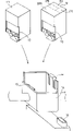
Fig. 4 is an outside drawing of schematically representing a storage box.
Fig. 5 A is an ink gun surface view of schematically representing to have different number spouts respectively with 5B.
Fig. 6 A and 6B are the ink gun surface view of schematically representing to have the different densities spout respectively.
Fig. 7 is an amplification view, expression cap 16.
Fig. 8 A and 8B are the views of schematically representing position relation between the used ink gun of cap pump orifice and monochrome and polychrome respectively.
Below, narrate according to several embodiments of the present invention in conjunction with the accompanying drawings.
Fig. 1 is a view of schematically representing to embody an integral body of the present invention.In Fig. 1, what label 11 was indicated is monochrome ink gun, and it has: form monochrome image and export the spout of ink droplet; The nozzle that links to each other with spout; Shared fluid storage compartment to nozzle supply printing ink; A storage China ink case of possessing specified quantitative printing ink.These parts and ink gun are connected as a single entity and are positioned at wherein.What label 12 was indicated is polychromatic ink gun, and it has: spout, nozzle, a shared fluid storage compartment, the black case of storage, these parts all as the part of monochrome ink gun 11 and ink gun be connected as a single entity and be positioned at wherein; In addition, also install to store the black case of several storages of color ink such as dark blue, yellow, pinkish red, black respectively.For these two ink guns, label 13 indication persons form to supply to drive energy generating element and the electronic signal terminal of usefulness in the jet pipe of output ink droplet; Label 14 indication persons are a supporting and the fixing balladeur train that all is suitable for of monochrome ink gun 11 and polychromatic ink gun 12; Label 15 indication persons provide the electronic signal terminal end surface that main body links to each other with the electronic signal terminal 13 of each ink gun assembly.According to purposes, monochrome ink gun 11 and polychromatic ink gun 12 can exchange, and are installed in separately on the balladeur train 14 respectively then.
Fig. 7 is the detailed section view of cap 16.In Fig. 7, label 71 indication persons are cap rubbers.In Fig. 7, each delivery outlet surface engagement of cap upper end and multiple ink gun.In Fig. 7, because pump orifice portion is positioned at the centre of cap rubber 71, just do not retain the printing ink that is sucked in the cap rubber 71, like this, just can aspirate printing ink equably from the centre and the two ends of nozzle.
Label 72 indication persons are cases of cap, and it is supporting the suction tube 73 of cap rubber 71 and the pump that links to each other with cap rubber 71, and this pipe conductibility ground links to each other with the suction pump (not shown).
When suction pump was aspirated after the delivery outlet surface engagement of cap 16 and monochrome ink gun 11 or polychromatic ink gun 12, suction was just consistent with every kind of shower nozzle and aspirate frequency and negative pressure mode carries out with the best.In other words, for polychromatic ink gun, because the printing ink output quantity is fixed as to lack than the monochrome ink gun output quantity, the nozzle area of output record ink droplet just designs lessly, the imaging surface generation diffusion of coloring matter that is being recorded during blend color in case use polychrome ink jet print head 12.The polychromatic ink gun resistance that printing ink flows in shower nozzle when suction is bigger thus, just need be aspirating the height that frequency or negative pressure are set up more usedly than monochrome ink gun.Therefore, be used for setting up different suction conditions with making of every kind of ink gun.
In addition, for the yellow of containing polychromatic ink gun, magenta, the printing ink diffusion of coloring matter such as dark blue, mix with surfactant in each color ink.Ink gun designs to such an extent that adapt to the high ink ingredient of ratio of viscosities black ink.Therefore, during from the printing ink of every kind of color of delivery outlet area suction of polychromatic ink gun 12, just can aspirate more printing ink with less suction negative pressure or lower frequency, because handy black, yellow, pinkish red, dark blue four color inks of this ink gun design, thereby also comprise the black ink that viscosity is lower.Naturally, suction is got up also than designing to such an extent that only to be used for the ink gun of Huang, magenta, dark blue three color inks easier.But, even if polychromatic ink gun designs handy four kinds of colors, also must set up one be different from only use monochromatic ink gun fixed suction conditions.
Fig. 8 A and 8B are the views that shows an embodiment, and cap inside is wherein aspirated by a suction pump.
Fig. 8 A shows the situation with the single-colour ink-jetting record head.Fig. 8 B shows the situation with the polychrome ink jet print head.
In Fig. 8 A and 8B, when ink jet print head is covered, the pump orifice 161 that serves as this cap of suction pump 81 connectors, shown in Fig. 8 A, just be in a corresponding position, center with single-colour ink-jetting record head delivery outlet zone, shown in Fig. 8 B, then be in one with polychrome ink jet print head black ink delivery outlet zone vis-a-vis but on the position of deflection next-door neighbour's navy blue printing ink output area one side.
Owing to arrange with the location that pump orifice is such, just can be put into the higher printing ink of density than on the position near pump orifice, that is to say, can be the nozzle arrangement of spray black ink in a side of pump orifice, and the nozzle arrangement of color inks such as, Huang dark blue, pinkish red spray is opposite side (these several color of ink density relationship are dark blue>magenta>yellow).
Mode like this, when pump during from pump orifice suction soft ink, printing ink is just taken out that side that occurs to the higher printing ink of density, so just can contain minimum zone to the degree of mixing of every kind of color ink when aspirating.
Fig. 2 A and 2B are respectively the front views of monochrome ink gun 11 and polychromatic ink gun 12, and each component all is to observe from the ink gun surface.In Fig. 2 A and 2B, it is cap 16 joint portions respectively that oblique line marks part, and in fact by the same configuration design.In Fig. 2 A, label 21 indication persons are spout circuits of output black printing ink, 128 spouts that it has the output ink droplet to arrange by 360dpi density.Equally, under the situation of polychromatic ink gun 12, because ink gun inside is divided into four ink colors parts, the spout circuit just is divided into four districts.In the example of Fig. 2 B, label 22 indication persons are output black ink, 64 spouts, density are arranged is the spout circuit of 360dpi; 23 indication persons are the dark blue printing ink of output, 24 spouts, density are arranged is the spout circuit of 360dpi; 24 indication persons are output magenta inks, 24 spouts, density are arranged is the spout circuit of 360dpi; 25 indication persons are output yellow inks, 24 spouts, density are arranged is the spout circuit of 360dpi.
Fig. 3 is the view that shows the printing machine outward appearance.In Fig. 3, label 31 indication persons are according to the printing machine of the present invention by an ink-jet recording apparatus group structure.As shown in Figure 3, monochrome ink gun 11 and polychromatic ink gun 12 are installed in respectively on the printing machine 31 selectively according to purposes.This moment, each member on the printing machine, promptly balladeur train 14, electronic signal terminal end surface 15, cap 16 are connected with several ink guns respectively.Except that said structure, also have a storage box and deposit no ink gun, in case the printing ink that comes out in this record head spout is dry and hard.
Fig. 4 is the view that shows the storage box outward appearance.In Fig. 4, when lid 41 was shut, a cap of forming in this box main body 42 just was engaged with each other with the ink gun surface, in case the printing ink that comes out in this no ink gun spout is dry and hard.
Fig. 5 A and 5B are the views of representing another embodiment.Fig. 5 A and 5B are respectively the ink gun front views of observing from the ink gun surface.Label 51 indication persons among Fig. 5 A, being one, 64 spouts, density are arranged is the spout circuit example of 360dpi; 52 indication persons, being one has 128 spouts, and density is the spout circuit example of 360dpi.All the other all structures are all identical with person noted earlier, still, use the ink gun of these kinds, just can select different recording speed according to purposes, have several ink guns that different spout quantity cause different costs, and finish desired record.
Fig. 6 A and 6B are the views of representing another embodiment.Label 61 indication persons among Fig. 6 A, being one, 128 spouts, density are arranged is the spout circuit example of 360dpi; 62 indication persons, being one, 128 spouts, density are arranged is the spout circuit example of 400dpi.Owing to adorned the ink gun of these kinds, just can select the different ink gun of packing density, and finish desired record according to purposes.
Form at various types of use heat energy the suspension ink droplet with the ink jet print head and tape deck of finishing record in, the present invention can demonstrate premium properties especially.
Consider a kind of like this typical structure and operating principle of method, preferably take to use United States Patent (USP) the 4th, 723, No. 129 and the 4th, 740, the principle that No. 796 specification is illustrated and structure and the principle that can implement.This method is applicable to (on-demand) type register system of what is called " as requested ", also is applicable to the continuation register system.But, this method especially is fit to type as requested, because (its principle is: have at least one to make temperature rise to such an extent that exceed the driving signal of nucleation boiling spread rapidly in the echo message recording process, act on and be contained on liquid (printing ink) sideboard or on the liquid on the fluid path (China ink), make electric transducer produce heat energy so that seethe with excitement at record head thermodynamic-driven part film former, like this, will effectively cause each to drive signal final bubble one by one that forms in record liquid (printing ink).Along with the big and contraction of support of bubble, liquid (printing ink) is just exported by delivery outlet, produces at least one ink droplet.Because the support of bubble is big and contraction can instantaneously be finished, drive preferably pulsed of signal, therefore, liquid (printing ink) is just exported with the quick response of pulse signals.
The pulsed drive signal preferably the specification of No. the 4th, 463,359, United States Patent (USP) and the 4th, 345, No. 262 illustrate the sort of.In this respect, the rate of temperature rise of heating surface is preferably as United States Patent (USP) the 4th, 313, and No. 124 specification is illustrated does good record with preferable states like that.
The structure of record head can be shown in above-mentioned patent specification, and structural design described in those specifications must be combined delivery outlet, fluid passage and electric transducer (linear pattern fluid passage or perpendicular type fluid passage).In addition, the present invention also comprises United States Patent (USP) the 4th, 558, and No. 333 and the 4th, 459, No. 600 specification is illustrated the sort ofly partly is arranged on a structure in the arc area to thermodynamic-driven.
In addition, the present invention also is applicable to 59-123670 number illustrated the sort of structure that a common groove is wherein arranged as the delivery outlet of a plurality of electric transducers of Japan Patent open file effectively, is applicable to 59-138461 number illustrated the sort of structure that absorbs aperture corresponding to the heat energy pressure wave of delivery outlet that wherein forms of Japan Patent open file.
In addition, the full linear record head that the recordable dominant record media width of its length and recording equipment is conformed to, the present invention can show above-mentioned various effects more significantly, and do not need to consider whether to combine illustrated those record heads of above-mentioned each specification or to form single complete record head, make structure satisfy the length of full linear record head.
Also have, no matter record head be can with equipment body by electronic component link to each other replaceable chip-shaped, still store the chuck type that black case and record head itself are integrated, all can effectively adopt the present invention.
In addition, preferably additionally for record head is equipped with restorer and stand-by equipment in advance, as the part of the tape deck that meets various embodiments of the present invention, because these extras can make effect of the present invention more firm.The title that these extras are concrete is: the cap equipment of record head, aforesaid suction restorer; Also have the restorer of applying pressure, such as the heating element heater outside electric transducer or this kind transducer, or the pre-heating device of this class component synthetic parts and so on.Adopt the non-timed to export the way of output in advance of finishing output, also help to realize stable record.
In addition, use the present invention, not only for the recording mode of only using mass-tone such as black, and for in the polychrome mode of different colours printing ink arrive a kind of mode less or with the device of the panchromatic mode of shades of colour printing ink mixing, all extremely effective, several record heads be connected as a single entity the structure or composite construction all like this.
In addition, in above-mentioned each embodiment of the invention, though printing ink is expressed as liquid, it also can be a kind ofly to be lower than room temperature and to be in the just ink material of liquefaction of room temperature with regard to curing.Usually the temperature range that is controlled in 30 ℃ to 70 ℃ owing to printing ink is stablized the usefulness of output with interior to stablize its viscosity confession, and printing ink just can liquefy when available tracer signal is sent.
In addition, actively preventing to use heat energy to cause in temperature raises because of the printing ink proterties is become liquid from solid, or use for anti-its volatilization remain untouched so that dry and hard printing ink in, the printing ink that can adopt a kind of its characteristic to be to use heat energy just can liquefy, the printing ink that for example when applying heat energy, itself can be liquefied as black liquid and can be output according to tracer signal, and begun dry and hard printing ink on the recording medium once having arrived.In the case, can allow printing ink remain in recess in the liquid or solid mode, or allow it pass through each hole as the sort of porous plate as illustrated in Japan Patent open file 54-56847 number or 60-71260 number, so just can make printing ink under retaining facing to electric transducer.In the present invention, for the effective method of above-mentioned various printing ink, be exactly to implement the sort of method of above-mentioned film boiling of using.
In addition, mode as the tape deck that meets various embodiments of the present invention, can adopt a copy device, it is except combined with the image output terminal that is connected as a single entity for the usefulness of word processor, computer or other information processors or be installed separately, also with a reading machine combination, in addition, also can adopt a kind of picture unit pattern with transmission and receiving function.
According to the various embodiments described above, prepare the several ink guns that can on single common carriage, install and remove, from these ink guns, select several ink guns to be installed on the balladeur train then for use.In this way, just can enlarge the image kind scope that can write down.
In addition, the structure owing to by optional equipment places the black output area to the pumping unit of the cap that links to each other with suction pump, just can make the polychrome record head play the suction restitution in the containment blend of colors.
In addition, according to each embodiment of the present invention, make a new ink gun play stable suction restitution with a cap cover part with many nozzles, just can play the suction restitution then to the printing ink mixture of using for second ink gun with higher relatively precipitation density and relatively low precipitation density, this second ink gun also is equipped with some output precisions, each assembly is for the usefulness of the ink emission of different performance, the discharging scope nozzle with first ink gun in fact is identical, like this, just avoid owing to use different caps to carry out contingent bad suction under the situation of suction separately by each output precision respectively.
In addition, in the printing ink that meets single colors such as the yellow of various embodiments of the present invention, magenta, dark blue, black (if printing ink of these colors only for minimum several output precisions with being enough good), black ink relatively easily aspirates, and color ink such as yellow, pinkish red, dark blue is not easy suction relatively.Yet, even when the performance of these printing ink reversed, the present invention also can be suitable for, and in other words, especially aspirated under the situation of this ink gun with a cap then for the different printing ink of various performances has prepared a kind of ink gun in a kind of structure, the present invention can be effectively suitable.In addition, monochrome ink gun quantity of ink single when suction recovers is very big, wants to recover suction, also without a doubt.
In various embodiments of the present invention, " ink performance " comprise the different qualities that printing ink moves in the printing ink emptying path that recovers to install for suction (as the viscosity of printing ink, since the surface tightly the precipitation that causes of power be inclined to).The meaning of " different ink performances " is meant that having a kind of in these characteristics at least is this situation inequality.
In addition, according to various embodiments of the present invention, it is shared and can make the supported and fixing balladeur train of each ink gun, have different injector spacings and export in other words that the various ink guns of monochrome or polychrome printing ink, one are being connected the record ink droplet output face of the electric connecting element of each ink gun electronic signal terminal end surface, shared each ink gun of covering and then for replacing the single cap of each ink gun for the purpose of writing down, just can obtain following effect to be equipped with single the ink gun for the different number nozzles of various bands:
1. can the scope that form image be widened according to purposes;
2. thereby can unify required each parts of main body provides a cover cost minimum device;
3. thereby can unify required each parts of main body makes this device volume littler.
Also have, according to various embodiments of the present invention, make printing ink be discharged into the pump orifice that goes the pump from delivery outlet, institute's holding position is near the black ink delivery outlet.In the case, when each color ink should aspirate with black ink, just can make the mixing of each color ink contain Min..Thus, just can reduce making printing ink from ink pathway, emit needed discharge capacity in advance,, will reduce the operating cost of device so effectively so that before record, the printing ink of each mixture of colours is mixed in the ink pathway will recover color mixture the time.
Claims (14)
1. method of recovering ink-jet recording apparatus, this tape deck carries out record by first ink jet print head (12) and second ink jet print head of selecting to install (11), and described method is characterised in that, may further comprise the steps:
Assemble a balladeur train (14), it supports described first ink jet print head (12) selectively, and it is equiped with the first printing ink output area (22) in order to the printing ink of exporting easy precipitation and support described second ink jet print head (11) it is equipped with a printing ink output area (21);
Assemble whole printing ink output area (22,23,24,25, the 21) cap cover parts (16) that can cover described first and second ink jet print heads (12,11); And
Assemble the aspirating mechanism (81) that retains printing ink in the above-mentioned cap cover part of suction (16); Described aspirating mechanism has a connected entrance (161), it makes described aspirating mechanism be connected with described cap cover part, and dress up in such scope, it is in the face of the first printing ink output area (22) and be partial to the described second printing ink output area (23,24,25), perhaps face the printing ink output area (21) of described second ink jet print head (11).
2. the method for claim 1, it is characterized in that, wherein said balladeur train (14) supports the single-colour ink-jetting record head (11) of an output black printing ink selectively, with one be equipped with by the output area by yellow, pinkish red, dark blue and the tactic polychrome ink jet print head of black ink (12), described aspirating mechanism connected component (161) is in the face of the central area of the output oral region (BK) of described single-colour ink-jetting record head (11), in the scope in the mass colour printing ink delivery outlet zone (BK) of facing polychrome ink jet print head (12), navy blue printing ink delivery outlet zone (C) side is partial in the position of facing simultaneously.
3. ink-jet recording apparatus by the first nozzle record head (12) and second ink jet print head (11) being installed selectively so that carry out record, is characterized in that described ink-jet recording apparatus comprises:
A balladeur train (14) is used for selecting supporting described first ink jet print head (12), it is provided with the printing ink and the second printing ink output area (23 that the first printing ink output area (22) is used to export easy precipitation, 24,25) printing ink that is difficult to precipitate in order to output, described second ink jet print head (11) is equipped with printing ink output area (21);
A kind of cap cover part (16) that can cover the whole described printing ink output area (22,23,24,25,21) of above-mentioned each first and second ink jet print head (12,11); And
Retain the aspirating mechanism (81) of printing ink in a kind of above-mentioned cap cover part of suction (16), this aspirating mechanism has an aspirating mechanism connected entrance (161), it makes the beastly parts of described aspirating mechanism and the above-mentioned cap company of leading mutually, and be assembled in such scope, face the first printing ink output area (22) and be partial to the described second printing ink output area (23,24,25), perhaps face the printing ink output area (21) of described second ink jet print head (11).
4. the method for claim 1 is characterized in that, the ink viscosity by the described second printing ink output area (23,24,25) output is higher than the ink viscosity of exporting by the described first printing ink output area (22) of institute.
5. the method for claim 1 is characterized in that, is higher than the ink density of being exported by the described second printing ink output area (23,24,25) by the defeated ink density in the described first printing ink output area (22).
6. device as claimed in claim 3 is characterized in that, described first ink jet print head (12) is more than the printing ink nozzle of described second ink jet print head (11) assembling.
7. device as claimed in claim 3 is characterized in that, described ink jet print head (11; 12) be the single-colour ink-jetting record head (11) of a kind of output black printing ink or a kind of to be furnished with respectively output yellow, the polychrome ink jet print head (12) of the delivery outlet of pinkish red dark blue and black ink, described record head is bearing on the described balladeur train (14) selectively.
8. ink-jet recording apparatus as claimed in claim 7, wherein different ink jet print head (11,12) has the printing ink delivery outlet of different numbers.
9. ink-jet recording apparatus as claimed in claim 7, wherein said have the printing ink delivery outlet of selecting to be bearing in the different ink jet print heads on the described balladeur train that different spacing is arranged.
10. as a described ink discharge device in the claim 7 to 9, wherein said polychrome ink jet print head (12) is equipped with printing ink output oral region and exports yellow, magenta, dark blue and black ink in order.
11., wherein having nothing in common with each other aspect the precipitation trend of yellow, magenta, navy blue and black ink by the ink performance of ink jet print head printing ink output area as a described ink-jet recording apparatus in the claim 7 to 10.
12. as a described ink-jet recording apparatus in the claim 7 to 11, wherein said aspirating mechanism interconnecting part is configured to the central area in the face of the delivery outlet zone (BK) of described yellow ink jet print head (11), simultaneously, also in the face of position like this, promptly deflection navy blue printing ink is exported oral region (C) in the zone of the black ink output area (BK) of facing described polychrome ink jet print head (12).
13. as ink-jet recording apparatus as described in the claim 3 to 12, wherein each has the different ink jet print heads of selecting to be bearing on the described balladeur train (14) (11,12) be furnished with electric transducer,, make by printing ink delivery outlet output printing ink by adopting by described electric transducer.
14. as ink-jet recording apparatus as described in the claim 3 to 13, wherein said ink-jet recording apparatus forms image according to the different recording mode that conforms to the selected above-mentioned different ink guns that are bearing on the described balladeur train on recording medium.
Applications Claiming Priority (6)
| Application Number | Priority Date | Filing Date | Title |
|---|---|---|---|
| JP6592/1994 | 1994-01-25 | ||
| JP6592/94 | 1994-01-25 | ||
| JP659294 | 1994-01-25 | ||
| JP20253494A JP3190211B2 (en) | 1994-01-25 | 1994-08-26 | Ink jet recording apparatus capable of selectively mounting different ink jet recording heads and head recovery method thereof |
| JP202534/94 | 1994-08-26 | ||
| JP202534/1994 | 1994-08-26 |
Publications (2)
| Publication Number | Publication Date |
|---|---|
| CN1115719A CN1115719A (en) | 1996-01-31 |
| CN1066103C true CN1066103C (en) | 2001-05-23 |
Family
ID=26340781
Family Applications (1)
| Application Number | Title | Priority Date | Filing Date |
|---|---|---|---|
| CN95101472A Expired - Fee Related CN1066103C (en) | 1994-01-25 | 1995-01-25 | Ink jet recording apparatus and method for recovering an ink jet recording head used for such apparatus |
Country Status (5)
| Country | Link |
|---|---|
| US (1) | US5831645A (en) |
| EP (1) | EP0664216B1 (en) |
| JP (1) | JP3190211B2 (en) |
| CN (1) | CN1066103C (en) |
| DE (1) | DE69516429T2 (en) |
Families Citing this family (10)
| Publication number | Priority date | Publication date | Assignee | Title |
|---|---|---|---|---|
| JP3303003B2 (en) * | 1995-09-21 | 2002-07-15 | 富士写真フイルム株式会社 | Ink jet recording device |
| JP3581605B2 (en) | 1998-10-27 | 2004-10-27 | キヤノン株式会社 | INK SET, INKJET RECORDING METHOD, RECORDING UNIT, INK CARTRIDGE, INKJET RECORDING APPARATUS, AND METHOD FOR MITIGATION OF SOLID PRODUCTION IN COMMONARY RECOVERY SYSTEM |
| US6520618B2 (en) * | 2000-02-24 | 2003-02-18 | Canon Kabushiki Kaisha | Pump, device for recovering liquid ejection and image forming apparatus equipped with the pump |
| DE60220000T2 (en) * | 2001-09-06 | 2008-01-10 | Canon K.K. | Ink jet recording apparatus |
| TWI242663B (en) * | 2002-07-09 | 2005-11-01 | Seiko Epson Corp | Jetting method of liquid, jetting apparatus of liquid, production method of substrate for electro-optical apparatus and production method of electro-optical apparatus |
| GB2447919B (en) * | 2007-03-27 | 2012-04-04 | Linx Printing Tech | Ink jet printing |
| EP2082879B2 (en) * | 2008-01-28 | 2020-02-12 | Hitachi Industrial Equipment Systems Co., Ltd. | Ink jet recording device |
| JP5233595B2 (en) | 2008-10-31 | 2013-07-10 | 株式会社リコー | Image forming apparatus and image forming apparatus assembly system |
| JP5463883B2 (en) * | 2009-12-03 | 2014-04-09 | 株式会社リコー | Image forming apparatus |
| KR101671918B1 (en) | 2014-10-10 | 2016-11-03 | 신화인터텍 주식회사 | Transparent conductive film and method of fabricating the same |
Citations (3)
| Publication number | Priority date | Publication date | Assignee | Title |
|---|---|---|---|---|
| EP0446885A1 (en) * | 1990-03-14 | 1991-09-18 | Canon Kabushiki Kaisha | Ink jet recording apparatus and mechanism for discharging maintenance and recovery provided for the apparatus |
| EP0551752A2 (en) * | 1991-12-19 | 1993-07-21 | Canon Kabushiki Kaisha | Method of controlling an ink-jet recording apparatus according to recording head information, and ink-jet recording apparatus in which the method is implemented |
| EP0580421A2 (en) * | 1992-07-24 | 1994-01-26 | Canon Kabushiki Kaisha | Liquid jetting apparatus and method |
Family Cites Families (16)
| Publication number | Priority date | Publication date | Assignee | Title |
|---|---|---|---|---|
| CA1127227A (en) * | 1977-10-03 | 1982-07-06 | Ichiro Endo | Liquid jet recording process and apparatus therefor |
| JPS5936879B2 (en) * | 1977-10-14 | 1984-09-06 | キヤノン株式会社 | Thermal transfer recording medium |
| US4330787A (en) * | 1978-10-31 | 1982-05-18 | Canon Kabushiki Kaisha | Liquid jet recording device |
| US4345262A (en) * | 1979-02-19 | 1982-08-17 | Canon Kabushiki Kaisha | Ink jet recording method |
| US4463359A (en) * | 1979-04-02 | 1984-07-31 | Canon Kabushiki Kaisha | Droplet generating method and apparatus thereof |
| US4313124A (en) * | 1979-05-18 | 1982-01-26 | Canon Kabushiki Kaisha | Liquid jet recording process and liquid jet recording head |
| US4558333A (en) * | 1981-07-09 | 1985-12-10 | Canon Kabushiki Kaisha | Liquid jet recording head |
| JPS59123670A (en) * | 1982-12-28 | 1984-07-17 | Canon Inc | Ink jet head |
| JPS59138461A (en) * | 1983-01-28 | 1984-08-08 | Canon Inc | Liquid jet recording apparatus |
| JPS6071260A (en) * | 1983-09-28 | 1985-04-23 | Erumu:Kk | Recorder |
| US4728968A (en) * | 1985-08-30 | 1988-03-01 | Siemens Aktiengesellschaft | Arrangement of discharge openings in a printhead of a multi-color ink printer |
| JPS62279954A (en) * | 1986-05-29 | 1987-12-04 | Canon Inc | Ink jet recording method |
| JPH0825283B2 (en) * | 1986-12-25 | 1996-03-13 | キヤノン株式会社 | Inkjet device recovery method |
| US4908638A (en) * | 1988-12-15 | 1990-03-13 | Xerox Corporation | Ink jet marking head having multicolor capability |
| DE69026360D1 (en) * | 1989-12-29 | 1996-05-09 | Canon Kk | Suction recovery device and color beam recorder provided with it |
| JP3187607B2 (en) * | 1993-05-25 | 2001-07-11 | キヤノン株式会社 | Ink jet recording device |
-
1994
- 1994-08-26 JP JP20253494A patent/JP3190211B2/en not_active Expired - Fee Related
-
1995
- 1995-01-23 US US08/377,110 patent/US5831645A/en not_active Expired - Fee Related
- 1995-01-24 DE DE69516429T patent/DE69516429T2/en not_active Expired - Fee Related
- 1995-01-24 EP EP95100906A patent/EP0664216B1/en not_active Expired - Lifetime
- 1995-01-25 CN CN95101472A patent/CN1066103C/en not_active Expired - Fee Related
Patent Citations (3)
| Publication number | Priority date | Publication date | Assignee | Title |
|---|---|---|---|---|
| EP0446885A1 (en) * | 1990-03-14 | 1991-09-18 | Canon Kabushiki Kaisha | Ink jet recording apparatus and mechanism for discharging maintenance and recovery provided for the apparatus |
| EP0551752A2 (en) * | 1991-12-19 | 1993-07-21 | Canon Kabushiki Kaisha | Method of controlling an ink-jet recording apparatus according to recording head information, and ink-jet recording apparatus in which the method is implemented |
| EP0580421A2 (en) * | 1992-07-24 | 1994-01-26 | Canon Kabushiki Kaisha | Liquid jetting apparatus and method |
Also Published As
| Publication number | Publication date |
|---|---|
| EP0664216A3 (en) | 1995-11-15 |
| JPH07251511A (en) | 1995-10-03 |
| EP0664216A2 (en) | 1995-07-26 |
| DE69516429T2 (en) | 2000-10-19 |
| US5831645A (en) | 1998-11-03 |
| EP0664216B1 (en) | 2000-04-26 |
| JP3190211B2 (en) | 2001-07-23 |
| DE69516429D1 (en) | 2000-05-31 |
| CN1115719A (en) | 1996-01-31 |
Similar Documents
| Publication | Publication Date | Title |
|---|---|---|
| CN1071194C (en) | Ink supply mechanism, ink jet cartridge provided with such a mechanism, and ink jet recording apparatus provided with such a mechanism | |
| US6557984B2 (en) | Ink-jet printing head and ink-jet printing apparatus | |
| US5504508A (en) | Ink receiving cap, and ink-jet recording apparatus and ink discharging method using the same | |
| CN1066103C (en) | Ink jet recording apparatus and method for recovering an ink jet recording head used for such apparatus | |
| DE69126900T2 (en) | Inkjet device | |
| CN1251875C (en) | Ink container, record head and corresponding recording device | |
| US6637874B2 (en) | Liquid ejecting head, suction recovering method, head cartridge and image forming apparatus | |
| EP0785072A2 (en) | An ink-jet head, an ink-jet-head cartridge, an ink-jet apparatus and an ink-jet recording method used in gradation recording | |
| JP2003519030A (en) | Ink jet print cartridge and method of manufacturing the same | |
| JP2002506759A (en) | A modular approach for inkjet technology | |
| CN1872557A (en) | Nozzle face cleaning method | |
| CN1087230C (en) | Ink jet recording apparatus and ink tank used for the ink jet recording apparatus | |
| DE69420895T2 (en) | Ink jet head, ink jet device, and method for performing a recovery operation of the device | |
| JP3209930B2 (en) | Ink jet printing apparatus, ink jet printing method, and data creation method | |
| JP3105364B2 (en) | Ink jet recording head and ink jet recording apparatus | |
| US8336989B2 (en) | Ink jet recording apparatus | |
| JPS5812764A (en) | Ink jet recording system | |
| JPH03142249A (en) | Multicolor ink-jet apparatus | |
| JPH1076648A (en) | Ink jet recording head and ink jet recording method | |
| JP4280502B2 (en) | Recording apparatus and recording method | |
| JPH0858095A (en) | Ink jet cartridge and ink jet recording device | |
| JPH0789095A (en) | Ink jet recorder | |
| JP2004167930A (en) | Inkjet recording head and device |
Legal Events
| Date | Code | Title | Description |
|---|---|---|---|
| C10 | Entry into substantive examination | ||
| SE01 | Entry into force of request for substantive examination | ||
| C06 | Publication | ||
| PB01 | Publication | ||
| C14 | Grant of patent or utility model | ||
| GR01 | Patent grant | ||
| C19 | Lapse of patent right due to non-payment of the annual fee | ||
| CF01 | Termination of patent right due to non-payment of annual fee |