CN106537848B - Wireless communication system - Google Patents
Wireless communication system Download PDFInfo
- Publication number
- CN106537848B CN106537848B CN201580023495.2A CN201580023495A CN106537848B CN 106537848 B CN106537848 B CN 106537848B CN 201580023495 A CN201580023495 A CN 201580023495A CN 106537848 B CN106537848 B CN 106537848B
- Authority
- CN
- China
- Prior art keywords
- wireless
- node
- service
- slave
- devices
- Prior art date
- Legal status (The legal status is an assumption and is not a legal conclusion. Google has not performed a legal analysis and makes no representation as to the accuracy of the status listed.)
- Active
Links
Images


Classifications
-
- H—ELECTRICITY
- H04—ELECTRIC COMMUNICATION TECHNIQUE
- H04M—TELEPHONIC COMMUNICATION
- H04M1/00—Substation equipment, e.g. for use by subscribers
- H04M1/72—Mobile telephones; Cordless telephones, i.e. devices for establishing wireless links to base stations without route selection
- H04M1/724—User interfaces specially adapted for cordless or mobile telephones
- H04M1/72403—User interfaces specially adapted for cordless or mobile telephones with means for local support of applications that increase the functionality
- H04M1/72409—User interfaces specially adapted for cordless or mobile telephones with means for local support of applications that increase the functionality by interfacing with external accessories
- H04M1/72412—User interfaces specially adapted for cordless or mobile telephones with means for local support of applications that increase the functionality by interfacing with external accessories using two-way short-range wireless interfaces
-
- H—ELECTRICITY
- H04—ELECTRIC COMMUNICATION TECHNIQUE
- H04L—TRANSMISSION OF DIGITAL INFORMATION, e.g. TELEGRAPHIC COMMUNICATION
- H04L12/00—Data switching networks
- H04L12/28—Data switching networks characterised by path configuration, e.g. LAN [Local Area Networks] or WAN [Wide Area Networks]
- H04L12/2803—Home automation networks
- H04L12/2807—Exchanging configuration information on appliance services in a home automation network
- H04L12/2809—Exchanging configuration information on appliance services in a home automation network indicating that an appliance service is present in a home automation network
-
- H—ELECTRICITY
- H04—ELECTRIC COMMUNICATION TECHNIQUE
- H04L—TRANSMISSION OF DIGITAL INFORMATION, e.g. TELEGRAPHIC COMMUNICATION
- H04L12/00—Data switching networks
- H04L12/28—Data switching networks characterised by path configuration, e.g. LAN [Local Area Networks] or WAN [Wide Area Networks]
- H04L12/2803—Home automation networks
- H04L12/2807—Exchanging configuration information on appliance services in a home automation network
- H04L12/2812—Exchanging configuration information on appliance services in a home automation network describing content present in a home automation network, e.g. audio video content
-
- H—ELECTRICITY
- H04—ELECTRIC COMMUNICATION TECHNIQUE
- H04L—TRANSMISSION OF DIGITAL INFORMATION, e.g. TELEGRAPHIC COMMUNICATION
- H04L12/00—Data switching networks
- H04L12/28—Data switching networks characterised by path configuration, e.g. LAN [Local Area Networks] or WAN [Wide Area Networks]
- H04L12/2803—Home automation networks
- H04L12/2807—Exchanging configuration information on appliance services in a home automation network
- H04L12/2814—Exchanging control software or macros for controlling appliance services in a home automation network
-
- H—ELECTRICITY
- H04—ELECTRIC COMMUNICATION TECHNIQUE
- H04M—TELEPHONIC COMMUNICATION
- H04M1/00—Substation equipment, e.g. for use by subscribers
- H04M1/72—Mobile telephones; Cordless telephones, i.e. devices for establishing wireless links to base stations without route selection
- H04M1/724—User interfaces specially adapted for cordless or mobile telephones
- H04M1/72403—User interfaces specially adapted for cordless or mobile telephones with means for local support of applications that increase the functionality
- H04M1/72409—User interfaces specially adapted for cordless or mobile telephones with means for local support of applications that increase the functionality by interfacing with external accessories
- H04M1/72415—User interfaces specially adapted for cordless or mobile telephones with means for local support of applications that increase the functionality by interfacing with external accessories for remote control of appliances
-
- H—ELECTRICITY
- H04—ELECTRIC COMMUNICATION TECHNIQUE
- H04N—PICTORIAL COMMUNICATION, e.g. TELEVISION
- H04N21/00—Selective content distribution, e.g. interactive television or video on demand [VOD]
- H04N21/40—Client devices specifically adapted for the reception of or interaction with content, e.g. set-top-box [STB]; Operations thereof
- H04N21/41—Structure of client; Structure of client peripherals
- H04N21/4104—Peripherals receiving signals from specially adapted client devices
- H04N21/4126—The peripheral being portable, e.g. PDAs or mobile phones
-
- H—ELECTRICITY
- H04—ELECTRIC COMMUNICATION TECHNIQUE
- H04N—PICTORIAL COMMUNICATION, e.g. TELEVISION
- H04N21/00—Selective content distribution, e.g. interactive television or video on demand [VOD]
- H04N21/40—Client devices specifically adapted for the reception of or interaction with content, e.g. set-top-box [STB]; Operations thereof
- H04N21/41—Structure of client; Structure of client peripherals
- H04N21/414—Specialised client platforms, e.g. receiver in car or embedded in a mobile appliance
- H04N21/41407—Specialised client platforms, e.g. receiver in car or embedded in a mobile appliance embedded in a portable device, e.g. video client on a mobile phone, PDA, laptop
-
- G—PHYSICS
- G06—COMPUTING; CALCULATING OR COUNTING
- G06F—ELECTRIC DIGITAL DATA PROCESSING
- G06F3/00—Input arrangements for transferring data to be processed into a form capable of being handled by the computer; Output arrangements for transferring data from processing unit to output unit, e.g. interface arrangements
- G06F3/01—Input arrangements or combined input and output arrangements for interaction between user and computer
- G06F3/048—Interaction techniques based on graphical user interfaces [GUI]
- G06F3/0481—Interaction techniques based on graphical user interfaces [GUI] based on specific properties of the displayed interaction object or a metaphor-based environment, e.g. interaction with desktop elements like windows or icons, or assisted by a cursor's changing behaviour or appearance
- G06F3/04817—Interaction techniques based on graphical user interfaces [GUI] based on specific properties of the displayed interaction object or a metaphor-based environment, e.g. interaction with desktop elements like windows or icons, or assisted by a cursor's changing behaviour or appearance using icons
-
- G—PHYSICS
- G06—COMPUTING; CALCULATING OR COUNTING
- G06F—ELECTRIC DIGITAL DATA PROCESSING
- G06F3/00—Input arrangements for transferring data to be processed into a form capable of being handled by the computer; Output arrangements for transferring data from processing unit to output unit, e.g. interface arrangements
- G06F3/01—Input arrangements or combined input and output arrangements for interaction between user and computer
- G06F3/048—Interaction techniques based on graphical user interfaces [GUI]
- G06F3/0481—Interaction techniques based on graphical user interfaces [GUI] based on specific properties of the displayed interaction object or a metaphor-based environment, e.g. interaction with desktop elements like windows or icons, or assisted by a cursor's changing behaviour or appearance
- G06F3/0482—Interaction with lists of selectable items, e.g. menus
-
- G—PHYSICS
- G06—COMPUTING; CALCULATING OR COUNTING
- G06T—IMAGE DATA PROCESSING OR GENERATION, IN GENERAL
- G06T11/00—2D [Two Dimensional] image generation
- G06T11/20—Drawing from basic elements, e.g. lines or circles
- G06T11/203—Drawing of straight lines or curves
-
- H—ELECTRICITY
- H04—ELECTRIC COMMUNICATION TECHNIQUE
- H04M—TELEPHONIC COMMUNICATION
- H04M2250/00—Details of telephonic subscriber devices
- H04M2250/06—Details of telephonic subscriber devices including a wireless LAN interface
-
- H—ELECTRICITY
- H04—ELECTRIC COMMUNICATION TECHNIQUE
- H04N—PICTORIAL COMMUNICATION, e.g. TELEVISION
- H04N21/00—Selective content distribution, e.g. interactive television or video on demand [VOD]
- H04N21/40—Client devices specifically adapted for the reception of or interaction with content, e.g. set-top-box [STB]; Operations thereof
- H04N21/43—Processing of content or additional data, e.g. demultiplexing additional data from a digital video stream; Elementary client operations, e.g. monitoring of home network or synchronising decoder's clock; Client middleware
- H04N21/436—Interfacing a local distribution network, e.g. communicating with another STB or one or more peripheral devices inside the home
- H04N21/43615—Interfacing a Home Network, e.g. for connecting the client to a plurality of peripherals
-
- H—ELECTRICITY
- H04—ELECTRIC COMMUNICATION TECHNIQUE
- H04N—PICTORIAL COMMUNICATION, e.g. TELEVISION
- H04N21/00—Selective content distribution, e.g. interactive television or video on demand [VOD]
- H04N21/40—Client devices specifically adapted for the reception of or interaction with content, e.g. set-top-box [STB]; Operations thereof
- H04N21/47—End-user applications
-
- H—ELECTRICITY
- H04—ELECTRIC COMMUNICATION TECHNIQUE
- H04W—WIRELESS COMMUNICATION NETWORKS
- H04W84/00—Network topologies
- H04W84/02—Hierarchically pre-organised networks, e.g. paging networks, cellular networks, WLAN [Wireless Local Area Network] or WLL [Wireless Local Loop]
- H04W84/10—Small scale networks; Flat hierarchical networks
- H04W84/12—WLAN [Wireless Local Area Networks]
Abstract
The slave device provides services to the master device via wireless communication, e.g., via wireless docking. The master device has a graphical user interface arranged to generate a system image (400) to show node elements (310, 311, 320) that graphically represent devices and services on, for example, a touch screen. The user may draw a line (410, 420) between selected node elements on the touch screen, causing a line drawing input to be detected. The slave device now initiates a setup operation between the selected devices corresponding to the selected node elements. Subsequently, a setup operation is performed by establishing a wireless connection between the selected devices. Advantageously, the user intuitively commands the wireless connection to be set up in order to use the service via wireless communication.
Description
Technical Field
The invention relates to a wireless communication system comprising at least two wireless devices including a master device providing a master function and a slave device providing a slave function. The slave device is for providing at least one service and the master device is arranged to use the service. The slave device and the master device are arranged to provision services via wireless communication. Wherein each device comprises a communication unit for wireless communication and a processor coupled with the communication unit and arranged for said provisioning service.
The slave device may have one or more built-in peripherals and/or may be arranged to be coupled to at least one external peripheral in order to constitute a wireless docking environment. Providing the service may include providing the master device with access to the respective peripheral device.
The invention also relates to a computer program product, a wireless device method and a wireless device for wireless communication between a slave device and a master device.
Background
The present invention relates to wireless communications, e.g., via Wi-Fi, and more particularly to provisioning a master device with services of a wireless slave device, e.g., providing for use of one or more peripheral devices. In this context, the peripheral device may be an external apparatus such as a display, a keyboard or a mouse, or a peripheral device built in a slave apparatus such as a speaker or a storage unit. For example, the TV may also be a slave device, i.e. a slave function is built into the TV in connection with a number of peripheral devices inside or outside the TV. Any other internal or external resource that accesses and/or uses such peripherals and/or slaves may be referred to as a service provided by the slave.
For example, Wi-Fi (as described in IEEE 802.11) based wireless devices may offer all kinds of services. These may be services such as video rendering, audio rendering, printing, using a USB device (such as a keyboard or mouse), etc. over Wi-Fi. Wi-Fi devices may "advertise" these services on Wi-Fi, enabling other devices to utilize the Wi-Fi radio to see what Wi-Fi services are available in their vicinity. A Wi-Fi device may also query ("probe") another Wi-Fi device as to which Wi-Fi services it must offer. Wi-Fi offers various ways to do such pre-association discovery.
Wireless docking in a wireless communication system having a plurality of wireless devices including a master device providing master functionality and a slave device providing slave functionality may be based on using a Wi-Fi based wireless docking station. Slave functionality may be embedded in a wireless docking station (also known as a wireless docking host or WDH) that enables a mobile device (known as a master or MD) to access a set of peripherals either attached locally by wires or connected wirelessly to a slave device (e.g., USB mouse, HDMI display, bluetooth headset) through a set of general message exchange protocols over a wireless link (e.g., Wi-Fi). A slave device coupled with one or more wired or wireless peripherals is referred to as a wireless docking environment. The slave device may also be another mobile device having one or more available services for the master device. Thus, wireless docking is known, for example, from WO 2012/117306a 1.
The wireless slave device may provide information about its presence through a Wi-Fi beacon, which the master device may use to select and initiate a connection with the selected slave device.
US2006/0258289 describes a wireless media player and related system. The media player may be wirelessly connected to other devices in the system. A list of devices may be shown on the display to enable the user to select the device to connect to. Upon connection, the display may indicate the currently connected device by an icon or text.
EP 2521372 describes the use of Near Field Communication (NFC) for enabling remote control of electronic devices. The mobile device is located within NFC range of the first external device (so-called tagging) to receive the first device information via NFC. The mobile device then communicates with the second external device to transmit the first device information, which may enable a connection between the second external device and the first external device. Further, the mobile device may remotely control the second external device.
Disclosure of Invention
A user of a Wi-Fi device may select a device offering one or more services from a list of devices discovered within range and may attempt to connect with it in order to use the one or more services. Since the range of Wi-Fi signals can reach tens of meters away, a significant number of devices offering Wi-Fi services can be discovered within Wi-Fi range. The user may participate in selecting the correct device/service to connect to. However, understanding and recognizing the connection options between multiple devices and/or services available to a user can be difficult. The user of the master device may be presented with a list of available slave devices and a list of available services for each slave device. Selecting one of the slave devices and/or related services can be complicated. Furthermore, the role of the device, i.e. master or slave, is not always clear, since the device may be able to perform multiple roles (sequentially or concurrently).
It is an object of the present invention to provide a system for wireless communication that enables setting up a connection and acquiring a service while reducing the complexity of user interaction and the time required.
For this purpose, according to a first aspect of the invention, a wireless communication system as claimed in claim 1 is provided, in which system a first device of the at least two wireless devices comprises a graphical user interface comprising a display, an interaction element for receiving user input, and a graphical control unit coupled to the display and the interaction element. The graphics control unit is arranged to: generating a system image to show at least three node elements, each node element graphically representing one of a master device, a slave device, or at least one service, and connection elements between the node elements, each connection element graphically representing a wireless connection or service session established between the node elements, the at least three node elements including a first node element representing a first device; selecting a device to connect by receiving, via an interactive element, a line drawing input indicating a line drawn by a user in a system image between two selected node elements of the at least three node elements; and, upon receiving the line drawing input, initiating a setup operation for a wireless connection or service session between the selected devices corresponding to the selected node elements. The processor is arranged to subsequently perform a setup operation by establishing a wireless connection or service session between the selected devices.
For this purpose a wireless device for use as a first device in the above system is provided as claimed in claim 4, the wireless device comprising a graphical user interface comprising a display, an interaction element for receiving user input, and a graphical control unit coupled to the display and the interaction element.
For this purpose, a method of initiating wireless communication as claimed in claim 14 is provided for use in a wireless device as the first device in the above system.
The measures have the effect that in a wireless communication system, the provisioning service is set up as follows, for example during a docking procedure. A user of a wireless device (e.g., a mobile phone or tablet) interacts with his graphical user interface. The graphical user interface has, for example, a high-resolution touch screen built into the mobile device, or a separate display and mouse, constituting the display and the interactive elements. A system image is generated on the display to show a plurality (i.e., at least three) of symbols or icons as node elements, each graphically representing a wireless device or wireless service. A wireless service may be a function performed by the wireless device itself or a peripheral may be made available via the wireless device, so selecting a node element effectively results in selecting the device it represents or the device providing the service. The system image may also show connection elements, such as lines or other graphical representations of wireless connections that have been established between node elements. Thus, the system image is a graphical overview showing a multitude of selectable node elements, each representing a device or service. Then, in order to select two devices to be connected, a line drawing input is received via the interactive element, as the user draws a line on the display between the two device or service icons, i.e. indicating the line drawn by the user in the system image between the selected node elements. Such lines are drawn manually and therefore need not be straight or actually come from the exact position of the node element, but can be aligned (snap) to such a position or straightened by the graphical unit. Upon receiving a line drawing input, a setup operation between two selected devices corresponding to the selected node elements is initiated. Subsequently, a setup operation is performed by establishing a wireless connection between the selected devices, after which a corresponding session is set up in order to use the selected service. Advantageously, by graphically drawing a line between a master device and a respective slave device or service provided by a slave device, a user is enabled to intuitively select a slave device. So, by the user drawing the line connecting to the icon of the master device (which is typically the user's portable device), it is automatically determined that the master device needs the services of the slave device. Drawing a line between the icons of the master and slave devices may indicate that all services of the slave device to be selected for use are selected, whereas drawing a line between the master and one or more icons of the slave device may indicate that only a subset of all services offered by the slave device are selected. The master and slave now directly participate in the connection or docking because the setup operation identifies both the master and slave or the service. Thus, due to the visual image and interaction of drawing the lines, the user realizes a straightforward and simple way of setting up the required link to the service.
Optionally, in the above wireless communication system, the at least one service comprises accessing and using at least one of: a peripheral device externally coupled with the slave device; an internal resource of the slave device; a network connected to the slave device. Advantageously, in practice, such peripherals or resources of the slave device or the host device are made available to the master device or the docked device.
Optionally, in the above wireless communication system, a second device of the at least two wireless devices comprises a display, and the graphics control unit in the first device is arranged to transmit the generated system image to the second wireless device, and the second wireless device is arranged to receive the generated system image and to display the generated system image via the display. Advantageously, the second device is enabled to display the system image without gathering the required information about the wireless device and service. The user of the second device can now consult or actually control the connection by manipulating the corresponding interaction element, like a mouse or a touch screen. Subsequently, a corresponding setup operation is generated and may be automatically executed by a processor of the second device cooperating with the first device.
Optionally, in the wireless device for use above in a wireless communication system, the graphics control unit is arranged to: receiving, via the interactive element, a line wipe input indicating removal of a connection element between selected node elements in the system image by a user, and, upon receiving the line wipe input, initiating a teardown operation identifying the selected node elements and existing connections, and the processor being arranged to perform the teardown operation by tearing down existing connections or service sessions between the selected node elements. For example, the graphical user interface may show an eraser icon, which may be moved via the interactive element in order to erase an existing connection. Advantageously, the user is enabled to intuitively instruct the wireless communication system to end use of the service and tear down the connection or service session.
Optionally, in the above wireless device for use in a wireless communication system, the graphics control unit is arranged to select the master or slave function by receiving, via the interactive element, a line direction input indicating an origin node at which a line drawn by the user in the system image starts and/or a destination node at which a line drawn by the user in the system image ends, and the processor is arranged to, upon receiving the line direction input, execute the master function if the device corresponds to the origin node and/or execute the slave function if the device corresponds to the destination node. When the user draws the line via the interactive elements, naturally one of the node elements will be connected first, and then the other node element. Therefore, the direction of the line is established by the user drawing action and derived by the graphical control unit as a separate line direction input, while the original node and the destination node are identified. It should be noted that initially, a wireless device may not act in a master or slave role. Advantageously, the master function and/or the slave function is now selected and assigned to the respective device automatically based on the line direction input. The user intuitively selects the master/slave function by drawing a line in the selected direction. In an equivalent embodiment, i.e. the roles may be selected inversely based on the line direction input, the slave function is performed if the device corresponds to the original node and/or the master function is performed if the device corresponds to the destination node.
Optionally, in the above wireless device for use in a wireless communication system, the graphics control unit is arranged to select the master or slave function by receiving a direction reversal input via the interaction element as a line direction input indicating a drawn line from a pre-existing connected pre-existing destination node to a pre-existing origin node, and the processor is arranged to, upon receiving the line direction input, change the master function of the pre-existing origin node to the slave function if the device corresponds to the pre-existing origin node and/or change the slave function of the pre-existing destination node to the master function if the device corresponds to the pre-existing destination node. When the direction of a line corresponding to an existing connection is established by a user drawing action and the direction is derived to be opposite to the direction of the existing connection, the graphics control unit generates direction reversal inputs for the original node and the destination node. It should be noted that the wireless device already serves a master and slave role. Advantageously, the master function and/or the slave function is now selected and automatically reassigned to the respective device based on the direction reversal input. The user intuitively changes the function by drawing a line in the opposite direction. In an equivalent embodiment, a role.
Optionally, in the above wireless device for use in a wireless communication system, the processor is arranged to wirelessly receive information about its service, wireless connection capabilities and/or ongoing connection from another one of the at least two wireless devices and/or the processor is arranged to wirelessly transmit information about its service, wireless connection capabilities and/or ongoing connection to another one of the at least two wireless devices. Advantageously, in practice, such information may be obtained from various communication protocols and subsequently used to generate corresponding node elements and/or select appropriate icons in the system image. In practice, the information may be pre-association information in the following frames: a beacon frame, or a probe response frame in response to a probe request, or an in GAS frame according to the Wi-Fi standard IEEE 802.11. Optionally, the information in the frame is extended with a service-specific information element or attribute providing service-specific information. For example, the service-specific information indicates a graphical icon to be used in a corresponding node element in the system image.
Optionally, in the above wireless communication system, the graphical control unit is arranged to access the icon database in order to retrieve the icons to generate node elements corresponding to respective master devices, slave devices or services. Such a database may be stored in a memory of the respective wireless device or may be available in a remote server accessible via a network (e.g., the internet).
Optionally, the graphics control unit is arranged to determine a spatial distance between the wireless devices and to represent the relative spatial distance in the system image. Advantageously, the user is enabled to determine the distance to the device providing the service.
Optionally, the graphical control unit is arranged to impose constraints on the line drawing in accordance with the device definition to prevent setting up a connection or service session beyond the device definition of the device corresponding to the selected node element. Advantageously, the user is prevented from drawing a line that may imply a connection or service session that cannot be provisioned.
The method according to the invention can be implemented on a computer as a computer implemented method or in dedicated hardware or in a combination of both. Executable code for the method according to the invention may be stored on a computer program product. Examples of computer program products include memory devices, optical storage devices, integrated circuits, servers, online software, and so forth. Preferably, the computer program product comprises non-transitory program code means stored on a computer readable medium for performing the method according to the invention when said program product is executed on a computer. In an embodiment the computer program comprises computer program code means adapted to perform all the steps of the method according to the invention when the computer program is run on a computer. The computer program may be embodied on a computer readable medium.
Any of the above options may be combined in a device or method capable of supporting the master or slave role or the roles of the P2P client and the P2P group owner. Furthermore, a single device may have slave device functionality in a first wireless docking environment, or may be a master device for a different wireless docking environment. Further preferred embodiments of the device and method according to the invention are given in the appended claims, the disclosure of which is incorporated herein by reference.
Drawings
These and other aspects of the invention will be apparent from and elucidated with reference to the embodiments described by way of example in the following description and with reference to the accompanying drawings, in which
Figure 1 shows a wireless communication system in which,
figure 2 shows an example of a wireless communication system with multiple slave devices,
fig. 3 shows an example of a display of a graphical user interface, showing a system image of a wireless communication system,
fig. 4 shows an example of a display of a graphical user interface showing a system image of a wireless communication system with drawn connection lines, an
Fig. 5 illustrates a method for wireless communication using a service at a wireless device.
The figures are purely diagrammatic and not drawn to scale. In the drawings, elements corresponding to elements already described may have the same reference numerals.
Detailed Description
In this document, wireless docking involves enabling a mobile device (a so-called master device, wireless master device or MD) to wirelessly connect to a slave device that provides services (e.g., by constructing available peripherals built into and/or coupled to the slave device) so that applications on the mobile device can leverage these services to improve the experience and productivity of working/interacting with these applications. Discovery/advertising of services and management of connections to peripherals are performed by a slave device, also known as a Wireless Docking Host (WDH), which makes functionality available through a wireless docking protocol.
Possible host devices include, but are not limited to, mobile phones, laptops, tablets, portable media players, cameras, electronic watches. Possible slave devices include, but are not limited to, a dedicated wireless docking station device, a display device, an audio device, a printer, a PC. The wireless docking slave device may also be a small (PC-like) adapter (dongle) with a display, USB and audio interface. Possible peripheral devices include, but are not limited to, a mouse, a keyboard, a display device, an audio device, a web cam, a printer, a storage device, a USB hub, a network interface. These peripherals may be wireless and may support standards such as Media Agnostic USB (Media Agnostic USB) over Wi-Fi or Wi-Fi Miracast (as further described in "USB-IF complexes Media Agnostic USB Specification" available via the following document: http:// www.usb.org/Press/USB-IF _ Press _ Releases/USB-IF _ Media _ Agnostic _ USB _ Press _ release _ final. pdf) in order to make their functionality available to other devices, such as masters and WDHs, over a wireless network. Wired peripherals may be connected to wireless slave devices (e.g., USB, HDMI, DVI, VGA, analog audio, analog video, etc.). Other services may include, for example, providing remote desktop access or access to certain applications, database access (e.g., document archives), network file system access, access to the internet and specific internet services, home network services (such as DLNA or UPnP services), and so forth.
Typically, the master and slave devices each include a microprocessor that executes appropriate software stored at the device; for example, the software may have been downloaded and/or stored in a corresponding memory, e.g. a volatile memory such as a RAM or a non-volatile memory (not shown) such as a flash memory. Alternatively, the devices may be implemented in whole or in part in programmable logic, such as in a Field Programmable Gate Array (FPGA). The master and slave devices may be implemented in whole or in part as so-called Application Specific Integrated Circuits (ASICs), i.e., Integrated Circuits (ICs) tailored to their particular use. Furthermore, the functions and elements as described below may be at least partially implemented in hardware circuitry that may include processor circuitry and storage circuitry, the processor circuitry executing instructions electronically represented in the storage circuitry.
Wireless connectivity is very variable and allows many dynamic connections to be constructed that are not visible to the user. This is in contrast to wired connectivity, where the relationship between devices is very clear. For example, in wireless docking, unlike wired docking, the wireless nature of the connection allows, in principle, multiple portable devices to be docked simultaneously to be connected to the same docking station. It also allows a single portable device to be connected to multiple wireless peripherals or wireless docking hosts simultaneously. Furthermore, the roles played by the devices (e.g., wireless docking host device versus wireless dockee, service seeker role or service advertiser role, USB host role versus USB hub/peripheral role, Miracast source versus Miracast sink role) may be dynamic, and who is the owner of the P2P group or the P2P clients within the P2P group may also be dynamic. Furthermore, a device may support multiple roles, but may also have some restrictions on how many roles it can support or how many simultaneous connections. Furthermore, even if a device supports multiple roles, once a role is selected, the device may no longer support other roles until all connections/sessions are closed. Furthermore, the device may be constrained in how many P2P connections it can run simultaneously while remaining connected to the WLAN AP for internet connectivity. Furthermore, a definition may exist in the device Wi-Fi chipset which bands/channels it can operate in (simultaneously), e.g. to enable 60GHz operation with one device while connecting to another device on 2.4 GHz. The services themselves may also be limited in that they allow only a single session, as they may require exclusive use of underlying hardware, such as display output. Furthermore, if the service is used to operate a USB peripheral with a master device acting as a USB host, once it is in use by another USB host (either locally to the slave itself or through some other master device), the USB peripheral cannot be used by another device until the USB host disconnects or tears down its service session. Such limitations may be difficult for a user to understand and/or may not be immediately visible. Advantageously, if the device verifies that a new connection and/or session is possible based on the received capabilities/restrictions, the drawing of lines in the graphical user interface may be constrained to allow only new lines to be drawn. If the user starts drawing a line between two nodes in the user interface, some visual or audio feedback will be given in order to make it clear to the user that such a connection is not possible. Visual or audio feedback may include a line that changes color (e.g., red or grey), an audio alert, causing the line to flash, or through some other visual protrusion.
In wireless docking, it may happen that the set of peripherals available for docking with a Wireless Dockee (WD) is not the entire set of peripherals of a Wireless Docking Host (WDH). For example, if multiple WDs are connected to the same WDH, the peripheral devices are typically allocated to only a single WD, as many peripheral devices may only support a single master (exclusive peripherals versus shared peripherals) (typically as is the case for USB peripherals), or may only be usefully employed on a single master (typically as is the case for Human Interactive Device (HID) peripherals (e.g., mouse, keyboard). If multiple WDs are connected to the same WDH, this means that the WD selects a subset of peripherals to be used by itself. The subset may be dynamically selected from the set of all available peripheral devices, or may be a predefined subset (referred to as a wireless docking environment). Further, the peripheral may be occupied for other reasons (e.g., local use on the device) or may have been disconnected, in sleep mode, out of range, and so forth. Thus, the user of the WD is not aware of which peripheral devices will and/or have been allocated to his WD.
Due to the wireless and dynamic nature, the end user may be very confused to understand what is happening and what is still under control. In particular, in case of concurrent roles supported by multiple dockees, multiple docking hosts, multiple wireless peripherals and some devices, it becomes a system that is rather complex for the user to understand and interact with. The system described herein overcomes this by having an automatically generated representation of a wireless docking system that is easy to understand and can interact in an easy manner. It should be noted that this is equally applicable for other similar wireless systems where there is a master/slave relationship between devices, e.g. in case of two devices supporting media agnostic USB over Wi-Fi (where one of the devices plays the role of USB host and the other device plays the role of USB hub/peripheral), or in case of remote display/content reproduction over Wi-Fi (where one device plays the role of source and the other device plays the role of sink). Furthermore, in these cases, it is important to be able to hide the complexity of the underlying system from the user, while providing sufficient control and an easy/intuitive way of interacting with the system.
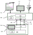
Fig. 1 shows a wireless communication system. The system includes a slave device 100 for wireless communication with a master device 120 (e.g., a mobile phone, laptop or tablet computer). The slave device is coupled to a plurality of peripherals 110, 111, 112 in order to provide services, e.g. rendering audio or video (AV) data. It should be noted that in this document, AV data is used for any type of video data, audio data, or combination of video data and audio data. The peripheral devices may include a video output device like a projector or a display 111, a graphical input/output device like a smart board 110 or a touch screen, an audio output device like a speaker system 112 or headphones, a user input device like a mouse or a room control unit; a data processing device like a data storage unit or a printer.
The slave device 100 has a slave device communication unit 102 for supplying wireless communication, such as a Wi-Fi unit as is well known. The slave device also has a slave device processor 101 arranged to couple to at least one master device. The process of docking a wireless device to a wireless docking slave device is a process of establishing a data link over an available radio channel (e.g. Wi-Fi or bluetooth) and is known as such, as discussed above with reference to WO 2012/117306a 1. For example, the description of bluetooth may be found in the bluetooth specification, core package version 2.1+ EDR, released on 26.7 months 2007. The docking process involves providing the master with access to one or more services, e.g. to one or more of the peripherals 110, 111, 112, as indicated by respective arrows 130, 131, 132.
The master 120 has a communication unit 121 for wireless communication and a master processor 122 coupled to the communication unit and arranged for said docking. In practice, there may be multiple communication units for this purpose, e.g., Bluetooth, Wi-Fi, and 60GHz (e.g., WiGig). The master processor 122 is arranged to interface as a master with a slave in order to be able to access at least one service.
One of the ways to make wireless connectivity simpler for users is wireless docking. In wireless docking, a so-called wireless docking slave device makes available to the mobile device a number of services with which the mobile device can set up a communication at one go. Any group of peripherals and/or services made available to a wireless docking slave device is referred to as a wireless docking environment. The wireless docking environment may include a single slave device and multiple peripheral devices, or the wireless docking slave device may offer multiple (different) wireless docking environments. The wireless docking slave may also make its services available through individual selection of each. There may also be multiple wireless docking slaves with which the mobile device is able to dock.
The master device 120 has a graphical user interface comprising a display 124, an interactive element for receiving user input and a graphical control unit 123 coupled to the display and the interactive element. The interactive element (not shown as such) is, for example, a touch screen sensitive to the touch of a user's fingertip on the screen or a mouse controlling a cursor on the screen. The graphics control unit may be a separate processor for generating display signals and receiving touch screen signals, or may be implemented as a function of the processor 122, such as by firmware. The graphical control unit is arranged to generate a system image comprising node elements, as further described with fig. 3. Each node element graphically represents a device or service, e.g., a master, a slave, or a provided service. The system image may also show connection elements between the node elements that graphically represent wireless connections between the devices represented by the connected node elements. Assume that a user wants to use a service, such as a display or print service. Thus, on the display screen, he draws a line from his device to the required service by using the touch screen as an interactive element. A line drawing input is received indicating a line drawn by the user in the system image between the selected node elements. The graphical control unit initiates a setup operation between selected devices corresponding to the selected node elements upon receiving a line drawing input. The operation may be transmitted to a processor or processor unit that controls the setting up of the wireless communication. The processor performs a setup operation by establishing a wireless connection between the selected devices.
Traditionally, the above-mentioned devices may employ Wi-Fi communication to make their wireless docking environment or functionality available wirelessly, e.g., by using Wi-Fi Direct. Setting up a Wi-Fi connection requires a number of steps to be taken and a large number of messages to be exchanged before two devices can associate' via Wi-Fi. This may require many users to participate in order to ensure that the correct device will be connected. When two devices associate through Wi-Fi, their Wi-Fi connection is password protected and an IP connection is established.
Wi-Fi devices may make themselves discoverable over the air. This may be done before the two devices associate, so this is called pre-association discovery. There are several types of pre-association discovery. One is pre-association device discovery whereby devices and certain properties of the devices, like their names, functions, etc. can be discovered. This may be accomplished by beacon frames and probe request frames and probe response frames as are well known from IEEE 802.11. Another type is pre-association service discovery, with which services such as printing, display, etc. offered by Wi-Fi devices can be discovered by other devices through IEEE 802.11u Generic Advertisement Service (GAS) frames. Such discovery may include information about the wireless docking environment provisioned for wireless docking.
Optionally, in the above wireless communication system, the wireless communication is according to a Wi-Fi standard for end-to-end communication, in particular as described in the Wi-Fi P2P standard. Advantageously, in practice, such Wi-Fi standard enables many existing devices to be incorporated in a wireless communication system by adding suitable applications that implement in particular the new functionality of the described graphical control unit. Typically, Wi-Fi protected settings are used to encrypt and authenticate Wi-Fi P2P connections. Based on the supported configuration methods for Wi-Fi protected setup of devices and services represented in the graphical UI, the master device may select the configuration method to use based on the following order of preference and representation in order to reduce the amount of user interaction beyond what is required for drawing lines in the graphical user interface:
1) the persistent P2P group is again initiated using the previously stored pairing certificate. Without any further user interaction.
2) The Wi-Fi Direct service default configuration method is used by using a fixed predetermined PIN. Without any further user interaction.
3) If connected to the wireless docking host, verifying whether the wireless docking host allows a wireless docking host assisted pairing method or channel Direct Link Setup (TDLS), thereby enabling certificate exchange for Wi-Fi devices managed by the wireless docking host and using these certificates for Direct connection Setup with these Wi-Fi devices without further user intervention.
4) If so, verifying whether the wireless docking host allows a relayed connection between the master device and the selected Wi-Fi device as a slave device through the wireless docking host, thereby enabling use of services for the selected Wi-Fi slave device without further user intervention.
5) The push-button pairing method is automatically initiated after drawing a line between the master device and the slave device. The user is informed through the graphical UI that the corresponding button is pressed to make a press-button pairing on the slave device.
6) If none of the above configuration methods are feasible, the method that requires the least amount of user intervention is selected. In practice, this may mean that going back to the PIN method "keypad" or "display" and the PIN needs to be entered in a text box (e.g. adjacent to the drawn line in the graphical user interface).
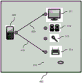
Fig. 2 shows an example of a wireless communication system with multiple slave devices. The figure shows three slave devices 251, 252, 253 connected to a set of peripheral devices (e.g., display 210, projection screen 211, personal audio 230 or public audio speaker 231, keyboard 240 and mouse 242). The connections between the various peripheral devices and the respective slave devices are unknown to the master device 220 or its user. Further peripherals may also be coupled via a peripheral interface like an ethernet connection for high speed access of peripherals or internet access used by the master, a USB interface or HDMI which can support multiple peripheral connections. The respective slave devices 251, 252, 253 may each provide one or more services, all of which are available to the master device 220. Each slave device has a communication unit 261, 262, 263 for wireless communication with the master device. This may be through a direct Wi-Fi connection or through bridging (bridging). The master device has a communication unit 223. The master device may select a service on the graphical user interface described with fig. 3 by drawing a line to the selected slave device. This allows the user to easily and intuitively select a peripheral device to be docked without having to carefully review several lists and go through the selection step. The user drawn lines also make the relationship between the device and the peripheral easy to understand. Links drawn in the graphical user interface may hide underlying connection details without a one-to-one correspondence between online and wireless links or sessions. For example, after drawing a line between the master device and the Wi-Fi peripheral connected/managed by the wireless docking host, whether a Wi-Fi P2P connection or a relay connection is set up between the master device and the Wi-Fi peripheral may be hidden from the user and may be decided by the wireless docking host or dockee based on the capabilities of the wireless docking host and/or dockee.
Optionally, the user is made aware of the above potential choices. In the case of a relay connection versus a direct connection, the user can draw different kinds of lines. For example, if the user draws a direct line, the direct connection is set up. If the user draws two lines of angled connection (e.g., like the caret '/\'), a relay connection is set up between the host device and the Wi-Fi peripheral.
Fig. 3 shows an example of a display of a graphical user interface showing a system image of a wireless communication system. Each element in the system is represented graphically by a node element, e.g., an icon and/or a connection symbol. A display 300 is shown while displaying a system image representing a wireless communication system having a master device 320 (e.g., represented by an icon showing a mobile phone and symbol 321) and a slave device 310 indicated by a dashed line and a connection symbol 330. A plurality of peripheral devices are coupled to the slave device, each peripheral device providing a respective service. Display peripheral 311 has connector symbols 331, audio output peripheral 312 has connector symbols 332, audio input peripheral 313 has connector symbols 333, and printer 314 has connector symbols 334. The symbol may also indicate the actual availability of the service, e.g. green indicating that the service is available and red indicating that the service is not currently available. The user may draw one or more lines between the master device and the selected service (i.e., between the corresponding connection symbols). Alternatively, different line types may be provided for wireless connection or session with the service, e.g. straight line for wireless connection, dashed or triangular line pattern for session. The user interface may provide a selection mechanism for the type of line to draw, or may detect and respond to an associated touch gesture. Further, audio and/or visual feedback may be generated when certain constraints are imposed on the drawn lines in the graphical user interface.
A graphical user interface in a wireless device is configured to generate a system image, such as a bitmap, with a graphical representation of the device and its connected peripherals. The graphical user interface is capable of drawing/sketching and erasing lines on the system image. Each such line represents a connection and/or session between a master device and a set of one or more peripherals/services provisioned for interfacing by the slave device(s). The slave device is also configured to set up (or tear down) a session between the master device and the selected peripheral/service, and if desired, the underlying wireless connection. A connection session may be represented in an image by: change the line or line connector point, or remove the line if such a session is not possible or broken or torn down.
The graphical control unit may therefore be arranged to receive, via the interactive element, a line wipe input indicating removal by a user of a connection element between selected node elements in the system image. Upon receiving the line erase input, the graphics control unit initiates a tear down operation that identifies the selected node element and the existing connection. The processor then performs a tear down operation by tearing down the respective existing connection(s) and/or session(s) between the selected node elements.
Optionally, the graphical control unit is arranged to receive, via the interactive element, a line direction input indicating an origin node at which a line drawn by the user in the system image starts and/or a destination node at which a line drawn by the user in the system image ends. The processor is arranged, upon receiving the line direction input, to perform a master function if the device corresponds to an origin node and/or a slave function if the device corresponds to a destination node. In practice, the wireless device may offer both wireless master and wireless slave functionality, and the device is further configured to determine the role of the wireless dockee/master for a session between the device and the set of peripheral devices offered for docking based on the starting point of the line drawn by the user on the system image. The direction of the lines may be indicated graphically by directional arrows. Furthermore, the graphics control unit may be arranged to receive, as the line direction input, a direction reversal input via the interaction element indicating a drawn line from a pre-existing destination node to a pre-existing origin node of the pre-existing connection. The processor is arranged to, upon receiving the line direction input, change the master function of the pre-existing origin node to the slave function if the device corresponds to the pre-existing origin node and/or change the slave function of the pre-existing destination node to the master function if the device corresponds to the pre-existing destination node. In practice, this makes it easy for the user to configure a master/slave relationship between the device using the peripheral device (i.e., the wireless dockee) and the device supplying the peripheral device (i.e., the wireless docking host), which does not need to be predetermined.
There may be some restrictions on supporting concurrent roles, for example, a Miracast sink cannot typically be a Miracast source at the same time.
The master role may indicate that a service explorer role to initiate discovery and P2P connection setup is performed, a USB host role is performed in case of media agnostic USB via Wi-Fi, a dockee role is performed in case of wireless docking with a wireless docking host, a Miracast source role in a Miracast session is performed in case of Wi-Fi Miracast, a P2P group owner role is performed or a P2P client role in a P2P group is performed, a primary user interface is run towards the user, etc. The slave role may indicate to perform a service advertiser role that allows discovery of its services, perform a USB hub or USB peripheral role in case of media agnostic USB via Wi-Fi, perform a dockee role in case of wireless docking with a wireless docking host, perform a Miracast sink role in a Miracast session in case of Wi-Fi Miracast, perform a P2P client role or perform a P2P group owner role in a P2P group, forward user interface actions to the master, and so on.
In order to generate a system image and enable the user interaction mechanisms described above, at least one wireless device in the system needs to gather information about: wireless connection capabilities/limitations, ongoing connections, support for different roles in the system, concurrency/resource limitations of other device(s) in the system. Preferably, this is done by collecting pre-association information that makes it available in 802.11 beacon frames or probe responses to probe requests or through 802.11u GAS frames. Typically, these frames are extended with function/service specific information elements or attributes that provide function/service specific information. For example, Wi-Fi P2P spec provides information such as friendly device name, device type, and whether a device can participate in more than one P2P group, and supported WPS configuration methods. For wireless docking, this may be extended with information such as: which peripherals are available for docking, how many simultaneous sessions can be supported, preferences of the device as a P2P group owner or P2P client, whether the device supports bridging to external Wi-Fi peripherals or facilitates direct connection setup. Alternatively or additionally, some of the information may be collected after associating and setting up an IP connection between the devices, e.g. by retrieving service/device specific information via UPnP.
Using the collected information, a system image may be generated to represent the devices/peripherals in the system, as illustrated in fig. 3 and 4. To do so, the device generating the system image may represent the device and peripheral with predefined icons, for example, by searching through a database of icons based on the device type provided via Wi-Fi P2P or USB device class, for example in the case of media agnostic USB via Wi-Fi. Alternatively, the icon is provided by other devices in the wireless network, for example using 802.11GAS frames or UPnP, or by providing a URL to enable retrieval of the icon from the internet via HTTP. The device generating the system image may display the system image to the user as part of its user interface. Alternatively, it may transmit the system image to another device in the network, for example using UPnP actions, which take the rendering of the system image as part of its user interface.
The apparatus that generates the user interface determines a set of anchor points in the system image that are associated with each device/peripheral represented in the system image. The anchor point may be a graphical icon or a corresponding connection symbol as shown in fig. 3 and 4. When a user begins drawing a line using a human interactive device (HID, such as a mouse, touch screen), the anchor point closest to the initial coordinates of the line determines the starting point of the line and can therefore be used to determine the role the device is to play in the corresponding service session (e.g., wireless dockee/master or wireless docking host/slave). The anchor point may also be used for "alignment", i.e. by automatically starting to draw lines from the anchor point, rather than the initial coordinates detected from the line drawing action performed by the HID device. The line may be drawn using free form drawing/delineation (e.g., following the coordinates of the HID device entirely) or by automatically drawing a straight line between the anchor point and the current coordinates of the HID device or another anchor point. The anchor point may not be visible but may also be rendered as part of or on top of the system image. In fig. 3 and 4, the anchor points are indicated by the symbols of the circular ring shape.
Fig. 4 shows an example of a display of a graphical user interface showing a system image of a wireless communication system with drawn connection lines. The figure shows the same system elements as in figure 3 on a display 400. A first line 410 representing a first connection element is drawn from the host device 320 (e.g., from its connection symbol) to the connection symbol of the printer 314. A second line 420 representing a second connection element draws a connection symbol from the master 320 to the display peripheral 311 indicating the selected display service.
A different color or some other visual or audio feedback may be used to indicate any connectivity constraints, for example, a red or light gray color indicating that the peripheral device is occupied/disconnected, or that the number of concurrent connections/sessions is exceeded, or that some other resource constraint is exceeded. A device providing a user interface may refuse to draw a line to an anchor point where it is not possible to establish a session to the device/peripheral/service represented by the anchor point (e.g., when the connection symbol has a red color). Based on the drawn line, the corresponding peripheral device is selected for use by the wireless dockee/master, e.g. by issuing a select peripheral device upnp (selective peripherals upnp) action with the identifier of the peripheral device as an argument. Corresponding service sessions may be set up to start using these peripheral devices over Wi-Fi via service specific messaging/streaming protocols, such as media agnostic USB or Wi-Fi Miracast over Wi-Fi.
To tear down a session, the device providing the user interface may offer an "eraser" function to delete the drawn line, or may detect a "cut" gesture by detecting a crossing line drawn at a particular angle relative to the drawn line.
Optionally, the wireless device may support multiple roles, e.g., wireless dockee and wireless docking host. The direction in which the line is drawn can be used to assign such a character. It may indicate that a device may only support one of a plurality of roles at a time. The device rendering the user interface may support drawing direct arrows to represent the relationship between the wireless dockee/master role and the wireless docking master/slave role. Additionally, the device may allow for dynamically changing the direction of the arrow, causing an MD/WDH role switch or a USB host/hub switch, for example using a message exchange to emulate a USB (USB-on-the-GO) role switch over GO. This may not only result in tearing down and re-establishing the session, but may also result in temporarily tearing down the underlying Wi-Fi P2P connection. This is because certain services for certain peripheral devices may require a particular role within the P2P group, such as the P2P group owner or the P2P client role. For example, the WDH may indicate, for example, the value "GO" or "Cli" as the role it wants/needs to play, for example, to run a USB channel on Wi-Fi services. The role of MD may not match the indicated role, e.g., when WDH indicates that it needs to become P2P GO but MD is currently the P2PGO for the P2P group between MD and WDH. Thus, before initiating a new session with the corresponding service, the MD would need to disconnect the current P2P connection with the WDH and initiate a new P2P connection between the MD and the WDH. This may involve issuing a offer discovery request with a set of connection capabilities to "Cli" (0x 02) or "GO" (0x03) that reverses the previous MD role, or setting the GO intent value to 15 by WDH.
Optionally, when generating the system image, other lines (e.g., additional colored bold lines) may be shown in addition to the lines drawn by the user to indicate a session to the peripheral device to indicate existing wireless connections or other relationships between devices. The device generating the system image may also be configured to collect wireless signal parameters from devices within wireless range that are capable of wireless docking in order to determine spatial locations between the devices and represent the spatial locations as part of the system image. This may make it easy for a user to understand the spatial relationship between multiple devices within range of the wireless docking capable and obtain enhanced understanding of the signal strength and when the devices are out of range.
Optionally, the mobile device may also notify the user that some or all of the required services are available. Such information about supported services may be made available through data structures provided via probe responses, GAS frame exchanges.
Such a signal may comprise several types of information, such as a docking service indication (see tables 1a, 1 b), or a master identifier (which may be a MAC address or any suitable identifier).
TABLE 1A-example of docking service indication
| Butt service indication (variable length string) | Evaluation of |
| Wi-Fi display | Providing video and audio reproduction via Wi-Fi |
| Wi-Fi direct service PRINT | Printing via Wi-Fi feed |
| WSB keyboard | WSB (Wireless Serial bus) is connected via Wi-FiUSB to supply |
| WSB mouse | |
| WSB display | |
| WSB Audio | |
| WSB video | USB video via Wi-Fi; alternative approaches for video. The WDH may offer more than one way to make a video screen available to the master device, and the master device may offer The method it supports is selected. |
| Internet connection | Supplying internet connectivity via WDH |
| WSB camera | |
| WSB microphone |
TABLE 1b example of digital docking service indications
| Docking service indication value (1) in third field An ASCII character) | Indicated docking service | Evaluation of |
| 0 | Wi-Fi display | Providing video and audio reproduction via Wi-Fi |
| 1 | Wi-Fi direct service PRINT | Printing via Wi-Fi feed |
| 2 | WSB keyboard | WSB (Wireless Serial bus) is USB supplied via Wi-Fi connection |
| 3 | WSB mouse | |
| 4 | WSB display | |
| 5 | WSB Audio | |
| 6 | WSB video | USB video via Wi-Fi; alternative approaches for video. WDH can be supplied in more than one kindIn such a way that a video screen is made available The master device can select the method supported by the master device. |
| 7 | Internet connection | Supplying internet connectivity via WDH |
| 8 | WSB camera | |
| 9 | WSB microphone |
The information provided may include a list of docking services and the status of each listed service together. The state may be available-not available, but may include more possibilities, such as "WDH supports services, but the service is being used by another master". The signals available for service include the following types of information
● Butt service indication (see tables 2a and 2 b)
● Master device identifier (e.g., MAC address or any suitable identifier)
The signal available for service may be a new signal in Wi-Fi ("frame" in Wi-Fi Direct terminology) or it may be embedded in an existing Wi-Fi frame, such as
●, the request is probed for,
● in response to the probe,
● the beacon frame of the beacon frame,
● GAS (general advertisement service) initial request frame
● GAS initial response frame
● GAS RESTORING REQUEST FRAME
● GAS recovery response frame
● GAS frames may also be used as protected GAS frames.
The probe request, probe response and beacon frame include attributes as previously explained. New attributes and their attribute values should be defined for the docking service indication and the master identifier. The docking service indication value may be, for example, using a string as shown in table 2a, or in table 2b, using a numerical value. Binary coding or hybrid coding is also possible.
TABLE 2 a-example of docking service indication

TABLE 2b example of digital docking service indication

Although the structure of the GAS frame is different from that for the probe request frame, the probe response frame, and the beacon frame, a signal available for service may be added to the GAS initial request frame, the GAS initial response frame, the GAS recovery request frame, the GAS recovery response frame, and their protected counterparts in a manner similar to that described above.
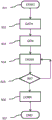
Fig. 5 illustrates a method for wireless communication using a service at a wireless device. The method enables wireless communication between a master device and one or more slave devices. The slave and master devices have already been explained with reference to fig. 1 and 2. The wireless device has a communication unit for wireless communication, a processor coupled with the communication unit and arranged for said interfacing, and a graphical user interface comprising a display and an interaction element for receiving user input. Initially, the method STARTs at START 501 and first information about devices and services in a wireless communication system is collected at gate 502. Subsequently, at GEN 503, a system image is generated to show node elements, each graphically representing one of a master, a slave, and at least one service, and connection elements between the node elements, each graphically representing a wireless connection. Next, at DRAW 504, line drawing input is received via the interactive element, indicating a line drawn by the user between selected node elements in the system image. Next, in INIT 505, upon receiving the completed line drawing input, a setup operation between selected devices corresponding to the selected node elements is initiated. Then, in the CONN 506, a setup operation is performed by establishing a wireless connection between the selected devices. Finally, at node END507, the method ENDs.
In practice, the method may be implemented in slave device software (slave device method) and master device software (master device method), for example in a so-called application (app). Such a computer program product is for wireless interfacing between a slave device and a master device and comprises a program operable to cause a processor to execute a slave device or master device method.
Although the invention has been mainly explained by embodiments using wireless docking, the invention is also suitable for any wireless system where a mobile device (having the role of master) wants to connect to another wireless device (having the role of slave) in order to connect, use or share one or more peripheral devices or services. It should be noted that the present invention can be implemented in hardware and/or software by using programmable components.
It will be appreciated that the above description for clarity has described embodiments of the invention with reference to different functional units and processors. However, it will be apparent that any suitable distribution of functionality between different functional units or processors may be used without detracting from the invention. For example, functionality illustrated to be performed by separate units, processors or controllers may be performed by the same processor or controller. Thus, references to specific functional units are only to be seen as references to suitable modules for providing the described functionality rather than implying a strict logical or physical structure or organization. The invention can be implemented in any suitable form including hardware, software, firmware or any combination of these.
It should be noted that in this document the word 'comprising' does not exclude the presence of other elements or steps than those listed and the word 'a' or 'an' preceding an element does not exclude the presence of a plurality of such elements, that any reference signs do not limit the scope of the claims, that the invention may be implemented by means of both hardware and software, and that several 'modules' or 'units' may be represented by the same item of hardware or software, possibly a processor may cooperate with hardware elements to fulfil the functions of one or more units. Furthermore, the invention is not limited to the embodiments described and lies in each and every novel feature or combination of features described above or recited in mutually different dependent claims.
Claims (18)
1. A wireless communication system comprising at least two wireless devices including a master device (120, 320) providing a master function and a slave device (100,310) providing a slave function, the slave device being arranged to provide at least one service, the master device being arranged to use the service, the slave device and the master device being arranged to provision the service via wireless communication, each of the at least two wireless devices comprising:
-a communication unit (102,121) for wireless communication,
-a processor (101, 122) coupled to the communication unit and arranged for the provisioning service,
a first device of the at least two wireless devices comprises a graphical user interface comprising a display (124), an interaction element for receiving user input, and a graphical control unit (123) coupled to the display and the interaction element,
characterized in that the graphics control unit is arranged to:
-generating a system image so as to show at least three node elements (310,311,312,313,314,320) and connection elements (410, 420) between the node elements, each node element graphically representing one of a master (320), a slave (310) or at least one service (311, 312,313, 314), and each connection element graphically representing a wireless connection or service session established between the node elements, the at least three node elements including a first node element (320) representing a first device;
-selecting a device to be connected by receiving a line drawing input via the interaction element indicating a line drawn by the user in the system image between two selected node elements of the at least three node elements; and
-upon receiving a line drawing input, initiating a setup operation for a wireless connection or service session between selected devices corresponding to the selected node elements, and
the processor is arranged to perform a setup operation by establishing a wireless connection or service session between the selected devices.
2. The wireless communication system as claimed in claim 1, wherein the at least one service comprises accessing and using at least one of:
-a peripheral device externally coupled to the slave device;
-an internal resource of the slave device;
-a network connected to the slave device.
3. A wireless communication system as claimed in claim 1, wherein a second device (100) of the at least two wireless devices comprises a display (111), and the graphical control unit in the first device is arranged to transmit the generated system image to the second wireless device, and
the second wireless device is arranged to receive the generated system image and to display the generated system image via the display.
4. A wireless device for use in a system as claimed in claim 1, the wireless device being the first device of the at least two wireless devices, the device comprising:
-a communication unit (121) for wireless communication,
-a processor (122) coupled to the communication unit and arranged for said provisioning service, and
-a graphical user interface comprising a display (124), an interactive element for receiving user input, and a graphical control unit (123) coupled to the display and the interactive element,
characterized in that the graphics control unit (123) is arranged to:
-generating a system image so as to show at least three node elements (310,311,312,313,314,320) and connection elements (410, 420) between the node elements, each node element graphically representing one of a master (320), a slave (310) or at least one service (311, 312,313, 314), and each connection element graphically representing a wireless connection or service session established between the node elements, the at least three node elements including a first node element (320) representing a first device;
-selecting a device to be connected by receiving a line drawing input via the interaction element indicating a line drawn by the user in the system image between two selected node elements of the at least three node elements; and
-upon receiving a line drawing input, initiating a setup operation for a wireless connection or service session between selected devices corresponding to the selected node elements, and
the processor is arranged to perform a setup operation by establishing a wireless connection or service session between the selected devices.
5. A wireless device as claimed in claim 4, wherein the graphics control unit (123) is arranged to:
-receiving via the interaction element a line wipe input indicating removal by a user of a connection element between selected node elements in the system image, and
-upon receiving a line erase input, initiating a tear down operation identifying the selected node element and an existing connection or service session, and
-the processor (122) is arranged to perform a tear down operation by tearing down an existing connection or service session between the selected node elements.
6. A wireless device as claimed in claim 4, wherein the graphics control unit (123) is arranged to select the master or slave function by receiving a line direction input via the interactive element, the line direction input indicating an origin node at which a line drawn by the user in the system image starts and/or a destination node at which a line drawn by the user in the system image ends, and
the processor (122) is arranged, upon receiving the line direction input, to perform a master function if the device corresponds to an original node and/or a slave function if the device corresponds to a destination node.
7. A wireless device as claimed in claim 6, wherein the graphics control unit (123) is arranged to select the master or slave function by receiving a direction reversal input as a line direction input via the interaction element, the direction reversal input indicating a drawn line from a pre-existing connected pre-existing destination node to a pre-existing origin node, and
the processor (122) is arranged, upon receiving the line direction input, to change a master function of the pre-existing origin node to a slave function if the device corresponds to the pre-existing origin node and/or to change a slave function of the pre-existing destination node to the master function if the device corresponds to the pre-existing destination node.
8. The wireless device as recited in claim 4,
the processor (122) is arranged to wirelessly receive information about its services, wireless connection capabilities and/or ongoing connections from another of the at least two wireless devices, and/or
The processor (101) is arranged to wirelessly transmit information about its services, wireless connection capabilities and/or ongoing connections to another device of the at least two wireless devices.
9. The wireless device as recited in claim 8, wherein the information is pre-associated information in the following frames: the beacon frame is either a probe response frame in response to the probe request or a GAS frame according to the Wi-Fi standard IEEE 802.11.
10. The wireless device as recited in claim 9, wherein the information in the frame is extended with a service-specific information element or attribute that provides service-specific information.
11. The wireless device as recited in claim 10, wherein the service-specific information indicates a graphical icon to be used in a corresponding node element in a system image.
12. The wireless device of claim 5, wherein,
the processor (122) is arranged to wirelessly receive information about its services, wireless connection capabilities and/or ongoing connections from another of the at least two wireless devices, and/or
The processor (101) is arranged to wirelessly transmit information about its services, wireless connection capabilities and/or ongoing connections to another device of the at least two wireless devices.
13. The wireless device of claim 6,
the processor (122) is arranged to wirelessly receive information about its services, wireless connection capabilities and/or ongoing connections from another of the at least two wireless devices, and/or
The processor (101) is arranged to wirelessly transmit information about its services, wireless connection capabilities and/or ongoing connections to another device of the at least two wireless devices.
14. The wireless device of claim 7,
the processor (122) is arranged to wirelessly receive information about its services, wireless connection capabilities and/or ongoing connections from another of the at least two wireless devices, and/or
The processor (101) is arranged to wirelessly transmit information about its services, wireless connection capabilities and/or ongoing connections to another device of the at least two wireless devices.
15. The wireless device of any of claims 4-14, wherein the graphical control unit (123) is arranged to access an icon database in order to retrieve icons to generate node elements corresponding to respective masters, slaves or services.
16. The wireless device according to any of claims 4-14, wherein the graphics control unit (123) is arranged to determine spatial distances between the wireless devices and to represent the relative spatial distances in the system image.
17. A method of initiating wireless communication for use in a wireless device in the system of claim 1, the wireless device being the first device of the at least two wireless devices and comprising:
-a communication unit (102) for wireless communication,
-a processor (101) coupled to the communication unit and arranged for said provisioning service, and
a graphical user interface comprising a display and an interactive element for receiving user input,
characterized in that the method comprises:
-generating a system image so as to show at least three node elements (310,311,312,313,314,320) and connection elements (410, 420) between the node elements, each node element graphically representing one of a master (320), a slave (310) or at least one service (311, 312,313, 314), and each connection element graphically representing a wireless connection or service session established between the node elements, the at least three node elements including a first node element (320) representing a first device;
-selecting a device to be connected by receiving a line drawing input via the interaction element indicating a line drawn by the user in the system image between two selected node elements of the at least three node elements; and
-upon receiving a line drawing input, initiating a setup operation for a wireless connection or service session between selected devices corresponding to the selected node elements, and
the processor is arranged to perform a setup operation by establishing a wireless connection or service session between the selected devices.
18. A computer-readable medium storing a computer program for initiating wireless communication for use in a wireless device in a system as claimed in claim 1, the wireless device being the first device of the at least two wireless devices, the computer program comprising a program operable to cause a processor to perform the method as claimed in claim 17.
Applications Claiming Priority (3)
| Application Number | Priority Date | Filing Date | Title |
|---|---|---|---|
| EP14166179 | 2014-04-28 | ||
| EP14166179.3 | 2014-04-28 | ||
| PCT/EP2015/057549 WO2015165697A1 (en) | 2014-04-28 | 2015-04-08 | Wireless communication system. |
Publications (2)
| Publication Number | Publication Date |
|---|---|
| CN106537848A CN106537848A (en) | 2017-03-22 |
| CN106537848B true CN106537848B (en) | 2020-08-11 |
Family
ID=50555085
Family Applications (1)
| Application Number | Title | Priority Date | Filing Date |
|---|---|---|---|
| CN201580023495.2A Active CN106537848B (en) | 2014-04-28 | 2015-04-08 | Wireless communication system |
Country Status (5)
| Country | Link |
|---|---|
| US (1) | US10200523B2 (en) |
| EP (2) | EP3138269B1 (en) |
| JP (1) | JP6469131B2 (en) |
| CN (1) | CN106537848B (en) |
| WO (1) | WO2015165697A1 (en) |
Families Citing this family (18)
| Publication number | Priority date | Publication date | Assignee | Title |
|---|---|---|---|---|
| KR102184488B1 (en) * | 2014-01-09 | 2020-11-30 | 삼성전자주식회사 | Mobile Device and Driving Method Thereof, and Image Display Apparatus and Driving Method Thereof |
| US20160231812A1 (en) * | 2015-02-06 | 2016-08-11 | The Eye Tribe Aps | Mobile gaze input system for pervasive interaction |
| US10921896B2 (en) | 2015-03-16 | 2021-02-16 | Facebook Technologies, Llc | Device interaction in augmented reality |
| US20170201558A1 (en) * | 2016-01-11 | 2017-07-13 | Hanwha Techwin Co., Ltd. | Method of managing a network and image obtaining apparatus |
| WO2017168512A1 (en) * | 2016-03-28 | 2017-10-05 | 株式会社ソシオネクスト | Communication device, communication method and communication program |
| US10601832B1 (en) * | 2016-03-30 | 2020-03-24 | Amazon Technologies, Inc. | Proxy captive portal traffic for input-limited devices |
| WO2017188704A2 (en) * | 2016-04-25 | 2017-11-02 | Samsung Electronics Co., Ltd. | Methods and systems for managing inter-device connectivity |
| CN106341810B (en) * | 2016-09-28 | 2019-05-17 | 维沃移动通信有限公司 | A kind of method and mobile terminal of double-card mobile terminal card selection |
| DE102017203685A1 (en) * | 2017-03-07 | 2018-09-13 | Robert Bosch Gmbh | Method for operating a system |
| US11070647B1 (en) * | 2017-03-14 | 2021-07-20 | Parallels International Gmbh | Seamless cross-platform synchronization of user activities and application data between mobile and desktop devices |
| KR102516019B1 (en) * | 2017-09-11 | 2023-03-30 | 삼성전자주식회사 | Electronic apparatus and method for communicating with an external electronic device |
| KR20190069247A (en) * | 2017-12-11 | 2019-06-19 | 삼성전자주식회사 | Electronic device for communication with external electronic device |
| US10212599B1 (en) * | 2018-02-19 | 2019-02-19 | Nxp B.V. | Method for preventing unauthorized use of electronic accessories |
| US10637746B2 (en) * | 2018-06-05 | 2020-04-28 | International Business Machines Corporation | Device-to-device connectivity control |
| US10993110B2 (en) * | 2018-07-13 | 2021-04-27 | Nvidia Corp. | Connectionless fast method for configuring Wi-Fi on displayless Wi-Fi IoT device |
| US10757561B2 (en) * | 2019-03-29 | 2020-08-25 | Intel Corporation | Wi-Fi docking in dense environment |
| US11341075B2 (en) * | 2020-08-12 | 2022-05-24 | Dell Products L.P. | Method for selectively connecting to a smart peripheral and system therefor |
| US20220311852A1 (en) * | 2021-03-25 | 2022-09-29 | Plantronics, Inc. | Desk phone / hotel station for mobile first workers |
Citations (3)
| Publication number | Priority date | Publication date | Assignee | Title |
|---|---|---|---|---|
| CN101739226A (en) * | 2009-12-21 | 2010-06-16 | 浙江工商大学 | Load balancing algorithm for drawing parallel graphic based on node migration |
| CN101982956A (en) * | 2010-08-19 | 2011-03-02 | 武汉理工大学 | Mobile network device and video and voice acquisition method thereof |
| CN103533667A (en) * | 2012-06-29 | 2014-01-22 | 索尼公司 | Communication control device, communication control method, program, and communication control system |
Family Cites Families (8)
| Publication number | Priority date | Publication date | Assignee | Title |
|---|---|---|---|---|
| US6326946B1 (en) * | 1998-09-17 | 2001-12-04 | Xerox Corporation | Operator icons for information collages |
| JP2003289313A (en) | 2002-03-28 | 2003-10-10 | Hewlett Packard Japan Ltd | Method for setting virtual local area network (vlan) |
| JP2004274532A (en) * | 2003-03-11 | 2004-09-30 | Toshiba Corp | Electronic apparatus and display method |
| JP2006120056A (en) * | 2004-10-25 | 2006-05-11 | Hewlett-Packard Development Co Lp | Database system and method thereof |
| US8244179B2 (en) * | 2005-05-12 | 2012-08-14 | Robin Dua | Wireless inter-device data processing configured through inter-device transmitted data |
| KR100758288B1 (en) * | 2006-02-10 | 2007-09-13 | 한국과학기술연구원 | Apparatus, system and method for inputting and outputting data based on hand operation |
| WO2012117306A1 (en) | 2011-03-01 | 2012-09-07 | Koninklijke Philips Electronics N.V. | Method for enabling a wireless secured communication among devices |
| US9226020B2 (en) | 2011-05-03 | 2015-12-29 | Lg Electronics Inc. | Electronic device and method for operating the same |
-
2015
- 2015-04-08 WO PCT/EP2015/057549 patent/WO2015165697A1/en active Application Filing
- 2015-04-08 US US15/306,846 patent/US10200523B2/en active Active
- 2015-04-08 JP JP2016559629A patent/JP6469131B2/en active Active
- 2015-04-08 CN CN201580023495.2A patent/CN106537848B/en active Active
- 2015-04-08 EP EP15713790.2A patent/EP3138269B1/en active Active
- 2015-04-08 EP EP15162709.8A patent/EP2940975A1/en not_active Withdrawn
Patent Citations (3)
| Publication number | Priority date | Publication date | Assignee | Title |
|---|---|---|---|---|
| CN101739226A (en) * | 2009-12-21 | 2010-06-16 | 浙江工商大学 | Load balancing algorithm for drawing parallel graphic based on node migration |
| CN101982956A (en) * | 2010-08-19 | 2011-03-02 | 武汉理工大学 | Mobile network device and video and voice acquisition method thereof |
| CN103533667A (en) * | 2012-06-29 | 2014-01-22 | 索尼公司 | Communication control device, communication control method, program, and communication control system |
Also Published As
| Publication number | Publication date |
|---|---|
| WO2015165697A1 (en) | 2015-11-05 |
| JP6469131B2 (en) | 2019-02-13 |
| CN106537848A (en) | 2017-03-22 |
| US20170048373A1 (en) | 2017-02-16 |
| EP3138269B1 (en) | 2019-08-07 |
| EP2940975A1 (en) | 2015-11-04 |
| JP2017518657A (en) | 2017-07-06 |
| US10200523B2 (en) | 2019-02-05 |
| EP3138269A1 (en) | 2017-03-08 |
Similar Documents
| Publication | Publication Date | Title |
|---|---|---|
| CN106537848B (en) | Wireless communication system | |
| JP6246796B2 (en) | System and method for wireless docking using a wireless docking profile | |
| TWI489295B (en) | Automatic configuration of electronic devices | |
| US20150256957A1 (en) | User terminal device, audio system, and method for controlling speaker thereof | |
| JP6145228B1 (en) | Wireless communication system | |
| EP3312730A1 (en) | Control terminal device, audio system, and audio system control method | |
| US20160209997A1 (en) | Apparatus and method for displaying connection status in network | |
| CN105814512B (en) | Wireless docking system | |
| KR101297152B1 (en) | Mapping server and mapping method | |
| US20150019978A1 (en) | Information processing apparatus, information processing method, and program | |
| JP7018110B1 (en) | Mobile device dock | |
| EP3267737B1 (en) | Wireless communication system and wireless communication device | |
| JP6310624B1 (en) | Computer system, setting method and program | |
| CN115883897A (en) | Display device, startup navigation configuration method and storage medium |
Legal Events
| Date | Code | Title | Description |
|---|---|---|---|
| C06 | Publication | ||
| PB01 | Publication | ||
| SE01 | Entry into force of request for substantive examination | ||
| SE01 | Entry into force of request for substantive examination | ||
| GR01 | Patent grant | ||
| GR01 | Patent grant |