CN106465399B - Full duplex operation method and system in wireless communication network - Google Patents
Full duplex operation method and system in wireless communication network Download PDFInfo
- Publication number
- CN106465399B CN106465399B CN201580034068.4A CN201580034068A CN106465399B CN 106465399 B CN106465399 B CN 106465399B CN 201580034068 A CN201580034068 A CN 201580034068A CN 106465399 B CN106465399 B CN 106465399B
- Authority
- CN
- China
- Prior art keywords
- interference
- network node
- path loss
- processor
- interfering
- Prior art date
- Legal status (The legal status is an assumption and is not a legal conclusion. Google has not performed a legal analysis and makes no representation as to the accuracy of the status listed.)
- Active
Links
Images


Classifications
-
- H—ELECTRICITY
- H04—ELECTRIC COMMUNICATION TECHNIQUE
- H04W—WIRELESS COMMUNICATION NETWORKS
- H04W72/00—Local resource management
- H04W72/20—Control channels or signalling for resource management
- H04W72/23—Control channels or signalling for resource management in the downlink direction of a wireless link, i.e. towards a terminal
-
- H—ELECTRICITY
- H04—ELECTRIC COMMUNICATION TECHNIQUE
- H04W—WIRELESS COMMUNICATION NETWORKS
- H04W72/00—Local resource management
- H04W72/50—Allocation or scheduling criteria for wireless resources
- H04W72/54—Allocation or scheduling criteria for wireless resources based on quality criteria
- H04W72/541—Allocation or scheduling criteria for wireless resources based on quality criteria using the level of interference
-
- H—ELECTRICITY
- H04—ELECTRIC COMMUNICATION TECHNIQUE
- H04L—TRANSMISSION OF DIGITAL INFORMATION, e.g. TELEGRAPHIC COMMUNICATION
- H04L5/00—Arrangements affording multiple use of the transmission path
- H04L5/0001—Arrangements for dividing the transmission path
- H04L5/0003—Two-dimensional division
- H04L5/0005—Time-frequency
-
- H—ELECTRICITY
- H04—ELECTRIC COMMUNICATION TECHNIQUE
- H04L—TRANSMISSION OF DIGITAL INFORMATION, e.g. TELEGRAPHIC COMMUNICATION
- H04L5/00—Arrangements affording multiple use of the transmission path
- H04L5/0091—Signaling for the administration of the divided path
- H04L5/0096—Indication of changes in allocation
-
- H—ELECTRICITY
- H04—ELECTRIC COMMUNICATION TECHNIQUE
- H04L—TRANSMISSION OF DIGITAL INFORMATION, e.g. TELEGRAPHIC COMMUNICATION
- H04L5/00—Arrangements affording multiple use of the transmission path
- H04L5/14—Two-way operation using the same type of signal, i.e. duplex
-
- H—ELECTRICITY
- H04—ELECTRIC COMMUNICATION TECHNIQUE
- H04L—TRANSMISSION OF DIGITAL INFORMATION, e.g. TELEGRAPHIC COMMUNICATION
- H04L5/00—Arrangements affording multiple use of the transmission path
- H04L5/14—Two-way operation using the same type of signal, i.e. duplex
- H04L5/16—Half-duplex systems; Simplex/duplex switching; Transmission of break signals non-automatically inverting the direction of transmission
-
- H—ELECTRICITY
- H04—ELECTRIC COMMUNICATION TECHNIQUE
- H04W—WIRELESS COMMUNICATION NETWORKS
- H04W24/00—Supervisory, monitoring or testing arrangements
- H04W24/08—Testing, supervising or monitoring using real traffic
-
- H—ELECTRICITY
- H04—ELECTRIC COMMUNICATION TECHNIQUE
- H04W—WIRELESS COMMUNICATION NETWORKS
- H04W52/00—Power management, e.g. TPC [Transmission Power Control], power saving or power classes
- H04W52/04—TPC
- H04W52/18—TPC being performed according to specific parameters
- H04W52/24—TPC being performed according to specific parameters using SIR [Signal to Interference Ratio] or other wireless path parameters
- H04W52/243—TPC being performed according to specific parameters using SIR [Signal to Interference Ratio] or other wireless path parameters taking into account interferences
-
- H—ELECTRICITY
- H04—ELECTRIC COMMUNICATION TECHNIQUE
- H04W—WIRELESS COMMUNICATION NETWORKS
- H04W72/00—Local resource management
- H04W72/12—Wireless traffic scheduling
- H04W72/121—Wireless traffic scheduling for groups of terminals or users
Abstract
Methods, apparatuses, and computer software for communicating in a wireless communication network including a scheduling entity configured to enable full duplex communication and a User Equipment (UE) configured to enable half duplex communication are disclosed. In some examples, one or more UEs may be configured to enable limited (quasi-) full duplex communication. Some aspects relate to scheduling a UE, comprising: it is determined whether it is appropriate to co-schedule the UEs to share time-frequency resources based on one or more factors, such as path loss between devices.
Description
Cross Reference to Related Applications
This application claims priority to provisional patent application No.62/017,182 filed on U.S. patent and trademark office at 6/25 2014 and non-provisional patent application No.14/535,745 filed on U.S. patent and trademark office at 11/7 2014, and both applications are hereby incorporated by reference in their entirety for all purposes as if fully set forth herein.
Technical Field
Aspects of the present disclosure relate generally to wireless communication systems, and more particularly, to scheduling algorithms for wireless communication systems that combine full-duplex and half-duplex nodes.
Background
Wireless communication networks have been widely deployed to provide various communication services such as telephony, video, data, messaging, broadcast, and so on. These networks are typically multiple-access networks that support communication for multiple users by sharing the available network resources. In many networks, resources are allocated for bidirectional communications using Time Division Duplexing (TDD) or Frequency Division Duplexing (FDD). In TDD or FDD, communication using a single frequency channel is only possible in one direction at any given time. Thus, TDD and FDD networks implement full duplex functionality by using multiple frequency channels (as in the case of FDD), or by dividing the two directions of communication according to allocated time slots (as in the case of TDD).
Recently, as the technology of interference cancellation techniques has improved, true radio level full duplex communication is possible, where in this case, at the same time, two-way communication occurs between devices using a single frequency channel. As the demand for mobile broadband access continues to increase, research and development continue to advance wireless communication technologies not only to meet the growing demand for mobile broadband access, but also to enhance and enhance the user experience.
Disclosure of Invention
The following presents a simplified summary of one or more aspects of the disclosure in order to provide a basic understanding of such aspects. This summary is not an extensive overview of all contemplated features of the disclosure, and is intended to neither identify key or critical elements of all aspects of the disclosure, nor delineate the scope of any or all aspects of the disclosure. Its sole purpose is to present some concepts of one or more aspects of the disclosure in a simplified form as a prelude to the more detailed description that is presented later.
Some aspects of the present disclosure provide methods, apparatus, and computer software for communicating in a wireless communication network, wherein the wireless communication network includes a scheduling entity configured for full duplex communication and a User Equipment (UE) configured for half duplex communication. In some examples, one or more UEs may be configured for restricted (quasi-) full duplex communication. Some aspects relate to scheduling a UE, comprising: it is determined whether it is appropriate to co-schedule the UEs to share time-frequency resources based on one or more factors, such as path loss between devices.
In one aspect, the present disclosure provides a network node configured for wireless communication, comprising at least one processor, a computer-readable medium communicatively coupled to the at least one processor, and a transceiver communicatively coupled to the at least one processor. Here, the at least one processor may be configured to: using a transceiver to communicate with a first device and a second device by using half-duplex communication with each of the first device and the second device; determining an inter-device path loss between a first device and a second device; and if the path loss between the first equipment and the second equipment is larger than the threshold, the first equipment and the second equipment are cooperatively scheduled to use the first time-frequency resource.
Another aspect of the disclosure provides a method of wireless communication operable at a network node. Here, the method includes: communicating with the first device and the second device by using half-duplex communication with each of the first device and the second device; determining an inter-device path loss between a first device and a second device; and if the path loss between the first equipment and the second equipment is larger than the threshold, the first equipment and the second equipment are cooperatively scheduled to use the first time-frequency resource.
Another aspect of the disclosure provides a UE configured for wireless communication, comprising at least one processor, a computer-readable medium communicatively coupled to the at least one processor, and a transceiver communicatively coupled to the at least one processor. Here, the at least one processor may be configured to: using a transceiver to communicate with a network node using half-duplex communication; using a transceiver to receive an interference discovery signal from an interfering UE; using a transceiver to transmit an interference report to a network node corresponding to a strength of the received interference discovery signal; and using the transceiver to receive a resource allocation from the network node, wherein the resource allocation is scheduled in coordination with the interfering UE only if a path loss corresponding to the strength of the received interfering discovery signal is greater than a threshold.
Another aspect of the disclosure provides a method of wireless communication operable at a UE. Here, the method includes: communicating with a network node using half-duplex communication; receiving an interference discovery signal from an interfering UE; transmitting an interference report corresponding to the strength of the received interference discovery signal to a network node; receiving a resource allocation from a network node, wherein the resource allocation is scheduled in cooperation with the interfering UE only if a pathloss corresponding to a strength of the received interfering discovery signal is greater than a threshold.
These and other aspects of the invention will be more fully understood after reading the following detailed description. Other aspects, features and embodiments of the present invention will become apparent to those ordinarily skilled in the art upon review of the following description of specific, exemplary embodiments of the invention in conjunction with the accompanying figures. While features of the invention are discussed with respect to certain embodiments and figures below, all embodiments of the invention can include one or more of the advantageous features discussed herein. In other words, while one or more embodiments may be discussed as having certain advantageous features, one or more of these features may also be used in accordance with the various embodiments of the invention discussed herein. In a similar manner, although exemplary embodiments are discussed below as being device, system, or method embodiments, it should be understood that these exemplary embodiments can be implemented with a wide variety of devices, systems, and methods.
Drawings
Fig. 1 is a block diagram illustrating an example of a hardware implementation for using a scheduling entity of a processing system, according to some embodiments.
Fig. 2 is a block diagram illustrating an example of a hardware implementation for a User Equipment (UE) using a processing system, in accordance with some embodiments.
Fig. 3 is a block diagram illustrating an example of a wireless communication network including a full-duplex scheduling entity and a half-duplex UE, in accordance with some embodiments.
Fig. 4 is a flow diagram illustrating a process for determining whether to co-schedule a pair of UEs in time-frequency resources, in accordance with some embodiments.
Fig. 5 is a block diagram illustrating an example of a wireless communication network with interference discovery and interference reporting signaling, including a full-duplex scheduling entity and a half-duplex UE, in accordance with some embodiments.
Fig. 6 is a flow diagram illustrating a process for interference discovery and co-scheduling UEs, according to some embodiments.
Fig. 7 is a flow diagram illustrating another process for interference discovery and co-scheduling UEs, in accordance with some embodiments.
Fig. 8 is a flow diagram illustrating a process for determining inter-UE path loss and co-scheduling UEs using inter-UE distance, in accordance with some embodiments.
Fig. 9 is a schematic diagram illustrating the use of radial coordinates to determine inter-UE distance, in accordance with some embodiments.
Fig. 10 is a block diagram illustrating an example of a wireless communication network including a full-duplex base station and a half-duplex UE with additional details of signal parameters, in accordance with some embodiments.
Fig. 11 is a flow diagram illustrating a process for determining whether to implement quasi-full duplex communication at a scheduling entity based on feasibility conditions, according to some embodiments.
Fig. 12 is a block diagram illustrating an example of a wireless communication network including a full-duplex base station and a restricted full-duplex UE, in accordance with some embodiments.
Fig. 13 is a flow diagram illustrating a process of controlling a quasi-full-duplex UE, according to some embodiments.
Fig. 14 is a block diagram illustrating an example of a wireless communication network including a full-duplex base station and a limited full-duplex UE with additional details of generalized signal parameters, in accordance with some embodiments.
Fig. 15 is a block diagram illustrating an example of a wireless communication network including a full-duplex base station and a half-duplex UE with additional details of generalized signal parameters, according to some embodiments.
Fig. 16 is a block diagram illustrating an example of a wireless communication network including intermediate relay nodes operating in full duplex mode between a plurality of anchor base stations and a plurality of terminal UEs, in accordance with some embodiments.
Fig. 17 is a block diagram illustrating an example of a wireless communication network including a relay node that receives downlink data from an anchor base station and transmits downlink data to a UE, in accordance with some embodiments.
Fig. 18 is a block diagram illustrating an example of a wireless communication network including a relay node that receives uplink data from a UE and transmits uplink data to an anchor base station, in accordance with some embodiments.
Fig. 19 is a block diagram illustrating an example of a wireless communication network including a relay node that transmits downlink data to a first UE and receives uplink data from a second UE, in accordance with some embodiments.
Fig. 20 is a block diagram illustrating an example of a wireless communication network including a relay node that receives downlink data from a first base station and transmits uplink data to a second base station, in accordance with some embodiments.
Fig. 21 is a block diagram illustrating an example of a wireless communication network including relay nodes to transmit data to and receive data from a full-duplex base station, in accordance with some embodiments.
Fig. 22 is a block diagram illustrating an example of a wireless communication network including relay nodes to transmit data to and receive data from full-duplex UEs, in accordance with some embodiments.
Detailed Description
The detailed description set forth below in connection with the appended drawings is intended as a description of various configurations and is not intended to represent the only configurations in which the concepts described herein may be practiced. The detailed description includes specific details for the purpose of providing a thorough understanding of various concepts. It will be apparent, however, to one skilled in the art that these concepts may be practiced without these specific details. In some instances, well-known structures and components are shown in block diagram form in order to avoid obscuring such concepts.
Fig. 1 is a conceptual diagram illustrating an example of a hardware implementation for an apparatus 100 using a processing system 114. In accordance with various aspects of the disclosure, an element or any portion of an element or any combination of elements may be implemented using processing circuitry 114 including one or more processors 104. For example, the apparatus 100 may be a scheduling entity, a network node, a Base Station (BS), or a relay station, as illustrated in any of fig. 3, 5, 9, 10, 12, 14, 15, 16, 17,18, 19, 20, 21, and/or fig. 22. Examples of processor 104 include microprocessors, microcontrollers, Digital Signal Processors (DSPs), Field Programmable Gate Arrays (FPGAs), Programmable Logic Devices (PLDs), state machines, gated logic, discrete hardware circuits, and other suitable hardware configured to perform the various functions described throughout this disclosure. That is, the processor 104, as used in the apparatus 100, may be used to implement any one or more of the processes described below.
In this example, the processing system 114 may be implemented with a bus architecture, represented generally by the bus 102. The bus 102 may include any number of interconnecting buses and bridges depending on the specific application of the processing system 114 and the overall design constraints. The bus 102 links together various circuits including one or more processors, represented generally by the processor 104, a memory 105, and a computer-readable medium, represented generally by the computer-readable medium 106. The bus 102 may also link various other circuits such as clock sources, peripherals, voltage regulators, and power management circuits, which are well known in the art, and therefore, are not described in any further detail. Bus interface 108 provides an interface between bus 102 and transceiver 110. The transceiver 110 provides a means for communicating with various other apparatus over a transmission medium. In various examples, transceiver 110 may include one or more antennas, and in a multiple antenna example, transceiver 110 may be enabled to determine an angle at which a received signal arrives. The transceiver 110 may include various subcomponents configured to implement wireless communication, including, but not limited to, one or more power amplifiers, transmitters, receivers, filters, oscillators, and the like. Depending on the nature of the device, a user interface 112 (e.g., keypad, display, speaker, microphone, joystick) may also be provided.
The processor 104 is responsible for managing the bus 102 and general processing, including the execution of software stored on the computer-readable medium 106. The software, when executed by the processor 104, causes the processing system 114 to perform the various functions described infra for any particular apparatus. The computer-readable medium 106 may also be used for storing data that is manipulated by the processor 104 when executing software.
One or more processors 104 in the processing system may execute software. Whether software is referred to as software, firmware, middleware, microcode, hardware description language, or another terminology, it should be broadly interpreted to mean instructions, instruction sets, code segments, program code, programs, subroutines, software modules, applications, software packages, routines, subroutines, objects, executables, threads of execution, procedures, functions, and the like. The software may reside in computer readable medium 106. Computer-readable media 106 may be non-transitory computer-readable media. By way of example, non-transitory computer-readable media include magnetic storage devices (e.g., hard disk, floppy disk, magnetic strips), optical disks (e.g., Compact Disk (CD) or Digital Versatile Disk (DVD)), smart cards, flash memory devices (e.g., card, stick, or key drive), Random Access Memory (RAM), Read Only Memory (ROM), programmable ROM (prom), erasable prom (eprom), electrically erasable prom (eeprom), registers, a removable disk, and any other suitable medium for storing software and/or instructions that can be accessed and read by a computer. By way of example, computer-readable media may also include carrier wave forms, transmission lines, and any other suitable media for transmitting software and/or instructions that can be accessed and read by a computer. The computer-readable medium 106 may be located in the processing system 114, external to the processing system 114, or distributed among multiple entities including the processing circuit 114. The computer-readable medium 106 may be embodied as a computer program product. By way of example, a computer program product may include a computer-readable medium in a packaging material. Those of ordinary skill in the art will recognize how best to implement the described functionality presented throughout this disclosure, depending on the particular application and design constraints imposed on the overall system.
In some aspects of the disclosure, the processor 104 may include half-duplex communication circuitry 141, which may function in coordination with half-duplex communication software 161. Here, half-duplex communication circuitry 141 and/or software 161 may use transceiver 110 to enable communication with one or more devices (e.g., UE200 described further below) using half-duplex communication techniques (e.g., Time Division Duplex (TDD) and/or Frequency Division Duplex (FDD)).
The processor 104 may also include full duplex communication circuitry 142, which may function in coordination with full duplex communication software 162. Here, the full-duplex communication circuitry 141 and/or software 161 may utilize a single frequency channel to enable full-duplex communication with one or more devices (e.g., UE 200). In some examples, the full-duplex communication circuit 141 may function in coordination with the interference cancellation circuit 143.
That is, the processor 104 may also include an interference cancellation circuit 143, which may function in coordination with the interference cancellation software 163. Here, the interference cancellation circuitry 143 and/or software 163 may be configured to implement automatic interference cancellation at the transceiver 110, which may be used to cancel intra-device interference (e.g., self-interference). The interference cancellation circuitry 143 and/or software 163 may use any suitable interference cancellation algorithm or technique, including but not limited to: antenna/RF isolation, transmit signal reconstruction and cancellation (e.g., using digital baseband signals and/or transceiver output signals, channel response estimation, transceiver non-linearity modeling, etc.), power amplifier noise cancellation, and so forth. In some examples, the interference cancellation circuitry 143 and/or software 163 may also be used to cancel inter-device interference. That is, interference with one or more other transmitting devices. The interference cancellation circuitry 143 and/or software 163 may include any suitable filter or equalizer configured to perform interference cancellation.
The processor 104 may also include resource allocation and scheduling circuitry 145, which may function in coordination with resource allocation and scheduling software 165. Here, the resource allocation and scheduling circuitry 145 and/or software 165 may allocate resources to one or more devices (e.g., UE200) for communicating with the network node/scheduling entity 100 and/or resources for communication between UEs (e.g., for interfering discovery signals); it may use any suitable resource selection scheme to select resources for allocation, including but not limited to: a random selection or a selection corresponding to an identifier unique to the respective device; it may schedule time-frequency resources for use by one or more devices (e.g., UE 200); it may determine whether to co-schedule two or more devices (e.g., UE200) to use the same time-frequency resources based on one or more factors or parameters (e.g., whether their inter-device path loss is greater than a path loss threshold 151), based on the path loss between the respective device and the network node/scheduling entity 100, and/or based on the data rate and/or data type 153 used by the respective device. Further, the resource allocation and scheduling circuitry 145 and/or software 165 may function in coordination with the transceiver 110 to transmit a resource allocation signal to a device (e.g., UE 200).
The processor 104 may also include optional backhaul communication circuitry 146, which may function in coordination with optional backhaul communication software 166. Here, the backhaul communication circuit 146 and/or software 166 may enable communication with upstream nodes using any suitable wired or wireless backhaul communication interface. The backhaul communication circuitry 146 and/or software 166 are optional and may generally be included in examples where the network node/scheduling entity 100 is a relay node, which examples will be described in further detail below.
Fig. 2 is a block diagram illustrating an example of a hardware implementation for an apparatus 200 using a processing system 214. According to various aspects of the disclosure, an element or any portion of an element or any combination of elements may be implemented with a processing system 214 that includes one or more processors 204. For example, the apparatus 200 may be a User Equipment (UE), as shown in any of fig. 3, 5, 9, 10, 12, 14, 15, 16, 17,18, 19, 20, 21, and/or fig. 22. The device 200 has many components that are the same as or similar to those described above in connection with fig. 1. For example, the bus 202, bus interface 208, transceiver 210, and user interface 212 are substantially the same as those described above in connection with FIG. 1. Further, the processor 204, memory 205, and computer-readable medium 206 have many similarities to those so-named components described above in connection with fig. 1, except for the differences described herein below.
That is, in various aspects of the disclosure, the processor 204 may include half-duplex communication circuitry 241, which may function in coordination with half-duplex communication software 261. Here, half-duplex communication circuitry 241 and/or software 261 may use transceiver 210 to enable communication with one or more devices using half-duplex communication techniques, such as Time Division Duplex (TDD) and/or Frequency Division Duplex (FDD).
The processor 204 may also include full-duplex communication circuitry 242, which may function in coordination with full-duplex communication software 262. Here, the full-duplex communication circuitry 242 and/or software 262 may function in coordination with interference cancellation circuitry 243 and/or software 262 (described below) to enable full-duplex communication with one or more devices using a single frequency channel. Thus, for example, the full-duplex communication circuitry 242 and/or software 262 may enable full-duplex communication if the configured transmit power is below the transmit power threshold 253. In some examples, the full-duplex communications circuitry 242 and/or software 262 may be optional, and some UEs may lack such full-duplex communications capability.
The processor 204 may also include interference cancellation circuitry 243, which may function in coordination with interference cancellation software 263. Here, the interference cancellation circuit 243 and/or software 263 may implement interference cancellation (e.g., automatic interference cancellation), e.g., for cancelling intra-device interference (e.g., self-interference) and/or for cancelling inter-device interference. Further, the interference cancellation circuit 243 and/or software 263 may include any suitable filter or equalizer configured to perform interference cancellation.
The processor 204 may also include interference determination and report generation circuitry 244, which may function in coordination with interference determination and report generation software 264. Here, the interference determination and report generation circuitry 244 and/or software 264 may enable determination of an interference level corresponding to an interfering device (e.g., by determining a strength of an interference discovery signal received from the interfering device), and accordingly generate an interference report based on the determined interference level and transmit the interference report to the network node/scheduling entity 100 (e.g., with the transceiver 210). Further, the interference determination and report generation circuitry 244 and/or software 264 may calculate and store a path loss value 251, which may be included in the transmitted report.
Introduction to the design reside in
In a wireless communication system, a communication device may exhibit full-duplex or half-duplex functionality. In the case of half-duplex operation, communication is possible on a particular channel only in one direction at a time, which is typically time-divided between segments in one direction or the other. This situation is commonly referred to as Time Division Duplexing (TDD). In the case of full duplex operation simultaneous communication to and from one device is possible.
In currently deployed systems, full duplex functionality is typically achieved by using Frequency Division Duplexing (FDD), where one frequency band is used for communication in one direction and another frequency band is used for communication in another direction. In these deployments, although the communication is full duplex in time, it is still half duplex in the frequency domain, since on each channel, communication can still only be made in one direction.
A communication node that truly implements full duplex at the radio level simultaneously uses the same frequency channel to transmit and receive signals. In the following description, the term full duplex is used to refer to radio level full duplex operation on the same frequency channel at the same time. Furthermore, in the following disclosure, time division duplex and frequency division duplex (TDD and FDD) systems are both considered as radio level half duplex systems.
Recently, due in part to improvements in active interference cancellation techniques, radio level full duplex functionality (where full duplex communication can be achieved using a single frequency channel) with high reliability is possible. In this system, it may be the case that some wireless nodes (e.g., base stations, enodebs, access points, scheduling entities, etc.) may be configured with full-duplex radios for true radio-level full-duplex functionality, while some other nodes (e.g., wireless devices, UEs, subordinate entities, etc.) may be configured with only half-duplex radios for radio-level half-duplex functionality. Furthermore, some radios in the system may have partial and/or conditional full-duplex capability, e.g., they only use half-duplex functionality unless certain conditions are met.
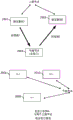
Fig. 3 is a simplified block diagram illustrating an exemplary wireless communication network having a full-duplex capable base station 302 in communication with two UEs 304 and 306 capable of only half-duplex communication. In the diagram, the base station 302 is shown transmitting downlink signals to a first UE 304 while receiving uplink signals from a second UE 306.
In such networks, interference between half-duplex nodes can be a problem in the case where full-duplex nodes communicate with half-duplex nodes. For example, as illustrated by the scenario in fig. 3, the first UE 304 and the second UE 306 are co-scheduled such that the first UE 304 is allocated to use a particular resource for receiving downlink signals, while the second UE 306 is allocated to use the same particular resource for transmitting uplink signals. In this case, co-scheduling the two UEs may cause transmissions from the second UE 306 to generate cross-device interference, which affects the reception performance of the first UE 304. In the wireless communication system, when the base station 302 or other scheduling node is operating in full duplex mode, a scheduling entity 308 (e.g., a medium access control or MAC layer scheduler) or any other suitable scheduling node at the base station 302 benefits by taking appropriate precautions to mitigate such UE cross-interference. Such device cross-interference may be reduced, for example, when the path loss between UEs is large. Accordingly, various aspects of the present disclosure explore methods according to which a base station may select UEs to be co-scheduled, e.g., based on path loss between respective UEs. Additional aspects of the disclosure consider the data rates allocated to the transmitter and receiver links at the base station when co-scheduling these UEs.
Thus, in one or more aspects of the disclosure, a wireless communication network may be configured to select a pair of UEs with sufficiently large inter-UE path loss such that a scheduling node or base station may transmit to one UE and receive from another UE using the same time-frequency resources while reducing or avoiding device cross-interference between the respective UEs. In various aspects of the disclosure, some methods or algorithms for determining inter-UE path loss are presented. The base station or scheduling node may also select UEs such that their path loss to the base station is small enough to maintain the required link SINR, and/or may determine the data rate or type of data (traffic and control) used by each of the two links so that both links in a full duplex configuration meet the SINR target.
Fig. 4 is a flow diagram illustrating an example process 400 for determining whether to co-schedule a given pair of UEs in accordance with one or more aspects of the present disclosure. In some examples, process 400 may be performed by a network node (e.g., scheduling entity 100 and/or processing system 114 as described above and shown in fig. 1). In some examples, process 400 may be performed by any suitable means for implementing the described functionality.
At block 402, the scheduling entity 100 may communicate with a first device (e.g., UE200) and a second device (e.g., UE200) by using half-duplex communication with each of the first device and the second device. Here, the scheduling entity 100 may determine the inter-device path loss between the first device and the second device using any suitable inter-device path loss discovery algorithm, method, or technique. Some such inter-device path loss algorithms will be described below. If the discovered inter-UE path loss is high (e.g., greater than some suitable path loss threshold), the process may proceed to block 404. Here, the scheduling entity 100 may cooperatively schedule the first device and the second device to use the same time-frequency resource. On the other hand, if the discovered inter-UE path loss is low (e.g., not greater than the path loss threshold), the process may proceed to block 406. Here, the scheduling entity 100 does not schedule the first device and the second device to use the same time-frequency resource in cooperation.
Discovery of path loss between UEs
In accordance with one or more aspects of the present disclosure, a network node, base station, or other scheduling entity (hereinafter scheduling entity) may be implemented to discover inter-UE path loss. Here, the path loss may be an attenuation amount of a signal from transmission to reception. That is, due to one or more factors or conditions, the power or energy of a signal may be less when it is received at a receiving device than when it is transmitted from a transmitting device. This change is commonly referred to as path loss. In various embodiments, inter-UE or inter-device path loss may be discovered using any one or more of a variety of techniques, methods, or algorithms. By taking into account this path loss, two or more co-scheduled UEs (e.g., at least one UE scheduled to transmit and at least one other UE scheduled to receive using the same time-frequency resources) may cause a suitably low amount of device cross-interference, such that their simultaneous scheduling is possible. For example, the inter-UE path loss may be related to the distance between the respective UEs, e.g., proportional to the fourth power of the distance between the UEs. Furthermore, inter-UE path loss may be affected by other potential random phenomena (e.g., shadowing). In general, device cross-interference may be high if two UEs are close to each other; however, if the two UEs are sufficiently far apart from each other, the device cross-interference may be suitably low.
In one example, referring to fig. 5, to discover inter-UE path loss, at least one of the UEs (e.g., the second UE 306) may transmit a pilot signal, a reference signal, or any other suitable interference discovery signal 510, while another UE (e.g., the first UE 304) may detect and/or measure the strength of the received interference discovery signal 510. In some aspects, the first UE 304 may send an interference report 512 back to the base station or scheduling entity 302, where the interference report 512 includes one or more factors (e.g., signal strength of the received interference discovery signal 510). Here, the scheduling entity 302 may already know the transmit power of the transmitted interference discovery signal 510, e.g., because the transmit power is indicated by the scheduling entity 302, or the transmitting UE 306 reports the transmit power to the scheduling entity 302. Thus, the scheduling entity 302 may determine the path loss between the first UE 304 and the second UE 306 by determining the difference between the received signal strength reported by the receiving UE 304 and the actual transmit power used by the transmitting UE 306. Thus, in some examples, if the determined path loss and/or the value of the received power reported by the UE 304 is too low (e.g., below an appropriate path loss threshold) or too high (e.g., above an appropriate path loss threshold), the corresponding UE pair may be eliminated as a candidate for co-scheduled full duplex operation at the scheduling entity 302. That is, in various aspects of the disclosure, the scheduling entity 302 may determine whether to co-schedule a given pair of UEs (where the UEs correspond to particular time-frequency resources) based on the determined or discovered inter-UE path loss between the given pair of UEs.
Resource allocation for interference discovery
In some examples, such as (but not limited to) a large network where a base station or other scheduling entity serves many UEs, certain resources may be dedicated to device cross-interference discovery. For example, in one aspect of the disclosure, a subset (e.g., half) of the UEs in the network may be configured to transmit pilot/discovery signals in a given discovery slot, while the remaining UEs may be instructed to discover these signals and report the strength of each discovery signal detected to the base station. Here, each sender UE may be assigned a unique signal resource (e.g., a unique time-frequency allocation) on which it transmits its discovery signal/pilot/reference signal using a specified transmit power.
In further aspects of the disclosure, the subset of UEs scheduled to transmit pilot/discovery signals may be changed (e.g., randomly) on subsequent discovery slots, e.g., until a pathloss between each pair of neighboring UEs may be determined.
As an alternative to randomly selecting UEs to transmit on a given interference discovery slot, in another aspect of the disclosure, each UE may be assigned a unique label, where the unique label may be based on an identifier 252 (e.g., its MAC ID and/or its Radio Network Temporary Identifier (RNTI)) stored at the UE. Here, in one example, if the ith bit of the unique flag of the UE 306 is '1', the UE 306 may transmit its interference discovery signal 510 during the ith discovery slot and may listen for interference discovery signals from other UEs if the ith bit of the unique flag is zero.
After transmitting and receiving the interfering discovery signals, each UE may report the source and strength of each pilot/discovery signal received during the corresponding discovery slot. Thus, the base station or scheduling entity may avoid pairing UEs that determine that mutual path loss is too low. In this way, individual UEs in the network may be enabled to combat UE cross-interference during full duplex data transmission at the scheduling entity.
Fig. 6 is a flow diagram illustrating an example process 600 for allocating resources for inter-device interference discovery in accordance with some aspects of the present disclosure. In some examples, process 600 may be performed by a network node (e.g., scheduling entity 100 and/or processing system 114 as described above and shown in fig. 1). In some examples, process 600 may be performed by any suitable means for performing the described functions.
At block 602, the scheduling entity 100 may select a subset of devices (e.g., UE200) from among a plurality of devices to transmit an interference discovery signal. In some examples, the subset may be half of the devices connected to scheduling entity 100. Further, in some examples, the subset may be randomly selected from among the devices connected to the scheduling entity 100, or in other examples, the subset may be selected based on other suitable criteria, such as a device tag or identifier. At block 604, the scheduling entity 100 may allocate time-frequency resources for the selected subset of devices for transmission of the interference discovery signal. Thus, the selected device may use the allocated resources and discover inter-device interference between the pair of devices. Further, one or more devices (e.g., a non-selected subset of devices) that receive the interference discovery signal may transmit an appropriate interference report back to the scheduling entity.
At block 606, the scheduling entity 100 may receive interference reports from the one or more devices (e.g., a non-selected subset of devices), and at block 608, the scheduling entity 100 may determine inter-device path losses. Here, the inter-device path loss may be based on a difference between a strength of the transmitted interference discovery signal (which may be known to the scheduling entity 100) and a strength reported in the interference report, for example.
At block 610, the scheduling entity 100 may determine whether sufficient inter-device path loss has been determined. That is, when a larger number of inter-UE path loss combinations between connected UEs are available, the decision regarding whether to co-schedule time-frequency resources to two or more UEs may be improved. If sufficient inter-device path loss is not determined, the process may return, for example, to block 602 and additional interference discovery may be implemented. On the other hand, if the scheduling entity 100 has determined sufficient inter-device path loss, the process may proceed to block 612, where the scheduling entity 100 may schedule time-frequency resources for the half-duplex device. Here, if the inter-device path loss between a pair of devices is low (e.g., below an appropriate path loss threshold), the scheduling entity 100 may schedule the pair of devices cooperatively.
Measuring RF signals for inter-UE path loss
Returning again to fig. 5, in accordance with another aspect of the present disclosure, to discover inter-device path loss, the scheduling entity 302 may be configured to schedule multiple UEs for data/control transmission on different time-frequency resources or any suitable interfering discovery signal 510. Here, UEs that are not scheduled for interference discovery signal 510 transmission using a particular time-frequency resource may be instructed to measure the energy received in each time-frequency resource and to send an interference report 512 corresponding to the measurement. In this way, based on the specific time-frequency resource reported, the scheduling entity 302 may know the identity of the UE that uses that resource to transmit the interference discovery signal 510. Further, based on the identity of the reporting UE and the reported signal strength of a given time-frequency resource, the scheduling entity 302 may determine the path loss between a respective pair of UEs. That is, the scheduling entity 302 may determine the inter-UE path loss between a pair of UEs by determining the difference between the known strength of the transmitted interference discovery signal 510 (which was transmitted using the predetermined time-frequency resources identifying the transmitting UE) and the reported strength of the received interference discovery signal 510. Here, the identity of the reporting UE may be determined based on any suitable information (e.g., contained in the interference report 512 sent by the reporting UE).
In a related example, to better facilitate determining device cross interference among all UEs in the network, the scheduling entity 302 may change (e.g., randomly change) the subset of UEs that transmit data/control over consecutive time slots or other suitable time durations. Thus, as described above, over time, the scheduling entity 302 may determine the path loss between any pair of UEs.
In another example, rather than relying on the scheduling entity 302 to identify the UE that sent the interfering discovery signal 510 using its time-frequency location, the sender UEs actively tag their respective interfering discovery signals 510 with their own identities (e.g., MAC ID/RNTI/UE-ID/UE signature). In various examples, such indicia may relate to: the MAC ID or other suitable identifier is included as part of the packet header of the interference discovery signal 510. In another example, such indicia may relate to: at least a portion of the interference discovery signal 510 is scrambled with a UE-specific sequence. Here, the receiving UE may include the same or corresponding information in its interference report 512 so that the scheduling entity 302 knows the identity of the UE that sent the interference discovery signal 510.
Fig. 7 is a flow diagram illustrating an example process 700 for allocating resources for inter-device interference discovery in accordance with some aspects of the present disclosure. In some examples, process 700 may be performed by a network node (e.g., scheduling entity 100 and/or processing system 114 as described above and shown in fig. 1). In some examples, process 700 may be performed by any suitable means for implementing the described functionality.
At block 702, a network node, such as scheduling entity 100, may select a subset of devices (e.g., UE200) to transmit an interfering discovery signal, and at block 704, scheduling entity 100 may allocate time-frequency resources for the selected subset of devices for transmitting the interfering discovery signal.
At block 706, the scheduling entity 100 may instruct one or more devices (e.g., a non-selected subset of UEs) to measure energy from the selected time-frequency resources (e.g., each time-frequency resource) and to send interference reports based on their respective measurement results. Thus, the devices may send their interference reports back to the scheduling entity. Subsequently, at block 708, the scheduling entity 100 may determine an inter-device path loss based on a difference between the strength of the transmitted interference discovery signal (which may be known to the scheduling entity 100) and the strength reported in the interference report.
Inferring path loss using geographic information
According to some aspects of the disclosure, the path loss between a pair of UEs may be determined indirectly, or may be inferred based on a determination of the distance between the respective UEs. Therefore, the geographical distance between UEs can be used to determine whether the path loss between UEs is high enough for full duplex cooperative scheduling. As a simple example, if the geographical distance between two UEs is large enough (e.g., greater than a predetermined threshold), their path loss can be considered to be guaranteed to be high enough for coordinated scheduling. On the other hand, if the geographic distance between two UEs is relatively small (e.g., less than a threshold), their path loss may or may not be sufficiently high. In this case, in some aspects of the disclosure, explicit path loss estimation (e.g., using interference discovery) may be used to determine inter-UE path loss, as described above.
Various methods may be used to determine the distance between a pair of UEs within the scope of the present disclosure. In one example, each UE (e.g., a pair of UEs) may provide its respective Global Positioning Satellite (GPS) coordinates to scheduling entity 302. Thus, the distance between the two can be calculated directly. In another example, one or both UEs in a pair may be at a fixed location, where the location may be recorded in a database. These stationary UEs are typically found as sensors, alarm systems, meters, or other static machine type communication devices. In the case of stationary UEs, the location of the respective stationary UE or UEs may be determined using a database query from the base station instead of real-time GPS information. Thus, as described above, the distance between the two can be directly calculated. Here, if the distance between the two UEs is sufficiently large, the UEs may be co-scheduled for full duplex communication using time-frequency resources.
In another example, crowd-sourcing data may be used to infer the RF isolation between a pair of UEs of interest (i.e., whether there is a sufficiently large inter-UE path loss) based on their geographic locations. For example, a given pair of UEs may also be considered eligible for cooperative scheduling if two (or more) other UEs located close to the pair previously reported large path losses between them (e.g., through RF measurements or discovery, as described above).
Fig. 8 is a flow diagram illustrating an example process 800 for inferring inter-device interference between devices using geographic information in accordance with some aspects of the present disclosure. In some examples, process 800 may be performed by a network node (e.g., scheduling entity 100 and/or processing system 114 as described above and shown in fig. 1). In some examples, process 800 may be performed by any suitable means for implementing the described functionality.
At block 802, a device (e.g., scheduling entity 100) may determine a distance between a pair of wireless devices (e.g., a pair of UEs 200) using any suitable elements, some of which are described above. At block 804, the scheduling entity 100 may determine whether the distance between the two UEs is greater than an appropriate distance threshold. If the distance between the two UEs is large enough, it can be concluded that the inter-device interference is large enough for cooperative scheduling. Accordingly, the process may proceed to block 806, where at block 806 the scheduling entity 100 may co-schedule the pair of UEs to share time-frequency resources.
On the other hand, if the distance between the two UEs is not sufficiently large (e.g., not greater than the distance threshold), the process may proceed to block 808, where the scheduling entity may explicitly determine the path loss between the two UEs using any other suitable unit, technique, or algorithm. For example, any one or more of the interference discovery algorithms described above (e.g., enabling appropriate signaling between respective UEs) may be used to discover their inter-device path loss.
At block 810, the scheduling entity 100 may determine whether the determined inter-device path loss is large (e.g., greater than a path loss threshold). If the inter-device path loss is large, the process may proceed to block 812 and the scheduling entity 100 may co-schedule the pair of UEs to share time-frequency resources. On the other hand, if the inter-device path loss is small (e.g., not greater than the path loss threshold), the process may proceed to block 814, where the scheduling entity 100 may not schedule the pair of UEs to share the time-frequency resources in coordination.
Discovering geographic information using polar coordinates
Based on the uplink transmission, the scheduling entity 302 may determine an appropriate distance between itself and the UE. For example, the scheduling entity 302 may estimate a Round Trip Delay (RTD). In existing systems, RTD estimates are used to provide uplink timing correction to the UE, so the details of the performance or determination of RTD estimates are not described in detail in this disclosure. In essence, a timer at the scheduling entity determines a time corresponding to a round trip time from the transmission of the signal to the UE until a response is received from the UE. Further, scheduling entity 302 (see, e.g., transceiver 110/210 in fig. 1/2) having multiple receive antennas may be enabled to estimate an angle of arrival of a signal from a given UE based on multiple observations of the signal received on the uplink. In some examples, multiple observations may be used to filter out any effects of small scale fading and noise. Based on the distance of two UEs and their differential angle of arrival, the scheduling entity 302 may calculate a lower bound for the distance between the two UEs.
For example, fig. 9 is a schematic view of a wireless communication network including a scheduling entity 302, a first UE 304, and a second UE 306, as viewed overhead (e.g., a bird's eye view). For example, if the distance between the UE 304 and the UE 306 with respect to the scheduling entity 302 is estimated to be r1And r2And their angle of arrival theta1And theta2Differ by at least thetadiffThen the lower bound of the distance d between the two UEs can be obtained using the trigonometric rule according to the following equation:
d≥sqrt(r1 2+r2 2–2r1r2cosθdiff)
that is, according to the inequality given above, it may be determined that the distance between a given pair of UE 304 and UE 306 is greater than or equal to a predetermined threshold, and thus, it is inferred that the path loss between the two respective UEs is sufficiently large for coordinated scheduling of time-frequency resources. In some examples, θ is for a given angular separationdiffIn other words, the scheduling entity 302 may set the distance r1And r2Is detected. That is, if r1And r2Both exceed a certain threshold, then UE 304 and UE 306 may be considered far enough apart for full duplex cooperative scheduling. Alternatively, the scheduling entity 302 may use its own estimate of the path loss to the two UEs as a proxy for its own distance from the UEs.
Thus, in various aspects of the disclosure, by determining geographical information for a pair of UEs, path loss between the UEs may be inferred, and coordinated scheduling of the UEs may be planned accordingly based on whether inter-UE interference is an issue.
Generalization of full-duplex MAC and pathloss determination
As described above, the selection of a co-scheduled UE for full duplex operation (at the scheduling entity) may use knowledge of the path loss between the scheduling entity and the two UEs, as well as knowledge of the path loss between the two UEs to be co-scheduled. As mentioned previously, the UE-to-UE discovery signal (or other data/control signal) may be used to explicitly determine inter-UE path loss (i.e., RF proximity) between a pair of UEs. In addition, UE-to-scheduling entity pilot/sounding/reference signals may also be reused for UE-to-UE path loss discovery. In other aspects of the disclosure, specialized discovery signals and/or mechanisms may be used, which may also be used for other purposes such as proximity/service discovery, direct communication between UEs, and the like.
The pathloss between the scheduling entity 302 and a given UE may be measured using any of the techniques currently used in cellular systems, including but not limited to: downlink RSRP measurement and reporting by the UE, RACH/sounding reference signal transmission by the UE, and measurement at the scheduling entity, among others.
The lack of geographic proximity (as determined by any suitable positioning/ranging technique, such as GPS) may also be used to infer that the path loss between two UEs is sufficiently large for full-duplex co-scheduling. In some examples, RF proximity may be determined explicitly only among the UE pairs (for which the geographical proximity estimate does not necessarily imply a large path loss).
SINR analysis
As briefly discussed above, the full-duplex capable scheduling entity 302 may be configured with some degree of self-interference suppression. For the following discussion, it is assumed that a given scheduling entity 302 is able to suppress X dB of self-interference at its receiver. The value of X may be determined according to the complexity and validity of the selected set of self-interference suppression measurements taken at a particular scheduling entity 302. In various aspects of the disclosure, self-interference suppression may be implemented at the scheduling entity 302 by any of various suitable units. In one example, the scheduling entity 302 can use one or more of antenna/RF isolation, transmit signal reconstruction and cancellation (e.g., using digital baseband signals and/or transceiver output signals, channel response estimation, transceiver non-linearity modeling, etc.), power amplifier noise cancellation, and so on.
Fig. 10 is a block diagram illustrating the same network as discussed above and depicted in fig. 3, but in fig. 10 additional information is also shown, e.g., values corresponding to transmit power values and path loss. In fig. 10:
Ptx,1represents the transmit power from the scheduling entity 302;
Ptx,2represents the transmit power from UE 2306;
Prx,1represents the received power at the UE 1304 corresponding to the transmission from the scheduling entity 302;
I2represents self-interference at the scheduling entity 302;
I12represents a device cross interference power received at UE 1304 corresponding to a transmission from UE 2306;
PL1represents the path loss corresponding to the transmission from the scheduling entity 302 to the UE 1304;
PL2represents the path loss corresponding to the transmission from UE2306 to scheduling entity 302;
PL12represents a path loss corresponding to a transmission from UE2306 to UE 1304;
SINR1represents the SINR detected at UE 1304;
SINR2represents the SINR detected at the scheduling entity 302;
x represents the magnitude of interference suppression at the scheduling entity 302; and
N0representing noise.
In one aspect of the disclosure, the signal to interference plus noise ratio (SINR) achieved at both receivers (i.e., UE 304 and scheduling entity 302) may be calculated, as shown. In these calculations, the operator V represents a linear addition of dB values. That is to say:

in one aspect of the disclosure, the SINR at each receiver (i.e., UE 1304 and scheduling entity 302) may be required to meet a minimum requirement:
SINR1≥SINR1,minand SINR2≥SINR2,min。
The minimum value of the scheduling entity 302 transmit power may be given by:
SINR1=Ptx,1-PL1-(N0V(Ptx,2-PL12))=SINR1,min
Ptx,1=SINR1,min+PL1+(N0V(Ptx,2-PL12)) (1)
using Ptx,1This choice of (2) may require that the parameters of the second link satisfy the inequality:
Ptx,2,max≥Ptx,2≥SINR2,min+PL2+(N0V(SINR1,min+PL1+(N0V(Ptx,2- PL12))-X)) (2)
in the above inequality, Ptx,2,maxRepresenting the peak transmit power capability of the device UE 2306. If two co-scheduled UEs 304 and 306 are far enough apart to ensure Ptx,2-PL12< N0And (ii) an organic solvent, or, equivalently,
PL12>Ptx,2-N0, (2.5)
then, Ptx,2,maxIt suffices to satisfy this inequality:
Ptx,2,max≥Ptx,2≥SINR2,min+PL2+(N0V(SINR1,min+PL1+N0+3.011- X)) (3)
in any case, it is preferable that,the MAC/scheduler at the full-duplex scheduling entity 302 may select the two co-scheduled UEs in order to comply with certain feasibility conditions, as described in, inter alia, inequalities (2.5) and (3). Obviously, from these equations and inequalities, a larger value of X (which corresponds to better self-interference cancellation capability at the scheduling entity 302) would reduce the right side, thus relaxing the transmit power requirements for the UE 2306. For a fixed value of X (which may be determined based on the hardware capabilities of the scheduling entity 302), the PL may be increased by1、PL2、SINR1,minOr SINR2,minTo reduce the right side of the inequality.
Full duplex MAC principle
Modification of the above parameters can be used to control the desired characteristics of such full-duplex systems. For example, PL transmitted to UEs closer to scheduling entity 302 (e.g., UE 1304) is reduced1In an amount such that the scheduling entity 302 transmit power can be reduced, thereby reducing self-interference at its own receiver. Reducing PL received from UEs (e.g., UE2306) that are closer to scheduling entity 3022The amount is such that the strength of the desired signal at the scheduling entity 302 receiver is higher, which provides better immunity against self-interference. Reducing SINR for serving a UE (e.g., UE 1304) with low-rate data or control signals (instead of high-rate data) such as ACK/CQI/grants during full-duplex operation1Amount of the compound (A). Reducing SINR in receiving low rate user data or control signals (instead of high rate user data) such as ACK/CQI/REQ from a UE (e.g., UE2306) during full duplex operation2Amount of the compound (A). Furthermore, using full-duplex capability to maintain an "always on" control channel may enable interactive/delay-sensitive applications to achieve low-latency data transmission.
Each of the above relates to: with some compromise of operation in full duplex mode. For example, the lower the value of X, the higher the degree of compromise that a scheduler (e.g., at the MAC layer at scheduling entity 302) imposes during full-duplex operation. In some aspects of the disclosure, the scheduling entity 302 may fall back to half-duplex operation while serving UEs at the cell edge (e.g., high PL) or, in either direction, high rate data (e.g., high SINR).
Accurate analysis
The description given above depends in part on the approximate formula (x V y). ltoreq.max (x, y) + 3.022. In the following description, the exact set of conditions is described in the case where full duplex operation is possible. That is, based on the SINR analysis, the minimum transmit power at scheduling entity 302 and UE2306 may satisfy the following equation:
SINR1,min+PL1+(N0V(Ptx,2–PL12))≤Ptx,1≤Ptx,1,max(1’)
SINR2,min+PL2+(N0V(Ptx,2–X))≤Ptx,2≤Ptx,2,max(2’)
the above two equations can be solved simultaneously if the following conditions are satisfied:
D≡X+PL12–(SINR1,min+SINR2,min+PL1+PL2)>0;
SINR1,min+PL1+N0+(0V(SINR2,min+PL2–PL12))–10log10(1–10–D/10) ≤Ptx,1,max(ii) a And
SINR2,min+PL2+N0+(0V(SINR1,min+PL1–X))–10log10(1–10–D/10)≤ Ptx,2,max。
in fact, the left side of the last two inequalities is the lowest required transmit power (P) at the two nodestx,1、Ptx,2)。
As previously described, by reducing SINR1,min、SINR2,min、PL1Or PL2Or by increasing PL12Or X, facilitates feasibility conditions for coordinated scheduling. A scheduler (e.g., MAC at scheduling entity 302) may increase/decrease pathloss through user selection, and may select through data rate/type/format (i.e., data and control)To reduce the minimum SINR requirements.
Improving the effective value of the self-interference factor X, or the cross-interference path loss PL12
In some aspects of the disclosure, the coordinated scheduling of the UE may include: not only the same time-frequency resources are used, but in a broader sense, a quasi-full duplex mode may be used, where co-scheduled UEs may use different frequency channels or sub-bands in the same frequency band.
Assume a given selected UE to pair (e.g., UE 1304 and UE2306) and a given selected target SINR (SINR)1,minAnd SINR2,min) The feasibility condition for collaborative scheduling is violated (as described above). In this case, full duplex operation on the same channel is still possible, but it is worth considering that the two links are scheduled on different channels in the same frequency band. That is, one or more aspects of the present disclosure may use quasi-full duplex operation, where the transmit and receive chains at a given node are located on different channels (or sub-bands) on the same frequency band. In this case, certain Adjacent Channel Leakage Ratio (ACLR) requirements at the transmitter and Adjacent Channel Suppression (ACS) requirements at the receiver may boost the effective value of X at the scheduling entity 302, PL at the UE 130412Is determined. Furthermore, X and PL are used12These increased values of (c) may satisfy the feasibility condition. In this case, in some aspects of the disclosure, the MAC at the scheduling entity 302 may choose to schedule the UEs cooperatively in a quasi-full duplex mode.
In summary, a scheduler (e.g., a MAC entity at scheduling entity 302) may select the data rate/type of the co-scheduled UE and each link. To this end, the base station may first determine whether a feasibility condition for full duplex operation is met. If so, the two links may be scheduled in full duplex mode. Otherwise, the MAC at the scheduling entity may determine whether feasibility conditions for aligning full duplex operation are met. If so, the two links may be scheduled in a quasi-full duplex mode. Otherwise, the two links are scheduled (i.e., half duplex) in different time slots or frequency bands.
In determining two or more feasibility configurations (which may involve multiple UE pairs and data rate configurations), the scheduling entity 302 may determine a utility metric associated with each feasibility configuration and select the configuration with the best utility metric.
Fig. 11 is a flow diagram illustrating an example process 1100 for co-scheduling devices based on certain feasibility conditions in accordance with one or more aspects of the present disclosure. In some examples, process 1100 may be performed by a network node (e.g., scheduling entity 100 and/or processing system 114 as described above and shown in fig. 1). In some examples, process 1100 may be performed by any suitable means for implementing the described functionality.
At block 1102, a first device (e.g., scheduling entity 100) may select a pair of wireless devices (e.g., UE200) for potentially co-scheduling, and at block 1104, the scheduling entity 100 may determine whether one or more primary feasibility conditions are met. These feasibility conditions for collaborative scheduling are described throughout the present disclosure, including, for example: a geographical distance between UEs or an explicit inter-device interference value between UEs. If the primary feasibility condition is met, the process may proceed to block 1106, where the scheduling entity 100 may co-schedule the selected pair of UEs to use the same time-frequency resources. On the other hand, if the primary feasibility condition is not met, the process may proceed to block 1108 where the scheduling entity 100 may determine whether one or more secondary feasibility conditions are met. These feasibility conditions for collaborative scheduling are described throughout the present disclosure, including, for example: a geographical distance between UEs or an inter-device interference value between UEs. As a simple example, the primary feasibility condition at block 1104 may correspond to a first threshold value and the secondary feasibility condition at block 1108 may be a second threshold value that is more tolerant of inter-device interference than the first threshold value. If the secondary feasibility condition is met, the process may proceed to block 1110 where the scheduling entity 100 may implement a quasi-full duplex option where the selected pair of UEs are co-scheduled to use different frequency channels in the same frequency band. Here, if the auxiliary feasibility condition is not even satisfied, the process may proceed to block 1112, where the scheduling entity 100 may determine not to co-schedule the selected pair of UEs.
Limited full duplex capability at a UE
In the above description, although the scheduling entity 302 is described as being capable of full-duplex communication, it is assumed that the UEs 304 and 306 are only capable of half-duplex communication. However, in other aspects of the disclosure, one or more UEs in the wireless communication system are capable of full duplex operation, at least to a limited extent. For example, fig. 12 is a block diagram illustrating a scheduling entity 302 configured for full duplex communication and a UE 1204 configured for restricted full duplex communication. In one aspect of the disclosure, the UE 1204 is capable of full-duplex communication when there is a small value of the self-interference cancellation factor X.
That is, in some aspects of the disclosure, one or more UEs, such as UE 1204, may support full duplex operation, e.g., as long as their transmit power is low (e.g., below a suitable threshold). For example, at lower transmit powers, the UE 1204 can bypass its power amplifier, thereby reducing or eliminating the need to compensate for distortion and noise introduced by the power amplifier.
Here, if the full-duplex scheduling entity 302 serves a UE 1204 with such limited full-duplex capability, the same UE 1204 may be scheduled in both directions (i.e., downlink and uplink) at the same time. In this case, the UE 1204 may transmit at the lowest possible power that results in the target SINR at the scheduling entity 302 receiver. Further, scheduling entity 302 may transmit at a sufficiently high power to ensure that the UE 1204 receiver achieves the desired SINR (despite any partial leakage from its own transmission).
If the transmit power at the scheduling entity 302 exceeds its capability, the scheduling entity 302 may switch to a lower transmission rate, which reduces the required SINR. The scheduling entity may select the highest possible data rate at which the target SINR may be met without exceeding its transmit power capability.
Alternatively, the scheduling entity 302 may select a lower data rate for receiving data from the UE 1204, which results in a lower transmit power from the UE 1204. In turn, this translates into lower self-interference at the UE 1204.
Fig. 12 shows the following parameters in a network with a UE 1204 capable of limited full duplex functionality. In this view:
Ptx,1corresponding to the power of the signal transmitted from the scheduling entity 302.
Ptx,2Corresponding to the power of the signal transmitted from the UE 1204.
PL corresponds to the path loss between scheduling entity 302 and UE 1204.
Prx,1Corresponding to the power received at the scheduling entity 302. Here, Prx,1=Ptx,2–PL。
Prx,2Corresponding to the power received at the UE 1204. Here, Prx,2=Ptx,1–PL。
X1Representing self-interference cancellation capability at the scheduling entity 302.
X2Representing self-interference cancellation capability at the UE 1204.
I2Corresponding to the self-interference at the scheduling entity 302, it takes into account its self-interference cancellation capability. That is, I2=Ptx,1–X1。
I1Corresponding to self-interference at the UE 1204, it takes into account its self-interference cancellation capability. That is, I1=Ptx,2–X2。
SINR1Corresponding to the SINR at the UE 1204.
SINR2Corresponding to the SINR at the scheduling entity 302.
Here, SINR1=Ptx,1–PL–(N0V(Ptx,2–X2));SINR2=Ptx,2–PL–(N0V (Ptx,1–X1)). In one aspect of the disclosure, the SINR1And/or SINR2May enable full-duplex capability at the UE 1204 under certain conditions (e.g., whether one or both are at or above a given threshold value). For example, when the SINR1≥SINR1,minWhen the current is over; and when the SINR2≥SINR2,minFull duplex may be enabled.
Feasibility condition for full duplex operation with a single UE
Based on the SINR analysis, the minimum transmit power at scheduling entity 302 and UE 1204 (see fig. 12) may satisfy the following equation:
Ptx,1=SINR1,min+PL+(N0V(Ptx,2–X2))≤Ptx,1,max(1”)
Ptx,2=SINR2,min+PL+(N0V(Ptx,1–X1))≤Ptx,2,max(2”)
the above two equations can be solved simultaneously if the following equations are satisfied:
D≡X1+X2–(SINR1,min+SINR2,min+2PL)>0;
SINR1,min+PL+N0+(0V(SINR2,min+PL–X2)–10log10(1–10–D/10)≤ Ptx,1,max(ii) a And
SINR2,min+PL+N0+(0V(SINR1,min+PL–X1)–10log10(1–10–D/10)≤ Ptx,2,max。
in fact, the left side of the last two inequalities above is the minimum transmit power at the two nodes. By reducing SINR1,min、SINR2,minOr one or more of PL, or by increasing X1Or X2Facilitates feasibility conditions for limited full-duplex functionality at the UE 1204. The scheduling entity 302 may be augmented by user selectionOr reduce the path loss PL and lower the minimum SINR requirements through data rate/type/format (i.e., data and control) selection.
Here, if with (X) at scheduling entity 3021) In contrast, self-interference rejection capability (X) at UE 12042) Much smaller, then for similar link SINR, (P) at UE 1204tx,2) In contrast, the required transmit power (P) at the scheduling entity 302tx,1) Advantageously much smaller.
In further aspects of the disclosure, the scheduling entity 302 may also increase X in the quasi-full duplex mode by selecting operation1And/or X2Wherein the two links are allocated to different channels/sub-channels on the same frequency band.
Fig. 13 is a flow diagram illustrating an example process 1300 for determining whether full duplex operation is enabled at a UE in accordance with one or more aspects of the present disclosure. In some examples, process 1300 may be performed by a network node (e.g., scheduling entity 100 and/or processing system 114 as described above and shown in fig. 1). In some examples, process 1300 may be performed by any suitable means for implementing the described functionality.
At block 1302, a device (e.g., scheduling entity 100) may communicate with a first wireless device (e.g., UE200), and at block 1304, the scheduling entity 100 may determine whether a transmit power of the first UE200 is undesirably low (e.g., below an appropriate transmit power threshold). If the transmit power is not below the transmit power threshold, the process may proceed to block 1306 where the scheduling entity 100 may configure the first UE200 for half-duplex functionality. On the other hand, if the transmit power of the UE200 is below the transmit power threshold, the process may proceed to block 1308, where the scheduling entity 100 may enable full duplex functionality at the UE 100. Further, at block 1310, the scheduling entity 100 may configure the transmit power of the full-duplex capable UE 100 to the lowest possible transmit power that results in the appropriate target SINR.
Self-interference cancellation model extended to a broader sense
Fig. 14 is a block diagram illustrating an exemplary wireless communication system similar to the system illustrated in fig. 12, wherein the UE1404 is configured to implement limited full-duplex functionality. However, in fig. 14, the transmission characteristics show a generalized model for self-interference cancellation. That is, as described above:
Ptx,1corresponding to the power of the signal transmitted from the scheduling entity 302.
Ptx,2Corresponding to the power of the signal transmitted from the UE 1404.
PL1=PL2PL corresponds to the path loss between scheduling entity 302 and UE 1404.
Prx,1Corresponding to the power received at the scheduling entity 302. Here, Prx,1=Ptx,2–PL2。
Prx,2Corresponding to the power received at the UE 1404. Here, Prx,2=Ptx,1–PL1。
X1Representing self-interference cancellation capability at the scheduling entity 302.
X2Representing self-interference cancellation capability at the UE 1404.
The self-interference power that is not cancelled may be achieved by, for example, I ═ 1/X · PλTo give. In the dB domain, this can be written as: i ═ λ P-X.
λ1And λ2Representing the relation between the transmit power P and the residual interference power I. Typically, for many full duplex radio implementations, 0<λ<1, but this is not necessarily the case. In the previous example and analysis, it was assumed that λ was equal to 1, in which case the residual interference I would be X dB less than the transmit power P. In the example where λ is equal to 0.5, if the transmit power P is increased by 1dB, the residual interference power I will only be increased by 0.5 dB.
I1Corresponding to the self-interference at the scheduling entity 302, it takes into account its self-interference cancellation capability. Here, the generalized model of self-interference power may be represented by equation I1=λ1Ptx,1–X1To indicate.
I1Corresponding to self-interference at the UE1404, it takes into account its self-interference cancellation capability. Here, the generalized model of self-interference power may be represented by equation I1=λ2Ptx,2–X2To indicate.
SINR1Corresponding to the SINR at the UE 1404.
SINR2Corresponding to the SINR at the scheduling entity 302.
Here, SINR1=Ptx,1–PL–(N0V(λ2Ptx,2–X2));SINR2=Ptx,2–PL–(N0V (λ1Ptx,1–X1)). In one aspect of the disclosure, the SINR1And/or SINR2May enable full-duplex capability at the UE1404 under certain feasibility conditions (e.g., whether one or both are at or above a given threshold value). For example, when the SINR1≥SINR1,minWhen the current is over; and when the SINR2≥SINR2,minFull duplex may be enabled.
Feasibility conditions for full-duplex operation with a single UE using a generalized self-interference model
Based on SINR analysis of the transmitted signal, the minimum transmit power at scheduling entity 302 and UE1404 can benefit by satisfying the following inequality:
SINR1,min+PL1+(N0V(λ2Ptx,2–X2))≤Ptx,1≤Ptx,1,max(ii) a And (1')
SINR2,min+PL2+(N0V(λ1Ptx,1–X1))≤Ptx,2≤Ptx,2,max, (2”’)
Wherein PL1=PL2=PL。
In the above disclosure, prior to generalization, λ has been addressed1=λ2The case is 1. Therefore, only take λ into consideration1≤1,λ2≤1,λ1λ2<1. In these circumstancesIn the case, there is a feasible power allocation as long as the following conditions are met:
Ptx,1,max–PL1–(N0V(λ2(SINR2,min+PL2+(N0V(λ1Ptx,1,max–X1)))–X2)) ≥SINR1,min。
Ptx,2,max–PL2–(N0V(λ1(SINR1,min+PL1+(N0V(λ2Ptx,2,max–X2)))–X1)) ≥SINR2,min。
another way to express the above equation may be to generate a feasibility function. E.g. by subtracting the SINR from both sides1,minA first feasibility function f may be obtained1():
Ptx,1,max–PL1–(N0V(λ2(SINR2,min+PL2+(N0V(λ1Ptx,1,max-X1)))–X2)) –SINR1,min≥0。
Here, f1()=Ptx,1,max–PL1–(N0V(λ2(SINR2,min+PL2+(N0V(λ1Ptx,1,max- X1)))–X2))–SINR1,minIf f is1() And more than or equal to 0, the feasibility condition can be met.
Similarly, a second feasibility function f may be obtained2() The following are described:
Ptx,2,max–PL2–(N0V(λ1(SINR1,min+PL1+(N0V(λ2Ptx,2,max–X2)))–X1)) SINR2,min≥0。
here, f2()=Ptx,2,max–PL2–(N0V(λ1(SINR1,min+PL1+(N0V(λ2Ptx,2,max– X2)))–X1))SINR2,minIf f is2() And more than or equal to 0, the feasibility condition can be met.
As expected, this can be achieved by reducing PL1(=PL2PL) and/or SINR1,min/SINR2,minOr by increasing X1Or X2To increase the left side of the above inequality. In other words, the SINR can be reduced1,min、SINR2,min、PL1(=PL2PL), or by increasing X1Or X2To facilitate feasibility conditions. This means that the qualitative behavior of the scheduling entity 302 is the same as in the original interference model. That is, the scheduling entity 302 may reduce the path loss through judicious user selection or reduce the target SINR through judicious selection of data rate or data type (e.g., traffic and control).
Full duplex capability reporting
In further aspects of the disclosure, to facilitate full duplex operation between the scheduling entity 302 and the UE1404, the UE1404 may announce (e.g., by sending corresponding information elements) one or more interference cancellation capability parameters 254 (e.g., its self-interference cancellation factor (λ) to the scheduling entity 3022、 X2)). In some examples, the announcement may be part of a UE category report or, in another example, the announcement may be a separate capability attribute.
Furthermore, due to (λ)2、X2) May also be based on a power amplifier state (e.g., on or off) at the UE1404, so the UE1404 may declare an interference cancellation capability parameter (λ)2、X2) E.g. one (pair) value per power amplifier state. Further, in some examples, the UE1404 may periodically report its power amplifier status or path loss such that the scheduling entity 302 may determine the degree of interference cancellation that the UE1404 can perform in a given state/configuration.
Revisiting a full-duplex base station serving two half-duplex UEs with an extended/generalized model to enable self-interference cancellation at the base station
Fig. 15 is a block diagram of a wireless communication network including two half-duplex UEs (UE 11504 and UE 21506), wherein the communication parameters shown correspond to an extended or generalized model for self-interference cancellation at the full-duplex scheduling entity 302. In this illustration:
Ptx,1represents the transmit power from the scheduling entity 302;
Ptx,2represents the transmit power from UE 21506;
Prx,1represents the received power at the UE 11504 corresponding to the transmission from the scheduling entity 302;
I2=λPtx,1x represents self-interference at the scheduling entity 302;
I12=Ptx,2–PL12represents a device cross interference power received at UE 11504 corresponding to a transmission from UE 21506;
PL1represents the path loss corresponding to the transmission from the scheduling entity 302 to the UE 11504;
PL2represents the path loss corresponding to the transmission from the UE 21506 to the scheduling entity 302;
PL12represents the path loss corresponding to the transmission from UE 21506 to UE 11504;
SINR1represents the SINR detected at UE 11504;
SINR2represents the SINR detected at the scheduling entity 302;
x represents the magnitude of interference suppression at the scheduling entity 302; and
N0representing noise.
The analysis of this scenario can be considered as a special case of the analysis given above in connection with fig. 14 for the single full-duplex UE case. However, here, the number of the first and second,
λ1=λ,λ2=1,X1=X,X2=PL12。
further, in this diagram, the path loss PL1And PL2May be different from each other. This is achieved byLeading to the following situation. The above disclosure addresses the case where λ ═ 1. Therefore, one should consider only λ<1. In this case, there is a feasible power allocation as long as the following conditions are met:
Ptx,1,max–PL1–(N0V(SINR2,min+PL2+(N0V(λPtx,1,max–X))–PL12))≥ SINR1,min(ii) a And
Ptx,2,max–PL2–(N0V(λ(SINR1,min+PL1+(N0V(λ2Ptx,2,max–PL12)))–X)) ≥SINR2,min。
as in the single UE scenario described above in connection with fig. 14, the generalized model shown in fig. 15 results in a qualitative behavior of the scheduling entity 302 as in the original interference model. That is, the scheduling entity 302 may reduce the path loss through judicious user selection or reduce the target SINR through judicious selection of data rate or data type (traffic and control).
Extension to multi-hop networks
Hereinabove, the present disclosure is essentially limited to the following discussion: a radio level full duplex capability scheduling entity 302 (e.g., a base station) transmits to a first UE and receives from a second UE on the same frequency channel/band at the same time. However, the present disclosure is not limited thereto in a broad sense. That is, referring now to fig. 16, in some aspects of the present disclosure, the concepts described herein may be generalized for application to a multi-hop/mesh system, where a full-duplex node is an intermediate node 1604 in a multi-hop/relay network that receives data from upstream nodes and transmits data to downstream nodes. Here, the upstream node may be a base station 1602/1603, a UE, or even another relay node. Similarly, the downstream node may be the UE1606/1610 or another relay node. In some examples, the intermediate node (e.g., relay station 1604) may have connections not only with multiple downstream nodes (e.g., multiple UEs), but also with multiple upstream nodes (e.g., multiple anchor base stations).
In one particular example, the relay node 1604 may carry downlink data from an upstream node (e.g., anchor base station 1602) to a downstream node (e.g., UE 1606). In another example, the same relay node 1604 may carry uplink data from a downstream node (e.g., UE 1606) to an upstream node (e.g., anchor base station 1602). In these examples, the relay node 1604 may have radio level full duplex capability, but other upstream/downstream nodes may or may not have such full duplex capability. In other words, the anchor base station and the UE may be half-duplex, full-duplex, or limited full-duplex, as described above.
In various aspects of the disclosure, the relay node 1604 may participate in full duplex operation in any of several different ways, some examples of which are shown in fig. 17,18, 19, 20, 21, and 22.
For example, fig. 17 illustrates a wireless communication system in which a relay node 1704 may simultaneously (and on the same frequency channel/band) receive downlink data from an anchor base station 1702 and transmit the downlink data to a UE 1706.
Fig. 18 illustrates a wireless communication system according to another example, wherein a relay node 1804 can simultaneously (and on the same frequency channel/band) receive uplink data from a UE 1806 and transmit the uplink data to an anchor base station 1802.
Fig. 19 shows a wireless communication system according to another example, where a relay node 1904 may simultaneously (and on the same frequency channel/band) transmit downlink data to a UE 1910 and receive uplink data from another UE 1906.
Fig. 20 shows a wireless communication system according to another example, in which a relay node 2004 can simultaneously (and on the same frequency channel/band) receive downlink data (destined for a certain UE) from an anchor base station 2002 and send uplink data (originating from some other UE) to another anchor base station 2003.
Fig. 21 illustrates a wireless communication system according to another example, where the relay node 2104 may simultaneously (and on the same frequency channel/band) transmit and receive data to/from the same anchor base station 2102 (if the anchor base station also has radio level full duplex capability).
Fig. 22 shows a wireless communication system according to another example, where relay node 2204 can simultaneously (and on the same frequency channel/band) transmit and receive data to/from the same UE 2210 (if the UE also has radio level full duplex capability).
In general, two co-scheduled links in full duplex operation may be associated with any suitable number of nodes (e.g., one or more) on the downstream, and any suitable number of nodes (e.g., one or more) on the upstream. The two co-scheduled links may be associated with the same upstream/downstream node if the upstream/downstream node also has full duplex capability.
In all of these cases, the relay node 1604 may operate in full-duplex mode on the access hop (i.e., the wireless link between the relay node 1604 and the terminal UE 1606), or on the backhaul hop (i.e., the wireless link between the relay node 1604 and its anchor base station 1602), or across the access and backhaul hops, if the associated path loss, SINR target, and self-interference cancellation parameters satisfy the feasibility conditions described in the preceding paragraphs. Otherwise, relay node 1604 may operate on both links using time division duplexing or frequency division duplexing, as described in the example above. Considerations regarding user selection, SINR target selection (by selecting an appropriate data rate or data type, i.e., user traffic and control signaling such as CQI/ACK/REQ) to facilitate feasibility conditions for full-duplex operation may be applied almost word-by-word to such relay operation scenarios.
In further aspects of the disclosure, the same types of feasibility conditions and considerations described above for full-duplex operation may be applied to more general multi-hop/mesh systems with full-duplex capability at any number of intermediate nodes, even though the differences between the backhaul hop and the anchor hop, and between the anchor base station and the terminal UE, are ambiguous in these mesh-based communication systems. In particular, an intermediate node with radio level full duplex capability may schedule the upstream and downstream nodes cooperatively to simultaneously transmit data/control to one of them and receive data/control from the other, as long as the associated path loss, self-interference cancellation/rejection parameters (λ and X) and link SINR target satisfy feasibility conditions. As previously described, the scheduling entity (which may be hosted on an intermediate node, or on another control node such as an anchor base station) may change the path loss parameters by appropriately selecting the upstream/downstream nodes, while changing the SINR target by appropriately selecting the data rate and/or data type (e.g., traffic and control). If the feasibility condition for the co-channel full duplex condition is not met, the scheduling entity may consider quasi-duplex operation (on different channels/sub-channels in the same frequency band) or fall back to half-duplex operation as needed.
Conclusion
As described above, one or more aspects of the present disclosure provide a wireless communication system in which a full-duplex node (e.g., a scheduling entity) may wirelessly communicate with one or more other nodes or devices. Here, the full-duplex node may determine the path loss { PL between itself and the device with which it is communicatingk}. Path loss PL may be determined in any suitable mannerkMany of which are described above.
In some examples, a full-duplex node may directly and/or indirectly determine an inter-device path loss { PL between a pair of devices in communication therewithi,j}. Inter-device path loss PL may be determined in any suitable manneri,jMany of which are described above.
A full-duplex node may determine certain target SINR values for multiple links between itself and one or more of the devices with which it communicates. Furthermore, the full-duplex node may determine a path loss between itself and a pair of devices, between the pair of devicesOne or more feasibility functions f of path lossn() And target SINR values for multiple links involving the full-duplex node and the pair of devices. In some cases, the two devices may be one and the same. In this case, the self-interference cancellation parameter of the device replaces the inter-device path loss.
In some examples, if all feasibility functions have positive values, pairs of devices for full duplex coordinated scheduling may be selected. In some aspects of the disclosure, each feasibility function fn () may be a non-increasing or decreasing function of path loss and target SINR.
In some aspects of the disclosure, the path loss term used in the feasibility function may be changed by considering different pairs of UEs for full-duplex cooperative scheduling. In further aspects, the target SINR for the associated link may be changed by considering different Modulation and Coding Schemes (MCSs) or traffic types (e.g., user data and control/signaling).
In further aspects of the disclosure, a pair of UEs that are incompatible with full duplex scheduling may be considered for quasi-full duplex scheduling on different/adjacent channels/sub-channels in the same frequency band.
As will be appreciated by one of ordinary skill in the art, the various aspects described throughout this disclosure may be extended to any suitable telecommunications system, network architecture, and communication standard. By way of example, the various aspects may be applied to UMTS systems such as W-CDMA, TD-SCDMA, and TD-CDMA. Various aspects may also be applied to systems using Long Term Evolution (LTE) (in FDD, TDD mode, or both), LTE-advanced (LTE-a) (in FDD, TDD mode, or both), CDMA 2000, evolution-data optimized (EV-DO), Ultra Mobile Broadband (UMB), IEEE 802.11(Wi-Fi), IEEE802.16(WiMAX), IEEE 802.20, Ultra Wideband (UWB), bluetooth, and/or other suitable systems, including those described by yet-to-be-defined wide area network standards. The actual telecommunications standard, network architecture, and/or communications standard used will depend on the particular application and all of the design constraints imposed on the system.
Throughout this disclosure, the word "exemplary" is used to mean "serving as an example, instance, or illustration. Any implementation or aspect described herein as "exemplary" is not necessarily to be construed as preferred or advantageous over other aspects of the disclosure. Likewise, the word "aspect" does not require that all aspects of the disclosure include the discussed feature, advantage or mode of operation. The term "coupled" is used herein to refer to a direct or indirect coupling between two objects. For example, if object a physically contacts object B, and object B contacts object C, objects a and C may still be considered coupled to each other even though they are not in direct physical contact with each other. For example, a first chip may be coupled to a second chip in a package even though the first chip is never in direct physical contact with the second chip. The terms "circuitry" and "electronic circuitry" are used broadly and are intended to encompass both hardware implementations of electronic devices and semiconductors (where the performance of the functions described in this disclosure is achieved when the electronic devices and semiconductors are connected and configured, without limitation to the type of electronic circuitry), and software implementations of information and instructions (where the performance of the functions described in this disclosure is achieved when the information and instructions are executed by a processor).
One or more of the components, steps, features and/or functions illustrated in figures 1-22 may be rearranged and/or combined into a single component, step, feature or function or embodied in several components, steps or functions. Additional elements, components, steps, and/or functions may be added without departing from the novel features disclosed herein. The apparatus, devices, and/or components illustrated in fig. 1, 2, 3, 5, 9, 10, 12, 14, 15, 16, 17,18, 19, 20, 21, and/or 22 may be configured to perform one or more of the methods, features, or steps described herein and illustrated in fig. 4, 6, 7, 8, 11, and/or 13. The novel algorithms described herein may also be efficiently implemented in software and/or embedded in hardware.
It should be understood that the specific order or hierarchy of steps in the methods disclosed herein is merely an example of exemplary processes. It should be understood that the specific order or hierarchy of steps in the methods may be rearranged according to design preferences. The accompanying method claims present elements of the various steps in a sample order, and are not meant to be limited to the specific order or hierarchy presented unless explicitly stated herein.
The above description is provided to enable any person of ordinary skill in the art to practice the various aspects described herein. Various modifications to these aspects will be readily apparent to those skilled in the art, and the generic principles defined herein may be applied to other aspects. Thus, the claims are not intended to be limited to the aspects shown herein, but is to be accorded the full scope consistent with the language claims, wherein reference to an element in the singular is not intended to mean "one and only one" unless specifically so stated, but rather "one or more. The term "some" refers to one or more unless specifically stated otherwise. A phrase referring to "at least one of a list of items" refers to any combination of these items, including a single member. For example, "at least one of a, b, or c" is intended to cover: a; b; c; a and b; a and c; b and c; a. b and c. All structural and functional equivalents to the elements of the various aspects described throughout this disclosure that are known or later come to be known to those of ordinary skill in the art are expressly incorporated herein by reference and are intended to be encompassed by the claims. Moreover, nothing disclosed herein is intended to be dedicated to the public regardless of whether such disclosure is explicitly recited in the claims. Furthermore, no element of any claim should be construed in accordance with the 35u.s.c. § 112, paragraph six, unless the element is explicitly recited in the word "unit for … …," or in a method claim, in the expression "step for … ….
Claims (30)
1. A method of wireless communication operable at a network node, comprising:
communicating with a first device and a second device by using half-duplex communication with each of the first device and the second device;
determining an inter-device path loss between the first device and the second device based on a difference between a received signal strength of an interfering discovery signal received from the second device reported by the first device and a transmit power of the interfering discovery signal used by the second device, wherein the transmit power is indicated by the network node or reported to the network node by the second device; and
cooperatively scheduling the first device and the second device to use a first time-frequency resource if the inter-device path loss between the first device and the second device is greater than a threshold.
2. The method of claim 1, further comprising:
allocating, to the first device, resources for use in transmitting an interference discovery signal to the second device; and
transmitting a signal indicating the allocated resources to the first device.
3. The method of claim 2, further comprising:
randomly changing the time-frequency location of the allocated resources over a series of time slots until the inter-device path loss between each pair of devices from among the plurality of pairs of devices is determined.
4. The method of claim 2, further comprising:
selecting a subset of devices from among a plurality of devices to transmit the interference discovery signal, the first device being part of the subset, wherein the subset is randomly selected from among the plurality of devices.
5. The method of claim 2, wherein the resources allocated to the first device correspond to an identifier unique to the first device.
6. The method of claim 1, wherein determining the inter-device path loss comprises:
determining a distance between the first device and the second device; and
inferring the inter-device path loss from the distance.
7. The method of claim 1, wherein the coordinated scheduling of the first and second devices is further based on a determination of path loss between the first and second devices and the network node.
8. The method of claim 1, wherein the network node comprises: a relay node configured to communicate with an upstream node using a backhaul communication interface.
9. A method of wireless communication operable at a User Equipment (UE), comprising:
communicating with a network node using half-duplex communication;
receiving an interference discovery signal from an interfering UE, wherein a transmit power of the interference discovery signal is indicated by the network node or reported to the network node by the interfering UE;
transmitting an interference report corresponding to the strength of the received interference discovery signal to the network node; and
receiving a resource allocation from the network node, wherein the resource allocation is scheduled in cooperation with the interfering UE only if a pathloss corresponding to a difference between the strength of the received interfering discovery signal and a transmit power of the interfering discovery signal used by the interfering UE is greater than a threshold.
10. The method of claim 9, wherein the receiving an interference discovery signal comprises: receiving an uplink transmission from an interfering UE during time-frequency resources in which the UE is not scheduled for uplink transmission; and
wherein sending the interference report comprises: reporting the time-frequency resources on which the uplink transmission was received.
11. The method of claim 10, further comprising:
enabling full duplex communication at the UE if the configured transmit power of the UE is less than a transmit power threshold.
12. The method of claim 11, further comprising:
receiving a grant to transmit at a lowest possible power, wherein the lowest possible power results in a target signal-to-interference-plus-noise ratio.
13. The method of claim 9, further comprising:
transmitting an information element corresponding to one or more interference cancellation capability parameters, wherein the interference cancellation capability parameters indicate interference cancellation capabilities of the UE.
14. A network node configured for wireless communication, comprising:
at least one processor;
a computer-readable medium communicatively coupled to the at least one processor; and
a transceiver communicatively coupled to the at least one processor,
wherein the at least one processor is configured to:
using the transceiver to communicate with a first device and a second device by using half-duplex communication with each of the first device and the second device;
determining an inter-device path loss between the first device and the second device based on a difference between a received signal strength of an interfering discovery signal received from the second device reported by the first device and a transmit power of the interfering discovery signal used by the second device, wherein the transmit power is indicated by the network node or reported to the network node by the second device; and
cooperatively scheduling the first device and the second device to use a first time-frequency resource if the inter-device path loss between the first device and the second device is greater than a threshold.
15. The network node of claim 14, wherein the at least one processor is further configured to:
allocating, to the first device, resources for use in transmitting an interference discovery signal to the second device; and
transmitting, using the transceiver, a signal indicating the allocated resources to the first device.
16. The network node of claim 15, wherein the at least one processor is further configured to:
randomly changing the time-frequency location of the allocated resources over a series of time slots until the inter-device path loss between each pair of devices from among the plurality of pairs of devices is determined.
17. The network node of claim 15, wherein the at least one processor is further configured to:
selecting a subset of devices from among a plurality of devices to transmit the interference discovery signal, the first device being part of the subset, wherein the subset is randomly selected from among the plurality of devices.
18. The network node of claim 15, wherein the resources allocated to the first device correspond to an identifier unique to the first device.
19. The network node of claim 14, wherein the at least one processor configured to determine an inter-device path loss is further configured to:
determining a distance between the first device and the second device; and
inferring the inter-device path loss from the distance.
20. The network node of claim 14, wherein the at least one processor is further configured to:
determining a single device path loss between a wireless device and the network node.
21. The network node of claim 14, wherein the at least one processor configured to schedule the first device and the second device in coordination is further configured to: cooperatively scheduling the first device and the second device according to the determination of the path loss between the first device and the second device and the network node.
22. The network node of claim 14, wherein the at least one processor configured to schedule the first device and the second device in coordination is further configured to: and cooperatively scheduling the first equipment and the second equipment according to the data rate and/or the data type used by at least one of the first equipment or the second equipment.
23. The network node of claim 14, wherein the network node comprises a base station.
24. The network node of claim 14, wherein the network node comprises: a relay node configured to communicate with an upstream node using a backhaul communication interface.
25. A User Equipment (UE) configured for wireless communication, comprising:
at least one processor;
a computer-readable medium communicatively coupled to the at least one processor; and
a transceiver communicatively coupled to the at least one processor,
wherein the at least one processor is configured to:
using the transceiver to communicate with a network node using half-duplex communication;
using the transceiver to receive an interference discovery signal from an interfering UE, wherein a transmit power of the interference discovery signal is indicated by the network node or reported to the network node by the interfering UE;
using the transceiver to transmit an interference report to the network node corresponding to the strength of the received interference discovery signal; and
using the transceiver to receive a resource allocation from the network node, wherein the resource allocation is scheduled in coordination with the interfering UE only if a pathloss corresponding to a difference between the strength of the received interfering discovery signal and a transmit power of the interfering discovery signal used by the interfering UE is greater than a threshold.
26. The UE of claim 25, wherein the at least one processor configured to receive an interference discovery signal is further configured to: using the transceiver to receive uplink transmissions from an interfering UE during time-frequency resources in which the UE is not scheduled for uplink transmissions; and
wherein the at least one processor configured to transmit an interference report is further configured to: reporting the time-frequency resources on which the uplink transmission was received.
27. The UE of claim 26, wherein the at least one processor is further configured to:
enabling full duplex communication at the UE if the configured transmit power of the UE is less than a transmit power threshold.
28. The UE of claim 27, wherein the at least one processor is further configured to:
using the transceiver to receive a grant transmitted at a lowest possible power, wherein the lowest possible power results in a target signal-to-interference-plus-noise ratio.
29. The UE of claim 25, wherein the at least one processor is further configured to:
enabling full duplex communication at the UE if a signal to interference plus noise ratio is greater than a threshold.
30. The UE of claim 25, wherein the at least one processor is further configured to:
using the transceiver to transmit an information element corresponding to one or more interference cancellation capability parameters, wherein the interference cancellation capability parameters indicate interference cancellation capabilities of the UE.
Applications Claiming Priority (5)
| Application Number | Priority Date | Filing Date | Title |
|---|---|---|---|
| US201462017182P | 2014-06-25 | 2014-06-25 | |
| US62/017,182 | 2014-06-25 | ||
| US14/535,745 | 2014-11-07 | ||
| US14/535,745 US9420606B2 (en) | 2014-06-25 | 2014-11-07 | Full duplex operation in a wireless communication network |
| PCT/US2015/034271 WO2015199942A1 (en) | 2014-06-25 | 2015-06-04 | Full duplex operation in a wireless communication network |
Publications (2)
| Publication Number | Publication Date |
|---|---|
| CN106465399A CN106465399A (en) | 2017-02-22 |
| CN106465399B true CN106465399B (en) | 2020-03-20 |
Family
ID=54932113
Family Applications (1)
| Application Number | Title | Priority Date | Filing Date |
|---|---|---|---|
| CN201580034068.4A Active CN106465399B (en) | 2014-06-25 | 2015-06-04 | Full duplex operation method and system in wireless communication network |
Country Status (8)
| Country | Link |
|---|---|
| US (1) | US9420606B2 (en) |
| EP (1) | EP3162144B1 (en) |
| JP (1) | JP6584435B2 (en) |
| KR (1) | KR102146149B1 (en) |
| CN (1) | CN106465399B (en) |
| BR (1) | BR112016030026A2 (en) |
| CA (1) | CA2950160A1 (en) |
| WO (1) | WO2015199942A1 (en) |
Families Citing this family (50)
| Publication number | Priority date | Publication date | Assignee | Title |
|---|---|---|---|---|
| WO2015169346A1 (en) * | 2014-05-06 | 2015-11-12 | Telefonaktiebolaget L M Ericsson (Publ) | Uplink power control in heterogeneous networks |
| US10349298B2 (en) * | 2014-11-09 | 2019-07-09 | Lg Electronics Inc. | Method for ordering measuring of inter-device interference in wireless communication system, and device for same |
| CN105934893B (en) * | 2014-12-30 | 2019-10-01 | 华为技术有限公司 | Method and equipment for transmitting signals |
| WO2016143966A1 (en) * | 2015-03-09 | 2016-09-15 | 엘지전자 주식회사 | Method for selecting hd mode or fd mode in wireless communication system supporting fdr scheme and apparatus therefor |
| KR102251970B1 (en) * | 2015-05-07 | 2021-05-14 | 삼성전자 주식회사 | Apparatus and method for cancelling self interference signal in communication system supporting full duplex scheme |
| WO2016182141A1 (en) * | 2015-05-12 | 2016-11-17 | 엘지전자 주식회사 | Method for allocating resources in wireless communication system supporting full duplex radio (fdr) technology, and apparatus therefor |
| KR101761058B1 (en) * | 2016-01-15 | 2017-07-25 | 한국과학기술원 | Method and Systems for Space scheduling using in-band full duplex |
| CN108476130B (en) * | 2016-01-15 | 2021-10-22 | 索尼集团公司 | Method of controlling radio communication and user equipment for wireless communication system |
| WO2017144104A1 (en) * | 2016-02-25 | 2017-08-31 | Telefonaktiebolaget Lm Ericsson (Publ) | Duplex communication |
| CN109076607B (en) * | 2016-02-29 | 2022-07-15 | 瑞典爱立信有限公司 | Method and apparatus for accessing wireless channel in coexistence scenario |
| US10009143B2 (en) * | 2016-03-03 | 2018-06-26 | Futurewei Technologies, Inc. | System and method for multi-user full duplex link adaptation |
| KR101771436B1 (en) * | 2016-03-17 | 2017-08-28 | 광주과학기술원 | Communication method for full duplexing for multi-hop wireless network |
| CN107294895B (en) * | 2016-03-31 | 2020-12-25 | 华为技术有限公司 | Filter optimization method, filter configuration method, related equipment and system |
| JPWO2017195305A1 (en) * | 2016-05-11 | 2019-02-21 | 富士通株式会社 | Wireless communication system, base station, and wireless terminal |
| US10531313B2 (en) * | 2016-07-15 | 2020-01-07 | Huawei Technologies Co., Ltd. | Method and system for generating and processing user-equipment-to-user-equipment probe signal |
| US10341081B2 (en) * | 2016-07-22 | 2019-07-02 | Apple Inc. | User equipment that autonomously selects between full and half duplex operations |
| US10554540B2 (en) | 2016-08-22 | 2020-02-04 | Qualcomm Incorporated | Controlling allocations for independent links |
| CN109565844B (en) * | 2016-09-29 | 2023-06-20 | 松下电器(美国)知识产权公司 | User equipment, base station and wireless communication method |
| KR101958075B1 (en) * | 2017-02-03 | 2019-03-13 | 연세대학교 산학협력단 | Method, base station and user device for removing signal interference |
| EP3404985A1 (en) * | 2017-05-18 | 2018-11-21 | Fraunhofer-Gesellschaft zur Förderung der angewandten Forschung e.V. | Full duplexing downlink and uplink directions |
| CN108933610B (en) * | 2017-05-27 | 2021-01-08 | 维沃移动通信有限公司 | Interference measurement processing method, related equipment and system |
| US10050663B1 (en) * | 2017-06-21 | 2018-08-14 | Lg Electronics Inc. | Method and apparatus for canceling self-interference in wireless communication system |
| EP3627724A4 (en) * | 2017-06-26 | 2020-06-17 | Guangdong Oppo Mobile Telecommunications Corp., Ltd. | Wireless communication method and device |
| CN108476446B (en) * | 2017-07-31 | 2021-03-30 | 北京小米移动软件有限公司 | Method, device, equipment and base station for realizing full duplex transmission in cellular network |
| US10965366B2 (en) * | 2017-12-29 | 2021-03-30 | Hughes Network Systems, Llc | Adaptive channel symbol rate in a satellite system |
| WO2019142524A1 (en) * | 2018-01-16 | 2019-07-25 | ソニー株式会社 | Communication device and communication method |
| JPWO2019142512A1 (en) * | 2018-01-16 | 2021-01-14 | ソニー株式会社 | Communication device and communication method |
| WO2020040530A1 (en) * | 2018-08-21 | 2020-02-27 | Samsung Electronics Co., Ltd. | Method and apparatus for performing communication in wireless communication system |
| US10880931B2 (en) * | 2018-10-12 | 2020-12-29 | Realtek Semiconductor Corp. | User pairing method, wireless station and wireless system |
| WO2020082300A1 (en) * | 2018-10-25 | 2020-04-30 | Qualcomm Incorporated | Interference mitigation for remote devices |
| CN111130682B (en) * | 2018-11-01 | 2021-03-23 | 华为技术有限公司 | Signal processing method and device |
| US11539499B2 (en) * | 2018-11-09 | 2022-12-27 | Qualcomm Incorporated | Hybrid in-band same frequency full-duplex and offset-frequency full-duplex wireless communication |
| WO2020133164A1 (en) * | 2018-12-28 | 2020-07-02 | Oppo广东移动通信有限公司 | Wireless communication method, terminal device, and network device |
| US11902957B2 (en) | 2019-02-13 | 2024-02-13 | Telefonaktiebolaget Lm Ericsson (Publ) | Multi-user coordinated transmission in cellular systems |
| US11382093B2 (en) * | 2019-04-19 | 2022-07-05 | Qualcomm Incorporated | Local coordination to support spatial division multiplex operation in integrated access and backhaul networks |
| US10951387B2 (en) | 2019-04-22 | 2021-03-16 | Pinnacle Peak Holding Corporation | Systems and methods for self-formation and self-management of full-duplex communication networks |
| JP7336699B2 (en) * | 2019-05-15 | 2023-09-01 | パナソニックIpマネジメント株式会社 | Shared frequency management device and shared frequency management method |
| WO2020237661A1 (en) * | 2019-05-31 | 2020-12-03 | Qualcomm Incorporated | Downlink beam management enhancement for full duplex |
| US20220322370A1 (en) * | 2019-06-14 | 2022-10-06 | Nokia Technologies Oy | Method, apparatus, computer program product and computer program for interference reduction |
| CN113994726A (en) * | 2019-06-18 | 2022-01-28 | 株式会社Ntt都科摩 | Wireless communication node and wireless communication method |
| JP2021022860A (en) * | 2019-07-29 | 2021-02-18 | Kddi株式会社 | Terminal device, base station device, control method, and program in system capable of full-duplex communication |
| CN114270772B (en) * | 2019-08-26 | 2023-12-05 | 高通股份有限公司 | Full duplex technology in wireless communication |
| US11552734B2 (en) | 2019-09-13 | 2023-01-10 | Qualcomm Incorporated | Techniques for bi-direction preemption indication transmissions |
| US11563481B2 (en) | 2019-11-13 | 2023-01-24 | Electronics And Telecommunications Research Institute | Method and apparatus for relay based on multiple beams in vehicle-to-everything communication system |
| US11962543B2 (en) * | 2019-11-15 | 2024-04-16 | Qualcomm Incorporated | Wireless device full duplex cooperative schemes |
| US11770473B2 (en) * | 2020-05-01 | 2023-09-26 | Qualcomm Incorporated | Avoid and react to sudden possibility of damage to receiver in self-interference measurement |
| KR20230098199A (en) * | 2020-11-09 | 2023-07-03 | 엘지전자 주식회사 | Method for determining availability of full duplex operation and device using the method |
| CN113225820A (en) * | 2021-04-14 | 2021-08-06 | 三维通信股份有限公司 | Spectrum resource allocation method, device, system, electronic device and storage medium |
| WO2022248041A1 (en) * | 2021-05-26 | 2022-12-01 | Telefonaktiebolaget Lm Ericsson (Publ) | Methods and apparatus relating to full duplex communications |
| WO2023279252A1 (en) * | 2021-07-06 | 2023-01-12 | 北京小米移动软件有限公司 | Information processing method and apparatus, and communication device and storage medium |
Citations (4)
| Publication number | Priority date | Publication date | Assignee | Title |
|---|---|---|---|---|
| CN103209415A (en) * | 2012-01-16 | 2013-07-17 | 华为技术有限公司 | Full duplex interference processing method and device |
| CN103458420A (en) * | 2012-05-31 | 2013-12-18 | 华为技术有限公司 | Wireless communication method, base station and user equipment |
| CN103516638A (en) * | 2012-06-25 | 2014-01-15 | 华为技术有限公司 | Method of obtaining channel response of self-interference channel, and full duplexing communication machine |
| CN103797749A (en) * | 2011-07-18 | 2014-05-14 | 高通股份有限公司 | Method for enabling coexistence of half-duplex and duplex communication in a wireless system |
Family Cites Families (8)
| Publication number | Priority date | Publication date | Assignee | Title |
|---|---|---|---|---|
| BRPI0807885A2 (en) * | 2007-03-01 | 2014-06-17 | Ntt Docomo Inc | BASE STATION APPARATUS AND COMMUNICATION CONTROL METHOD. |
| US8145271B2 (en) * | 2007-03-01 | 2012-03-27 | Ntt Docomo, Inc. | Base station apparatus and communication control method |
| KR101593238B1 (en) * | 2010-01-20 | 2016-02-12 | 삼성전자주식회사 | Apparatus and method for controlling transmission power in wireless communication system |
| US9698965B2 (en) * | 2010-10-04 | 2017-07-04 | Nokia Technologies Oy | Method and apparatus for avoiding interference between multiple radios in a user equipment |
| US9544827B2 (en) * | 2011-09-12 | 2017-01-10 | Ntt Docomo, Inc. | Enhanced local access in mobile communications with FDD resource allocation |
| US20140169234A1 (en) | 2012-12-14 | 2014-06-19 | Futurewei Technologies, Inc. | Systems and Methods for Interference Avoidance, Channel Sounding, and Other Signaling for Multi-User Full Duplex Transmission |
| US9264205B2 (en) * | 2013-10-22 | 2016-02-16 | Qualcomm Incorporated | Full duplex communication in the presence of mixed full and half duplex users |
| ES2625835T3 (en) * | 2014-04-25 | 2017-07-20 | Alcatel Lucent | Total duplex communication over a shared transmission medium |
-
2014
- 2014-11-07 US US14/535,745 patent/US9420606B2/en active Active
-
2015
- 2015-06-04 CN CN201580034068.4A patent/CN106465399B/en active Active
- 2015-06-04 WO PCT/US2015/034271 patent/WO2015199942A1/en active Application Filing
- 2015-06-04 KR KR1020167036244A patent/KR102146149B1/en active IP Right Grant
- 2015-06-04 EP EP15729046.1A patent/EP3162144B1/en active Active
- 2015-06-04 BR BR112016030026A patent/BR112016030026A2/en not_active IP Right Cessation
- 2015-06-04 JP JP2016574145A patent/JP6584435B2/en active Active
- 2015-06-04 CA CA2950160A patent/CA2950160A1/en not_active Abandoned
Patent Citations (4)
| Publication number | Priority date | Publication date | Assignee | Title |
|---|---|---|---|---|
| CN103797749A (en) * | 2011-07-18 | 2014-05-14 | 高通股份有限公司 | Method for enabling coexistence of half-duplex and duplex communication in a wireless system |
| CN103209415A (en) * | 2012-01-16 | 2013-07-17 | 华为技术有限公司 | Full duplex interference processing method and device |
| CN103458420A (en) * | 2012-05-31 | 2013-12-18 | 华为技术有限公司 | Wireless communication method, base station and user equipment |
| CN103516638A (en) * | 2012-06-25 | 2014-01-15 | 华为技术有限公司 | Method of obtaining channel response of self-interference channel, and full duplexing communication machine |
Also Published As
| Publication number | Publication date |
|---|---|
| US20150382375A1 (en) | 2015-12-31 |
| CN106465399A (en) | 2017-02-22 |
| KR20170020813A (en) | 2017-02-24 |
| KR102146149B1 (en) | 2020-08-19 |
| JP6584435B2 (en) | 2019-10-02 |
| EP3162144A1 (en) | 2017-05-03 |
| JP2017523687A (en) | 2017-08-17 |
| BR112016030026A2 (en) | 2017-08-22 |
| WO2015199942A1 (en) | 2015-12-30 |
| EP3162144B1 (en) | 2020-04-01 |
| US9420606B2 (en) | 2016-08-16 |
| CA2950160A1 (en) | 2015-12-30 |
Similar Documents
| Publication | Publication Date | Title |
|---|---|---|
| CN106465399B (en) | Full duplex operation method and system in wireless communication network | |
| US10327282B2 (en) | Network node, a wireless device and methods therein for selecting a communication mode in a wireless communications network | |
| RU2631667C2 (en) | Interference suppression of signals in wireless network | |
| CN113261224A (en) | HARQ process for single DCI multi-slot scheduling | |
| US9820295B2 (en) | Over-the air signaling for coordination of time-division duplexing | |
| WO2020165494A1 (en) | Dynamic inter-beam-interference indication, configuration and communication in wireless networks | |
| US10880906B2 (en) | Apparatuses, methods and computer programs for implementing fairness and complexity-constrained a non-orthogonal multiple access (NOMA) scheme | |
| CN109474372A (en) | A kind of method, apparatus and system of data transmission | |
| CN113302869A (en) | Physical Downlink Shared Channel (PDSCH) resource mapping for multiple transmission points (TRPs) | |
| CN112205056A (en) | Uplink-downlink cooperative scheduling with beam steering and passive intermodulation awareness | |
| US11889457B2 (en) | SRS switching for UL positioning signal transmission | |
| US10530556B2 (en) | Full-duplex power reporting | |
| US20230269611A1 (en) | Cross link interference measurement configuration | |
| CN114051709A (en) | Uplink transmission preemption | |
| CN112753236A (en) | Channel state information reference signal resource mapping | |
| WO2021108572A1 (en) | Beam quality measurements in wireless networks | |
| CN115552959A (en) | Adapting a periodic configuration based on a spatial relationship | |
| US20200022220A1 (en) | Information transmission method, processing method, and apparatus | |
| US20240147279A1 (en) | Inter-network entity subband-based cross-link interference measurement and reporting | |
| WO2021012208A1 (en) | Method and apparatus for resource scheduling | |
| WO2024002461A1 (en) | Network node and method in a communications network | |
| Park et al. | Semi-Distributed Resource Selection for D2D Communication in LTE-A Network | |
| CN114731693A (en) | Method for uplink transmission cancellation | |
| CN117528745A (en) | Communication method and device | |
| JP2012023701A (en) | Wireless base station and communication control method |
Legal Events
| Date | Code | Title | Description |
|---|---|---|---|
| C06 | Publication | ||
| PB01 | Publication | ||
| C10 | Entry into substantive examination | ||
| SE01 | Entry into force of request for substantive examination | ||
| GR01 | Patent grant | ||
| GR01 | Patent grant |