CN106464467B - Method and apparatus for non-orthogonal multiple access and interference cancellation - Google Patents
Method and apparatus for non-orthogonal multiple access and interference cancellation Download PDFInfo
- Publication number
- CN106464467B CN106464467B CN201580023151.1A CN201580023151A CN106464467B CN 106464467 B CN106464467 B CN 106464467B CN 201580023151 A CN201580023151 A CN 201580023151A CN 106464467 B CN106464467 B CN 106464467B
- Authority
- CN
- China
- Prior art keywords
- modulation layer
- base
- enhancement
- content
- layer
- Prior art date
- Legal status (The legal status is an assumption and is not a legal conclusion. Google has not performed a legal analysis and makes no representation as to the accuracy of the status listed.)
- Active
Links
Images


Classifications
-
- H—ELECTRICITY
- H04—ELECTRIC COMMUNICATION TECHNIQUE
- H04J—MULTIPLEX COMMUNICATION
- H04J11/00—Orthogonal multiplex systems, e.g. using WALSH codes
- H04J11/0023—Interference mitigation or co-ordination
- H04J11/005—Interference mitigation or co-ordination of intercell interference
- H04J11/0056—Inter-base station aspects
-
- H—ELECTRICITY
- H04—ELECTRIC COMMUNICATION TECHNIQUE
- H04L—TRANSMISSION OF DIGITAL INFORMATION, e.g. TELEGRAPHIC COMMUNICATION
- H04L27/00—Modulated-carrier systems
- H04L27/32—Carrier systems characterised by combinations of two or more of the types covered by groups H04L27/02, H04L27/10, H04L27/18 or H04L27/26
- H04L27/34—Amplitude- and phase-modulated carrier systems, e.g. quadrature-amplitude modulated carrier systems
- H04L27/3488—Multiresolution systems
-
- H—ELECTRICITY
- H04—ELECTRIC COMMUNICATION TECHNIQUE
- H04L—TRANSMISSION OF DIGITAL INFORMATION, e.g. TELEGRAPHIC COMMUNICATION
- H04L5/00—Arrangements affording multiple use of the transmission path
- H04L5/003—Arrangements for allocating sub-channels of the transmission path
- H04L5/0032—Distributed allocation, i.e. involving a plurality of allocating devices, each making partial allocation
-
- H—ELECTRICITY
- H04—ELECTRIC COMMUNICATION TECHNIQUE
- H04L—TRANSMISSION OF DIGITAL INFORMATION, e.g. TELEGRAPHIC COMMUNICATION
- H04L5/00—Arrangements affording multiple use of the transmission path
- H04L5/003—Arrangements for allocating sub-channels of the transmission path
- H04L5/0058—Allocation criteria
- H04L5/0073—Allocation arrangements that take into account other cell interferences
-
- H—ELECTRICITY
- H04—ELECTRIC COMMUNICATION TECHNIQUE
- H04W—WIRELESS COMMUNICATION NETWORKS
- H04W72/00—Local resource management
- H04W72/20—Control channels or signalling for resource management
- H04W72/23—Control channels or signalling for resource management in the downlink direction of a wireless link, i.e. towards a terminal
-
- H—ELECTRICITY
- H04—ELECTRIC COMMUNICATION TECHNIQUE
- H04L—TRANSMISSION OF DIGITAL INFORMATION, e.g. TELEGRAPHIC COMMUNICATION
- H04L5/00—Arrangements affording multiple use of the transmission path
- H04L5/003—Arrangements for allocating sub-channels of the transmission path
- H04L5/0053—Allocation of signaling, i.e. of overhead other than pilot signals
- H04L5/0055—Physical resource allocation for ACK/NACK
-
- H—ELECTRICITY
- H04—ELECTRIC COMMUNICATION TECHNIQUE
- H04L—TRANSMISSION OF DIGITAL INFORMATION, e.g. TELEGRAPHIC COMMUNICATION
- H04L5/00—Arrangements affording multiple use of the transmission path
- H04L5/003—Arrangements for allocating sub-channels of the transmission path
- H04L5/0058—Allocation criteria
- H04L5/006—Quality of the received signal, e.g. BER, SNR, water filling
-
- H—ELECTRICITY
- H04—ELECTRIC COMMUNICATION TECHNIQUE
- H04L—TRANSMISSION OF DIGITAL INFORMATION, e.g. TELEGRAPHIC COMMUNICATION
- H04L5/00—Arrangements affording multiple use of the transmission path
- H04L5/14—Two-way operation using the same type of signal, i.e. duplex
- H04L5/1469—Two-way operation using the same type of signal, i.e. duplex using time-sharing
Abstract
Methods, systems, and devices are described for hierarchical modulation and interference cancellation in a wireless communication system. Various deployment scenarios may be supported that may provide communication over a base modulation layer and in an enhancement modulation layer modulated over the base modulation layer, thereby providing concurrent data streams that may be provided to the same or different user equipment. In examples, various interference mitigation techniques may be implemented to compensate for interfering signals received within a cell, to compensate for interfering signals received from other cells, and/or to compensate for interfering signals received from other radios that may operate in adjacent wireless communication networks.
Description
Cross-referencing
This patent application claims priority from U.S. patent application No.14/700,071 entitled "Non-orthogonal multiple Access And Interference Cancellation" filed by Malladi et al on month 4 And 29 2015 And U.S. provisional patent application No.61/990,099 entitled "Non-orthogonal multiple Access And Interference Cancellation" filed by Malladi et al on month 5 And 7 2014, each of which is assigned to the assignee of the present application.
Background
FIELD OF THE DISCLOSURE
The present disclosure relates, for example, to wireless communication systems, and more particularly, to non-orthogonal multiple access and interference cancellation.
Description of the related Art
Wireless communication networks are widely deployed to provide various communication services such as voice, video, packet data, messaging, broadcast, and so on. These wireless networks may be multiple-access networks capable of supporting multiple users by sharing the available network resources.
A wireless communication network may include a number of base stations that are each capable of supporting communication for a number of User Equipments (UEs). A UE may communicate with a base station via the downlink and uplink. The downlink (or forward link) refers to the communication link from the base stations to the UEs, and the uplink (or reverse link) refers to the communication link from the UEs to the base stations. These systems may be multiple-access systems capable of supporting communication with multiple users by sharing the available system resources (e.g., time, frequency, and power). Examples of such multiple-access systems include Code Division Multiple Access (CDMA) systems, Time Division Multiple Access (TDMA) systems, Frequency Division Multiple Access (FDMA) systems, and Orthogonal Frequency Division Multiple Access (OFDMA) systems. In addition, some systems may operate using Time Division Duplexing (TDD) in which a single carrier is used for both uplink and downlink communications, and some systems may operate using Frequency Division Duplexing (FDD) in which separate carrier frequencies are used for uplink and downlink communications.
As wireless communication networks become more congested, operators are seeking ways to increase capacity. Various approaches may include using small cells, unlicensed spectrum, or Wireless Local Area Networks (WLANs) to offload some traffic and/or signaling. Many approaches to enhancing capacity may result in interference to concurrent communications in a cell or in adjacent/neighboring cells. For example, a UE in one cell may be transmitting uplink communications, while a base station in a neighboring cell may be transmitting downlink communications with a signal strength that may interfere with the uplink communications from the UE. In other examples, interference may originate from radios operating in adjacent frequency bands. To provide enhanced data rates over wireless communication networks, it may be beneficial to mitigate such interference at a UE or base station.
SUMMARY
Methods, systems, and devices are described for hierarchical modulation and interference cancellation in a wireless communication system. Various deployment scenarios may be supported that may provide communication over a base modulation layer and in an enhancement modulation layer modulated over the base modulation layer, thereby providing concurrent data streams that may be provided to the same or different User Equipments (UEs). In various examples, various interference mitigation techniques may be implemented to compensate for interfering signals received within a cell, to compensate for interfering signals received from other cells, and/or to compensate for interfering signals received from other radios that may operate in adjacent wireless communication networks.
In some examples, concurrent non-orthogonal wireless communication data streams may be provided from a base station to a UE through hierarchical modulation. Certain content may be selected for transmission on the base modulation layer and different content may be selected for transmission on the enhancement modulation layer. The base modulation layer content may be modulated onto the base modulation layer, and then the enhancement layer content may be modulated onto an enhancement modulation layer that is superimposed on the base modulation layer and transmitted to one or more UEs. A UE receiving both the base modulation layer and the enhancement modulation layer may decode content received on the base modulation layer and perform interference cancellation to cancel signals of the base modulation layer. The UE may then decode the content received on the enhancement modulation layer.
In some examples, the base modulation layer may support transmissions with a higher likelihood of transmission success, and the base modulation layer may be used to transmit content with a relatively lower error threshold. In some examples, the enhancement modulation layer may support transmissions having a relatively low likelihood of transmission success and may be used to transmit content having a relatively high error threshold.
According to various examples, the UE and the base station may perform various types of interference mitigation on the received signal. Such interference mitigation may be performed on signals generated from within a serving cell associated with the UE and the base station (intra-cell interference), signals from neighboring cells of the serving cell (inter-cell interference), and/or signals from transmitters operating according to different communication protocols in the same communication channel at the serving cell or transmitters on adjacent communication channels (inter-radio interference).
According to a first aspect of the disclosure, a method for transmitting hierarchical content may comprise: identifying first content for transmission, the first content being associated with a first error rate threshold; identifying second content for transmission, the second content being associated with a second error rate threshold that is higher than the first error rate threshold; modulating the first content on a base modulation layer; modulating the second content on the enhancement modulation layer; superposing an enhancement modulation layer on the base modulation layer; and transmitting the superimposed base modulation layer and enhancement modulation layer. In some examples, the first error rate threshold and the second error rate threshold may be based on a type of information contained in the first content and the second content. The first content may comprise, for example, high priority content and the second content may comprise, for example, low priority content. The first content and the second content may be transmitted to the same UE or may be transmitted to different UEs.
According to some examples, the first content may include control information for a UE configured to receive the first content. Such control information may include, for example, one or more of scheduling grant information, acknowledgement information, or signaling information. In some examples, a UE configured to receive control information may not transmit an acknowledgement that the control information was received. In some examples, the second content may include user data, and the UE configured to receive the user data may transmit an acknowledgement of receipt of the user data. Control information may be transmitted on the base modulation layer using, for example, a Physical Downlink Control Channel (PDCCH), while user data may be transmitted on the enhancement modulation layer using a Physical Downlink Shared Channel (PDSCH). In some examples, the base modulation layer and the enhancement modulation layer may have the same modulation scheme or may have different modulation schemes. The modulation scheme of each of the base modulation layer and the enhancement modulation layer may include, for example, a Quadrature Phase Shift Keying (QPSK) modulation scheme, a Binary Phase Shift Keying (BPSK) modulation scheme, or a Quadrature Amplitude Modulation (QAM) modulation scheme.
In some examples, the first content may include latency-sensitive unicast data for the first UE and the second content may include best-effort unicast data for the first UE or a different UE. Latency sensitive unicast data may be transmitted on the base modulation layer using PDSCH, and best effort unicast data may be transmitted on the enhancement modulation layer using PDSCH. In some examples, the first content may include broadcast data and the second content may include unicast data for a particular UE. In other examples, the first content may include unicast data and the second content may include broadcast data. Broadcast data may be transmitted on the base modulation layer using a Physical Multicast Channel (PMCH), and unicast data may be transmitted on the enhancement modulation layer using PDSCH. In some examples, a UE configured to receive broadcast data may not transmit an acknowledgement of receipt of the broadcast data, and a particular UE configured to receive unicast data may transmit an acknowledgement of receipt of the unicast data.
In further examples, the method may also include determining Channel State Information (CSI) for a channel to be used for transmission of the base modulation layer; and calculating a transmission energy ratio between the base modulation layer and the enhancement modulation layer based on the CSI. Determining CSI and calculating a transmission energy ratio may be performed for each of a plurality of Transmission Time Intervals (TTIs).
Additionally or alternatively, the method may further include determining a number of spatial layers available for transmission of each of the base modulation layer and the enhancement modulation layer; and transmitting the superimposed base modulation layer and enhancement modulation layer on the determined spatial layer. Determining the number of spatial layers may be based on, for example, a Rank Indicator (RI) from the at least one UE.
In certain examples, the method may also include determining CSI for a plurality of UEs; and ordering which ones of the plurality of UEs are to receive one or more of the base modulation layer or the enhancement modulation layer based on the CSI of each of the plurality of UEs. In some examples, transmitting the superimposed base modulation layer and enhancement modulation layer may include: transmitting a base modulation layer to one or more UEs determined to have lower channel quality based on the determined CSI; and transmitting an enhancement modulation layer to one or more UEs determined to have higher channel quality based on the determined CSI.
According to certain examples, the method may further include transmitting signaling information to at least one UE that is to receive the superimposed base modulation layer and enhancement modulation layer. The signaling information may include, for example, one or more of a transmission energy ratio between the base modulation layer and the enhancement modulation layer, a transport block size of the base modulation layer and the enhancement modulation layer, or a modulation and coding scheme used for the base modulation layer and the enhancement modulation layer. In some examples, the signaling information may include a downlink grant for the UE indicating downlink resources for the UE on one or more of the base modulation layer or the enhancement modulation layer. Such downlink grants may indicate, for example, one or more of the following: a resource block location of data transmitted to the UE on one or more of the base modulation layer or the enhancement modulation layer, a Modulation and Coding Scheme (MCS) of data transmitted to the UE on one or more of the base modulation layer or the enhancement modulation layer, a precoding matrix for transmitting on one or more of the base modulation layer or the enhancement modulation layer, a layer mapping of one or more of the base modulation layer or the enhancement modulation layer, a code block size of one or more of the base modulation layer or the enhancement modulation layer, or a number of spatial layers for one or more of the base modulation layer or the enhancement modulation layer.
In some examples, the downlink grant may be a single downlink grant including information on each of the base modulation layer or the enhancement modulation layer, or may include two or more downlink grants for two or more UEs, each downlink grant corresponding to a base modulation layer or an enhancement modulation layer. In some examples, each downlink grant may include an indication of a base modulation layer or an enhancement modulation layer, and downlink resources for the indicated base modulation layer or enhancement modulation layer. Such an indication of the base modulation layer or the enhancement modulation layer may include one or more bits embedded in the downlink grant, or may include a Cyclic Redundancy Check (CRC) masked with a cell radio network temporary identifier (C-RNIT) of the UE to indicate whether the downlink resources are for the base modulation layer or the enhancement modulation layer. According to some examples, the C-RNTI of the base modulation layer may include a primary cell radio network temporary identifier (PC-RNTI) of the UE, and the C-RNTI of the enhanced modulation layer may include a secondary cell radio network temporary identifier (SC-RNTI) of the UE.
In certain examples, the signaling information may include Radio Resource Control (RRC) signaling that may include, for example, one or more of an energy ratio between the base modulation layer and the enhancement modulation layer, a modulation scheme for the base modulation layer, a modulation scheme for the enhancement modulation layer, a resource block size for the base modulation layer, or a resource block size for the enhancement modulation layer. In some examples, the signaling information may be provided using a Physical Control Format Indicator Channel (PCFICH). In some examples, the signaling information may include independent control information for each of the base modulation layer and the enhancement modulation layer.
According to a second aspect of the disclosure, a method of wireless communication may comprise: receiving a signal comprising an enhancement modulation layer superimposed on a base modulation layer; determining that data can be decoded from the enhancement modulation layer by performing interference mitigation on the received signal to mitigate interference from the base modulation layer; and decoding the enhancement modulation layer. In some examples, the determining may include receiving control signaling from the serving base station indicating that data may be decoded from the enhancement modulation layer. Such control signaling may include downlink grants indicating resources to decode in the enhancement modulation layer, and may include signal characteristics of the base modulation layer for use in performing interference mitigation. For example, the control signaling may be provided in the base modulation layer.
According to certain examples, performing interference mitigation may include one or more of: performing linear Minimum Mean Square Error (MMSE) suppression on the received signal to mitigate interference from the base modulation layer; performing QR-decomposition-based sphere decoding (QR-SD) on the received signal to mitigate interference from the base modulation layer; or perform Successive Interference Cancellation (SIC) on the received signal to mitigate interference from the base modulation layer.
According to a third aspect of the disclosure, a method for transmitting hierarchical content may comprise: receiving a resource grant identifying a hierarchical modulation resource, the hierarchical modulation resource including a base modulation layer and an enhancement modulation layer, the base modulation layer having a lower error rate threshold than the enhancement modulation layer; identifying first content for transfer on a base modulation layer; identifying second content for transmission on an enhancement modulation layer; superposing an enhancement modulation layer on the base modulation layer; and transmitting the superimposed base modulation layer and enhancement modulation layer.
In certain examples, the base modulation layer may comprise a Physical Uplink Control Channel (PUCCH) and the enhancement modulation layer may comprise a Physical Uplink Shared Channel (PUSCH). In some examples, both the base modulation layer and the enhancement modulation layer may include PUSCH. In a further example, the first content may comprise high priority content and the second content may comprise lower priority content.
According to some examples, receiving the resource grant may include receiving a single uplink grant from the base station indicating hierarchical modulation resources for both the base modulation layer and the enhancement modulation layer. The uplink grant may include, for example, one or more of: an energy ratio between the base modulation layer and the enhancement modulation layer, layer mapping information, a code block size, or a number of spatial layers within each of the base modulation layer and the enhancement modulation layer. In some examples, the uplink grant may also indicate a number of spatial layers used to transmit each of the base modulation layer and the enhancement modulation layer. The base modulation layer and the enhancement modulation layer may have the same modulation scheme, or the base modulation layer and the enhancement modulation layer may have different modulation schemes. The modulation scheme for each of the base modulation layer and the enhancement modulation layer may include a QPSK modulation scheme, a BPSK modulation scheme, or a QAM modulation scheme.
In some examples, receiving the resource grant may include receiving a first uplink grant from the base station indicating hierarchical modulation resources for a base modulation layer; and receiving a second uplink grant from the base station indicating hierarchical modulation resources for the enhancement modulation layer. Each of the first and second uplink grants may include, for example, spatial information indicating a number of spatial layers within the respective modulation layer, and/or an indication of a base modulation layer or an enhancement modulation layer, and uplink resources for the indicated base modulation layer or enhancement modulation layer. The indication of the base modulation layer or the enhancement modulation layer may include one or more bits embedded in the uplink grant, such as a CRC masked with, for example, the C-RNTI of the UE, to indicate whether the uplink resources are for the base modulation layer or the enhancement modulation layer. The C-RNTI of the base modulation layer may include a PC-RNTI of the UE, and the C-RNTI of the enhanced modulation layer may include an SC-RNTI of the UE.
In some examples, the method may further include receiving signaling information, which may include one or more of a transmission energy ratio between the base modulation layer and the enhancement modulation layer, a transport block size of the base modulation layer and the enhancement modulation layer, or a modulation and coding scheme for the base modulation layer and the enhancement modulation layer. For example, the signaling information may be received in RRC signaling, and/or in a resource grant. In some examples, the signaling information may be received on the PCFICH. In a further example, the signaling information may include independent control information for each of the base modulation layer and the enhancement modulation layer. In other examples, the first content may include control information transmitted on the PUCCH.
In certain examples, the control information may include one or more of an acknowledgement of downlink data, CSI, Rank Indicator (RI), or Scheduling Request (SR). For example, the control information may further include uplink information associated with the enhancement modulation layer. The uplink information associated with the enhancement modulation layer may include a data rate associated with the enhancement modulation layer.
According to a fourth aspect of the disclosure, a method for wireless communication at a UE may comprise: determining transmission characteristic information of a signal transmitted from a neighboring cell UE; and performing interference mitigation on a signal received from a serving cell base station based on the determined transmission characteristic information. For example, the signal transmitted from the neighboring cell UE may include an uplink subframe transmitted from the neighboring cell UE to the neighboring cell base station according to a Time Division Duplex (TDD) uplink/downlink (UL/DL) configuration different from that used by the serving cell base station. For example, a TDD UL/DL configuration used by a neighboring cell UE may include at least one uplink subframe transmitted from the neighboring cell UE to the neighboring cell base station during a downlink subframe transmitted from a serving cell base station. In some examples, the signal transmitted from the neighboring cell UE may include at least one device-to-device (D2D) transmission to another neighboring cell node. For example, such D2D transmissions may be transmitted from a neighboring cell UE during a downlink subframe transmitted from a serving cell base station.
In some examples, determining the transmission characteristic information may include monitoring transmissions from neighboring cell UEs; and determining transmission characteristic information based on transmissions received while monitoring transmissions from the neighboring cell UE. The transmission characteristic information may include, for example, one or more of a modulation order, a number of spatial layers, or precoding information.
In some examples, determining the transmission characteristic information may include: monitoring transmissions from neighboring cell base stations; and determining transmission characteristic information based on uplink grant information for uplink transmissions from the neighboring cell UE, the uplink grant information received while monitoring for transmissions from the neighboring cell base station. Monitoring transmissions from neighboring cell base stations may include, for example, monitoring PDCCHs of the neighboring cell base stations; decoding an uplink grant for a neighboring cell UE; and determining transmission characteristic information of a signal transmitted from the neighboring cell UE based on the decoded uplink grant. In some examples, determining the transmission characteristic information may include receiving the transmission characteristic information from a serving cell base station. For example, the serving cell base station may receive the transmission characteristic information over an X2 communication link with the neighboring cell base station or from a central scheduler in communication with the serving cell base station and the neighboring cell base station.
According to a fifth aspect of the disclosure, a method for wireless communication at a serving cell base station may comprise: determining first transmission characteristic information of a signal transmitted from a neighboring cell base station; determining second transmission characteristic information of a signal transmitted from a neighboring cell UE; and performing interference mitigation on a signal received from a UE associated with a serving cell base station based on the determined first and second transmission characteristic information. In some examples, the signal transmitted from the neighboring cell base station may include a downlink subframe transmitted from the neighboring cell base station to the neighboring cell UE according to a TDD UL/DL configuration different from the TDD UL/DL configuration used by the serving cell base station. For example, the TDD UL/DL configuration used by the neighboring cell base station may include at least one downlink subframe transmitted from the neighboring cell base station to the neighboring cell UE during an uplink subframe transmitted from the serving cell UE. In some examples, the signals transmitted from the neighboring cell UE may include one or more of uplink control channel transmissions or uplink data channel transmissions during uplink subframe transmissions from the UE associated with the serving cell base station.
In some examples, the method may further comprise: determining which of a neighboring cell base station or a neighboring cell UE may transmit during an uplink subframe transmission from a UE associated with a serving cell base station; and performing interference mitigation may be based on which of the neighboring cell base station or the neighboring cell UE may transmit during an uplink subframe transmission from the UE associated with the serving cell.
In some examples, determining the second transmission characteristic information of the signal transmitted from the neighboring cell UE may include: monitoring transmissions from neighboring cell UEs; and determining second transmission characteristic information of a signal transmitted from the neighboring cell UE based on the transmission received while monitoring the transmission from the neighboring cell UE. The second transmission characteristic information of the signal transmitted from the neighboring cell UE may include, for example, one or more of a modulation order, a number of spatial layers, or precoding information. In some examples, determining the second transmission characteristic information of the signal transmitted from the neighboring cell UE may include: monitoring transmissions from neighboring cell base stations; and determining uplink grant information for uplink transmissions from the neighboring cell UE based on the transmissions received while monitoring for transmissions from the neighboring cell base station.
For example, monitoring transmissions from neighboring cell base stations may include: the method further includes monitoring PDCCHs of neighboring cell base stations, and determining downlink transmission characteristic information for downlink transmissions from the neighboring cell base stations based on transmissions received while monitoring transmissions from the neighboring cell base stations. In some examples, determining first transmission characteristic information of a signal transmitted from a neighboring cell base station and determining second transmission characteristic information of a signal transmitted from a neighboring cell UE may include: the first and second transmission characteristic information are received over an X2 communication link with the neighboring cell base station or from a central scheduler in communication with the serving cell base station and the neighboring cell base station.
According to a sixth aspect of the disclosure, a method for wireless communication at a receiver node may comprise: establishing a first wireless communication channel for receiving wireless transmissions from a transmitting node; determining transmission channel information of a second wireless communication channel different from the first wireless communication channel; and performing interference mitigation on a signal received on the first wireless communication channel from the transmitter node based on the transmission channel information of the second wireless communication channel. In some examples, determining the transmission channel information for the second wireless communication channel may include decoding a transmission preamble for a wireless transmission on the second wireless communication channel.
In some examples, performing interference mitigation may include: estimating interference from the second wireless communication channel based on the decoded transmission preamble; and performing interference cancellation on a signal received on the first wireless communication channel based on the estimated interference. The estimated interference may include one or more of Radio Frequency (RF) nonlinearity, harmonics introduced into the first wireless communication channel from the second wireless communication channel, intermodulation distortion (IMD) from the second wireless communication channel, channel leakage from the second wireless communication channel, or coupling between the first wireless communication channel and the second wireless communication channel. In some examples, the transmission channel information of the second wireless communication channel may include co-channel interference between the second wireless communication channel and the first wireless communication channel. In certain examples, the first wireless communication channel and the second wireless communication channel are associated with nodes operating in an unlicensed spectrum according to different wireless transmission protocols.
In some examples, the first wireless communication channel may be associated with a node operating in an unlicensed spectrum according to a Long Term Evolution (LTE) protocol, and the second wireless communication channel may be associated with a different node operating in an unlicensed spectrum according to an IEEE 802.11 protocol. In other examples, the first wireless communication channel may be associated with a node operating in an unlicensed spectrum according to an IEEE 802.11 protocol, and the second wireless communication channel may be associated with a different node operating in an unlicensed spectrum according to an LTE protocol. In a further example, the second wireless communication channel may be an adjacent channel to the first wireless communication channel, and leakage from the adjacent channel may cause interference to a signal of the first wireless communication channel. Such leakage from adjacent channels may result in interference to signals of the first wireless communication channel, and performing interference mitigation may include performing interference cancellation on signals received on the first wireless communication channel based on transmission channel information of the second wireless communication channel.
In certain examples, the transmitting node may be a base station or UE operating according to an LTE protocol, or may be an access point or station operating according to an IEEE 802.11 protocol, for example.
According to a seventh aspect of the present disclosure, an apparatus for transmitting hierarchical content may include a processor; a memory in electronic communication with the processor; and instructions stored in the memory. The instructions are executable by the processor to: identifying first content for transmission, the first content being associated with a first error rate threshold; identifying second content for transmission, the second content being associated with a second error rate threshold that may be higher than the first error rate threshold; modulating the first content on a base modulation layer; modulating the second content on the enhancement modulation layer; superposing an enhancement modulation layer on the base modulation layer; and transmitting the superimposed base modulation layer and enhancement modulation layer. In certain examples, the apparatus may implement one or more aspects of the first aspect of the disclosure described above.
According to an eighth aspect of the present disclosure, an apparatus for wireless communication may include a processor; a memory in electronic communication with the processor; and instructions stored in the memory. The instructions are executable by the processor to: receiving a signal comprising an enhancement modulation layer superimposed on a base modulation layer; determining that data can be decoded from the enhancement modulation layer by performing interference mitigation on the received signal to mitigate interference from the base modulation layer; and decoding the enhancement modulation layer. In certain examples, the apparatus may implement one or more of the above-described second aspects of the present disclosure.
According to a ninth aspect of the present disclosure, an apparatus for transmitting hierarchical content may include a processor; a memory in electronic communication with the processor; and instructions stored in the memory. The instructions are executable by the processor to: receiving a resource grant identifying a hierarchical modulation resource, the hierarchical modulation resource including a base modulation layer and an enhancement modulation layer, the base modulation layer having a lower error rate threshold than the enhancement modulation layer; identifying first content for transfer on a base modulation layer; identifying second content for transmission on an enhancement modulation layer; superposing an enhancement modulation layer on the base modulation layer; and transmitting the superimposed base modulation layer and enhancement modulation layer. In certain examples, the apparatus may implement one or more of the above-described third aspects of the present disclosure.
According to a tenth aspect of the disclosure, an apparatus for wireless communication at a user equipment may comprise a processor; a memory in electronic communication with the processor; and instructions stored in the memory. The instructions are executable by the processor to: determining transmission characteristic information of a signal transmitted from a neighboring cell UE; and performing interference cancellation on a signal received from a serving cell base station based on the determined transmission characteristic information. In certain examples, the apparatus may implement one or more of the fourth aspects of the present disclosure described above.
According to an eleventh aspect of the disclosure, an apparatus for wireless communication at a serving cell base station may comprise a processor; a memory in electronic communication with the processor; and instructions stored in the memory. The instructions are executable by the processor to: determining first transmission characteristic information of a signal transmitted from a neighboring cell base station; determining second transmission characteristic information of a signal transmitted from a neighboring cell UE; and performing interference cancellation on a signal received from a serving cell UE based on the determined first and second transmission characteristic information. In certain examples, the apparatus may implement one or more of the above-described fifth aspects of the present disclosure.
According to a twelfth aspect of the disclosure, an apparatus for wireless communication at a receiver node may comprise a processor; a memory in electronic communication with the processor; and instructions stored in the memory. The instructions are executable by the processor to: establishing a first wireless communication channel for receiving wireless transmissions from a transmitting node; determining transmission channel information of a second wireless communication channel different from the first wireless communication channel; and performing interference mitigation on a signal received on the first wireless communication channel from the transmitter node based on the transmission channel information of the second wireless communication channel. In certain examples, the apparatus may implement one or more of the above-described sixth aspects of the present disclosure.
According to a thirteenth aspect of the present disclosure, an apparatus for transmitting hierarchical content may comprise: means for identifying first content for transmission, the first content being associated with a first error rate threshold; means for identifying second content for transmission, the second content associated with a second error rate threshold that may be higher than the first error rate threshold; means for modulating the first content on a base modulation layer; means for modulating the second content on the enhancement modulation layer; means for superimposing an enhancement modulation layer on the base modulation layer; and means for transmitting the superimposed base modulation layer and enhancement modulation layer. In certain examples, the apparatus may implement one or more aspects of the first aspect of the disclosure described above.
According to a fourteenth aspect of the present disclosure, an apparatus for wireless communication may comprise: means for receiving a signal comprising an enhancement modulation layer superimposed on a base modulation layer; means for determining that data may be decoded from the enhancement modulation layer by performing interference mitigation on the received signal to mitigate interference from the base modulation layer; and means for decoding the enhancement modulation layer. In certain examples, the apparatus may implement one or more of the above-described second aspects of the present disclosure.
According to a fifteenth aspect of the present disclosure, an apparatus for transmitting hierarchical content may comprise: means for receiving a resource grant identifying a hierarchical modulation resource, the hierarchical modulation resource comprising a base modulation layer and an enhancement modulation layer, the base modulation layer having a lower error rate threshold than the enhancement modulation layer; means for identifying first content for transfer on a base modulation layer; means for identifying second content for transmission on an enhancement modulation layer; means for superimposing an enhancement modulation layer on the base modulation layer; and means for transmitting the superimposed base modulation layer and enhancement modulation layer. In certain examples, the apparatus may implement one or more of the above-described third aspects of the present disclosure.
According to a sixteenth aspect of the present disclosure, an apparatus for wireless communication may comprise: means for determining transmission characteristic information of a signal transmitted from a neighboring cell UE; and means for performing interference cancellation on signals received from a serving cell base station based on the determined transmission characteristic information. In certain examples, the apparatus may implement one or more of the fourth aspects of the disclosure described above.
According to a seventeenth aspect of the disclosure, an apparatus for wireless communication may comprise: means for determining first transmission characteristic information of a signal transmitted from a neighboring cell base station; means for determining second transmission characteristic information of a signal transmitted from a neighboring cell UE; and means for performing interference cancellation on signals received from a serving cell, UE, based on the determined first and second transmission characteristic information. In certain examples, the apparatus may implement one or more of the above-described fifth aspects of the present disclosure.
According to an eighteenth aspect of the present disclosure, an apparatus for wireless communication may comprise: means for establishing a first wireless communication channel for receiving wireless transmissions from a transmitting node; means for determining transmission channel information for a second wireless communication channel different from the first wireless communication channel; and means for performing interference mitigation on a signal received on the first wireless communication channel from the transmitter node based on the transmission channel information of the second wireless communication channel. In certain examples, the apparatus may implement one or more of the above-described sixth aspects of the present disclosure.
According to a nineteenth aspect of the present disclosure, a non-transitory computer-readable medium storing computer-executable code for wireless communication is described. In one configuration, the code is executable by the processor to: identifying first content for transmission, the first content being associated with a first error rate threshold; identifying second content for transmission, the second content being associated with a second error rate threshold that may be higher than the first error rate threshold; modulating the first content on a base modulation layer; modulating the second content on the enhancement modulation layer; superposing an enhancement modulation layer on the base modulation layer; and transmitting the superimposed base modulation layer and enhancement modulation layer. In certain examples, the non-transitory computer readable medium may implement one or more aspects of the first aspect of the disclosure described above.
According to a twentieth aspect of the disclosure, a non-transitory computer-readable medium storing computer-executable code for wireless communication is described. In one configuration, the code is executable by the processor to: receiving a signal comprising an enhancement modulation layer superimposed on a base modulation layer; determining that data can be decoded from the enhancement modulation layer by performing interference mitigation on the received signal to mitigate interference from the base modulation layer; and decoding the enhancement modulation layer. In certain examples, the non-transitory computer readable medium may implement one or more aspects of the second aspect of the disclosure described above.
According to a twenty-first aspect of the present disclosure, a non-transitory computer-readable medium storing computer-executable code for wireless communication is described. In one configuration, the code is executable by the processor to: receiving a resource grant identifying a hierarchical modulation resource, the hierarchical modulation resource including a base modulation layer and an enhancement modulation layer, the base modulation layer having a lower error rate threshold than the enhancement modulation layer; identifying first content for transfer on a base modulation layer; identifying second content for transmission on an enhancement modulation layer; superposing an enhancement modulation layer on the base modulation layer; and transmitting the superimposed base modulation layer and enhancement modulation layer. In certain examples, the non-transitory computer readable medium may implement one or more aspects of the third aspect of the disclosure described above.
According to a twenty-second aspect of the disclosure, a non-transitory computer-readable medium storing computer-executable code for wireless communication is described. In one configuration, the code is executable by the processor to: determining transmission characteristic information of a signal transmitted from a neighboring cell UE; and performing interference cancellation on a signal received from a serving cell base station based on the determined transmission characteristic information. In certain examples, the non-transitory computer readable medium may implement one or more aspects of the fourth aspect of the disclosure described above.
According to a twenty-third aspect of the present disclosure, a non-transitory computer-readable medium storing computer-executable code for wireless communication is described. In one configuration, the code is executable by the processor to: determining transmission characteristic information of a signal transmitted from a neighboring cell base station; determining transmission characteristic information of a signal transmitted from a neighboring cell UE; and performing interference cancellation on a signal received from a serving cell UE based on the determined information. In certain examples, the non-transitory computer readable medium may implement one or more aspects of the fifth aspect of the disclosure described above.
According to a twenty-fourth aspect of the disclosure, a non-transitory computer-readable medium storing computer-executable code for wireless communication is described. In one configuration, the code is executable by the processor to: establishing a first wireless communication channel for receiving wireless transmissions from a transmitting node; determining transmission channel information of a second wireless communication channel different from the first wireless communication channel; and performing interference mitigation on a signal received on the first wireless communication channel from the transmitter node based on the transmission channel information of the second wireless communication channel. In certain examples, the non-transitory computer readable medium may implement one or more aspects of the sixth aspect of the present disclosure described above.
Further scope of applicability of the described methods and apparatus will become apparent from the following detailed description, claims, and drawings. The detailed description and specific examples are given by way of illustration only, since various changes and modifications within the spirit and scope of the description will become apparent to those skilled in the art.
Brief Description of Drawings
A further understanding of the nature and advantages of the present disclosure may be realized by reference to the following drawings. In the drawings, similar components or features may have the same reference numerals. Further, various components of the same type may be distinguished by following the reference label by a dash and a second label that distinguishes among the similar components. If only the first reference label is used in the specification, the description is applicable to any one of the similar components having the same first reference label irrespective of the second reference label.
Fig. 1 is a diagram illustrating an example of a wireless communication system, in accordance with various examples;
fig. 2 illustrates a hierarchical modulation and interference cancellation environment, according to various examples;
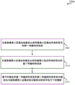
fig. 3 is a flow diagram of a method for hierarchical modulation of content in a base station, in accordance with various examples;
fig. 4 illustrates a block diagram of an apparatus that may be used for hierarchical modulation, in accordance with various examples;
fig. 5 is an illustration of modulation schemes for a base layer, an enhancement layer, and a resulting transmission, in accordance with various examples;
fig. 6 is an illustration of a hierarchical modulation scheme and the likelihood of successfully decoding an enhancement layer at different User Equipments (UEs) that may be served by an evolved node B (eNB);
fig. 7 illustrates a hierarchical modulation environment in accordance with various examples;
fig. 8 illustrates another hierarchical modulation environment in accordance with various examples;
fig. 9 illustrates another hierarchical modulation environment in accordance with various examples;
fig. 10 illustrates a block diagram of an apparatus that may be used for hierarchical modulation, in accordance with various examples;
fig. 11 is a flow diagram of a method for hierarchical modulation of content in a base station, in accordance with various examples;
fig. 12 is a flow diagram of another method for hierarchical modulation of content in a base station, in accordance with various examples;
fig. 13 illustrates a block diagram of an apparatus that may be used for hierarchical modulation and interference cancellation, according to various examples;
fig. 14 is a flow diagram of a method for hierarchical modulation of content and interference cancellation in a user equipment, according to various examples;
fig. 15 illustrates another block diagram of an apparatus that may be used for hierarchical modulation and interference cancellation, in accordance with various examples;
fig. 16 illustrates a block diagram of an apparatus that may be used for hierarchical modulation at a user equipment, in accordance with various examples;
fig. 17 is a flow diagram of a method for hierarchical modulation of content in a user equipment, according to various examples;
fig. 18 illustrates a hierarchical modulation environment in accordance with various examples;
fig. 19 illustrates another block diagram of an apparatus that may be used for hierarchical modulation at a user equipment, in accordance with various examples;
fig. 20A and 20B illustrate block diagrams of apparatuses that may be used for hierarchical modulation and interference cancellation at a base station, according to various examples;
fig. 21 is a flow diagram of a method for hierarchical modulation of content and interference cancellation in a base station, in accordance with various examples;
fig. 22 illustrates a wireless communication system and an interference cancellation environment, in accordance with various examples;
fig. 23 illustrates time division duplex uplink/downlink configurations in a wireless communication system, in accordance with various examples;
fig. 24 is a flow diagram of a method for inter-cell interference mitigation, according to various examples;
fig. 25 is a block diagram of an apparatus that may be used for inter-cell interference mitigation at a user equipment, in accordance with various examples;
fig. 26 is another flow diagram of a method for inter-cell interference mitigation, in accordance with various examples;
fig. 27 illustrates a wireless communication system and an interference mitigation environment, in accordance with various examples;
fig. 28 is another flow diagram of a method for inter-cell interference mitigation, in accordance with various examples;
fig. 29 is another flow diagram of a method for inter-cell interference mitigation, in accordance with various examples;
fig. 30 is a block diagram of an apparatus that may be used for inter-cell interference mitigation at a user equipment, in accordance with various examples;
fig. 31 illustrates another wireless communication system and interference mitigation environment, in accordance with various examples;
fig. 32 is another flow diagram of a method for inter-cell interference mitigation, in accordance with various examples;
fig. 33 is a block diagram of another apparatus that may be used for inter-cell interference mitigation at a user equipment, in accordance with various examples;
fig. 34 illustrates another wireless communication system and interference cancellation environment, in accordance with various examples;
fig. 35 is a block diagram of an apparatus that may be used for inter-radio interference cancellation at a user equipment, according to various examples;
fig. 36 is a flow diagram of a method for inter-radio interference cancellation according to various examples;
fig. 37 is a flow diagram of another method for inter-radio interference cancellation, according to various examples;
fig. 38 is a block diagram illustrating an example of a base station architecture according to various examples;
fig. 39 shows a block diagram illustrating an example of a UE architecture according to various examples;
fig. 40 shows a block diagram illustrating an example of a multiple-input multiple-output (MIMO) communication system, in accordance with various examples;
fig. 41 is a flow diagram of a wireless communication method according to various examples;
fig. 42 is a flow diagram of another method of wireless communication, according to various examples;
fig. 43 is a flow diagram of another method of wireless communication, according to various examples;
fig. 44 is a flow diagram of another method of wireless communication, according to various examples;
fig. 45 is a flow diagram of another method of wireless communication, according to various examples; and
fig. 46 is a flow diagram of another method of wireless communication, according to various examples.
Detailed Description
Techniques for interference mitigation and hierarchical modulation within a wireless communication system are described. A base station (e.g., an evolved node B (eNB)) and/or a User Equipment (UE) may be configured to operate within a wireless communication system and may transmit/receive wireless communications on a base modulation layer and an enhancement modulation layer modulated on the base modulation layer. Thus, concurrent non-orthogonal data streams may be provided to the same or different UEs, and each modulation layer may be used to transmit content that may be selected based on a particular deployment and/or channel conditions. In examples, various interference mitigation techniques may be implemented to compensate for interfering signals received within a cell, to compensate for interfering signals received from other cells, and/or to compensate for interfering signals received from other radios that may operate in adjacent wireless communication networks.
In some examples, concurrent non-orthogonal wireless communication data streams may be provided from a base station to a UE through hierarchical modulation in which first content may be selected for transmission on a base modulation layer and different content may be selected for transmission on an enhancement modulation layer. The base modulation layer content may be modulated onto the base modulation layer and subsequently the enhancement layer content may be modulated onto the enhancement modulation layer. The enhanced modulation may be superimposed on the base modulation layer and transmitted to one or more UEs. In various examples, a UE may transmit multiple hierarchical layers to a base station in a similar manner.
A UE receiving both the base modulation layer and the enhancement modulation layer may decode content received on the base modulation layer and then perform interference cancellation to cancel signals of the base modulation layer. The UE may then decode the content received on the enhancement modulation layer.
In some examples, the base modulation layer may support transmissions with a higher likelihood of transmission success, and the base modulation layer may be used to transmit content with a relatively lower error threshold. In some examples, the enhancement modulation layer may support transmissions having a relatively low likelihood of transmission success and may be used to transmit content having a relatively high error threshold.
According to various examples, a UE and a base station may perform interference mitigation on a received signal. Such interference mitigation may be performed on signals generated from within a serving cell associated with the UE and the base station (intra-cell interference), signals from neighboring cells of the serving cell (inter-cell interference), and/or signals from adjacent communication channels (inter-radio interference).
The techniques described herein are not limited to Long Term Evolution (LTE) and may also be used for various wireless communication systems such as CDMA, TDMA, FDMA, OFDMA, SC-FDMA, and other systems. The terms "system" and "network" are often used interchangeably. A CDMA system may implement a radio technology such as CDMA2000, Universal Terrestrial Radio Access (UTRA), and so on. CDMA2000 covers IS-2000, IS-95 and IS-856 standards. IS-2000 releases 0 and A are often referred to as CDMA 20001X, 1X, etc. IS-856(TIA-856) IS often referred to as CDMA 20001 xEV-DO, High Rate Packet Data (HRPD), etc. UTRA includes wideband CDMA (wcdma) and other CDMA variants. TDMA systems may implement radio technologies such as global system for mobile communications (GSM). OFDMA systems may implement radio technologies such as Ultra Mobile Broadband (UMB), evolved UTRA (E-UTRA), IEEE 802.11(Wi-Fi), IEEE 802.16(WiMAX), IEEE 802.20, Flash-OFDM, etc. UTRA and E-UTRA are parts of the Universal Mobile Telecommunications System (UMTS). LTE and LTE-advanced (LTE-A) are new UMTS releases that use E-UTRA. UTRA, E-UTRA, UMTS, LTE-A, and GSM are described in literature from an organization named "third Generation partnership project" (3 GPP). CDMA2000 and UMB are described in documents from an organization named "third generation partnership project 2" (3GPP 2). The techniques described herein may be used for both the above-mentioned systems and radio technologies, as well as for other systems and radio technologies. However, the following description describes an LTE system for purposes of example, and LTE terminology is used in much of the description below, although the techniques may also be applied to applications other than LTE applications.
Accordingly, the following description provides examples and does not limit the scope, applicability, or configuration set forth in the claims. Changes may be made in the function and arrangement of elements discussed without departing from the spirit and scope of the disclosure. Various embodiments may omit, substitute, or add various procedures or components, as appropriate. For example, the described methods may be performed in an order different than described, and various steps may be added, omitted, or combined. Furthermore, features described with respect to certain embodiments may be combined in other embodiments.
Referring initially to fig. 1, an example of a wireless communication system or network 100 is illustrated. The wireless communication system 100 includes a base station (or cell) 105, a communication device 115, and a core network 130. The base stations 105 may communicate with the communication devices 115 under the control of a base station controller (not shown), which may be part of the core network 130 or the base stations 105 in various embodiments. The base stations 105 may communicate control information and/or user data with the core network 130 over backhaul links 132. In various embodiments, the base stations 105 may communicate with each other directly or indirectly over backhaul links 134, which backhaul links 134 may be wired or wireless communication links. The wireless communication system 100 may support operation on multiple carriers (waveform signals of different frequencies). A multi-carrier transmitter can transmit modulated signals on the multiple carriers simultaneously. For example, each communication link 125 may be a multi-carrier signal modulated according to the various radio technologies described above. Each modulated signal may be sent on a different carrier and may carry control information (e.g., reference signals, control channels, etc.), overhead information, data, and so on.
The base station 105 may communicate wirelessly with the device 115 via one or more base station antennas. Each of the base station 105 sites may provide communication coverage for a respective coverage area 110. In some embodiments, the base station 105 may be referred to as a base transceiver station, a radio base station, an access point, a radio transceiver, a Basic Service Set (BSS), an Extended Service Set (ESS), a node B, an evolved node B (eNB), a home node B, a home evolved node B, or some other suitable terminology. The coverage area 110 of a base station may be divided into sectors (not shown) that form only a portion of the coverage area. The wireless communication system 100 may include different types of base stations 105 (e.g., macro and/or small cell base stations). There may be overlapping coverage areas of different technologies.
In some examples, the wireless communication system 100 is an LTE/LTE-a network that supports hierarchical modulation and interference cancellation modes of operation. The wireless communication system 100 may be a heterogeneous LTE/LTE-a network in which different types of enbs provide coverage for various geographic regions. For example, each eNB105 may provide communication coverage for a macro cell, pico cell, femto cell, and/or other type of cell. Small cells, such as picocells, femtocells, and/or other types of cells, may include low power nodes or LPNs. A macro cell generally covers a relatively large geographic area (e.g., an area with a radius of several kilometers) and may allow unrestricted access by UEs with service subscriptions with the network provider. A small cell will generally cover a relatively small geographic area and may allow unrestricted access by UEs with service subscriptions with the network provider and/or restricted access by UEs associated with the small cell (e.g., UEs in a Closed Subscriber Group (CSG), UEs of users in the home, and the like). The eNB for a macro cell may be referred to as a macro eNB. An eNB for a small cell may be referred to as a small cell eNB, a femto eNB, or a home eNB. An eNB may support one or more (e.g., two, three, four, etc.) cells.
The core network 130 may communicate with the eNB105 via a backhaul link 132 (e.g., S1, etc.). The enbs 105 may also communicate with one another, directly or indirectly, e.g., via backhaul link 134 (e.g., X2, etc.) and/or via backhaul link 132 (e.g., through core network 130). The wireless communication system 100 may support synchronous or asynchronous operation. For synchronous operation, each eNB may have similar frame and/or gating timing, and transmissions from different enbs may be approximately aligned in time. For asynchronous operation, each eNB may have different frame and/or gating timing, and transmissions from different enbs may not be aligned in time. The techniques described herein may be used for synchronous or asynchronous operations.
The communication links 125 shown in the wireless communication system 100 may include Uplink (UL) transmissions from the mobile devices 115 to the base stations 105, and/or Downlink (DL) transmissions from the base stations 105 to the mobile devices 115. DL transmissions may also be referred to as forward link transmissions, while UL transmissions may also be referred to as reverse link transmissions. According to various examples, one or both of the UL and DL transmissions may include multiple hierarchical modulation layers, where one or more enhancement modulation layers may be superimposed onto a base modulation layer. The base modulation layer may be decoded to obtain content modulated on the base modulation layer. The enhancement modulation layer(s) may be decoded by eliminating the base modulation layer (and other lower modulation layers, if any) and decoding the resulting signal.
In some examples of wireless communication system 100, various interference cancellation techniques may be employed, including intra-cell interference cancellation, inter-cell interference cancellation, and inter-radio interference cancellation. The base stations 105 and UEs 115 may support one or more of these or similar modes of operation. OFDMA communication signals may be used in the communication link 125 for LTE downlink transmissions in the unlicensed spectrum, while SC-FDMA communication signals may be used in the communication link 125 for LTE uplink transmissions. Interference cancellation may be performed for the uplink and downlink. Inter-radio interference may be addressed by the base station 105 as well as the UE 115. Additional details regarding hierarchical modulation and/or interference cancellation in systems, such as wireless communication system 100, and implementation of other features and functions related to operation in such systems are provided below with respect to fig. 2-46.
Fig. 2 illustrates a wireless communication system 200 in which an eNB 105-a may communicate with one or more UEs 115 using hierarchical modulation. The wireless communication system 200 may, for example, illustrate aspects of the wireless communication system 100 illustrated in fig. 1. In the example of FIG. 2, an eNB 105-a may communicate with a number of UEs 115-a, 115-b, and 115-c within a coverage area 110-a of the eNB 105-a. In this example, multiple modulation layers may be used for wireless communication, where a base modulation layer and one or more enhancement modulation layers may be concurrently transmitted between the eNB 105-a and the UE 115. According to various examples, the base modulation layer may provide higher reliability communication between the eNB 105-a and the UE115, resulting in a higher likelihood that the UE115 within the coverage area 110-a will be able to decode content transmitted on the base modulation layer without requiring retransmission of the content. According to various examples, the enhanced modulation layer may provide relatively lower reliability communication between the eNB 105-b and the UE115 than the base modulation layer. Thus, transmissions on the enhancement modulation layer may have a higher likelihood of requiring retransmission for a receiver to successfully decode content transmitted on the enhancement modulation layer. The modulation and transmission of the base modulation layer and the enhancement modulation layer will be described in more detail below with reference to fig. 5 and 6.
As mentioned, the enhanced modulation layer may have a lower likelihood of successful reception relative to the base modulation layer, where the likelihood of successful reception depends largely on the channel conditions between the eNB 105-a and the UE 115. In some deployments, such as illustrated in fig. 2, UE115-a and UE 115-b may be relatively close to eNB 105-a in area 205, while UE115-c may be closer to the cell edge where eNB 105-a covers area 110-a. If it is determined that the UEs 115-a and 115-b located in the area 205 have channel conditions conducive to hierarchical modulation, the eNB 105-a may signal to the UEs 115-a and 115-b that such communication may be employed. In such a case, communication link 125-a may include both base and enhancement modulation layers, and UEs 115-a and 115-b may support communication on each hierarchical modulation layer. In this example, a UE115-c closer to the cell edge of coverage area 110-a and outside of area 205 may be signaled to communicate using a base modulation layer in communication link 125-b. While communication link 125-b may still be communicated with both the base modulation layer and the enhancement modulation layer, UE115-c may not attempt to decode the enhancement modulation layer due to the relatively low likelihood of successful reception and decoding of content modulated on the enhancement modulation layer.
As mentioned above, the base modulation layer in such a deployment may provide a relatively high reliability communication link between the UE115 and the eNB 105-a. According to some examples, content transmitted using the base modulation layer may be selected as content more desirable to transmit at a lower error rate, and content transmitted using the enhancement modulation layer may be selected as content less sensitive to transmission error rate. For example, the base modulation layer may be used to transfer high priority or latency sensitive content. In some examples, the base modulation layer may include control information, such as uplink or downlink grant information, acknowledgement information regarding previous transmissions, and/or other control signaling, in addition to user data. In such examples, the enhancement modulation layer may be used to transmit user data that has a lower sensitivity to transmission errors.
In other examples, the base modulation layer may include latency-sensitive unicast data for a particular UE115, and the enhancement modulation layer may include latency-insensitive unicast data. For example, a determination of whether to use the base modulation layer or the enhancement modulation layer for transmitting the unicast data may be made based on a quality of service (QoS) associated with the different unicast data. For example, data with high QoS requirements may be transmitted using a base modulation layer, and data with best effort QoS requirements may be transmitted using an enhancement modulation layer. In still further examples, the base modulation layer may be used to transmit broadcast data from the eNB 105-a and the enhancement modulation layer may be used to transmit unicast data associated with a particular UE 115.
In some examples, the base modulation layer may be transmitted without requiring an acknowledgement that the transmitted data was received. For example, the base modulation layer content may be transmitted without requiring hybrid automatic repeat request (HARQ) acknowledgement/negative acknowledgement of the received content. In some examples, the error rate associated with the base modulation layer may be about 1%, and the error rate associated with the enhancement modulation layer may be higher than 1% (such as 10%). Thus, successful receipt of content transmitted using the enhancement modulation layer may require reliance on retransmission procedures, while the error rate associated with the base modulation layer may provide confidence that retransmission is not required to achieve successful content transmission.
In cases where successful reception of the enhancement modulation layer is less likely (such as for the UE 115-c), the base modulation layer alone may be used for communication between the UE115-c and the eNB 105-a. As such, communications with different UEs 115 may be selectively adapted based on channel conditions, with UEs 115 having appropriate channel conditions being signaled to receive data on multiple hierarchical modulation layers transmitted concurrently, thereby enhancing data rates to such UEs 115. Likewise, communications with UEs 115 having relatively poor channel conditions may be maintained at reliably maintained data rates through the base modulation layer. In some examples, the base modulation layer may be used to transmit one or more of a physical downlink control channel (PDCCH or ePDCCH), a Physical Downlink Shared Channel (PDSCH), a Physical Multicast Channel (PMCH), or high priority data based on UE reference signals. In various examples, the enhancement modulation layer may be used to transmit one or more of a UE reference signal based PDSCH or ePDSCH, or lower priority data. Similarly as discussed above, the determination of high priority data and low priority data may be made based on QoS parameters associated with the data.
Referring now to fig. 3, a flow diagram conceptually illustrating an example of a method of wireless communication is described, in accordance with aspects of the present disclosure. For clarity, the method 300 is described below with reference to some of the base stations, enbs 105, and/or UEs 115 described with respect to fig. 1 and/or 2. In one example, an eNB or UE may execute one or more sets of codes to control the functional elements of the eNB or UE to perform the functions described below.
At block 305, content is identified for transfer over a base modulation layer. For example, the eNB may identify high priority content or latency sensitive content, similar to that discussed above. Additionally, as mentioned above, the eNB may identify unicast content to the UE to transmit to the UE based on whether the UE is able to reliably receive one or more enhancement modulation layers, and may identify content for transmission on the base modulation layer according to such a determination. In some examples, the UE may identify content to be transmitted to the eNB on the base modulation layer based on similar criteria. In some examples, the UE may receive signaling from the eNB indicating that certain content is to be transmitted on the base modulation layer.
At block 310, content is identified for transmission on an enhancement modulation layer. For example, similar to that discussed above, the eNB may identify lower priority content or latency insensitive content. Additionally, as mentioned above, the eNB may identify unicast content to the UE to transmit to the UE based on whether the UE is able to reliably receive the enhancement modulation layer, and may identify content for transmission on the enhancement modulation layer according to such a determination. In various examples, the UE may identify content to transmit to the eNB on the enhancement modulation layer based on similar criteria and/or may receive signaling from the eNB indicating that certain content is to be transmitted on the enhancement modulation layer.
At block 315, the base layer content is modulated onto a base modulation layer. Such modulation may be, for example, binary phase shift keying (BSPK) modulation, Quadrature Phase Shift Keying (QPSK), or 16 quadrature amplitude modulation (16QAM) modulation, to name but three examples. At block 320, enhancement layer content is modulated onto an enhancement modulation layer. Similar to the base modulation layer modulation, such modulation may be binary phase shift keying (BSPK) modulation, Quadrature Phase Shift Keying (QPSK), or 16 quadrature amplitude modulation (16QAM) modulation, to name but three examples.
At block 325, the enhancement modulation layer is superimposed onto the base modulation layer. Such superposition results in a superimposed constituent constellation, in accordance with the modulation used at each of the base modulation layer and the enhancement modulation layer. In the example where QPSK is used for the base modulation layer and QPSK is used for the enhancement modulation layer, the result is a shaped 16 QAM. In the example where the base modulation layer uses QPSK and the enhancement modulation layer uses 16QAM, the result is a shaped 64QAM constellation. Further, in the example where the base modulation layer uses 16QAM and the enhancement modulation layer uses 16QAM, the result is a shaped 256QAM constellation. Finally, at block 330, the superimposed base modulation layer and enhancement modulation layer are transmitted. As mentioned above, a receiver (such as a UE or eNB receiving the transmitted signal) may decode the received signal to obtain base modulation layer content, cancel interference associated with the base modulation layer to obtain an enhancement modulation layer, and decode the enhancement modulation layer to obtain enhancement modulation layer content.
Fig. 4 is a block diagram conceptually illustrating a device (such as an eNB) for use in wireless communications, according to aspects of the present disclosure. In some examples, the device 405 may be an example of one or more aspects of a base station or eNB105 described with reference to fig. 1 and/or 2. The device 405 may also be a processor. The apparatus 405 may include a receiver module 410, an eNB hierarchical modulation module 420, and/or a transmitter module 430. Each of these components may be in communication with each other.
The components of device 405 may be implemented individually or collectively with one or more Application Specific Integrated Circuits (ASICs) adapted to perform some or all of the applicable functions in hardware. Alternatively, the functions may be performed by one or more other processing units (or cores), on one or more integrated circuits. In other examples, other types of integrated circuits (e.g., structured/platform ASICs, Field Programmable Gate Arrays (FPGAs), and other semi-custom ICs) that may be programmed in any manner known in the art may be used. The functions of each unit may also be implemented, in whole or in part, with instructions embodied in a memory, formatted to be executed by one or more general or special purpose processors.
In some examples, the receiver module 410 may be or include a Radio Frequency (RF) receiver, such as an RF receiver operable to receive transmissions on two or more hierarchical modulation layers. The receiver module 410 may be used to receive various types of data and/or control signals (i.e., transmissions) over one or more communication links of a wireless communication system, such as one or more communication links 125 of the wireless communication systems 100 and/or 200 described with reference to fig. 1 and/or 2.
In some examples, the transmitter module 430 may be or include an RF transmitter, such as an RF transmitter operable to transmit on two or more hierarchical modulation layers (e.g., through a base modulation layer and one or more enhancement modulation layers). The transmitter module 430 may be used to transmit various types of data and/or control signals (i.e., transmissions) over one or more communication links of a wireless communication system, such as one or more communication links 125 of the wireless communication system 100 and/or 200 described with reference to fig. 1 and/or 2.
In some examples, when operating in a wireless communication system that supports transmission on two or more hierarchical modulation layers, the eNB hierarchical modulation module 420 may configure multiple hierarchical modulation layers and determine content to transmit for the device 405 on each hierarchical modulation layer. For example, the eNB hierarchical modulation module 420 may configure the apparatus 405 to determine content for transmission on each hierarchical modulation layer, modulation of the content on each hierarchical modulation layer, and superposition of the hierarchical modulation layers for transmission by the transmission module 430, such as described above with reference to fig. 1-3 and as will be described below for various examples in fig. 5-46, for example.
In certain examples, the eNB hierarchical modulation module 420 may receive a signal including a plurality of hierarchical modulation layers from the receiver module 410. In such a case, eNB hierarchical modulation module 420 may decode the base modulation layer, cancel interference from the base modulation layer from the received signal, and decode the resulting signal to obtain content from the enhancement modulation layer. In some examples, there may be two or more enhancement modulation layers, in which case eNB hierarchical modulation module 420 may perform successive interference cancellation and decoding for each successive modulation layer. Further, the eNB hierarchical modulation module 420 may, in various examples, determine one or more parameters associated with each hierarchical modulation layer and may provide signaling to one or more UEs that are to transmit and/or receive transmissions on multiple hierarchical modulation layers, such as described above with reference to fig. 1-3 and as will be described below for various examples in fig. 5-46, for example.
As discussed above, in various examples, a transmission from a UE, eNB, or other device (such as UE115, eNB105, and/or device 405 of FIGS. 1, 2, and/or 4) may include multiple hierarchical modulation layers FIG. 5 illustrates examples 500 of hierarchical modulation layers and resulting transmissions from superimposed hierarchical modulation layersB:XB∈CB}. similarly, lower QoS enhancement modulation layer 510 may use QPSK encoding and is denoted as { β X ×)E:XE∈CE}. the resulting hierarchical constellation 515 formed from the superposition of the constituent base modulation layer constellation 505 and the enhancement layer constellation 510 may be denoted as C ═ X ═ α XB+βXEThe shaped 16QAM constellation of. It will be appreciated that different modulation schemes may be used for the base modulation layer and/or the enhancement modulation layer, resulting in corresponding changes in the hierarchical constellation. For example, the base modulation layer may use QPSK and the enhancement modulation layer may use 16QAM, thereby resulting in a shaped 64QAM hierarchical constellation. In other examples, the base modulation layer may use 16QAM and the enhancement modulation layer may use 16QAM, thereby resulting in a shaped 256QAM hierarchical constellation. Further, in a similar manner, additional enhancement modulation layers may be superimposed onto the hierarchical constellation to provide three or more hierarchical modulation layers.
As mentioned, the base modulation layer may be used to provide a high QoS data stream between the UE and the eNB, and the enhancement modulation layer may be used to provide a lower QoS data stream between the UE and the eNB. In some cases, as mentioned, channel conditions between the UE and the eNB may not support transmission and decoding of the enhanced modulation layer, and communications with UEs having such channel conditions may be performed using the base modulation layer. Fig. 6 illustrates an example 600 of different UEs 115 that may receive a hierarchical modulation signal 605. Within signal 605 are several clusters 610 representing base modulation layers, and within each cluster 610 there may be several individual points representing hierarchical modulation layers. The first UE 115-b may have relatively good channel conditions and may receive the hierarchical modulation signal 605 as the received signal 615. Within the received signal 615, the first UE 115-b-1 may be able to distinguish between clusters 610-b and individual points within each cluster 610-b. Thus, for example, the first UE 115-b-1 may be within the area 205 as illustrated in fig. 2.
The second UE 115-c-1 in this example may be closer to the cell edge of the serving cell transmitting the hierarchical modulation signal 605 and may have a relatively poor channel quality, resulting in a received signal 620 in which clusters 610-c may be differentiated but individual points may not. Thus, the second UE 115-c-1 may reliably receive and decode the base modulation layer, but may not reliably receive and decode the enhancement modulation layer. In some examples, the serving cell eNB may use the base modulation layer to transmit data to the second UE 115-c-1 and the enhancement modulation layer to transmit data to the first UE 115-b-1. In other examples, such as discussed above, the base modulation layer may be used to transmit low latency data, high priority data, control data, and the like, and the enhancement modulation layer may be used to transmit latency insensitive data, low priority data, user data, and the like.
According to some examples, the log-likelihood ratio (LLR) of the base modulation layer may be calculated according to the following calculation:

wherein the LLRB,kBase modulation layer LLR, b being bit kB(k) Is the base modulation layer bit k for symbol x, and C is the constellation of the modulation scheme of the base modulation layer.
In some examples, the enhancement modulation layer may be decoded using parallel decoding or using serial decoding (where interference cancellation is performed on the base modulation layer). In examples using parallel decoding, the grey map may be used and the LLRs may be calculated according to the following calculation:

wherein the LLRE,kEnhancement modulation layer LLR, b being bit kE(k) Is the enhancement modulation layer bit k of symbol x and C is the constellation of the shaped modulation schemes of the superimposed base and enhancement modulation layers.
In examples using serial decoding (where interference cancellation is performed on the base modulation layer), the LLRs may be calculated according to the following calculation:

wherein the LLRE,kEnhancement modulation layer LLR, b being bit kE(k) Enhancement modulation layer bit k being symbol x, C is the constellation of the enhancement layer modulation scheme, and yEIs the enhancement modulation layer reconstructed after interference cancellation of the combined base and enhancement modulation layer signals.
As discussed above, the base modulation layer and the enhancement modulation layer may be used to transmit different content based on one or more of a number of different factors. Such factors may include, for example, system deployment, traffic requirements, the type of information contained in the content to be transmitted, channel conditions, the number of UEs capable of receiving multiple modulation layers, and/or the number of UEs capable of receiving only a base modulation layer, to name a few examples. Fig. 7 illustrates a wireless communication system 700 in which an eNB 115-b may communicate with a UE115-d using hierarchical modulation. Although only one UE115-d is illustrated, it will be readily appreciated that the eNB 105-b may be in communication with multiple UEs. The wireless communication system 700 may, for example, illustrate aspects of the wireless communication systems 100 and/or 200 illustrated in fig. 1 and/or 2. In this example, multiple modulation layers may be used for wireless communication, where a base modulation layer 705 and an enhancement modulation layer 710 may be concurrently transmitted between the eNB 105-b and the UE 115-d. Although a single enhancement modulation layer 710 is illustrated in fig. 7, other examples may include more than one enhancement modulation layer. The enhancement modulation layer 710 may be superimposed on the base modulation layer 705 and transmitted in a single communication link between the eNB 105-b to the UE115-d, such as in the manner described above with reference to fig. 3-6.
According to this example, base modulation layer 705 may provide higher reliability communication between eNB 105-b and UE115-d, resulting in a relatively higher confidence that UE115-d may successfully receive and decode base modulation layer 705. In this example, the UE115-d does not transmit an Acknowledgement (ACK) or Negative Acknowledgement (NACK) of receipt of the transmission on the base modulation layer (such as in accordance with HARQ techniques). Removal of such feedback may enhance capacity at the base modulation layer since there is less overhead associated with HARQ ACK/NACK transmissions and associated retransmissions. Due to the relatively high reliability of the base modulation layer 705, content may be selected for transmission over the base modulation layer, which may benefit from the high reliability and reduced latency of the base modulation layer 705 transmissions. For example, as discussed above, the base modulation layer 705 may be selected to communicate high priority content, latency sensitive content, and/or control/signaling information from the eNB 105-b to the UE 115-d.
According to various examples, the enhanced modulation layer 710 may provide relatively lower reliability communications between the eNB 105-b and the UE115-d than the base modulation layer 705. Thus, the UE115-d may perform HARQ techniques on transmissions of the enhancement modulation layer 710 such that transmissions that are not successfully received and decoded may be retransmitted by the eNB 105-b. According to some examples, base modulation layer 705 may have an error rate of about 1% and enhancement modulation layer 710 may have an error rate of about 10%. As mentioned above, in some examples, the eNB 105-b may identify the first content for transmission on the base modulation layer 705.
In some examples, the first content may be associated with a first error rate threshold that defines an error rate required or desired for the first content in the initial transmission. The first error rate threshold may be determined based on, for example, the type of information contained in the first content. The eNB 105-b may also identify the second content for transmission on the enhancement modulation layer 710. In some examples, the second content may be associated with a second error rate threshold that is higher than the first error rate threshold. The second error rate threshold may be determined, for example, based on the type of information contained in the second content. For example, the first content may include high priority content and the second content may include lower priority content. As used herein, the term "error rate threshold" may include a target or desired reliability threshold, or may include another reliability or error rate metric associated with the data.
In other examples, the first content may include control information that may be used by the UE115-d for communication with the eNB 105-b. For example, the control information may include scheduling grant information, acknowledgement information, and/or signaling information, and the control information may be transmitted on the base modulation layer 705 using PDCCH. The second content may include, for example, user data that may be transmitted on the enhanced modulation layer 710 using PDSCH. In still other examples, the first content may include latency-sensitive unicast data to the UE115-d and the second content may include best-effort unicast data to the UE115-d or to a different UE. Latency sensitive unicast data may be transmitted on base modulation layer 705 using PDSCH, for example, and best effort unicast data may be transmitted on enhancement modulation layer 710 using PDSCH.
Similar to that discussed above with reference to fig. 3-6, the eNB 105-b may modulate the first content on the base modulation layer 705 and the second content on the enhancement modulation layer 710. The eNB 105-b may then superimpose an enhancement modulation layer 710 on the base modulation layer 705 and transmit the superimposed base and enhancement modulation layers 705 and 710 to the UE 115-d. Thus, in this example, both base modulation layer 705 and enhancement modulation layer 710 include content to be transmitted to the same UE (i.e., UE 115-d). In other examples, the contents of base modulation layer 705 may be transmitted to a different UE than the UE to which the contents of enhancement modulation layer 710 are transmitted. The UE115-d (and other UEs operating in system 700) may receive control signaling from the eNB 105-b indicating which of the base modulation layer 705 and the enhancement modulation layer 710 to decode for a particular time period (e.g., one or more subframes indicated in a downlink grant provided to the UE115-d via the PDCCH).
Referring now to fig. 8, a wireless communication system 800 is illustrated in which an eNB 105-c may be in communication with a UE115-e and a UE 115-f using hierarchical modulation. The wireless communication system 800 may, for example, illustrate aspects of the wireless communication systems 100, 200, and/or 700 illustrated in fig. 1, 2, and/or 7. In this example, similar to the above, multiple modulation layers may be used for wireless communication, where the base modulation layer 805 and the enhancement modulation layer 810 may be concurrently transmitted between the eNB 105-c and the UEs 115-e and 115-f. In this example, base modulation layer 805 may include broadcast data to be transmitted to a plurality of different UEs (such as UE115-e and UE 115-f).
In this example, enhancement modulation layer 810 may be superimposed on base modulation layer 805 and include unicast data for UEs 115-e. The enhancement modulation layer and the base modulation layer may be transmitted in a single communication link between the eNB 105-c to the UE115-e in a manner such as described above with reference to fig. 3-6. In this example, UE 115-f may ignore enhancement modulation layer 810 based on enhancement modulation layer 810 not including content for UE 115-f, even though UE 115-f may have sufficient channel quality to receive and decode enhancement modulation layer 810. In some examples, the eNB 105-c may provide signaling to the UEs 115-e and 115-f indicating that the first UE115-e is scheduled to receive unicast data via the enhanced modulation layer 810. A second UE 115-f that has not received a downlink grant on the enhancement modulation layer 810 may thus ignore the enhancement modulation layer 810 and decode the information contained in the base modulation layer 805.
In some examples, broadcast data provided on base modulation layer 805 may be transmitted using a Physical Multicast Channel (PMCH), and unicast data provided on enhancement modulation layer 810 may be transmitted using PDSCH. In some examples, UEs 115-e and 115-f receive broadcast data on the base modulation layer and do not transmit an acknowledgement that the broadcast data was received. In various examples, a UE115-e receiving unicast data via the enhanced modulation layer 810 may perform a HARQ technique on the received unicast data and transmit an ACK/NACK for the receipt of the unicast data.
Referring now to fig. 9, a wireless communication system 900 is illustrated in which an eNB 105-d may be in communication with a UE115-g and a UE 115-h using hierarchical modulation. The wireless communication system 900 may, for example, illustrate aspects of the wireless communication systems 100, 200, 700, and/or 800 illustrated in fig. 1, 2, 7, and/or 8. In this example, similar to the above, multiple modulation layers may be used for wireless communication, where base modulation layer 905 and enhancement modulation layer 910 may be concurrently transmitted between eNB 105-d and UEs 115-g and 115-h. In this example, the base modulation layer 905 may include first content including unicast data transmitted to the first UE115-g, and the enhancement modulation layer 910 may be superimposed on the base modulation layer 905 and include second content including unicast data for the second UE 115-h.
In this example, the second UE 115-h may have relatively good channel conditions that allow the UE 115-h to receive and decode the enhancement modulation layer 910. eNB 105-d may thus schedule UE 115-h to receive downlink content using enhancement modulation layer 910, and UE 115-h may perform interference cancellation on the received transmission to cancel interference from base modulation layer 905 and decode enhancement modulation layer 910. Thus, by using hierarchical modulation techniques, multiple data streams may be concurrently transmitted to different UEs 115-g and 115-h, thereby enhancing utilization of the wireless communication system 900.
In some examples, the eNB 105-d may provide signaling to the UEs 115-g and 115-h indicating that the first UE115-g is scheduled to receive unicast data via the base modulation layer 905 and that the second UE 115-h is scheduled to receive unicast data via the enhancement modulation layer 910. In some examples, unicast data provided to each of UEs 115-g and 115-h may be transmitted using PDSCH transmitted on respective base modulation layer 905 or enhanced modulation layer 910. In some examples, UEs 115-g and 115-h may perform HARQ techniques on received unicast data and transmit an ACK/NACK for receipt of the unicast data.
Referring now to fig. 10, a block diagram 1000 illustrates a device 405-a for use in wireless communications in accordance with various aspects of the present disclosure. In some examples, device 405-a may be an example of one or more aspects of base station or eNB105 and/or device 405 described with reference to fig. 1, 2, 4, 7, 8, and/or 9. The device 405-a may also be a processor. The device 405-a may include a receiver module 410-a, an eNB hierarchical modulation module 420-a, and/or a transmitter module 430-a. Each of these components may be in communication with each other.
The components of device 405-a may be implemented individually or collectively using one or more ASICs adapted to perform some or all of the applicable functions in hardware. Alternatively, the functions may be performed by one or more other processing units (or cores), on one or more integrated circuits. In other examples, other types of integrated circuits (e.g., structured/platform ASICs, FPGAs, and other semi-custom ICs) that can be programmed in any manner known in the art may be used. The functions of each unit may also be implemented, in whole or in part, with instructions embodied in a memory, formatted to be executed by one or more general or special purpose processors.
In some examples, the receiver module 410-a may be an example of the receiver module 410 of fig. 4. The receiver module 410-a may be or include an RF receiver, such as an RF receiver operable to receive transmissions on two or more hierarchical modulation layers. In some examples, transmitter module 430-a may be an example of transmitter module 430 of fig. 4. Transmitter module 430-a may be or include an RF transmitter, such as an RF transmitter operable to transmit data on two or more hierarchical modulation layers. In some examples, RF transmitter 430-a may include a single transmitter or a single transmitter in each transmit/receive chain. The transmitter module 430-a may be used to transmit various types of data and/or control signals (i.e., transmissions) over one or more communication links of a wireless communication system including two or more hierarchical modulation layers, such as one or more communication links 125 of the wireless communication system 100, 200, 700, 800, and/or 900 described with reference to fig. 1, 2, 7, 8, and/or 9.
The eNB hierarchical modulation module 420-a may be an example of the eNB hierarchical modulation module 420 described with reference to fig. 4 and may include a base/enhancement modulation layer content determination module 1055, a content modulation module 1060, a parameter determination module 1060, and a superposition module 1070. Each of these components may be in communication with each other.
In some examples, the base/enhancement modulation layer content determination module 1055 may determine content to be transmitted from the device 405-a using a base modulation layer and content to be transmitted from the device 405-a using an enhancement modulation layer, such as described above with reference to fig. 1-9, for example. The content modulation module 1060 may modulate the determined content onto the appropriate base modulation layer or enhancement modulation layer. The parameter determination module 1065 may determine one or more of various parameters related to channel conditions and parameters to be used in hierarchical modulation, such as a transmission energy ratio between the base modulation layer and the enhancement modulation layer.
In some examples, parameter determination module 1065 may determine a channel quality associated with the UE based on Channel State Information (CSI) received from the UE and determine whether the UE channel conditions support hierarchical modulation. The parameter determination module 1065 may calculate a transmission energy ratio between the base modulation layer and the enhancement modulation layer based on the CSI if the channel conditions support hierarchical modulation. In some examples, parameter determination module 1065 may determine a parameter for each of a plurality of Transmission Time Intervals (TTIs). In some examples, the parameter determination module 1065 may also determine a number of spatial layers available for transmission for each of the base and enhancement modulation layers, which may be determined based on the CSI and a Rank Indicator (RI) associated with the UE, for example.
In some examples, the parameter determination module may determine CSI for a number of UEs; and ordering which of the UEs are to receive one or more of the base modulation layer or the enhancement modulation layer based on the CSI for each UE. For example, one or more UEs determined to have a lower channel quality based on the determined CSI may receive a base modulation layer, and one or more UEs determined to have a higher channel quality based on the determined CSI may receive an enhancement modulation layer or both a base modulation layer and an enhancement modulation layer depending on content to be transmitted to the UEs. The superposition module 1070 may superimpose the enhancement modulation layer onto the base modulation layer for transmission by the transmitter module 430-a according to the parameters determined by the parameter determination module 1065.
Referring now to fig. 11, a flow diagram conceptually illustrating an example of a method of wireless communication is described, in accordance with aspects of the present disclosure. For clarity, the method 1100 is described below with reference to some of the base stations or enbs 105 and/or devices 405 described with respect to fig. 1, 2, 4, 7, 8, 9, and/or 10. In one example, an eNB or device may execute one or more sets of codes to control the functional elements of the eNB or device to perform the functions described below.
At block 1105, the eNB may determine CSI for a UE to receive a transmission. As mentioned above, CSI may be provided by a UE and may include information related to channel conditions at the UE as well as other information related to the UE, such as a Rank Indicator (RI) indicating the number of spatial layers that the UE may transmit/receive. At block 1110, the eNB may determine a UE with channel conditions that support reception of an enhanced modulation layer. At block 1115, the eNB may determine parameters for the enhancement modulation layer, such as energy ratio, transport block size, modulation and coding scheme, and so on. For example, the parameters for the enhancement modulation layer may be determined based on the CSI of the UE, the RI of the UE, and the data to be transmitted.
At block 1120, the eNB may transmit signaling information to the UE in a downlink grant. For example, the signaling information may include a downlink grant including an indication of whether the UE is to receive the base modulation layer, the enhancement modulation layer, or both, and downlink resources on layer(s) for the UE. For example, the signaling information may also include one or more of a transmission energy ratio between the base modulation layer and the enhancement modulation layer, a transport block size of the base modulation layer and the enhancement modulation layer, or a modulation and coding scheme used for the base modulation layer and the enhancement modulation layer. In certain examples, the downlink grant may include one or a combination of a resource block location of data transmitted to the UE on one or more of the base modulation layer or the enhancement modulation layer, a Modulation and Coding Scheme (MCS) of data transmitted to the UE on one or more of the base modulation layer or the enhancement modulation layer, a precoding matrix for transmitting on one or more of the base modulation layer or the enhancement modulation layer, a layer mapping of one or more of the base modulation layer or the enhancement modulation layer, a code block size of one or more of the base modulation layer or the enhancement modulation layer, or a number of spatial layers of one or more of the base modulation layer or the enhancement modulation layer.
In some examples, the signaling information may be provided in a single downlink grant that includes information regarding each of a base modulation layer and an enhancement modulation layer provided to each UE that is to receive downlink resources. In some examples, the downlink grant may include information about one of the hierarchical modulation layers and also include an indication of whether the grant is for a base modulation layer or an enhancement modulation layer (such as by one or more bits embedded in the downlink grant). In some examples, the indication of the base modulation layer or the enhancement modulation layer may include a Cyclic Redundancy Check (CRC) masked with a cell radio network temporary identifier (C-RNIT) of the UE to indicate whether the downlink resource is for the base modulation layer or the enhancement modulation layer. For example, the C-RNTI of the base modulation layer may include a primary cell (PCell) RNTI (PC-RNTI) of the UE, and the C-RNTI of the enhanced modulation layer may include a secondary cell (SCell) RNTI (SC-RNTI) of the UE.
In other examples, all or part of the signaling information may be provided using Radio Resource Control (RRC) signaling, which may include, for example, an energy ratio between the base modulation layer and the enhancement modulation layer, a modulation scheme for the base modulation layer, a modulation scheme for the enhancement modulation layer, a resource block size for the base modulation layer, or a resource block size for the enhancement modulation layer. In such examples, the parameters provided in the RRC signaling may be semi-statically configured, and the downlink grant may be based on the semi-statically configured parameters. In some examples, the signaling information is provided using a Physical Control Format Indicator Channel (PCFICH).
With continued reference to fig. 11, at block 1125, the eNB may modulate content onto a base modulation layer. The base modulation layer content may be modulated onto the base modulation layer according to parameters associated with the base modulation layer and enhancement modulation layer at block 1130, the eNB may modulate the content onto the enhancement modulation layer in a similar manner. At block 1135, the eNB may transmit a base modulation layer and an enhancement modulation layer. Such transmission may include superimposing an enhancement modulation layer onto a base modulation layer and transmitting the modulation layers to one or more UEs.
Referring now to fig. 12, a flow diagram conceptually illustrating an example of a method of wireless communication is described, in accordance with aspects of the present disclosure. For clarity, the method 1200 is described below with reference to some of the base stations or enbs 105 and/or devices 405 described with respect to fig. 1, 2, 4, 7, 8, 9, and/or 10. In one example, an eNB or device may execute one or more sets of codes to control the functional elements of the eNB or device to perform the functions described below.
At block 1205, the eNB may determine parameters for the enhancement modulation layer such as energy ratio, transport block size, modulation and coding scheme, and so on. As discussed above, in some examples, separate downlink grants may be provided for each of the base modulation layer and the enhancement modulation layer. For example, some UEs may receive content on a base modulation layer and other UEs may receive content on an enhancement modulation layer, in which case separate grants for each modulation layer may be provided. At block 1210, the eNB may transmit base modulation layer control information to one or more UEs in a base layer downlink grant. At block 1215, the eNB may transmit enhancement modulation layer control information in an enhancement layer downlink grant to the UE that will receive the enhancement layer. Each downlink grant may include information related to modulation layer parameters such as described above.
Referring now to fig. 13, a block diagram 1300 illustrates a device 1305 for use in wireless communications in accordance with various aspects of the present disclosure. In some examples, the device 1305 may be an example of one or more aspects of a UE described with reference to fig. 1, 2, 6, 7, 8, and/or 9. The device 1305 may also be a processor. The apparatus 1305 may include a receiver module 1310, a UE interference mitigation module 1320, a UE hierarchical modulation module 1325, and/or a transmitter module 1330. Each of these components may be in communication with each other.
The components of the device 1305 may be implemented individually or collectively using one or more ASICs adapted to perform some or all of the applicable functions in hardware. Alternatively, the functions may be performed by one or more other processing units (or cores), on one or more integrated circuits. In other examples, other types of integrated circuits (e.g., structured/platform ASICs, FPGAs, and other semi-custom ICs) that can be programmed in any manner known in the art may be used. The functions of each unit may also be implemented, in whole or in part, with instructions embodied in a memory, formatted to be executed by one or more general or special purpose processors.
In some examples, receiver module 1310 may be or include an RF receiver, such as an RF receiver operable to receive transmissions on two or more hierarchical modulation layers. In some examples, the transmitter module 1330 may be or include an RF transmitter, such as an RF transmitter operable to transmit data on two or more hierarchical modulation layers. In some examples, RF transmitter 1330 may include a single transmitter or a single transmitter per transmit/receive chain. The transmitter module 1330 may be used to transmit various types of data and/or control signals (i.e., transmissions) over one or more communication links of a wireless communication system that includes two or more hierarchical modulation layers, such as one or more communication links 125 of the wireless communication system 100, 200, 700, 800, and/or 900 described with reference to fig. 1, 2, 7, 8, and/or 9.
In some examples, the UE interference mitigation module 1320 may perform interference mitigation on a signal received at the receiver module 1310. For example, the interference mitigation module 1320 may perform interference cancellation techniques on the received signal to, for example, cancel interference associated with a base modulation layer from the received signal in order to provide an enhancement layer that may be decoded. The UE interference mitigation module 1320 may also perform other intra-cell, inter-cell, and/or inter-radio interference cancellation techniques, as will be described below for various examples in fig. 14-46. When operating in a wireless communication system that supports transmission on two or more hierarchical modulation layers, the UE hierarchical modulation module 1325 may decode and/or configure multiple hierarchical modulation layers and determine content to transmit on each hierarchical modulation layer for the device 1305.
UE hierarchical modulation module 1325 may, for example, configure apparatus 1305 to decode a base modulation layer, perform interference cancellation techniques on a received signal to cancel interference from the base modulation layer, and decode an enhancement modulation layer. UE hierarchical modulation module 1325 may also determine parameters associated with the one or more modulation layers to assist in interference cancellation and decoding of the modulation layers. In some examples, there may be two or more enhancement modulation layers, in which case the UE hierarchical modulation module 1325 may manage the performance of successive interference cancellation and decoding of each successive modulation layer.
Referring now to fig. 14, a flow diagram conceptually illustrating an example of a method of wireless communication is described, in accordance with aspects of the present disclosure. For clarity, the method 1400 is described below with reference to some of the UEs 115 and/or devices 1305 described with respect to fig. 1, 2, 6, 7, 8, 9, and/or 13. In one example, a UE may execute one or more sets of codes for controlling the functional elements of the UE to perform the functions described below.
At block 1405, the UE may receive a downlink grant from the base station. For example, the UE may receive a downlink grant from the eNB indicating that downlink resources have been allocated for the base modulation layer and/or the enhancement modulation layer, and the downlink grant may include information such as discussed above with reference to fig. 10-12. At block 1410, the UE may determine a base modulation layer transmission characteristic and an enhancement modulation layer transmission characteristic. Such characteristics may be determined based on signaling information included in the downlink grant and/or may be determined based on received RRC signaling that includes parameters associated with the hierarchical modulation layers, such as the parameters discussed above. At block 1415, the UE may decode the content from the base modulation layer.
At block 1420, the UE may perform an interference cancellation technique on the received signal to mitigate interference from the base modulation layer in the signal. The interference cancellation may be based on base modulation layer transmission characteristics and enhancement modulation layer characteristics provided, for example, in control signaling in the downlink grant or through RRC signaling. For example, the control signaling may include signal characteristics of the base modulation layer for use in performing interference mitigation. In some examples, control signaling may be provided in the base modulation layer. The interference cancellation techniques may include one or more established interference cancellation techniques, such as, for example, linear Minimum Mean Square Error (MMSE) suppression, QR decomposition-based sphere decoding (QR-SD), and/or Successive Interference Cancellation (SIC). At block 1425, the UE decodes the content from the enhancement modulation layer. Such content may include content determined to be transmitted using the enhancement modulation layer, such as, for example, lower priority data or data having a lower transmission data error rate threshold. In some examples, the UE may perform a HARQ routine on the decoded enhancement layer content (as indicated at optional block 1430) and transmit an ACK/NACK for receipt of the transmission.
Referring now to fig. 15, a block diagram 1500 illustrates a device 1305-a for use in wireless communications in accordance with various aspects of the present disclosure. In some examples, the device 1305-a may be an example of one or more aspects of the UE115 or the device 1305 described with reference to fig. 1, 2, 6, 7, 8, 9, and/or 13. The device 1305-a may also be a processor. The device 1305-a may include a receiver module 1310-a, a UE interference mitigation module 1320-a, a UE hierarchical modulation module 1325-a, and/or a transmitter module 1330-a. Each of these components may be in communication with each other.
The components of device 1305-a may be implemented individually or collectively using one or more ASICs adapted to perform some or all of the applicable functions in hardware. Alternatively, the functions may be performed by one or more other processing units (or cores), on one or more integrated circuits. In other examples, other types of integrated circuits (e.g., structured/platform ASICs, FPGAs, and other semi-custom ICs) that can be programmed in any manner known in the art may be used. The functions of each unit may also be implemented, in whole or in part, with instructions embodied in a memory, formatted to be executed by one or more general or special purpose processors.
In some examples, receiver module 1310-a may be an example of receiver module 1310 of fig. 13. The receiver module 1310-a may be or include an RF receiver, such as an RF receiver operable to receive transmissions on two or more hierarchical modulation layers. In some examples, transmitter module 1330-a may be an example of transmitter module 1330 of fig. 13. Transmitter module 1330-a may be or include an RF transmitter, such as an RF transmitter operable to transmit data on two or more hierarchical modulation layers. In some examples, RF transmitter 1330-a may include a single transmitter or a single transmitter per transmit/receive chain. The transmitter module 1330-a may be used to transmit various types of data and/or control signals (i.e., transmissions) over one or more communication links of a wireless communication system that includes two or more hierarchical modulation layers, such as one or more communication links 125 of the wireless communication system 100, 200, 700, 800, and/or 900 described with reference to fig. 1, 2, 7, 8, and/or 9.
The UE interference mitigation module 1320-a may be an example of the UE interference mitigation module 1320 described with reference to fig. 13 and may include a parameter determination module 1510 and a base modulation layer interference cancellation module 1515. Each of these components may be in communication with each other. Parameter determination module 1510 may determine one or more parameters associated with the base modulation layer and/or the enhancement modulation layer for use in interference cancellation. For example, the parameter determination module 1510 may determine one or more of: an energy ratio between the base modulation layer and the enhancement modulation layer, an MCS of each layer, a resource block location of data transmitted to the UE on one or more of the base modulation layer or the enhancement modulation layer, a precoding matrix for transmitting on one or more of the base modulation layer or the enhancement modulation layer, a layer mapping of one or more of the base modulation layer or the enhancement modulation layer, a code block size of one or more of the base modulation layer or the enhancement modulation layer, and/or a number of spatial layers of one or more of the base modulation layer or the enhancement modulation layer. The base modulation layer interference cancellation module 1515 may cancel interference associated with the base modulation layer using parameters provided by the parameter determination module 1510 and provide the resulting signal to decode the enhancement modulation layer. For example, interference cancellation techniques may include those discussed above.
UE hierarchical modulation module 1325-a may be an example of UE hierarchical modulation module 1320 described with reference to fig. 13 and may include base/enhancement modulation layer decoding module 1505. Base/enhancement modulation layer decoding module 1505 is operable to decode content modulated onto a base modulation layer and an enhancement modulation layer.
Referring now to fig. 16, a block diagram 1600 illustrates a device 1605 for use in wireless communications in accordance with various aspects of the present disclosure. In some examples, the device 1605 may be an example of one or more aspects of the UE115 described with reference to fig. 1, 2, 6, 7, 8, and/or 9. The device 1605 may also be a processor. The apparatus 1605 may include a receiver module 1610, a UE hierarchical modulation module 1620, and/or a transmitter module 1630. Each of these components may be in communication with each other.
The components of device 1605 may be implemented individually or collectively using one or more ASICs adapted to perform some or all of the applicable functions in hardware. Alternatively, the functions may be performed by one or more other processing units (or cores), on one or more integrated circuits. In other examples, other types of integrated circuits (e.g., structured/platform ASICs, FPGAs, and other semi-custom ICs) that can be programmed in any manner known in the art may be used. The functions of each unit may also be implemented, in whole or in part, with instructions embodied in a memory, formatted to be executed by one or more general or special purpose processors.
In some examples, the receiver module 1610 may be or include an RF receiver, such as an RF receiver operable to receive transmissions on two or more hierarchical modulation layers. In some examples, transmitter module 1630 may be or include an RF transmitter, such as an RF transmitter operable to transmit data on two or more hierarchical modulation layers. In some examples, RF transmitter 1630 may include a single transmitter or a single transmitter per transmit/receive chain. The transmitter module 1630 may be used to transmit various types of data and/or control signals (i.e., transmissions) over one or more communication links of a wireless communication system that includes two or more hierarchical modulation layers, such as one or more communication links 125 of the wireless communication system 100, 200, 700, 800, and/or 900 described with reference to fig. 1, 2, 7, 8, and/or 9.
When operating in a wireless communication system that supports transmission on two or more hierarchical modulation layers, UE hierarchical modulation module 1620 may configure multiple hierarchical modulation layers and determine content to be transmitted for device 1605 on each hierarchical modulation layer. For example, UE hierarchical modulation module 1620 may configure apparatus 1605 to determine content for transmission on each hierarchical modulation layer, modulate the content on each hierarchical modulation layer, and superimpose the hierarchical modulation layers for transmission by transmitter module 1630. The UE hierarchical modulation module 1620 may perform hierarchical modulation in a manner similar to that discussed above with respect to eNB hierarchical modulation, such as, for example, the manner discussed above with respect to fig. 1-12 and described below with respect to various examples in fig. 17-46.
Referring now to fig. 17, a flow diagram conceptually illustrating an example of a method of wireless communication is described, in accordance with aspects of the present disclosure. For clarity, the method 1700 is described below with reference to some of the UEs 115 and/or devices 1605 described with respect to fig. 1, 2, 6, 7, 8, 9, and/or 16. In one example, a UE may execute one or more sets of codes for controlling the functional elements of the UE to perform the functions described below.
At block 1705, the UE may receive one or more uplink grants from the base station. The uplink grant may provide information on uplink resources that the UE may use to transmit uplink data to the eNB. In some examples, the single uplink grant may include an indication of hierarchical modulation resources for both the base modulation layer and the enhancement modulation layer. In other examples, separate uplink grants may be received, where a first uplink grant indicates hierarchical modulation resources for a base modulation layer and a second uplink grant indicates hierarchical modulation resources for an enhancement modulation layer. Similar to that discussed above, the base modulation layer may have a lower error rate than the enhancement modulation layer. In some examples, the uplink grant may include an indication of whether the grant is for a base modulation layer or an enhancement modulation layer, and uplink resources for the indicated base modulation layer or enhancement modulation layer. Such an indication may include, for example, one or more bits embedded in the uplink grant. In other examples, the indication of the base modulation layer or the enhancement modulation layer may include a Cyclic Redundancy Check (CRC) masked with the C-RNIT of the UE to indicate whether the uplink resources are for the base modulation layer or the enhancement modulation layer. In some examples, the C-RNTI of the base modulation layer may include a PC-RNTI of the UE and the C-RNTI of the enhanced modulation layer may include an SC-RNTI of the UE.
At block 1710, the UE may determine a base modulation layer transmission characteristic and an enhancement modulation layer transmission characteristic. For example, the determination may be based on information from the uplink grant and may include a determination of one or more of an energy ratio between the base modulation layer and the enhancement modulation layer, layer mapping information, a code block size, or a number of spatial layers within each of the base modulation layer and the enhancement modulation layer. In some examples, the uplink grant may indicate a number of spatial layers for transmission of each of the base modulation layer and the enhancement modulation layer. In other examples, the one or more characteristics may be determined based on received signaling information received through RRC signaling, which may include parameters such as, for example, one or more of a transmission energy ratio between the base modulation layer and the enhancement modulation layer, a transport block size of the base modulation layer and the enhancement modulation layer, or a modulation and coding scheme for the base modulation layer and the enhancement modulation layer. In other examples, one or more of these parameters may be provided in the uplink grant, while other of these parameters are provided through RRC signaling. In some examples, the signaling information may be received on the PCFICH and may include independent control information for each of the base modulation layer and the enhancement modulation layer.
At block 1715, the UE may determine content to transmit on the base modulation layer and the enhancement modulation layer. Similarly as discussed above, the content may include first content to be transmitted on the base modulation layer and second content to be transmitted on the enhancement modulation layer. In various examples, the different content may be determined based on an error rate threshold associated with the different content, a higher priority content relative to a lower priority content, a QoS parameter associated with the content, and/or a latency sensitivity of the content. In some examples, the base modulation layer may comprise a Physical Uplink Control Channel (PUCCH) and the enhancement modulation layer may comprise a Physical Uplink Shared Channel (PUSCH). In other examples, both the base modulation layer and the enhancement modulation layer may include PUSCH.
In some examples, the first content may include control information transmitted on a PUCCH. For example, such control information may include one or more of an acknowledgement of downlink data (e.g., HARQ ACK/NACK data), Channel State Information (CSI), Rank Indicator (RI), or Scheduling Request (SR). In some examples, the control information further includes uplink information associated with the enhancement modulation layer. For example, if the uplink grant indicates that a certain data rate is to be used for uplink transmission on the enhancement modulation layer, the UE may determine that such data rate cannot be supported based on the UE's transmitter power, and the UE may provide an indication of the different data rate in the uplink information.
At block 1720, the UE may encode the content onto a base modulation layer. At block 1725, the UE may encode the content onto an enhancement modulation layer. An enhancement modulation layer may be superimposed on the base modulation layer, and the UE may transmit the base modulation layer and the enhancement modulation layer, as indicated at block 1725. The hierarchical modulation layers may be received at the eNB and decoded in a manner similar to that discussed above and will be discussed below with reference to fig. 20A, 20B, and 21.
As discussed above, the base modulation layer and the enhancement modulation layer may be used to transmit different content based on one or more of a number of different factors. Fig. 18 illustrates a wireless communication system 1800 in which a UE115-i may communicate with an eNB 115-e using hierarchical modulation. The wireless communication system 1800 may, for example, illustrate aspects of the wireless communication systems 100, 200, 700, 800, and/or 900 illustrated in fig. 1, 2, 7, 8, and/or 9. In this example, multiple modulation layers may be used for wireless communication, where the base modulation layer 1805 and the enhancement modulation layer 1810 may be transmitted concurrently between the UE115-i and the eNB 105-e. Although a single enhancement modulation layer 1810 is illustrated in fig. 18, other examples may include more than one enhancement modulation layer. The enhancement modulation layer 1810 may be superimposed on the base modulation layer 1805 and transmitted in a single communication link between the UE115-i and the eNB 115-e in a manner such as described above with reference to fig. 16-17.
According to this example, base modulation layer 1805 may provide higher reliability communication between UE115-i and eNB 105-e, resulting in a relatively higher confidence that eNB 105-e may successfully receive and decode base modulation layer 1805. In some examples, the eNB 105-e may not transmit an ACK or NACK (such as according to HARQ techniques) that a transmission on the base modulation layer was received. Removal of such feedback may enhance capacity at the base modulation layer due to less overhead associated with HARQ ACK/NACK transmissions and associated retransmissions. Due to the relatively high reliability of the base modulation layer 1805, content may be selected for transmission over the base modulation layer, which may benefit from the high reliability and reduced latency of the base modulation layer 1805 transmissions. For example, as discussed above, the base modulation layer 1805 may be selected to communicate high priority content, latency sensitive content, and/or control/signaling information from the UE115-i to the eNB 105-e.
According to various examples, the enhanced modulation layer 1810 may provide relatively lower reliability communications between the UE115-i and the eNB 105-e as compared to the base modulation layer 1805. As such, the eNB 105-e may perform HARQ techniques on transmissions of the enhancement modulation layer 1810 such that transmissions that are not successfully received and decoded may be retransmitted by the UE 115-i. According to some examples, the base modulation layer 1805 may have an error rate of approximately 1% and the enhancement modulation layer 1810 may have an error rate of approximately 10%. As mentioned above, in some examples, UE115-i may identify the first content for transmission on base modulation layer 1805.
In some examples, the first content may be associated with a first error rate threshold that defines a required or desired error rate for the first content in the initial transmission. The first error rate threshold may be determined based on, for example, the type of information contained in the first content. The UE115-i may also identify the second content for transmission on the enhancement modulation layer 1810. In some examples, the second content may be associated with a second error rate threshold that is higher than the first error rate threshold. The second error rate threshold may be determined based on, for example, the type of information contained in the second content. For example, the first content may include high priority content and the second content may include lower priority content.
In other examples, the base modulation layer 1805 may include a control and/or shared channel (e.g., PUCCH/PUSCH) and the enhanced modulation layer 1810 may include a shared channel (e.g., PUSCH). In some examples, the first content may include control information that may be used by the UE115-i for communication with the eNB 105-e. For example, the control information may include scheduling request information, acknowledgement information, and/or signaling information, and the control information may be transmitted on the base modulation layer 1805 using PUCCH. For example, the second content may include user data that may be transmitted on the enhancement modulation layer 1810 using PUSCH.
Referring now to fig. 19, a block diagram 1900 illustrates a device 1605-a for use in wireless communications in accordance with various aspects of the present disclosure. In some examples, the device 1605-a may be an example of one or more aspects of the UE115 and/or the devices 1305, 1605 described with reference to fig. 1, 2, 6, 7, 8, 9, 13, 15, 16, and/or 18. The device 1605 may also be a processor. Device 1605 may include a receiver module 1610-a, a UE hierarchical modulation module 1620-a, and/or a transmitter module 1630-a. Each of these components may be in communication with each other.
The components of device 1605-a may be implemented individually or collectively using one or more ASICs adapted to perform some or all of the applicable functions in hardware. Alternatively, the functions may be performed by one or more other processing units (or cores), on one or more integrated circuits. In other examples, other types of integrated circuits (e.g., structured/platform ASICs, FPGAs, and other semi-custom ICs) that can be programmed in any manner known in the art may be used. The functions of each unit may also be implemented, in whole or in part, with instructions embodied in a memory, formatted to be executed by one or more general or special purpose processors.
In some examples, the receiver module 1610-a may be an example of the receiver module 1610 of fig. 16. The receiver module 1610-a may be or include an RF receiver, such as an RF receiver operable to receive transmissions on two or more hierarchical modulation layers. In some examples, transmitter module 1630-a may be an example of transmitter module 1630 of fig. 16. Transmitter module 1630-a may be or include an RF transmitter, such as an RF transmitter operable to transmit data on two or more hierarchical modulation layers. In some examples, RF transmitter 1630-a may include a single transmitter or a single transmitter per transmit/receive chain. The transmitter module 1630-a may be used to transmit various types of data and/or control signals (i.e., transmissions) over one or more communication links of a wireless communication system that includes two or more hierarchical modulation layers, such as one or more communication links 125 of the wireless communication system 100, 200, 700, 800, 900, and/or 1800 described with reference to fig. 1, 2, 7, 8, 9, and/or 18.
The UE hierarchical modulation module 1620-a may be an example of the UE hierarchical modulation module 1620 described with reference to fig. 16 and may include a base/enhancement modulation layer content determination module 1905, a content modulation module 1910, a parameter determination module 1915, and a superposition module 1920. Each of these components may be in communication with each other.
In some examples, the base/enhancement modulation layer content determination module 1905 may determine content to be transmitted from the device 1605-a using a base modulation layer and content to be transmitted from the device 1605-a using an enhancement modulation layer, such as described above with reference to fig. 16-18, for example. Content modulation module 1910 may modulate the determined content onto the appropriate base modulation layer or enhancement modulation layer. Parameter determination module 1915 may determine one or more of various parameters related to channel conditions and parameters to be used in hierarchical modulation, such as a transmission energy ratio between a base modulation layer and an enhancement modulation layer.
In some examples, parameter determination module 1915 may determine CSI and provide CSI information to the eNB to determine whether channel conditions support hierarchical modulation. In some examples, the parameter determination module 1915 may determine a parameter for each of a plurality of Transmission Time Intervals (TTIs). In some examples, the parameter determination module 1965 may also determine a number of spatial layers available for transmission for each of the base and enhancement modulation layers, which may be reported to the eNB, e.g., in a rank indicator. The parameter determination module 1915 may also determine parameters associated with the hierarchical modulation layer based on control signaling that includes one or more parameters of the hierarchical modulation layer transmission. For example, such received parameters may include one or more of: an energy ratio between layers, layer mapping information, a code block size, the number of spatial layers within each of the base modulation layer and the enhancement modulation layer, or an MCS of each modulation layer. The superposition module 1920 may superimpose the enhancement modulation layer onto the base modulation layer for transmission by the transmitter modules 1630-a according to the parameters determined by the parameter determination module 1915.
Referring now to fig. 20A, a block diagram 2000 illustrates a device 2005 for use in wireless communications in accordance with various aspects of the present disclosure. In some examples, device 2005 may be an example of one or more aspects of eNB105 or device 405 described with reference to fig. 1, 2, 4, 6, 7, 8, 9, 10, and/or 18. The device 2005 may also be a processor. The apparatus 2005 may include a receiver module 2010, an eNB interference mitigation module 2020, an eNB hierarchical modulation module 2025, and/or a transmitter module 2030. Each of these components may be in communication with each other.
The components of device 2005 can be implemented individually or collectively using one or more ASICs adapted to perform some or all of the applicable functions in hardware. Alternatively, the functions may be performed by one or more other processing units (or cores), on one or more integrated circuits. In other examples, other types of integrated circuits (e.g., structured/platform ASICs, FPGAs, and other semi-custom ICs) that can be programmed in any manner known in the art may be used. The functions of each unit may also be implemented, in whole or in part, with instructions embodied in a memory, formatted to be executed by one or more general or special purpose processors.
In some examples, receiver module 2010 may be or include an RF receiver, such as an RF receiver operable to receive transmissions on two or more hierarchical modulation layers. In some examples, transmitter module 2030 may be or include an RF transmitter, such as an RF transmitter operable to transmit data on two or more hierarchical modulation layers. In some examples, the RF transmitter 2030 may include a single transmitter or a single transmitter per transmit/receive chain. The transmitter module 2030 may be used to transmit various types of data and/or control signals (i.e., transmissions) over one or more communication links of a wireless communication system including two or more hierarchical modulation layers, such as one or more communication links 125 of the wireless communication system 100, 200, 700, 800, 900, and/or 1800 described with reference to fig. 1, 2, 7, 8, 9, and/or 18.
In some examples, the eNB interference mitigation module 2020 may perform interference mitigation on the signal received at the receiver module 2010. For example, interference mitigation module 2020 may perform interference cancellation techniques on the received signal to, for example, cancel interference associated with a base modulation layer from the received signal in order to provide an enhancement layer that may be decoded. The eNB interference mitigation module 2020 may also perform other intra-cell, inter-cell, and/or inter-radio interference cancellation techniques, as will be described below for various examples in fig. 22-46. When operating in a wireless communication system that supports transmission on two or more hierarchical modulation layers, UE hierarchical modulation module 2025 may decode and/or configure a plurality of hierarchical modulation layers and determine content to transmit on each hierarchical modulation layer for device 2005.
eNB hierarchical modulation module 2025 may, for example, configure apparatus 2005 to decode a base modulation layer, perform interference cancellation techniques on a received signal to cancel interference from the base modulation layer, and decode an enhancement modulation layer. The eNB pyramid modulation module 2025 may also determine parameters associated with the one or more modulation layers to assist in interference cancellation and decoding of the modulation layers. In some examples, there may be two or more enhancement modulation layers, in which case eNB hierarchical modulation module 2025 may manage the performance of successive interference cancellation and decoding of each successive modulation layer.
Referring now to fig. 20B, a block diagram 2050 illustrates a device 2005-a for use in wireless communications, in accordance with various aspects of the present disclosure. In some examples, device 2005-a may be an example of one or more aspects of eNB105 or devices 405, 2005 described with reference to fig. 1, 2, 4, 6, 7, 8, 9, 10, 18, and/or 20. Device 2005-a may also be a processor. The device 2005-a may include a receiver module 2010-a, an eNB interference mitigation module 2020-a, an eNB hierarchical modulation module 2025-a, and/or a transmitter module 2030-a. Each of these components may be in communication with each other.
The components of device 2005-a may be implemented individually or collectively using one or more ASICs adapted to perform some or all of the applicable functions in hardware. Alternatively, the functions may be performed by one or more other processing units (or cores), on one or more integrated circuits. In other examples, other types of integrated circuits (e.g., structured/platform ASICs, FPGAs, and other semi-custom ICs) that can be programmed in any manner known in the art may be used. The functions of each unit may also be implemented, in whole or in part, with instructions embodied in a memory, formatted to be executed by one or more general or special purpose processors.
In some examples, receiver module 2010-a may be an example of receiver module 2010 of fig. 20A. Receiver module 2010-a may be or include an RF receiver, such as an RF receiver operable to receive transmissions on two or more hierarchical modulation layers. In some examples, transmitter module 2030-a may be an example of transmitter module 2030 of fig. 20A. Transmitter module 2030-a may be or include an RF transmitter, such as an RF transmitter operable to transmit data on two or more hierarchical modulation layers. In some examples, RF transmitter 2030-a may include a single transmitter or a single transmitter in each transmit/receive chain. Transmitter module 2030-a may be used to transmit various types of data and/or control signals (i.e., transmissions) over one or more communication links of a wireless communication system including two or more hierarchical modulation layers, such as one or more communication links 125 of wireless communication systems 100, 200, 700, 800, 900, and/or 1800 described with reference to fig. 1, 2, 7, 8, 9, and/or 18.
The eNB interference mitigation module 2020-a may be an example of the eNB interference mitigation module 2020 described with reference to fig. 20A and may include a parameter determination module 2060 and a base modulation layer interference cancellation module 2065. Each of these components may be in communication with each other. The parameter determination module 2060 may determine one or more parameters associated with the base modulation layer and/or the enhancement modulation layer for use in interference cancellation. For example, the parameter determination module 2060 may determine one or more of: an energy ratio between the base modulation layer and the enhancement modulation layer, an MCS of each layer, a resource block location of data transmitted by the UE on one or more of the base modulation layer or the enhancement modulation layer, a precoding matrix for transmitting on one or more of the base modulation layer or the enhancement modulation layer, a layer mapping of one or more of the base modulation layer or the enhancement modulation layer, a code block size of one or more of the base modulation layer or the enhancement modulation layer, and/or a number of spatial layers of one or more of the base modulation layer or the enhancement modulation layer. The base modulation layer interference cancellation module 2065 may use one or more parameters provided by the parameter determination module 2060 to cancel interference associated with the base modulation layer and provide the resulting signal to decode the enhancement modulation layer. Interference cancellation techniques according to various examples may include those discussed above (e.g., linear MMSE suppression, QR-SD, SIC, etc.).
The eNB hierarchical modulation module 2025-a may be an example of the eNB hierarchical modulation module 2025 described with reference to fig. 20A and may include a base/enhancement modulation layer decoding module 2055. Base/enhancement modulation layer decoding module 2055 is operable to decode content modulated onto base modulation layers and enhancement modulation layers.
Referring now to fig. 21, a flow diagram conceptually illustrating an example of a method of wireless communication is described, in accordance with aspects of the present disclosure. For clarity, the method 2100 is described below with reference to some of the enbs or base stations 105 and/or devices 405, 2005 described with respect to fig. 1, 2, 4, 7, 8, 9, 10, 18, 20A, and/or 20B. In one example, an eNB may execute one or more sets of codes to control the functional elements of the eNB to perform the functions described below.
At block 2105, the eNB may determine channel characteristics of the UE. Such channel characteristics may be determined, for example, based on CSI received from the UE. At block 2110, the eNB may determine base modulation layer transmission characteristics and enhancement modulation layer transmission characteristics. Such characteristics may be determined based on determined channel characteristics of the UE and/or other information associated with the UE (e.g., capabilities of hierarchical modulation, RI, transmit power, etc.). At block 2115, the eNB may determine an uplink grant characteristic of the uplink grant for the UE. In some examples, the uplink grant characteristics may include one or more of: an energy ratio between the base modulation layer and the enhancement modulation layer, an MCS of each layer, a resource block location of data transmitted by the UE on one or more of the base modulation layer or the enhancement modulation layer, a precoding matrix for transmitting on one or more of the base modulation layer or the enhancement modulation layer, a layer mapping of one or more of the base modulation layer or the enhancement modulation layer, a code block size of one or more of the base modulation layer or the enhancement modulation layer, and/or a number of spatial layers of one or more of the base modulation layer or the enhancement modulation layer.
At block 2120, the eNB may transmit one or more uplink grants to the UE. For example, the eNB may transmit a single uplink grant including an uplink grant for the base modulation layer, a single uplink grant including uplink grant information for both the base modulation layer and the enhancement modulation layer, or separate uplink grants for the base modulation layer and the one or more enhancement modulation layers. At block 2125, the eNB may receive the uplink transmission and decode the content from the base modulation layer. At block 2130, the eNB may perform an interference cancellation technique on the received signal to mitigate interference from the base modulation layer in the signal. For example, interference cancellation may be based on base modulation layer transmission characteristics and enhancement modulation layer characteristics. The interference cancellation techniques may include one or more established interference cancellation techniques, such as those discussed above. At block 2135, the eNB may decode content from the enhancement modulation layer. Such content may include content determined to be transmitted using the enhancement modulation layer, such as, for example, lower priority data or data having a lower transmission data error rate threshold. In some examples, the eNB may perform a HARQ routine on the decoded enhancement layer content and transmit an ACK/NACK for receipt of the transmission.
Fig. 22 illustrates a wireless communication system 2200 with a number of cells (e.g., cell I2205-a, cell II 2205-b, and cell III 2205-c) and an interference cancellation environment in accordance with various aspects of the disclosure. The wireless communication system 2200 may, for example, illustrate aspects of the wireless communication systems 100 and/or 200 illustrated in fig. 1 and/or 2. In the example of FIG. 22, each of several base stations (e.g., base stations 105-f, 105-g, 105-h, and 105-i) may communicate with several UEs (e.g., UEs 115-j, 115-k, 115-l, 115-m) within their respective coverage areas (e.g., coverage areas 110-b, 110-c, and 110-d). By way of example, cell I2205-c is shown to include a first base station 105-f and a second base station 105-g.
In some scenarios or conditions, inter-cell interference may exist between base stations and/or UEs of the wireless communication system 2200. For example, a UE 115-k of cell III 2205-c may experience interference 2210 from a base station 105-h of cell II 2205-b. As an example, interference 2210 may be the result of a reference signal transmission (e.g., a Primary Synchronization Signal (PSS), a Secondary Synchronization Signal (SSS), a cell-specific reference signal (CRS), a positioning parameter signal (PRS), a CSI reference signal (CSI-RS), or a UE-specific reference signal (UE-RS) transmission) of base station 105-h or a control and data channel transmission (e.g., PBCH, PCFICH, PHICH, PDCCH, ePDCCH, or PDSCH) of base station 105-h. LTE systems have implemented various methods to cancel these types of interference (e.g., RS-IC, control IC, and data IC).
A UE 115-k of cell III 2205-c may also or alternatively experience interference 2215 from base station 115-j of cell II 2215-b. As an example, interference 2215 may be a result of enhanced interference management and traffic adaptation (eIMTA), which may result in an uplink subframe transmission from UE115-j to base station 105-h during reception of a downlink subframe at UE 115-k (e.g., reception of a downlink subframe transmitted by base station 105-i to UE 115-k).
As another example of inter-cell interference at a UE, consider that a downlink subframe is received at UE115-j of cell II 2205-b. When a UE 115-k of cell III 2205-c makes a device-to-device (D2D) transmission 2220 to another node (e.g., to another UE (e.g., UE 115-l), to a WLAN access point, etc.) while UE115-j is receiving a downlink subframe from base station 105-h, UE115-j may experience interference 2215 from D2D transmission 2220.
When cell I2205-a, cell II 2205-b, and cell III 2205-c are operated by a common operator, neighboring cell base stations 105-f, 105-g, 105-h, and 105-I may communicate with each other over communication links 2225-a, 2225-b, and 2225-c (e.g., X2 backhaul links).
Fig. 23 shows a table 2300 of various TDD uplink-downlink (UL/DL) configurations (e.g., configurations 0, 1, 2, 3, 4, 5, and 6) of a frame for communication in an LTE system. The downlink subframe is indicated by "D", the uplink subframe is indicated by "U", and the special subframe is indicated by "S" in the drawing. In an aspect, UL/DL configurations may be classified based on their downlink-to-uplink switching point periodicity. More specifically, configurations 0, 1, 2, and 6 are characterized by a downlink-to-uplink switching point periodicity of 5 milliseconds (ms), while configurations 3, 4, and 5 are characterized by a downlink-to-uplink switching point periodicity of 10 ms.
When an operator employs eIMTA, different cells of the operator may use different TDD UL/DL configurations for the same frame of communication. Assuming that these cells operate synchronously, all cells may communicate the same type of subframe (e.g., D subframe, U subframe, or S subframe) during subframe numbers 0, 1, 2, and 5. However, different cells with different TDD UL/DL configurations may communicate different types of subframes during subframe numbers 3, 4, 6, 7, 8, and 9. The likelihood of inter-cell interference may increase when different cells communicate different types of subframes during a single subframe number (e.g., when one cell is communicating D subframes and another cell is communicating U subframes).
Referring now to fig. 24, a flow diagram conceptually illustrating an example of a method 2400 of wireless communication at a UE is described, in accordance with aspects of the present disclosure. Fig. 24 illustrates an example of a method for inter-cell interference mitigation. For clarity, the method 2400 is described below with reference to some of the base stations, enbs 105 and/or UEs 115, and/or 115 described with respect to fig. 1 and/or 2. In one example, a UE or other device may execute one or more sets of codes to control the functional elements of the UE or other device to perform the functions described below.
At block 2405 and/or 2410, the UE may determine transmission characteristic information for a signal transmitted from a neighboring cell UE. More specifically, and at block 2405, the UE may monitor for transmissions from neighboring cell UEs. In some cases, the monitored transmissions may include uplink subframes transmitted from the neighboring cell UE to the neighboring cell base station according to a TDD UL/DL configuration different from the TDD UL/DL configuration used by the serving cell base station for the UE. The TDD UL/DL configuration used by the neighboring cell UE may include at least one uplink subframe transmitted from the neighboring cell UE to the neighboring cell base station during a downlink subframe transmitted from the serving cell base station to the UE, which may interfere with transmission of the downlink subframe from the serving cell base station to the UE. In other cases, the monitored transmissions may include at least one D2D transmission from the neighboring cell UE to another neighboring cell node (e.g., to another neighboring cell UE, to a WLAN access point, etc.). The at least one D2D transmission from the neighboring cell UE may be transmitted during a downlink subframe transmitted from the serving cell base station to the UE.
At block 2410, transmission characteristic information for a signal transmitted from a neighboring cell UE may be determined. In some examples, the transmission characteristic information may include one or more of a modulation order, a number of spatial layers, or precoding information. In some cases, the transmission characteristic information may be determined based on transmissions received while monitoring transmissions from neighboring cell UEs (e.g., the transmission characteristic information may be blindly detected from the received transmissions).
At block 2415, interference mitigation (e.g., interference cancellation) may be performed on a signal received at the UE from a serving cell base station. Interference mitigation may be performed based on the determined transmission characteristic information.
Fig. 25 is a block diagram conceptually illustrating a device 2505 (such as a UE) for use in wireless communications, in accordance with aspects of the present disclosure. According to various examples, the apparatus 2505 may be used for inter-cell interference mitigation. In some examples, the device 2505 may be an example of one or more aspects of the UE115 described with reference to fig. 1 and/or 2. The device 2505 may also be a processor. The apparatus 2505 may include a receiver module 2510, a UE interference mitigation module 2520, and/or a transmitter module 2530. Each of these components may be in communication with each other.
The components of the device 2505 may be implemented individually or collectively using one or more ASICs adapted to perform some or all of the applicable functions in hardware. Alternatively, the functions may be performed by one or more other processing units (or cores), on one or more integrated circuits. In other examples, other types of integrated circuits (e.g., structured/platform ASICs, FPGAs, and other semi-custom ICs) that can be programmed in any manner known in the art may be used. The functions of each unit may also be implemented, in whole or in part, with instructions embodied in a memory, formatted to be executed by one or more general or special purpose processors.
In some examples, the receiver module 2510 may be or include an RF receiver, such as an RF receiver operable to receive transmissions on two or more hierarchical modulation layers. The receiver module 2510 can be utilized to receive various types of data and/or control signals (i.e., transmissions) over one or more communication links of a wireless communication system, such as the one or more communication links 125 of the wireless communication system 100 and/or 200 described with reference to fig. 1 and/or 2.
In some examples, transmitter module 2530 may be or include an RF transmitter, such as an RF transmitter operable to transmit on two or more hierarchical modulation layers (e.g., through a base modulation layer and one or more enhancement modulation layers). The transmitter module 2530 may be used to transmit various types of data and/or control signals (i.e., transmissions) over one or more communication links of a wireless communication system, such as one or more communication links 125 of the wireless communication system 100 and/or 200 described with reference to fig. 1 and/or 2.
In some examples, UE interference mitigation module 2520 may include neighboring cell information determination module 2535 and/or interference mitigation module 2540.
In some examples, neighboring cell information determination module 2535 may be used to determine transmission characteristic information for signals transmitted from neighboring cell UEs. In some cases, the signal transmitted from the neighboring cell UE may include an uplink subframe transmitted from the neighboring cell UE to the neighboring cell base station according to a TDD UL/DL configuration different from the TDD UL/DL configuration used by the serving cell base station for the device 2505. The TDD UL/DL configuration used by the neighboring cell UE may include at least one uplink subframe transmitted from the neighboring cell UE to the neighboring cell base station during a downlink subframe transmitted from the serving cell base station to the device 2505, which may interfere with transmission of the downlink subframe from the serving cell base station to the device 2505. In other cases, the signal transmitted from the neighboring cell UE may include at least one D2D transmission from the neighboring cell UE to another neighboring cell node (e.g., to another neighboring cell UE, to a WLAN access point, etc.). The at least one D2D transmission from the neighboring cell UE may be transmitted during a downlink subframe transmitted from the serving cell base station to the apparatus 2505.
In some examples, the transmission characteristic information determined by neighboring cell information determination module 2535 may include one or more of a modulation order, a number of spatial layers, or precoding information.
In some examples, neighboring cell information determination module 2535 may monitor transmissions from neighboring cell UEs and determine transmission characteristic information for signals transmitted from neighboring cell UEs based on transmissions received while monitoring transmissions from neighboring cell UEs.
In some examples, neighboring cell information determination module 2535 may monitor transmissions from neighboring cell base stations (e.g., base stations of an eNB) and determine transmission characteristic information for signals transmitted from neighboring cell UEs based on transmissions received while monitoring transmissions from neighboring cell base stations. In some cases, monitoring may include monitoring PDCCHs of neighboring cell base stations. In some cases, monitoring PDCCH of the neighboring cell base station may include decoding uplink grant information (e.g., an uplink grant) of the neighboring cell UE, and transmission characteristic information of a signal transmitted from the neighboring cell UE may be determined based on the uplink grant information regarding uplink transmission from the neighboring cell UE, where the uplink grant information is received while monitoring transmission from the neighboring cell base station.
In some examples, neighboring cell information determination module 2535 may receive transmission characteristic information of a signal transmitted from a neighboring cell UE from a serving cell base station of apparatus 2505. The serving cell base station may receive transmission characteristic information from a central scheduler in communication with both the serving cell base station and the neighboring cell base station, as described in more detail with reference to fig. 27 and/or 29.
In some examples, interference mitigation module 2540 may be used to perform interference mitigation (e.g., interference cancellation) on signals received at device 2505 from its serving cell base station. Interference mitigation may be performed based on the determined transmission characteristic information.
Referring now to fig. 26, a flow diagram conceptually illustrating an example of a method 2600 of wireless communication at a UE is described, in accordance with aspects of the present disclosure. Fig. 26 illustrates an example of a method for inter-cell interference mitigation in a wireless communication system. For clarity, the method 2600 is described below with reference to some of the base stations, enbs 105, and/or UEs 115 described with respect to fig. 1 and/or 2. In one example, a UE or other device may execute one or more sets of codes to control the functional elements of the UE or other device to perform the functions described below.
At blocks 2605 and/or 2610, the UE may determine transmission characteristic information for signals transmitted from neighboring cell UEs. More specifically, and at block 2605, the UE may monitor for transmissions from a neighboring cell base station (e.g., a base station of an eNB). In some cases, monitoring may include monitoring PDCCHs of neighboring cell base stations. In some cases, monitoring PDCCH of the neighboring cell base station may include decoding uplink grant information (e.g., uplink grant) for the neighboring cell UE.
At block 2610, transmission characteristic information for a signal transmitted from a neighboring cell UE may be determined. In some examples, the transmission characteristic information may include one or more of a modulation order, a number of spatial layers, or precoding information. In some cases, the transmission characteristic information may be determined based on transmissions received while monitoring transmissions from the neighboring cell base station (e.g., based on uplink grant information for uplink transmissions from the neighboring cell UE, where the uplink grant information is received while monitoring transmissions from the neighboring cell base station).
For example, the signal transmitted from the neighboring cell UE for which the transmission characteristic information is determined may include an uplink subframe transmitted from the neighboring cell UE to the neighboring cell base station according to a TDD UL/DL configuration different from the TDD UL/DL configuration used by the serving cell base station for the UE. For example, a TDD UL/DL configuration used by a neighboring cell UE may include at least one uplink subframe transmitted from the neighboring cell UE to the neighboring cell UE during a downlink subframe transmitted from the serving cell UE to the UE, which may interfere with transmission of the downlink subframe from the serving cell UE to the UE. The signal transmitted from the neighboring cell UE may also or alternatively include at least one D2D transmission from the neighboring cell UE to another neighboring cell node (e.g., to another neighboring cell UE, to a WLAN access point, etc.). In some examples, the at least one D2D transmission from the neighboring cell UE may be transmitted during a downlink subframe transmitted from the serving cell base station to the UE.
At block 2615, interference mitigation (e.g., interference cancellation) may be performed on a signal received at the UE from a serving cell base station. Interference mitigation may be performed based on the determined transmission characteristic information.
Fig. 27 illustrates a wireless communication system 2700 with a number of cells (e.g., cell I2705-a and cell II 2705-b) and an interference mitigation environment in accordance with various aspects of the disclosure. The wireless communication system 2700 may, for example, illustrate aspects of the wireless communication systems 100 and/or 200 illustrated in fig. 1 and/or 2. In the example of fig. 27, each of several base stations (e.g., base stations 105-j and 105-k) may communicate with several UEs (e.g., UEs 115-n and 115-o) within the respective coverage areas of these base stations.
In some scenarios or conditions, inter-cell interference may exist between base stations and/or UEs of wireless communication system 2700. For example, a UE 115-o of cell II 2705-b may experience interference 2710 from a base station 105-j of cell I2705-a. As an example, interference 2710 may be a result of a reference signal transmission (e.g., PSS, SSS, CRS, PRS, CSI-RS, or UE-RS transmission) of base station 105-j or a control and data channel transmission (e.g., PBCH, PCFICH, PHICH, PDCCH, ePDCCH, or PDSCH) of base station 105-j. As mentioned previously, LTE systems have implemented various methods to cancel these types of interference (e.g., RS-IC, control IC, and data IC).
The UE 115-o of cell II 2705-b may also or alternatively experience interference 2715 from the base station 115-n of cell I2705-a. As an example, interference 2715 may be a result of an eIMTA, which may result in an uplink subframe transmission from UE 115-n to base station 105-j during reception of a downlink subframe at UE 115-o (e.g., reception of a downlink subframe transmitted by base station 105-k to UE 115-o).
When cell I2705-a and cell II 2705-b are operated by a common operator, the base stations 105-j and 105-k of these cells may communicate with each other over a communication link, such as one of the X2 backhaul links described with reference to fig. 1 and/or 2. In some embodiments, the X2 backhaul link between base stations 105-j and 105-k may be used to share information (e.g., transmission characteristic information) that can be used by base stations 105-j and 105-k to mitigate interference 2710 and 2715. In some cases, the shared information may include uplink grant information. The uplink grant information may be used to determine when a base station of one cell (e.g., base station 105-k of cell II 2705-b) is transmitting downlink subframes to a UE (e.g., UE 115-o) while a base station of another cell (e.g., base station 105-j of cell I2705-a) is receiving uplink subframes from the UE (e.g., UE 115-n), these simultaneous transmissions of subframes may result in inter-cell interference. In other embodiments, the central scheduler 2720 with which the base stations 105-j and 105-k are in communication may share transmission characteristic information for one of these base stations with other base stations.
Referring now to fig. 28, a flow diagram conceptually illustrating an example of a method 2800 of wireless communication at a UE is described, in accordance with aspects of the present disclosure. Fig. 28 illustrates another example of a method for inter-cell interference mitigation in a wireless communication system. For clarity, the method 2800 is described below with reference to some of the base stations, enbs 105, and/or UEs 115 described with respect to fig. 1 and/or 2. In one example, a UE or other device may execute one or more sets of codes to control the functional elements of the UE or other device to perform the functions described below.
At block 2805, the UE may determine transmission characteristic information for a signal transmitted from a neighboring cell UE. In some examples, the transmission characteristic information may be determined by receiving transmission characteristic information about the UE from a serving cell base station. In some examples, the transmission characteristic information may include one or more of a modulation order, a number of spatial layers, or precoding information.
For example, the signal transmitted from the neighboring cell UE for which the transmission characteristic information is determined may include an uplink subframe transmitted from the neighboring cell UE to the neighboring cell base station according to a TDD UL/DL configuration different from the TDD UL/DL configuration used by the serving cell base station for the UE. For example, a TDD UL/DL configuration used by a neighboring cell UE may include at least one uplink subframe transmitted from the neighboring cell UE to the neighboring cell UE during a downlink subframe transmitted from the serving cell UE to the UE, which may interfere with transmission of the downlink subframe from the serving cell UE to the UE. The signal transmitted from the neighboring cell UE may also or alternatively include at least one D2D transmission from the neighboring cell UE to another neighboring cell node (e.g., to another neighboring cell UE, to a WLAN access point, etc.). In some examples, the at least one D2D transmission from the neighboring cell UE may be transmitted during a downlink subframe transmitted from the serving cell base station to the UE.
At block 2810, interference mitigation (e.g., interference cancellation) may be performed on a signal received at the UE from a serving cell base station. Interference mitigation may be performed based on the determined transmission characteristic information.
Referring now to fig. 29, a flow diagram conceptually illustrating an example of a method 2900 of wireless communication at a UE is depicted in accordance with various aspects of the present disclosure. Fig. 29 illustrates another example of a method for inter-cell interference mitigation in a wireless communication system. For clarity, the method 2900 is described below with reference to some of the base stations, enbs 105, and/or UEs 115 described with respect to fig. 1 and/or 2. In one example, a base station, eNB, or other device may execute one or more sets of codes to control the functional elements of the base station, eNB, or other device to perform the functions described below.
At block 2905, the serving cell base station may receive transmission characteristic information for signals transmitted from neighboring cell UEs. For example, the transmission characteristic information may be received over an X2 backhaul link with the neighboring cell base station and/or from a central scheduler in communication with the serving cell base station and the neighboring cell base station.
For example, the signal transmitted from the neighboring cell UE for which the transmission characteristic information is determined may include an uplink subframe transmitted from the neighboring cell UE to the neighboring cell base station according to a TDD UL/DL configuration different from the TDD UL/DL configuration used by the serving cell base station for the UE. For example, a TDD UL/DL configuration used by a neighboring cell UE may include at least one uplink subframe transmitted from the neighboring cell UE to the neighboring cell UE during a downlink subframe transmitted from the serving cell UE to a UE associated with the serving cell, which may interfere with transmission of the downlink subframe from the serving cell UE to the UE. The signal transmitted from the neighboring cell UE may also or alternatively include at least one D2D transmission from the neighboring cell UE to another neighboring cell node (e.g., to another neighboring cell UE, to a WLAN access point, etc.). In some examples, the at least one D2D transmission from the neighboring cell UE may be transmitted during a downlink subframe transmitted from the serving cell base station to the UE. In some examples, the transmission characteristic information may include one or more of a modulation order, a number of spatial layers, or precoding information.
At block 2910, the serving cell base station may transmit transmission characteristic information to one or more UEs associated with the serving cell base station. The UE may then use the transmission characteristic information to perform interference mitigation (e.g., interference cancellation) on signals received at the UE from the serving cell base station.
Fig. 30 is a block diagram conceptually illustrating an apparatus 3005 (such as a base station or eNB) for use in wireless communications, in accordance with various aspects of the present disclosure. In some examples, the apparatus 3005 may be an example of one or more aspects of a base station or eNB105 described with reference to fig. 1 and/or 2. The apparatus 3005 may also be a processor. The apparatus 3005 may include a receiver module 3010, a base station interference mitigation module 3020, and/or a transmitter module 3030. Each of these components may be in communication with each other.
The components of the device 3005 may be implemented individually or collectively using one or more ASICs adapted to perform some or all of the applicable functions in hardware. Alternatively, the functions may be performed by one or more other processing units (or cores), on one or more integrated circuits. In other examples, other types of integrated circuits (e.g., structured/platform ASICs, FPGAs, and other semi-custom ICs) that can be programmed in any manner known in the art may be used. The functions of each unit may also be implemented, in whole or in part, with instructions embodied in a memory, formatted to be executed by one or more general or special purpose processors.
In some examples, the receiver module 3010 may be or include an RF receiver, such as an RF receiver operable to receive transmissions on two or more hierarchical modulation layers. The receiver module 3010 may be used to receive various types of data and/or control signals (i.e., transmissions) over one or more communication links of a wireless communication system, such as one or more communication links 125 of the wireless communication system 100 and/or 200 described with reference to fig. 1 and/or 2.
In some examples, the transmitter module 3030 may be or include an RF transmitter, such as an RF transmitter operable to transmit on two or more hierarchical modulation layers (e.g., through a base modulation layer and one or more enhancement modulation layers). The transmitter module 3030 may be used to transmit various types of data and/or control signals (i.e., transmissions) over one or more communication links of a wireless communication system, such as one or more communication links 125 of the wireless communication system 100 and/or 200 described with reference to fig. 1 and/or 2.
In some examples, the base station interference mitigation module 3020 may include the neighboring cell information determination module 3035 and/or the scheduler communication module 3040.
In some examples, base station interference mitigation module 3020 may receive transmission characteristic information for signals transmitted from neighboring cell UEs. For example, the transmission characteristic information may be received over an X2 backhaul link with the neighboring cell base station and/or from a central scheduler in communication with the apparatus 3005 and the neighboring cell base station.
In some examples, the received transmission characteristic information may be transmission characteristic information of a signal transmitted from a neighboring cell UE. In some cases, the signal transmitted from the neighboring cell UE may include an uplink subframe transmitted from the neighboring cell UE to the neighboring cell base station according to a TDD UL/DL configuration different from the TDD UL/DL configuration used by the apparatus 3005. The TDD UL/DL configuration used by the neighboring cell UE may include at least one uplink subframe transmitted from the neighboring cell UE to the neighboring cell base station during a downlink subframe transmitted from the apparatus 3005 to the UE associated with the apparatus 3005, which may interfere with transmission of the downlink subframe from the apparatus 3005 to the UE. In other cases, the transmission characteristic information received by the neighboring cell information determination module 3035 may be transmission characteristic information of at least one D2D transmission from the neighboring cell UE to another neighboring cell node (e.g., to another neighboring cell UE, to a WLAN access point, etc.). The at least one D2D transmission from the neighboring cell UE may be transmitted during a downlink subframe transmitted from the apparatus 3005 to the UE.
In some examples, the transmission characteristic information received by neighboring cell information determination module 3035 may include one or more of a modulation order, a number of spatial layers, or precoding information.
In some examples, the neighboring cell information determination module 3035 may also or alternatively receive information from which transmission characteristic information of signals transmitted from neighboring cell UEs may be determined.
The scheduler communication module 3040 may be used by the base station interference mitigation module 3020 to communicate with the central scheduler and relay the transmission characteristic information to the neighboring cell information determination module 3035.
Upon receiving and/or determining transmission characteristic information for signals transmitted from neighboring cell UEs, base station interference mitigation module 3020 may transmit the transmission characteristic information to one or more UEs associated with apparatus 3005. The UE may then use the transmission characteristic information to perform interference mitigation (e.g., interference cancellation) on a signal (e.g., downlink subframe) received at the UE from the apparatus 3005.
Fig. 31 illustrates another wireless communication system 3100 having a number of cells (e.g., cell I3105-a and cell II 3105-b) and an interference mitigation environment in accordance with various aspects of the disclosure. The wireless communication system 3100 may, for example, illustrate aspects of the wireless communication systems 100 and/or 200 illustrated in fig. 1 and/or 2. In the example of fig. 31, each of several base stations (e.g., base stations 105-l, 105-m, and 105-n) may communicate with several UEs (e.g., UE 115-p) within their respective coverage areas (e.g., coverage areas 110-e and 110-f). By way of example, cell I3105-a is shown to include a first base station 105-l and a second base station 105-m.
In some scenarios or conditions, there may be inter-cell interference between base stations and/or UEs of the wireless communication system 3100. For example, a base station 105-l of cell I3105-a may experience interference 3110 from a UE 115-p of cell II 3105-b. As an example, the interference 3110 may be a result of a control channel transmission (e.g., a Physical Random Access Channel (PRACH), PUCCH, or Sounding Reference Signal (SRS) transmission) or a data channel transmission (e.g., a PUSCH transmission) of the UE 115-p. LTE systems have implemented various methods to cancel these types of interference (e.g., PRACH interference cancellation (PRACH-IC), PUCCH-IC, and PUSCH-IC).
The base station 105-l of cell I3105-a may also or alternatively experience interference 3120 from the base station 105-n of cell II 3105-b. As an example, the interference 3120 may be a result of eIMTA, which may result in a downlink subframe transmission from the base station 105-n of cell II 3105-b while the base station 105-l of cell I3105-a is receiving an uplink subframe transmitted from one or more UEs for which it acts as a serving cell base station.
When cell I3105-a and cell II 3105-b are operated by a common operator, base stations 105-l, 105-m and 105-n may communicate with each other over a communication link, such as an X2 backhaul link.
Referring now to fig. 32, a flow diagram conceptually illustrating an example of a method of wireless communication at a serving cell base station is depicted in accordance with aspects of the present disclosure. Fig. 32 illustrates an example of a method for inter-cell interference mitigation in a wireless communication system 3100 such as described above with reference to fig. 31. For clarity, the method 3200 is described below with reference to some of the base stations, enbs 105, and/or UEs 115 described with respect to fig. 1 and/or 2. In one example, a base station, eNB, or other device may execute one or more sets of codes to control the functional elements of the base station, eNB, or other device to perform the functions described below.
At block 3205, the serving cell base station may determine transmission characteristic information for signals transmitted from neighboring cell base stations. In some examples, the signal transmitted from the neighboring cell base station for which the transmission characteristic information is determined may include a downlink subframe transmitted to the neighboring cell UE according to a TDD UL/DL configuration different from the TDD UL/DL configuration used by the serving cell base station, for example. For example, a TDD UL/DL configuration used by a neighboring cell base station may include at least one downlink subframe transmitted from the neighboring cell base station to a neighboring cell UE during an uplink subframe transmitted from a UE associated with the serving cell base station, which downlink subframe transmitted from the neighboring cell base station to the neighboring cell UE may interfere with transmission of the uplink subframe to the serving cell base station.
In some cases, determining transmission characteristic information for signals transmitted from neighboring cell base stations may include: the method includes monitoring transmissions from neighboring cell base stations, and determining downlink transmission characteristic information for downlink transmissions from neighboring cell base stations based on transmissions received while monitoring transmissions from neighboring cell base stations.
At block 3210, the serving cell base station may determine transmission characteristic information of signals transmitted from neighboring cell UEs. In some examples, the signal transmitted from the neighboring cell UE for which transmission characteristic information is determined may include one or more of an uplink control channel transmission or an uplink data channel transmission during an uplink subframe transmission from a UE associated with the serving cell base station, for example.
In some cases, determining transmission characteristic information of a signal transmitted from a neighboring cell UE may include: the method includes monitoring transmissions from neighboring cell UEs and determining transmission characteristic information for signals transmitted from the neighboring cell UEs based on transmissions received while monitoring transmissions from the neighboring cell UEs. In other cases, determining transmission characteristic information of a signal transmitted from a neighboring cell UE may include: the method includes monitoring transmissions from neighboring cell base stations, and determining transmission characteristic information for signals transmitted from neighboring cell UEs based on transmissions received while monitoring transmissions from neighboring cell base stations. In some examples, monitoring transmissions from the neighboring cell base station may include monitoring a PDCCH of the neighboring cell base station (e.g., monitoring the PDCCH for uplink grants). In some examples, the transmission characteristic information of the signal transmitted from the neighboring cell UE may include one or more of a modulation order, a number of spatial layers, or precoding information.
At block 3215, the serving cell base station may perform interference mitigation (e.g., interference cancellation) on signals received from UEs associated with the serving cell base station. Interference mitigation may be performed based on the determined transmission characteristic information. In some examples, interference mitigation may include one or more of RS-IC, control IC, or data IC currently implemented by the UE in the LTE system.
In some examples, it may be determined (e.g., by a serving cell base station or a central scheduler) which of a neighboring cell base station or a neighboring cell UE is transmitting during uplink subframe transmissions from a UE associated with the serving cell base station, and the interference mitigation performed at block 3215 may be based on which of the neighboring cell base station or the neighboring cell UE is transmitting during uplink subframe transmissions from the UE associated with the serving cell base station.
In some examples, determining transmission characteristic information for signals transmitted from a neighboring cell base station and determining transmission characteristic information for signals transmitted from a neighboring cell UE may include: the transmission characteristic information is received over an X2 backhaul link with a neighboring cell base station. Alternatively or additionally, the transmission characteristic information may be received from a central scheduler in communication with the serving cell base station and the neighboring cell base station.
Fig. 33 is a block diagram conceptually illustrating a device 3305 (such as a base station or eNB) for use in wireless communications, in accordance with aspects of the present disclosure. In some examples, the device 3305 may be an example of one or more aspects of the base station or eNB105 described with reference to fig. 1 and/or 2. The device 3305 may also be a processor. The apparatus 3305 may include a receiver module 3310, a base station interference mitigation module 3320, and/or a transmitter module 3330. Each of these components may be in communication with each other.
The components of device 3305 may be implemented individually or collectively using one or more ASICs adapted to perform some or all of the applicable functions in hardware. Alternatively, the functions may be performed by one or more other processing units (or cores), on one or more integrated circuits. In other examples, other types of integrated circuits (e.g., structured/platform ASICs, FPGAs, and other semi-custom ICs) that can be programmed in any manner known in the art may be used. The functions of each unit may also be implemented, in whole or in part, with instructions embodied in a memory, formatted to be executed by one or more general or special purpose processors.
In some examples, the receiver module 3310 may be or include an RF receiver, such as an RF receiver operable to receive transmissions on two or more hierarchical modulation layers. The receiver module 3310 may be used to receive various types of data and/or control signals (i.e., transmissions) over one or more communication links of a wireless communication system, such as the one or more communication links 125 of the wireless communication system 100 and/or 200 described with reference to fig. 1 and/or 2.
In some examples, the transmitter module 3330 may be or include an RF transmitter, such as an RF transmitter operable to transmit on two or more hierarchical modulation layers (e.g., through a base modulation layer and one or more enhancement modulation layers). The transmitter module 3330 may be used to transmit various types of data and/or control signals (i.e., transmissions) over one or more communication links of a wireless communication system, such as one or more communication links 125 of the wireless communication system 100 and/or 200 described with reference to fig. 1 and/or 2.
In some examples, base station interference mitigation module 3320 may include a neighboring cell base station information determination module 3335, a neighboring cell UE information determination module 3340, and/or a scheduler communication module 3345. Upon determining transmission characteristic information for signals transmitted from neighboring cell base stations using neighboring cell base station information determination module 3335 or upon determining transmission characteristic information for signals transmitted from neighboring cell UEs using neighboring cell UE information determination module 3340, base station interference mitigation module 3320 may perform interference mitigation (e.g., interference cancellation) on signals received from UEs associated with device 3305 (e.g., UEs for which device 3305 acts as a serving cell base station). Interference mitigation may be performed based on the determined transmission characteristic information. In some examples, base station interference mitigation module 3320 may be used to perform interference mitigation on a plurality of signals received from a plurality of UEs associated with device 3305. In some examples, interference mitigation may include one or more of RS-IC, control IC, or data IC (as currently implemented by UEs in LTE systems).
In some examples, the signal for which neighboring cell base station information determination module 3335 determines transmission characteristic information may include a downlink subframe transmitted from a neighboring cell base station to a neighboring cell UE according to a TDD UL/DL configuration different from the TDD UL/DL configuration used by device 3305, for example. For example, the TDD UL/DL configuration used by the neighboring cell base station can include at least one downlink subframe transmitted from the neighboring cell base station to the neighboring cell UE during an uplink subframe transmitted from a UE associated with the device 3305 to the device 3305, which downlink subframe transmitted from the neighboring cell base station to the neighboring cell UE can interfere with transmission of the uplink subframe transmitted to the device 3305.
In some cases, neighboring cell base station information determination module 3335 may determine transmission characteristic information for signals transmitted from neighboring cell base stations by monitoring transmissions from neighboring cell base stations and determining downlink transmission characteristic information for downlink transmissions from neighboring cell base stations based on transmissions received while monitoring transmissions from neighboring cell base stations.
In some examples, the signal transmitted from the neighboring cell UE for which transmission characteristic information is determined may include one or more of an uplink control channel transmission or an uplink data channel transmission during an uplink subframe transmission from a UE associated with device 3305 to device 3305, for example.
In some cases, neighboring cell UE information determination module 3340 may determine transmission characteristic information for signals transmitted from neighboring cell UEs by monitoring transmissions from neighboring cell UEs and determining transmission characteristic information for signals transmitted from neighboring cell UEs based on transmissions received while monitoring transmissions from neighboring cell UEs. In other cases, neighboring cell UE information determination module 3340 may determine transmission characteristic information for signals transmitted from neighboring cell UEs by monitoring transmissions from neighboring cell base stations and determining transmission characteristic information for signals transmitted from neighboring cell UEs based on transmissions received while monitoring transmissions from neighboring cell base stations. In some examples, monitoring transmissions from the neighboring cell base station may include monitoring a PDCCH of the neighboring cell base station (e.g., monitoring an uplink grant on the PDCCH). In some examples, the transmission characteristic information of the signal transmitted from the neighboring cell UE may include one or more of a modulation order, a number of spatial layers, or precoding information.
In some examples, the base station interference mitigation module 3320 (or a central scheduler in communication with the base station interference mitigation module 3320 via the scheduler communication module 3345) may determine whether a neighboring cell base station or neighboring cell UE transmits during an uplink subframe transmission to the device 3305 and perform interference mitigation based on whether the neighboring cell base station or neighboring cell UE transmits during an uplink subframe transmission to the device 3305.
In some examples, neighboring cell base station information determination module 3335 or neighboring cell UE information determination module 3340 may determine transmission characteristic information for signals transmitted from neighboring cell base stations or neighboring cell UEs by receiving the transmission characteristic information via an X2 backhaul link with the neighboring cell base stations. In other examples, base station interference mitigation module 3320 may employ scheduler communication module 3345 to communicate with a central scheduler, which may provide base station interference mitigation module 3320 with transmission characteristic information for signals transmitted from neighboring cell base stations or neighboring cell UEs.
Referring next to fig. 34, a diagram illustrates an example of a wireless communication system 3400 in which one or more nodes may experience inter-radio interference. The wireless communication system 3400 may, for example, illustrate aspects of the wireless communication systems 100, 200, 2200, 2700, and/or 3100 illustrated in fig. 1, 2, 22, 27, and/or 31. In this example, a cell 3405 may include one or more enbs 105, and radios (such as wireless network access points 3405) that may be located within or adjacent to one or more cells 3405 that operate according to different wireless communication protocols. As illustrated in the example of fig. 34, the wireless communication system 3400 includes cells 3405-a, 3405-b, and 3405-c. Cell 3405-a may include eNB105-o and eNB 105-p, cell 3405-b may include eNB 105-q, and cell 3405-c may include eNB 105-r. As mentioned above, various inter-cell interference sources may be present in the wireless communication system 3400, including, for example, inter-eNB interference 3425-a and 3425-b, inter-UE interference 3415, and interference 3410 between an eNB and neighboring cell UEs (such as between UE 115-r and eNB 105-q in the illustration of fig. 34). Further, in the example of fig. 34, an Access Point (AP)3405 of another wireless network may cause interference to one or more nodes of the wireless communication system 3400, such as AP-eNB interference 3435 between the AP 3405 and the eNB105-o and AP-UE interference 3430 between the AP 3405 and the UE 115-q. According to various aspects of the disclosure, the eNB105 and the UE115 of the wireless communication system 3400 may monitor, detect, and perform interference cancellation techniques to mitigate inter-radio interference (such as AP-eNB interference 3435 and AP-UE interference 3430).
Referring now to fig. 35, a block diagram 3500 illustrates a device 3505 for use in wireless communications in accordance with various aspects of the present disclosure. In some examples, device 3505 may be an example of one or more aspects of eNB105, UE115, or devices 405, 1305, 1605, 2005, 2505, 3005, 3205 described with reference to fig. 1, 2, 6, 7, 8, 9, 10, 13, 16, 18, 19, 20A, 20B, 22, 25, 27, 30, 31, 32, and/or 34. In some examples, device 3505 may also be one or more aspects of a node that operates according to the IEEE 802.11 protocol (hereinafter Wi-Fi node), such as access point 3405 described with reference to fig. 34. The device 3505 may also be a processor. The device 3505 may include a receiver module 3510, an interference mitigation module 3520, and/or a transmitter module 3530. Each of these components may be in communication with each other.
The components of the device 3505 can be implemented individually or collectively using one or more ASICs adapted to perform some or all of the applicable functions in hardware. Alternatively, the functions may be performed by one or more other processing units (or cores), on one or more integrated circuits. In other examples, other types of integrated circuits (e.g., structured/platform ASICs, FPGAs, and other semi-custom ICs) that can be programmed in any manner known in the art may be used. The functions of each unit may also be implemented, in whole or in part, with instructions embodied in a memory, formatted to be executed by one or more general or special purpose processors.
In some examples, the receiver module 3510 may be or include an RF receiver, such as an RF receiver operable to receive transmissions on two or more hierarchical modulation layers and also operable to receive transmissions from other types of radios, which may include, for example, radios operating according to different wireless communication protocols, such as the LTE protocol in the unlicensed radio frequency spectrum, or Wi-Fi node radios. In some examples, the transmitter module 3530 may be or include an RF transmitter, such as an RF transmitter operable to transmit data on two or more hierarchical modulation layers. In some examples, RF transmitter 3530 may include a single transmitter or a single transmitter per transmit/receive chain. The transmitter module 3530 may be used to transmit various types of data and/or control signals (i.e., transmissions) over one or more communication links of a wireless communication system, including one or more communication links 125 of the wireless communication system 100, 200, 700, 800, 900, 1800, 2200, 2700, 3000, and/or 3400, such as described with reference to fig. 1, 2, 7, 8, 9, 18, 22, 27, 30, and/or 34.
The interference mitigation module 3520 may include a co-channel interference detection module 3535, an adjacent channel interference detection module 3540, and an interference cancellation module 3545. Each of these components may be in communication with each other. Co-channel interference detection module 3535 may detect signals from one or more radios that may operate within the same frequency channel as the wireless communication system in which device 3505 operates. For example, if device 3505 is part of a Wi-Fi node, co-channel interference detection module 3535 may detect interference from other nodes operating in the unlicensed radio frequency spectrum, such as nodes operating in the unlicensed spectrum according to LTE protocols. Similarly, if the device 3505 is part of an LTE node operating in an unlicensed spectrum, the co-channel interference detection module 3535 may detect interference from WiFi nodes operating in the same spectrum. In some examples, co-channel interference detection module 3535 may determine transmission characteristics of the co-channel transmission. For example, such transmission characteristics may be used in interference cancellation techniques to cancel detected co-channel interference. In some examples, co-channel interference detection module 3535 may monitor a channel for a wireless transmission preamble (e.g., a WiFi preamble) associated with an interfering transmission, which may be used to determine a grouping characteristic of the interfering signal.
Adjacent channel interference detection module 3540 may detect signals from one or more radios that may operate in a frequency channel adjacent to the wireless communication system in which device 3505 operates. For example, if device 3505 is part of an LTE node (e.g., an aspect of a UE or eNB operating using LTE in a licensed spectrum), adjacent channel interference detection module 3540 may detect interference from WiFi nodes operating in an adjacent spectrum, with a portion of the signal leaking into the wireless communication channel of device 3505. In some examples, adjacent channel interference detection module 3540 may determine transmission characteristics of adjacent channel transmissions. For example, such transmission characteristics may be used in interference cancellation techniques to cancel detected adjacent channel interference. In some examples, adjacent channel interference detection module 3540 may monitor a channel for a wireless transmission preamble (e.g., a WiFi preamble) associated with an interfering transmission, which may be used to determine a grouping characteristic of the interfering signal.
The interference cancellation module 3545 may cancel interference associated with the detected interfering signals using one or more characteristics provided by the co-channel interference detection module 3535 and/or the adjacent channel interference detection module 3540. Interference cancellation techniques according to various examples may include those discussed above, such as linear MMSE suppression for co-channel interference, QR-SD, SIC, etc., as well as non-linear interference cancellation techniques for adjacent channel interference. For example, a non-linear interference cancellation technique may include estimating adjacent channel leakage from transmissions on adjacent channels, and providing the estimated channel leakage to an adaptive filter that may cancel the estimated leakage.
Referring now to fig. 36, a flow diagram conceptually illustrating an example of a method of wireless communication is described, in accordance with aspects of the present disclosure. Fig. 36 illustrates an example of inter-radio interference cancellation according to various examples. For clarity, the method 3600 is described below with reference to some of the base stations or enbs 105, UEs 115, or devices 405, 1305, 1605, 2005, 2505, 3005, 3205, 3505 described with respect to fig. 1, 2, 6, 7, 8, 9, 10, 13, 16, 18, 19, 20A, 20B, 22, 25, 27, 30, 31, 32, 34, and/or 35. In one example, an eNB, UE, or device may execute one or more sets of codes to control the functional elements of the eNB, UE, or device to perform the functions described below.
At block 3605, communication may be established over a first wireless communication channel to receive a wireless transmission from a transmitting node. At block 3610, transmissions from other nodes on one or more other wireless communication channels may be monitored. At block 3615, preambles of monitored transmissions on other wireless communication channels may be detected. For example, if the method is performed on a UE operating in an unlicensed spectrum according to LTE protocols, the UE may monitor for interference from other radios operating in the same channel and may decode a preamble of one or more detected transmissions. At block 3620, transmission characteristics of transmissions on other wireless communication channels may be determined.
Interference cancellation may then be performed on signals received from the node on the first wireless communication channel based on the determined information, as indicated at block 3625. As mentioned above, interference cancellation may be performed, for example, by using estimated interference from the detected interfering signal of the second wireless communication channel and performing interference cancellation on the signal received on the first wireless communication channel based on the decoded transmission preamble. The estimated interference may include, for example, one or more of RF non-linearity, harmonics introduced into the first wireless communication channel from other wireless communication channels, intermodulation distortion (IMD) from other wireless communication channels, channel leakage from other wireless communication channels, or coupling between the first wireless communication channel and other wireless communication channels.
Referring now to fig. 37, a flow diagram conceptually illustrating an example of a method for interference cancellation in wireless communications is described, in accordance with aspects of the present disclosure. For clarity, the method 3700 is described below with reference to some of the base stations or enbs 105, UEs 115, or devices 405, 1305, 1605, 2005, 2505, 3005, 3205, 3505 described with respect to fig. 1, 2, 6, 7, 8, 9, 10, 13, 16, 18, 19, 20A, 20B, 22, 25, 27, 30, 31, 32, 34, and/or 35. In one example, an eNB, UE, or device may execute one or more sets of codes to control the functional elements of the eNB, UE, or device to perform the functions described below.
At block 3705, communication may be established over a first wireless communication channel to receive a wireless transmission from a transmitting node. At block 3710, samples of transmissions from other nodes on one or more other wireless communication channels may be collected. At block 3715, transmission characteristics of transmissions on other wireless communication channels may be determined based on the samples. At block 3720, interference cancellation may be performed on a signal received from the node on the first wireless communication channel based on the determined information. In such a manner, nonlinear leakage or other interference may be mitigated, thereby enhancing reception of signals on the first wireless communication channel and enhancing efficiency of the wireless communication system.
Turning to fig. 38, a diagram 3800 illustrating a base station or eNB 105-s configured for hierarchical modulation and interference cancellation is shown. In some embodiments, base stations 105-s may be examples of base stations or enbs of fig. 1, 2, 7, 8, 9, 18, 22, 27, 31, and/or 34. The base stations 105-s may be configured to implement at least some of the features and functions described above with reference to fig. 1-37. The base station 105-s may include a processor module 3810, a memory module 3820, a transceiver module 3855, an antenna 3860, and an eNB interference cancellation/hierarchical modulation (IC/HM) module 3870. The base stations 105-s may also include one or both of a base station communications module 3830 and a network communications module 3840. Each of these components may communicate with each other, directly or indirectly, over one or more buses 3815.
The memory module 3820 may include Random Access Memory (RAM) and Read Only Memory (ROM). The memory module 3820 may also store computer-readable, computer-executable Software (SW) code 3825 containing instructions that are configured to, when executed, cause the processor module 3810 to perform the various functions described herein. Alternatively, the software code 3825 may not be directly executable by the processor module 3810, but rather be configured (e.g., when compiled and executed) to cause a computer to perform the functions described herein.
The processor module 3810 may include intelligent hardware devices, e.g., Central Processing Units (CPUs), microcontrollers, ASICs, and the like. The processor module 3810 may process information received through the transceiver module 3855, the base station communication module 3830, and/or the network communication module 3840. The processor module 3810 may also process information to be sent to the transceiver module 3855 for transmission over the antennas 3860, to the base station communication module 3830, and/or to the network communication module 3840. The processor module 3810 may handle various aspects of interference cancellation and/or hierarchical modulation using multiple modulation layers, alone or in combination with the eNB IC/HM module 3870, as described herein.
The transceiver module 3855 may include a modem configured to modulate packets and provide the modulated packets to the antenna 3860 for transmission, and demodulate packets received from the antenna 3860. The transceiver module 3855 may be implemented as one or more transmitter modules and one or more separate receiver modules. The transceiver module 3855 may support communication over multiple hierarchical modulation layers. The transceiver module 3855 may be configured to communicate bi-directionally, e.g., via the antenna 3860, with one or more UEs 115 illustrated in fig. 1, 2, 6, 7, 8, 9, 18, 22, 27, 31, and/or 34. The base stations 105-s may include multiple antennas 3860 (e.g., antenna arrays). The base stations 105-s may communicate with the core network 130-a through a network communication module 3840. Core network 130-a may be an example of core network 130 of fig. 1. Base stations 105-s may communicate with other base stations, such as base station 105-t and base station 105-u, using base station communication module 3830.
According to the architecture of fig. 38, the base station 105-s may further include a communication management module 3850. The communication management module 3850 may manage communications with stations and/or other devices. The communication management module 3850 may communicate with some or all of the other components of the base stations 105-s via one or more buses 3815. Alternatively, the functionality of the communication management module 3850 may be implemented as a component of the transceiver module 3855, as a computer program product, and/or as one or more controller elements of the processor module 3810.
The eNB IC/HM module 3870 may be configured to perform and/or control some or all of the functions or aspects related to hierarchical modulation and interference cancellation described in fig. 1-37. For example, the eNB IC/HM module 3870 may be configured to support multiple hierarchical modulation layers, intra-cell, inter-cell, and/or inter-radio interference cancellation. The eNB IC/HM module 3870 may include a Hierarchical Modulation (HM) parameter module 3880 configured to determine parameters associated with various transmissions for use in HM and/or base modulation layer interference cancellation as described herein. The HM modulation module 3885 may perform modulation of various content onto different hierarchical modulation layers and superposition of one or more enhancement modulation layers onto a base modulation layer. Interference parameter determination module 3890 may determine various parameters related to the interfering signal that may be used by interference cancellation module 3895 to cancel interference from the interfering signal. The eNB IC/HM module 3870, or portions thereof, may be a processor. Further, some or all of the functionality of the eNB IC/HM module 3870 may be performed by the processor module 3810 and/or in conjunction with the processor module 3810.
Turning to fig. 39, a diagram 3900 illustrating a UE 115-s configured for hierarchical modulation and interference cancellation is shown. The UEs 115-s may have various other configurations and may be included in or be part of a personal computer (e.g., a laptop computer, a netbook computer, a tablet computer, etc.), a cellular telephone, a smart phone, a PDA, a Digital Video Recorder (DVR), an internet appliance, a game console, an e-reader, etc. The UE 115-s may have an internal power source (not shown), such as a small battery, to facilitate mobile operation. Station UE 115-s may be an example of UE115 of fig. 1, 2, 6, 7, 8, 9, 18, 22, 27, 31, 34, 39, and/or 40. The UEs 115-s may be configured to implement at least some of the features and functions described above with reference to fig. 1-37.
The UE 115-s may include a processor module 3910, a memory module 3920, a transceiver module 3940, an antenna 3950, and a UE IC/HM module 3960. Each of these components may communicate with each other, directly or indirectly, over one or more buses 3905.
The memory module 3920 may include RAM and ROM. The memory module 3920 may store computer-readable, computer-executable Software (SW) code 3925 containing instructions that are configured to, when executed, cause the processor module 3910 to perform various functions described herein. Alternatively, the software code 3925 may not be directly executable by the processor module 3910 but be configured to cause a computer (e.g., when compiled and executed) to perform the functions described herein.
The processor module 3910 may include intelligent hardware devices such as CPUs, microcontrollers, ASICs, and the like. The processor module 3910 may process information received by the transceiver module 3940 and/or information to be sent to the transceiver module 3940 for transmission through the antenna 3950. The processor module 3910 may handle various aspects of hierarchical modulation and interference cancellation, alone or in conjunction with the UE IC/HM module 3960.
The transceiver module 3940 may be configured to communicate bi-directionally with a base station (e.g., base station 105). The transceiver module 3940 may be implemented as one or more transmitter modules and one or more separate receiver modules. The transceiver module 3940 may support communication over multiple hierarchical modulation layers. The transceiver module 3940 may include a modem configured to modulate packets and provide the modulated packets to the antenna 3950 for transmission, and demodulate packets received from the antenna 3950. Although a UE 115-s may include a single antenna, there may be embodiments in which a UE 115-s may include multiple antennas 3950.
According to the architecture of fig. 39, UE 115-s may further include a communication management module 3930. The communication management module 3930 may manage communications with various access points. The communication management module 3930 may be a component of the UE 115-s that is in communication with some or all of the other components of the UE 115-s via one or more buses 3905. Alternatively, the functionality of the communication management module 3930 may be implemented as a component of the transceiver module 3940, as a computer program product, and/or as one or more controller elements of the processor module 3910.
The UE IC/HM module 3960 may be configured to perform and/or control some or all of the functions or aspects related to hierarchical modulation layer transmission and reception and various interference cancellation procedures described in fig. 1-37. For example, the UE IC/HM module 3960 may be configured to support multiple hierarchical modulation layers, intra-cell, inter-cell, and/or inter-radio interference cancellation. UE IC/HM module 3960 may include a UE Hierarchical Modulation (HM) parameter module 3965 configured to determine parameters associated with various transmissions for use in HM and/or base modulation layer interference cancellation as described herein. The HM modulation module 3970 may perform modulation of various content onto different hierarchical modulation layers and superposition of one or more enhancement modulation layers onto a base modulation layer. The interference parameter determination module 3975 may determine various parameters related to the interfering signal that may be used by the interference cancellation module 3980 to cancel interference from the interfering signal. The UE IC/HM module 3960, or portions thereof, may be a processor. Further, some or all of the functionality of the UE IC/HM module 3960 may be performed by the processor module 3910 and/or in conjunction with the processor module 3910.
Turning next to fig. 40, a block diagram of a multiple-input multiple-output (MIMO) communication system 4000 comprising a base station 105-v and a user equipment or UE115-t is shown. Base station 105-v and UE115-t may support multiple hierarchical modulation layers and/or interference cancellation. Base station 105-v may be an example of a base station or eNB of fig. 1, 2, 7, 8, 9, 18, 22, 27, 31, 34, and/or 38, and UE115-t may be an example of fig. 1, 2, 6, 7, 8, 9, 18, 22, 27, 31, 34, and/or 39. MIMO communication system 4000 may illustrate aspects of wireless communication systems 100, 200, 700, 800, 900, 1800, 2300, 2700, 3100, and/or 3400 of fig. 1, 2, 7, 8, 9, 18, 22, 27, 31, and/or 34.
Base station 105-v may be equipped with antennas 4034-a through 4034-x and UE115-t may be equipped with antennas 4052-a through 4052-n. In MIMO communication system 4000, base stations 105-v may be capable of transmitting data on multiple communication links simultaneously. Each communication link may be referred to as a "spatial layer," and the "rank" of a communication link may indicate the number of spatial layers used for communication. For example, in a 2x2 MIMO communication system where base station 105-v transmits two "spatial layers," the rank of the communication link between base station 105-v and UE115-t is 2.
At base station 105-v, a transmit (Tx) processor 4020 may receive data from a data source. The transmit processor 4020 may process the data. The transmit processor 4020 may also generate reference symbols and cell-specific reference signals. A transmit (Tx) MIMO processor 4030 may perform spatial processing (e.g., precoding) on the data symbols, the control symbols, and/or the reference symbols, if applicable, and may provide output symbol streams to the transmit modulators 4032-a through 4032-x. Each modulator 4032 may process a respective output symbol stream (e.g., for OFDM, etc.) to obtain an output sample stream. Each modulator 4032 may further process (e.g., convert to analog, amplify, filter, and upconvert) the output sample stream to obtain a Downlink (DL) signal. In one example, DL signals from modulators 4032-a through 4032-x may be transmitted via antennas 4034-a through 4034-x, respectively.
At the UE115-t, antennas 4052-a through 4052-n may receive DL signals from the base station 105-v and may provide the received signals to demodulators 4054-a through 4054-n, respectively. Each demodulator 4054 may condition (e.g., filter, amplify, downconvert, and digitize) a respective received signal to obtain input samples. Each demodulator 4054 may further process the input samples (e.g., for OFDM, etc.) to obtain received symbols. A MIMO detector 4056 may obtain received symbols from all demodulators 4054-a through 4054-n, perform MIMO detection on the received symbols if applicable, and provide detected symbols. A receive (Rx) processor 4058 may process (e.g., demodulate, deinterleave, and decode) the detected symbols, provide decoded data for the UE115-t to a data output, and provide decoded control information to a processor 4080 or memory 4082. The processor 4080 may include a module or functionality 4081 that may perform various functions related to hierarchical modulation and/or interference cancellation. For example, the modules or functions 4081 may perform some or all of the functions described above with reference to fig. 1-37.
On the Uplink (UL), at the UE115-t, a transmit (Tx) processor 4064 may receive and process data from a data source. The Tx processor 4064 may also generate reference symbols for a reference signal. The symbols from the Tx processor 4064 may be precoded by a Tx MIMO processor 4066 if applicable, further processed by the demodulators 4054-a through 4054-n (e.g., for SC-FDMA, etc.), and transmitted to the base station 105-v according to the transmission parameters received from the base station 105-v. At base station 105-v, the UL signals from UE115-t may be received by antennas 4034, processed by demodulators 4032, detected by a MIMO detector 4036 if applicable, and further processed by a receive processor. A receive (Rx) processor 4038 may provide decoded data to a data output and to a processor 4040. The processor 4040 may include a module or functionality 4041 that may perform various aspects related to hierarchical modulation and/or interference cancellation. For example, the modules or functions 4041 may perform some or all of the functions described above with reference to fig. 1-37.
Fig. 41 illustrates a method 4100 that may be performed by a base station or eNB or other entity in a wireless communication system, in accordance with various embodiments. Method 4100 may be performed, for example, by base station or eNB105 of fig. 1, 2, 7, 8, 9, 18, 22, 27, 31, 34, 38, and/or 40, or device 405, 2005, 3005, 3305, and/or 3505 of fig. 4, 10, 20A, 20B, 30, 33, and/or 35, or using any combination of the devices described for these figures. Initially, at block 4105, the base station may identify first content for transmission, the first content associated with a first error rate threshold. At block 4110, the base station may identify second content for transmission, the second content associated with a second error rate threshold higher than the first error rate threshold. At block 4115, the base station may modulate the first content on a base modulation layer. The base station may modulate the second content on the enhancement modulation layer, as indicated at block 4120. At block 4125, the base station may superimpose an enhancement modulation layer on the base modulation layer. At block 4130, the base station may transmit the superimposed base modulation layer and enhancement modulation layer.
Fig. 42 illustrates a method 4200 that may be performed by a UE or other entity in a wireless communication system, in accordance with various embodiments. Method 4200 may be performed, for example, by UE115 of fig. 1, 2, 6, 7, 8, 9, 18, 22, 27, 31, 34, 39, and/or 40, or device 1305, 1605, 2505, and/or 3505 of fig. 13, 15, 16, 19, 25, and/or 35, or using any combination of the devices described for these figures. Initially, at block 4205, the UE may receive a signal including an enhancement modulation layer superimposed on a base modulation layer. At block 4210, the UE may determine to decode data from the enhancement modulation layer by performing interference mitigation on the received signal to mitigate interference from the base modulation layer. At block 4215, the UE may decode the enhancement modulation layer.
Fig. 43 illustrates a method 4300 that may be performed by a base station or eNB105 or other entity in a wireless communication system, in accordance with various embodiments. The method 4300 may be performed, for example, by a base station or eNB of fig. 1, 2, 7, 8, 9, 18, 22, 27, 31, 34, 38, and/or 40, or the devices 405, 2005, 3005, 3305, and/or 3505 of fig. 4, 10, 20A, 20B, 30, 33, and/or 35, or using any combination of the devices described for these figures. Initially, at block 4305, the base station may receive a resource grant identifying hierarchical modulation resources including a base modulation layer and an enhancement modulation layer, the base modulation layer having an error rate threshold below the enhancement modulation layer. At block 4310, the base station may identify first content for transmission on a base modulation layer. At block 4315, the base station may identify second content for transmission on the enhancement modulation layer. At block 4320, the base station may overlay an enhancement modulation layer on the base modulation layer. At block 4325, the base station may transmit the superimposed base modulation layer and enhancement modulation layer.
Fig. 44 illustrates a method 4400 that may be performed by a UE or other entity in a wireless communication system, in accordance with various embodiments. Method 4400 may be performed, for example, by UE115 of fig. 1, 2, 6, 7, 8, 9, 18, 22, 27, 31, 34, 39, and/or 40, or device 1305, 1605, 2505, and/or 3505 of fig. 13, 15, 16, 19, 25, and/or 35, or using any combination of the devices described for these figures. Initially, at block 4405, the UE may determine transmission characteristic information for a signal transmitted from a neighboring cell UE. At block 4410, the UE may perform interference cancellation on a signal received from a serving cell base station based on the determined transmission characteristic information.
Fig. 45 illustrates a method 4500 that can be performed by a base station or eNB or other entity in a wireless communication system, in accordance with various embodiments. Method 4500 may be performed, for example, by base station or eNB105 of fig. 1, 2, 7, 8, 9, 18, 22, 27, 31, 34, 38, and/or 40, or device 405, 2005, 3005, 3305, and/or 3505 of fig. 4, 10, 20A, 20B, 30, 33, and/or 35, or using any combination of the devices described for these figures. Initially, at block 4505, the base station may determine transmission characteristic information for signals transmitted from neighboring cell base stations. At block 4510, the base station may determine transmission characteristic information for a signal transmitted from a neighboring cell UE. At block 4515, the base station may perform interference cancellation on signals received from the serving cell UE based on the determined information.
Fig. 46 illustrates a method 4600, which may be performed by a base station or eNB, UE, or other entity in a wireless communication system, in accordance with various embodiments. Method 4600 may be performed, for example, by base station or eNB105, or UE115 of fig. 1, 2, 6, 7, 8, 9, 18, 22, 27, 31, 34, 38, 39, and/or 40, or device 405, 1305, 1605, 2005, 2505, 3005, 3305, and/or 3505 of fig. 4, 10, 13, 15, 16, 19, 20A, 20B, 25, 30, 33, and/or 35, or using any combination of the devices described for these figures. Initially, at block 4605, a first wireless communication channel may be established for receiving wireless transmissions from a transmitting node. At block 4610, transmission channel information for a second wireless communication channel different from the first wireless communication channel is determined. At block 4615, interference mitigation is performed on a signal received on the first wireless communication channel from the transmitting node based on the transmission channel information of the second wireless communication channel.
The detailed description set forth above in connection with the appended drawings describes exemplary embodiments and is not intended to represent the only embodiments which may be practiced or fall within the scope of the claims. The terms "example" and "exemplary" as used throughout this specification mean "serving as an example, instance, or illustration," and do not mean "superior" or "superior to other examples. The detailed description includes specific details to provide an understanding of the described technology. However, the techniques may be practiced without these specific details. In some instances, well-known structures and devices are shown in block diagram form in order to avoid obscuring the concepts of the described embodiments.
Information and signals may be represented using any of a variety of different technologies and techniques. For example, data, instructions, commands, information, signals, bits, symbols, and chips that may be referenced throughout the above description may be represented by voltages, currents, electromagnetic waves, magnetic fields or particles, optical fields or particles, or any combination thereof.
The various illustrative blocks and modules described in connection with the disclosure herein may be implemented or performed with a general purpose processor, a Digital Signal Processor (DSP), an ASIC, an FPGA or other programmable logic device, discrete gate or transistor logic, discrete hardware components, or any combination thereof designed to perform the functions described herein. A general purpose processor may be a microprocessor, but in the alternative, the processor may be any conventional processor, controller, microcontroller, or state machine. A processor may also be implemented as a combination of computing devices, e.g., a combination of a DSP and a microprocessor, a plurality of microprocessors, one or more microprocessors in conjunction with a DSP core, or any other such configuration.
The functions described herein may be implemented in hardware, software executed by a processor, firmware, or any combination thereof. If implemented in software executed by a processor, the functions may be stored on or transmitted over as one or more instructions or code on a computer-readable medium. Other examples and implementations are within the scope and spirit of the disclosure and the following claims. For example, due to the nature of software, the functions described above may be implemented using software executed by a processor, hardware, firmware, hard-wired, or any combination thereof. Features that implement functions may also be physically located at various locations, including being distributed such that portions of functions are implemented at different physical locations. As used herein, including in the claims, the term "and/or" as used in a list of two or more items means that any one of the listed items can be employed alone or any combination of two or more of the listed items can be employed. For example, if a composition is described as comprising component A, B and/or C, the composition may comprise only a; only B; only C; a combination of A and B; a combination of A and C; a combination of B and C; or a combination of A, B and C. Also, as used herein, including in the claims, "or" as used in a list of items (e.g., in a list of items followed by a phrase such as "at least one of" or "one or more of") indicates a disjunctive list, such that, for example, a list of "A, B or at least one of C" means a or B or C or AB or AC or BC or ABC (i.e., a and B and C).
Computer-readable media includes both computer storage media and communication media, including any medium that facilitates transfer of a computer program from one place to another. A storage media may be any available media that can be accessed by a general purpose or special purpose computer. By way of example, and not limitation, computer-readable media can comprise RAM, ROM, electrically erasable programmable ROM (eeprom), compact disk ROM (CD-ROM) or other optical disk storage, magnetic disk storage or other magnetic storage devices, or any other medium that can be used to carry or store desired program code means in the form of instructions or data structures and that can be accessed by a general-purpose or special-purpose computer, or a general-purpose or special-purpose processor. Any connection is properly termed a computer-readable medium. For example, if the software is transmitted from a web site, server, or other remote source using a coaxial cable, fiber optic cable, twisted pair, Digital Subscriber Line (DSL), or wireless technologies such as infrared, radio, and microwave, then the coaxial cable, fiber optic cable, twisted pair, DSL, or wireless technologies such as infrared, radio, and microwave are included in the definition of medium. Disk (disk) and disc (disc), as used herein, includes CD, laser disc, optical disc, Digital Versatile Disc (DVD), floppy disk and blu-ray disc where disks usually reproduce data magnetically, while discs reproduce data optically with lasers. Combinations of the above are also included within the scope of computer-readable media.
As used herein, the terms "device" and "apparatus" are interchangeable.
The previous description of the disclosure is provided to enable any person skilled in the art to make or use the disclosure. Various modifications to the disclosure will be readily apparent to those skilled in the art, and the generic principles defined herein may be applied to other variations without departing from the spirit or scope of the disclosure. The terms "example" or "exemplary" throughout this disclosure indicate an example or instance and do not imply or require any preference for the mentioned example. Thus, the disclosure is not intended to be limited to the examples and designs described herein but is to be accorded the widest scope consistent with the principles and novel features disclosed herein.
Claims (146)
1. A method for delivering hierarchical content, comprising:
identifying first content for transmission, the first content being associated with a first error rate threshold;
identifying second content for transmission, the second content associated with a second error rate threshold that is higher than the first error rate threshold, wherein the first error rate threshold and the second error rate threshold are based on a type of information contained in the first content and the second content;
modulating the first content on a base modulation layer;
modulating the second content on an enhancement modulation layer;
superimposing the enhancement modulation layer on the base modulation layer; and
the superimposed base modulation layer and enhancement modulation layer are transmitted.
2. The method of claim 1, wherein the first content comprises high priority content and the second content comprises lower priority content.
3. The method of claim 1, wherein the first content and the second content are transmitted to a same user equipment.
4. The method of claim 1, wherein the first content and the second content are transmitted to different user equipment.
5. The method of claim 1, wherein the first content comprises control information for a User Equipment (UE) configured to receive the first content.
6. The method of claim 5, wherein the control information comprises one or more of scheduling grant information, acknowledgement information, or signaling information.
7. The method of claim 5, wherein the UE is configured to refrain from transmitting an acknowledgement that the control information was received.
8. The method of claim 5, wherein the second content comprises user data.
9. The method of claim 8, wherein the UE is configured to transmit an acknowledgement of receipt of the user data.
10. The method of claim 8, wherein the control information is transmitted on the base modulation layer using a Physical Downlink Control Channel (PDCCH) and the user data is transmitted on the enhancement modulation layer using a Physical Downlink Shared Channel (PDSCH).
11. The method of claim 1, wherein the first content comprises latency-sensitive unicast data for a first User Equipment (UE), and the second content comprises best-effort unicast data for the first UE or a different UE.
12. The method of claim 11, wherein the latency-sensitive unicast data is transmitted on the base modulation layer using a Physical Downlink Shared Channel (PDSCH), and the best-effort unicast data is transmitted on the enhancement modulation layer using PDSCH.
13. The method of claim 1, wherein the first content comprises unicast data for a particular User Equipment (UE), and the second content comprises broadcast data.
14. The method of claim 1, wherein the first content comprises broadcast data and the second content comprises unicast data for a particular User Equipment (UE).
15. The method of claim 14, wherein the broadcast data is transmitted on the base modulation layer using a Physical Multicast Channel (PMCH), and the unicast data is transmitted on the enhancement modulation layer using a Physical Downlink Shared Channel (PDSCH).
16. The method of claim 14, wherein the UE configured to receive the broadcast data is configured to refrain from transmitting an acknowledgment of receipt of the broadcast data, and the particular UE is configured to transmit an acknowledgment of receipt of the unicast data.
17. The method of claim 1, further comprising:
determining Channel State Information (CSI) of a channel to be used for transmission of the base modulation layer and the enhancement modulation layer; and
calculating a transmission energy ratio between the base modulation layer and the enhancement modulation layer based on the CSI.
18. The method of claim 17, wherein determining the CSI and calculating the transmission energy ratio are performed for each of a plurality of Transmission Time Intervals (TTIs).
19. The method of claim 1, further comprising:
determining a number of spatial layers available for transmission of the base modulation layer and the enhancement modulation layer; and
transmitting the superimposed base modulation layer and enhancement modulation layer over the determined number of spatial layers.
20. The method of claim 19, wherein determining the number of spatial layers is based on a Rank Indicator (RI) from at least one user equipment.
21. The method of claim 1, further comprising:
determining Channel State Information (CSI) for a plurality of User Equipments (UEs); and
ordering which UEs of the plurality of UEs are to receive one or more of the base modulation layer or the enhancement modulation layer based on the CSI for the plurality of UEs.
22. The method of claim 21, wherein transmitting the superimposed base modulation layer and enhancement modulation layer comprises:
transmitting the base modulation layer to one or more UEs determined to have lower channel quality based on the determined CSI; and
transmitting the enhancement modulation layer to one or more UEs determined to have higher channel quality based on the determined CSI.
23. The method of claim 1, further comprising:
transmitting signaling information to at least one User Equipment (UE) that is to receive the superimposed base modulation layer and enhancement modulation layer.
24. The method of claim 23, wherein the signaling information comprises one or more of: a transmission energy ratio between the base modulation layer and the enhancement modulation layer, a transport block size of the base modulation layer and the enhancement modulation layer, or a modulation and coding scheme for the base modulation layer and the enhancement modulation layer.
25. The method of claim 23, wherein the signaling information comprises a downlink grant for the UE indicating downlink resources for the UE on one or more of the base modulation layer or the enhancement modulation layer.
26. The method of claim 25, wherein the downlink grant indicates one or more of:
a resource block location of data transmitted to the UE on one or more of the base modulation layer or the enhancement modulation layer,
a Modulation and Coding Scheme (MCS) of data transmitted to the UE on one or more of the base modulation layer or the enhancement modulation layer,
a precoding matrix for transmitting on one or more of the base modulation layer or the enhancement modulation layer,
a layer mapping of one or more of the base modulation layer or the enhancement modulation layer,
a code block size of one or more of the base modulation layer or the enhancement modulation layer, or
A number of spatial layers for one or more of the base modulation layer or the enhancement modulation layer.
27. The method of claim 25, wherein the downlink grant is a single downlink grant including information regarding the base modulation layer or the enhancement modulation layer.
28. The method of claim 23, wherein the signaling information comprises two or more downlink grants for two or more UEs, each downlink grant corresponding to the base modulation layer or the enhancement modulation layer.
29. The method of claim 28, wherein the each downlink grant includes an indication of the base modulation layer or the enhancement modulation layer and downlink resources for the indicated base modulation layer or enhancement modulation layer.
30. The method of claim 29, wherein the indication of the base modulation layer or the enhancement modulation layer comprises one or more bits embedded in the downlink grant.
31. The method of claim 29, wherein the indication of the base modulation layer or the enhancement modulation layer comprises a Cyclic Redundancy Check (CRC) masked with a cell radio network temporary identifier (C-RNIT) of the UE to indicate whether the downlink resources are for the base modulation layer or the enhancement modulation layer.
32. The method of claim 31, wherein the C-RNTI of the base modulation layer comprises a primary cell radio network temporary identifier (PC-RNTI) of the UE and the C-RNTI of the enhanced modulation layer comprises a secondary cell radio network temporary identifier (SC-RNTI) of the UE.
33. The method of claim 23, wherein the signaling information comprises Radio Resource Control (RRC) signaling.
34. The method of claim 33, wherein the RRC signaling comprises one or more of: an energy ratio between the base modulation layer and the enhancement modulation layer, a modulation scheme for the base modulation layer, a modulation scheme for the enhancement modulation layer, a resource block size for the base modulation layer, or a resource block size for the enhancement modulation layer.
35. The method of claim 23, wherein the signaling information is provided using a Physical Control Format Indicator Channel (PCFICH).
36. The method of claim 23, wherein the signaling information comprises independent control information for the base modulation layer and the enhancement modulation layer.
37. The method of claim 1, wherein the base modulation layer and the enhancement modulation layer have the same modulation scheme.
38. The method of claim 1, wherein the base modulation layer and the enhancement modulation layer have different modulation schemes.
39. The method of claim 38, wherein the modulation schemes for the base modulation layer and the enhancement modulation layer comprise: a Quadrature Phase Shift Keying (QPSK) modulation scheme, a Binary Phase Shift Keying (BPSK) modulation scheme, or a Quadrature Amplitude Modulation (QAM) modulation scheme.
40. A method for wireless communication, comprising:
receiving a signal comprising an enhancement modulation layer superimposed on a base modulation layer, wherein the superposition forms a superimposed constituent constellation from a modulation used at the base modulation layer and a modulation used at the enhancement modulation layer;
determining to decode data from the enhancement modulation layer by performing interference mitigation on the received signal to mitigate interference from the base modulation layer; and
decoding the enhancement modulation layer.
41. The method of claim 40, wherein determining that data is to be decoded from the enhancement modulation layer comprises:
receiving control signaling from a serving base station indicating that data is to be decoded from the enhancement modulation layer.
42. The method of claim 41, wherein the control signaling comprises a downlink grant indicating resources to decode in the enhancement modulation layer.
43. The method of claim 41, wherein the control signaling comprises signal characteristics of the base modulation layer for use in performing the interference mitigation.
44. The method of claim 41, wherein the control signaling is provided in the base modulation layer.
45. The method of claim 40, wherein performing the interference mitigation comprises:
performing linear Minimum Mean Square Error (MMSE) suppression on the received signal to mitigate interference from the base modulation layer.
46. The method of claim 40, wherein performing the interference mitigation comprises:
performing QR-decomposition-based sphere decoding (QR-SD) on the received signals to mitigate interference from the base modulation layer.
47. The method of claim 40, wherein performing the interference mitigation comprises:
performing Successive Interference Cancellation (SIC) on the received signal to mitigate interference from the base modulation layer.
48. A method for delivering hierarchical content, comprising:
receiving a resource grant identifying a hierarchical modulation resource comprising a base modulation layer and an enhancement modulation layer, the base modulation layer having an error rate threshold below the enhancement modulation layer;
identifying first content for transfer on the base modulation layer;
identifying second content for transmission on the enhancement modulation layer, wherein the error rate thresholds of the base modulation layer and the enhancement modulation layer are based on a type of information contained in the first content and the second content;
superimposing the enhancement modulation layer on the base modulation layer; and
the superimposed base modulation layer and enhancement modulation layer are transmitted.
49. The method of claim 48, wherein the base modulation layer comprises a Physical Uplink Control Channel (PUCCH) and the enhancement modulation layer comprises a Physical Uplink Shared Channel (PUSCH).
50. The method of claim 48, wherein both the base modulation layer and the enhancement modulation layer comprise a Physical Uplink Shared Channel (PUSCH).
51. The method of claim 48, wherein the first content comprises high priority content and the second content comprises lower priority content.
52. The method of claim 48, wherein receiving the resource grant comprises:
receiving an uplink grant from a base station indicating hierarchical modulation resources for both the base modulation layer and the enhancement modulation layer.
53. The method of claim 52, wherein the uplink grant comprises one or more of: an energy ratio between the base modulation layer and the enhancement modulation layer, layer mapping information, a code block size, or a number of spatial layers within the base modulation layer and the enhancement modulation layer.
54. The method of claim 52, wherein the uplink grant further indicates a number of spatial layers for transmission of the base modulation layer and the enhancement modulation layer.
55. The method of claim 48, wherein the base modulation layer and the enhancement modulation layer have the same modulation scheme.
56. The method of claim 48, wherein the base modulation layer and the enhancement modulation layer have different modulation schemes.
57. The method of claim 56, wherein the modulation schemes for the base modulation layer and the enhancement modulation layer comprise: a Quadrature Phase Shift Keying (QPSK) modulation scheme, a Binary Phase Shift Keying (BPSK) modulation scheme, or a Quadrature Amplitude Modulation (QAM) modulation scheme.
58. The method of claim 48, wherein receiving the resource grant comprises:
receiving a first uplink grant from a base station indicating hierarchical modulation resources for the base modulation layer; and
receiving a second uplink grant from the base station indicating hierarchical modulation resources for the enhancement modulation layer.
59. The method of claim 58, wherein the first uplink grant and the second uplink grant include spatial information indicating a number of spatial layers within a respective modulation layer.
60. The method of claim 58, wherein the first uplink grant and the second uplink grant include an indication of the base modulation layer or the enhancement modulation layer and uplink resources of the indicated base modulation layer or enhancement modulation layer.
61. The method of claim 60, wherein the indication of the base modulation layer or the enhancement modulation layer comprises one or more bits embedded in the first uplink grant and the second uplink grant.
62. The method of claim 60, wherein the indication of the base modulation layer or the enhancement modulation layer comprises a Cyclic Redundancy Check (CRC) masked with a cell radio network temporary identifier (C-RNIT) of a User Equipment (UE) to indicate whether the uplink resources are for the base modulation layer or the enhancement modulation layer.
63. The method of claim 62, wherein the C-RNTI of the base modulation layer comprises a primary cell RNTI (PC-RNTI) of the UE and the C-RNTI of the enhanced modulation layer comprises a secondary cell RNTI (SC-RNTI) of the UE.
64. The method of claim 48, further comprising:
receiving signaling information, the signaling information comprising one or more of: a transmission energy ratio between the base modulation layer and the enhancement modulation layer, a transport block size of the base modulation layer and the enhancement modulation layer, or a modulation and coding scheme for the base modulation layer and the enhancement modulation layer.
65. The method of claim 64, wherein the signaling information is received in Radio Resource Control (RRC) signaling.
66. The method of claim 64, wherein the signaling information is received in a resource grant.
67. The method of claim 64, wherein the signaling information is received on a Physical Control Format Indicator Channel (PCFICH).
68. The method of claim 64, wherein the signaling information comprises independent control information for the base modulation layer and the enhancement modulation layer.
69. The method of claim 48, wherein the first content comprises control information transmitted on a Physical Uplink Control Channel (PUCCH).
70. The method of claim 69, wherein the control information comprises one or more of an acknowledgement of downlink data, Channel State Information (CSI), Rank Indicator (RI), or Scheduling Request (SR).
71. The method of claim 70, wherein the control information further comprises uplink information associated with the enhancement modulation layer.
72. The method of claim 71, wherein the uplink information associated with the enhancement modulation layer comprises a data rate associated with the enhancement modulation layer.
73. The method of claim 48, wherein the second content comprises user data transmitted on a Physical Uplink Shared Channel (PUSCH).
74. An apparatus for delivering hierarchical content, comprising:
means for identifying first content for transmission, the first content being associated with a first error rate threshold;
means for identifying second content for transmission, the second content associated with a second error rate threshold that is higher than the first error rate threshold, wherein the first error rate threshold and the second error rate threshold are based on a type of information contained in the first content and the second content;
means for modulating the first content on a base modulation layer;
means for modulating the second content on an enhancement modulation layer;
means for superimposing the enhancement modulation layer on the base modulation layer; and
means for transmitting the superimposed base modulation layer and enhancement modulation layer.
75. The apparatus of claim 74, wherein the first content comprises high priority content and the second content comprises lower priority content.
76. The apparatus of claim 74, wherein the first content and the second content are transmitted to a same user equipment.
77. The apparatus of claim 74, wherein the first content and the second content are transmitted to different user equipment.
78. The apparatus of claim 74, wherein the first content comprises control information for a User Equipment (UE) configured to receive the first content.
79. The apparatus of claim 78, wherein the control information comprises one or more of scheduling grant information, acknowledgement information, or signaling information.
80. The apparatus of claim 78, wherein the UE is configured to refrain from transmitting an acknowledgement of receipt of the first content.
81. The apparatus of claim 78, wherein the second content comprises user data.
82. The apparatus of claim 81, wherein the UE is configured to transmit an acknowledgement of receipt of the user data.
83. The apparatus of claim 81, wherein the control information is transmitted on the base modulation layer using a Physical Downlink Control Channel (PDCCH) and the user data is transmitted on the enhancement modulation layer using a Physical Downlink Shared Channel (PDSCH).
84. The apparatus of claim 74, wherein the first content comprises latency-sensitive unicast data for a first User Equipment (UE), and the second content comprises best-effort unicast data for the first UE or a different UE.
85. The apparatus of claim 84, wherein the latency-sensitive unicast data is transmitted on the base modulation layer using a Physical Downlink Shared Channel (PDSCH) and the best-effort unicast data is transmitted on the enhancement modulation layer using PDSCH.
86. The apparatus of claim 74, wherein the first content comprises unicast data for a particular User Equipment (UE), and the second content comprises broadcast data.
87. The apparatus of claim 74, wherein the first content comprises broadcast data and the second content comprises unicast data for a particular User Equipment (UE).
88. The apparatus of claim 87, wherein the broadcast data is transmitted on the base modulation layer using a Physical Multicast Channel (PMCH) and the unicast data is transmitted on the enhancement modulation layer using a Physical Downlink Shared Channel (PDSCH).
89. The apparatus of claim 87, wherein the UE configured to receive the broadcast data is configured to refrain from transmitting an acknowledgement of receipt of the broadcast data, and the particular UE is configured to transmit an acknowledgement of receipt of the unicast data.
90. The apparatus of claim 74, further comprising:
means for determining Channel State Information (CSI) of a channel to be used for transmission of the base modulation layer and the enhancement modulation layer; and
means for calculating a transmission energy ratio between the base modulation layer and the enhancement modulation layer based on the CSI.
91. The apparatus of claim 90, wherein the means for determining the CSI comprises means for determining the CSI for each of a plurality of Transmission Time Intervals (TTIs); and the means for calculating the transmission energy ratio comprises means for calculating the transmission energy ratio for each of a plurality of transmission time intervals, TTIs.
92. The apparatus of claim 74, further comprising:
means for determining a number of spatial layers available for transmission of the base modulation layer and the enhancement modulation layer; and
means for transmitting the superimposed base and enhancement modulation layers on the determined number of spatial layers.
93. The apparatus of claim 92, wherein the means for determining the number of spatial layers comprises means for determining based on a Rank Indicator (RI) from at least one user equipment.
94. The apparatus of claim 74, further comprising:
means for determining Channel State Information (CSI) for a plurality of User Equipments (UEs); and
means for ordering which ones of the plurality of UEs are to receive one or more of the base modulation layer or the enhancement modulation layer based on the CSI for the plurality of UEs.
95. The apparatus of claim 94, wherein the means for transmitting the superimposed base modulation layer and enhancement modulation layer comprises:
means for transmitting the base modulation layer to one or more UEs determined to have lower channel quality based on the determined CSI; and
means for transmitting the enhancement modulation layer to one or more UEs determined to have higher channel quality based on the determined CSI.
96. The apparatus of claim 74, further comprising:
means for transmitting signaling information to at least one User Equipment (UE) that is to receive the superimposed base modulation layer and enhancement modulation layer.
97. The apparatus of claim 96, wherein the signaling information comprises a downlink grant for the UE indicating downlink resources for the UE on one or more of the base modulation layer or the enhancement modulation layer.
98. The apparatus of claim 97, wherein the downlink grant indicates one or more of:
a resource block location of data transmitted to the UE on one or more of the base modulation layer or the enhancement modulation layer,
a Modulation and Coding Scheme (MCS) of data transmitted to the UE on one or more of the base modulation layer or the enhancement modulation layer,
a precoding matrix for transmitting on one or more of the base modulation layer or the enhancement modulation layer,
a layer mapping of one or more of the base modulation layer or the enhancement modulation layer,
a code block size of one or more of the base modulation layer or the enhancement modulation layer, or
A number of spatial layers for one or more of the base modulation layer or the enhancement modulation layer.
99. The apparatus of claim 97, wherein the downlink grant is a single downlink grant including information for the base modulation layer or the enhancement modulation layer.
100. The apparatus of claim 96, wherein the signaling information comprises two or more downlink grants for two or more UEs, each downlink grant corresponding to the base modulation layer or the enhancement modulation layer.
101. The apparatus of claim 100, wherein the each downlink grant includes an indication of the base modulation layer or the enhancement modulation layer and downlink resources for the indicated base modulation layer or enhancement modulation layer.
102. The apparatus of claim 101, wherein the indication of the base modulation layer or the enhancement modulation layer comprises one or more bits embedded in the downlink grant.
103. The apparatus of claim 101, wherein the indication of the base modulation layer or the enhancement modulation layer comprises a Cyclic Redundancy Check (CRC) masked with a cell radio network temporary identifier (C-RNIT) of the UE to indicate whether the downlink resources are for the base modulation layer or the enhancement modulation layer.
104. The apparatus of claim 103, wherein the C-RNTI of the base modulation layer comprises a primary cell RNTI (PC-RNTI) of the UE, and the C-RNTI of the enhanced modulation layer comprises a secondary cell RNTI (SC-RNTI) of the UE.
105. The apparatus of claim 96, wherein the signaling information comprises one or more of: a transmission energy ratio between the base modulation layer and the enhancement modulation layer, a transport block size of the base modulation layer and the enhancement modulation layer, or a modulation and coding scheme for the base modulation layer and the enhancement modulation layer.
106. The apparatus of claim 96, wherein the signaling information comprises Radio Resource Control (RRC) signaling.
107. The apparatus of claim 106, wherein the RRC signaling comprises one or more of: an energy ratio between the base modulation layer and the enhancement modulation layer, a modulation scheme for the base modulation layer, a modulation scheme for the enhancement modulation layer, a resource block size for the base modulation layer, or a resource block size for the enhancement modulation layer.
108. The apparatus of claim 96, wherein the signaling information is provided using a Physical Control Format Indicator Channel (PCFICH).
109. The apparatus of claim 96, wherein the signaling information comprises independent control information for the base modulation layer and the enhancement modulation layer.
110. The apparatus of claim 74, wherein the base modulation layer and the enhancement modulation layer have a same modulation scheme.
111. The apparatus of claim 74, wherein the base modulation layer and the enhancement modulation layer have different modulation schemes.
112. The apparatus of claim 111, wherein the modulation schemes for the base modulation layer and the enhancement modulation layer comprise: a Quadrature Phase Shift Keying (QPSK) modulation scheme, a Binary Phase Shift Keying (BPSK) modulation scheme, or a Quadrature Amplitude Modulation (QAM) modulation scheme.
113. An apparatus for wireless communication, comprising:
means for receiving a signal comprising an enhancement modulation layer superimposed on a base modulation layer, wherein the superimposition forms a superimposed constituent constellation from a modulation used at the base modulation layer and a modulation used at the enhancement modulation layer;
means for performing interference mitigation on the received signal to mitigate interference from the base modulation layer and to determine that data is to be decoded from the enhancement modulation layer; and
means for decoding the enhancement modulation layer.
114. The apparatus of claim 113, wherein the means for performing the interference mitigation comprises:
means for receiving control signaling from a serving base station indicating that data is to be decoded from the enhancement modulation layer.
115. The apparatus of claim 114, wherein the control signaling comprises a downlink grant indicating resources to decode in the enhancement modulation layer.
116. The apparatus of claim 114, wherein the control signaling comprises signal characteristics of the base modulation layer for use in performing the interference mitigation.
117. The apparatus of claim 114, wherein the control signaling is provided in the base modulation layer.
118. The apparatus of claim 113, wherein the means for performing the interference mitigation comprises:
means for performing linear Minimum Mean Square Error (MMSE) suppression on the received signal to mitigate interference from the base modulation layer.
119. The apparatus of claim 113, wherein the means for performing the interference mitigation comprises:
means for performing QR-decomposition-based sphere decoding (QR-SD) on the received signals to mitigate interference from the base modulation layer.
120. The apparatus of claim 113, wherein the means for performing the interference mitigation comprises:
means for performing Successive Interference Cancellation (SIC) on the received signal to mitigate interference from the base modulation layer.
121. An apparatus for delivering hierarchical content, comprising:
means for receiving a resource grant identifying a hierarchical modulation resource comprising a base modulation layer and an enhancement modulation layer, the base modulation layer having an error rate threshold below the enhancement modulation layer;
means for identifying first content for transfer on the base modulation layer;
means for identifying second content for transmission on the enhancement modulation layer, wherein the error rate thresholds for the base modulation layer and the enhancement modulation layer are based on a type of information contained in the first content and the second content;
means for superimposing the enhancement modulation layer on the base modulation layer; and
means for transmitting the superimposed base modulation layer and enhancement modulation layer.
122. The apparatus of claim 121, wherein the base modulation layer comprises a Physical Uplink Control Channel (PUCCH) and the enhancement modulation layer comprises a Physical Uplink Shared Channel (PUSCH).
123. The apparatus of claim 121, wherein both the base modulation layer and the enhancement modulation layer comprise a Physical Uplink Shared Channel (PUSCH).
124. The apparatus of claim 121, wherein the first content comprises high priority content and the second content comprises lower priority content.
125. The apparatus of claim 121, wherein the means for receiving the resource grant comprises:
means for receiving an uplink grant from a base station indicating hierarchical modulation resources for both the base modulation layer and the enhancement modulation layer.
126. The apparatus of claim 125, wherein the uplink grant comprises one or more of: an energy ratio between the base modulation layer and the enhancement modulation layer, layer mapping information, a code block size, or a number of spatial layers within the base modulation layer and the enhancement modulation layer.
127. The apparatus of claim 125, wherein the uplink grant further indicates a number of spatial layers for transmission of the base modulation layer and the enhancement modulation layer.
128. The apparatus of claim 121, wherein the base modulation layer and the enhancement modulation layer have a same modulation scheme.
129. The apparatus of claim 121, wherein the base modulation layer and the enhancement modulation layer have different modulation schemes.
130. The apparatus of claim 129, wherein the modulation schemes for the base modulation layer and the enhancement modulation layer comprise: a Quadrature Phase Shift Keying (QPSK) modulation scheme, a Binary Phase Shift Keying (BPSK) modulation scheme, or a Quadrature Amplitude Modulation (QAM) modulation scheme.
131. The apparatus of claim 121, wherein the means for receiving the resource grant comprises:
means for receiving a first uplink grant from a base station indicating hierarchical modulation resources for the base modulation layer; and
means for receiving a second uplink grant from the base station indicating hierarchical modulation resources for the enhancement modulation layer.
132. The apparatus of claim 131, wherein the first uplink grant and the second uplink grant include spatial information indicating a number of spatial layers within a respective modulation layer.
133. The apparatus of claim 131, wherein the first uplink grant and the second uplink grant include an indication of the base modulation layer or the enhancement modulation layer and uplink resources of the indicated base modulation layer or enhancement modulation layer.
134. The apparatus of claim 131, wherein the indication of the base modulation layer or the enhancement modulation layer comprises one or more bits embedded in the first uplink grant and the second uplink grant.
135. The apparatus of claim 131, wherein the indication of the base modulation layer or the enhancement modulation layer comprises a Cyclic Redundancy Check (CRC) masked with a cell radio network temporary identifier (C-RNIT) of a User Equipment (UE) to indicate whether the uplink resources are for the base modulation layer or the enhancement modulation layer.
136. The apparatus of claim 135, wherein the C-RNTI of the base modulation layer comprises a primary cell RNTI (PC-RNTI) of the UE, and the C-RNTI of the enhanced modulation layer comprises a secondary cell RNTI (SC-RNTI) of the UE.
137. The apparatus of claim 121, further comprising:
means for receiving signaling information, the signaling information comprising one or more of: a transmission energy ratio between the base modulation layer and the enhancement modulation layer, a transport block size of the base modulation layer and the enhancement modulation layer, or a modulation and coding scheme for the base modulation layer and the enhancement modulation layer.
138. The apparatus of claim 137, wherein the signaling information is received in Radio Resource Control (RRC) signaling.
139. The apparatus of claim 137, wherein the signaling information is received in a resource grant.
140. The apparatus of claim 137, wherein the signaling information is received on a Physical Control Format Indicator Channel (PCFICH).
141. The apparatus of claim 137, wherein the signaling information comprises independent control information for the base modulation layer and the enhancement modulation layer.
142. The apparatus of claim 121, wherein the first content comprises control information transmitted on a Physical Uplink Control Channel (PUCCH).
143. The apparatus of claim 142, wherein the control information comprises one or more of an acknowledgement of downlink data, Channel State Information (CSI), Rank Indicator (RI), or Scheduling Request (SR).
144. The apparatus of claim 143, wherein the control information further comprises uplink information associated with the enhancement modulation layer.
145. The apparatus of claim 144, wherein the uplink information associated with the enhancement modulation layer comprises a data rate associated with the enhancement modulation layer.
146. The apparatus of claim 121, wherein the second content comprises user data transmitted on a Physical Uplink Shared Channel (PUSCH).
Priority Applications (1)
| Application Number | Priority Date | Filing Date | Title |
|---|---|---|---|
| CN202010111406.2A CN111314263A (en) | 2014-05-07 | 2015-04-30 | Method and apparatus for non-orthogonal multiple access and interference cancellation |
Applications Claiming Priority (5)
| Application Number | Priority Date | Filing Date | Title |
|---|---|---|---|
| US201461990099P | 2014-05-07 | 2014-05-07 | |
| US61/990,099 | 2014-05-07 | ||
| US14/700,071 US9942013B2 (en) | 2014-05-07 | 2015-04-29 | Non-orthogonal multiple access and interference cancellation |
| US14/700,071 | 2015-04-29 | ||
| PCT/US2015/028525 WO2015171422A1 (en) | 2014-05-07 | 2015-04-30 | Non-orthogonal multiple access and interference cancellation |
Related Child Applications (1)
| Application Number | Title | Priority Date | Filing Date |
|---|---|---|---|
| CN202010111406.2A Division CN111314263A (en) | 2014-05-07 | 2015-04-30 | Method and apparatus for non-orthogonal multiple access and interference cancellation |
Publications (2)
| Publication Number | Publication Date |
|---|---|
| CN106464467A CN106464467A (en) | 2017-02-22 |
| CN106464467B true CN106464467B (en) | 2020-04-03 |
Family
ID=54368763
Family Applications (2)
| Application Number | Title | Priority Date | Filing Date |
|---|---|---|---|
| CN202010111406.2A Pending CN111314263A (en) | 2014-05-07 | 2015-04-30 | Method and apparatus for non-orthogonal multiple access and interference cancellation |
| CN201580023151.1A Active CN106464467B (en) | 2014-05-07 | 2015-04-30 | Method and apparatus for non-orthogonal multiple access and interference cancellation |
Family Applications Before (1)
| Application Number | Title | Priority Date | Filing Date |
|---|---|---|---|
| CN202010111406.2A Pending CN111314263A (en) | 2014-05-07 | 2015-04-30 | Method and apparatus for non-orthogonal multiple access and interference cancellation |
Country Status (6)
| Country | Link |
|---|---|
| US (1) | US9942013B2 (en) |
| EP (2) | EP3140969B1 (en) |
| JP (1) | JP6490712B2 (en) |
| KR (2) | KR101920358B1 (en) |
| CN (2) | CN111314263A (en) |
| WO (1) | WO2015171422A1 (en) |
Families Citing this family (57)
| Publication number | Priority date | Publication date | Assignee | Title |
|---|---|---|---|---|
| US10003490B2 (en) * | 2012-08-23 | 2018-06-19 | Mitsubishi Electric Corporation | Communication system, transmission apparatus, reception apparatus, and digital transmission method |
| CN104066093B (en) * | 2013-03-18 | 2018-03-23 | 财团法人工业技术研究院 | Interference management method, anchor point equipment, base station and system of wireless communication system |
| US11271703B2 (en) | 2014-05-02 | 2022-03-08 | Qualcomm Incorporated | Techniques for improving control channel capacity |
| US9722848B2 (en) * | 2014-05-08 | 2017-08-01 | Intel Corporation | Techniques for using a modulation and coding scheme for downlink transmissions |
| KR102250056B1 (en) * | 2014-05-09 | 2021-05-10 | 주식회사 아이티엘 | Method and apparatus of scheduling for d2d communication |
| US10322351B2 (en) | 2014-07-03 | 2019-06-18 | Activision Publishing, Inc. | Matchmaking system and method for multiplayer video games |
| WO2016019970A1 (en) * | 2014-08-04 | 2016-02-11 | Nokia Solutions And Networks Oy | Method and apparatus for enhancing broadcast service |
| US9935743B2 (en) * | 2014-09-09 | 2018-04-03 | Alcatel-Lucent Usa Inc. | Network element and method of operating the same |
| US9918266B2 (en) * | 2014-10-06 | 2018-03-13 | Telefonaktiebolaget Lm Ericsson (Publ) | Activation and deactivation of a secondary cell for device-to-device user equipment |
| KR20160046246A (en) * | 2014-10-20 | 2016-04-28 | 한국전자통신연구원 | Terminal and communicating method thereof in device to device communicaton |
| US9763060B2 (en) * | 2014-11-11 | 2017-09-12 | Alcatel Lucent | Streaming unicast services to multiple user equipment |
| EP3817270B1 (en) * | 2014-11-20 | 2023-09-20 | Panasonic Intellectual Property Corporation of America | Improved csi reporting for unlicensed carriers from a mobile station to a base station |
| US10118099B2 (en) | 2014-12-16 | 2018-11-06 | Activision Publishing, Inc. | System and method for transparently styling non-player characters in a multiplayer video game |
| US10135577B2 (en) * | 2015-03-02 | 2018-11-20 | Lg Electronics Inc. | Scalable service in a wireless communication system |
| US10103831B2 (en) * | 2015-04-29 | 2018-10-16 | Lg Electronics Inc. | Method for transmitting and receiving signal in wireless communication system and apparatus for performing same |
| US10315113B2 (en) * | 2015-05-14 | 2019-06-11 | Activision Publishing, Inc. | System and method for simulating gameplay of nonplayer characters distributed across networked end user devices |
| US10181934B2 (en) * | 2015-05-26 | 2019-01-15 | Qualcomm Incorporated | Non-orthogonal multiple access between a unicast signal and a single-cell point-to-multipoint signal |
| EP3350949B1 (en) * | 2015-09-17 | 2020-01-01 | Telefonaktiebolaget LM Ericsson (publ) | Transmitting user data to a wireless communication device over a control channel |
| US10021712B2 (en) * | 2016-02-05 | 2018-07-10 | Qualcomm Incorporated | Techniques for configuring reference signals in low latentcy wireless communications |
| CN109075952A (en) | 2016-05-11 | 2018-12-21 | Idac控股公司 | Medium access protocol Data Unit assembles in radio systems |
| EP3466177A4 (en) * | 2016-05-26 | 2020-01-29 | Nokia Technologies Oy | Codeword adaptation for non-orthogonal coded access |
| WO2017213564A1 (en) | 2016-06-09 | 2017-12-14 | Telefonaktiebolaget Lm Ericsson (Publ) | Packet modulation and coding suitable for broadcasting using hierarchical modulation and unequal error protection |
| US10868657B2 (en) * | 2016-07-05 | 2020-12-15 | Idac Holdings, Inc. | Wireless network configured to provide mixed services |
| EP4167652A1 (en) * | 2016-08-16 | 2023-04-19 | IPCom GmbH & Co. KG | Reuse of transmission resources for device to device communication |
| WO2018049349A1 (en) * | 2016-09-12 | 2018-03-15 | Kyocera Corporation | Layered modulation with multiple coding rates for machine type communication (mtc) transmissions |
| WO2018049346A1 (en) * | 2016-09-12 | 2018-03-15 | Kyocera Corporation | Layered modulation for machine type communication (mtc) transmissions |
| US10708728B2 (en) * | 2016-09-23 | 2020-07-07 | Qualcomm Incorporated | Adaptive modulation order for multi-user superposition transmissions with non-aligned resources |
| US10299223B2 (en) * | 2016-10-18 | 2019-05-21 | Cisco Technology, Inc. | System and method to facilitate power domain interference coordination in a network environment |
| KR20180060055A (en) | 2016-11-28 | 2018-06-07 | 삼성전자주식회사 | Base station and control method thereof in a wireless communication system |
| US10500498B2 (en) | 2016-11-29 | 2019-12-10 | Activision Publishing, Inc. | System and method for optimizing virtual games |
| KR102353972B1 (en) | 2017-04-11 | 2022-01-21 | 삼성전자 주식회사 | Apparatus and method for demodulating signal based on combining subframes in wireless communication system |
| US10560304B2 (en) * | 2017-07-12 | 2020-02-11 | Qualcomm Incorporated | Techniques and apparatuses for multiplexing schemes for millimeter wave downlink single carrier waveforms |
| GB201712840D0 (en) * | 2017-08-10 | 2017-09-27 | Univ Surrey | Apparatus and method for detecting mutually interfering information streams |
| US10716120B2 (en) * | 2017-08-25 | 2020-07-14 | Qualcomm Incorporated | Channel access mechanisms for multi-band operation |
| US10974150B2 (en) | 2017-09-27 | 2021-04-13 | Activision Publishing, Inc. | Methods and systems for improved content customization in multiplayer gaming environments |
| US11040286B2 (en) | 2017-09-27 | 2021-06-22 | Activision Publishing, Inc. | Methods and systems for improved content generation in multiplayer gaming environments |
| US10561945B2 (en) | 2017-09-27 | 2020-02-18 | Activision Publishing, Inc. | Methods and systems for incentivizing team cooperation in multiplayer gaming environments |
| WO2019061365A1 (en) * | 2017-09-29 | 2019-04-04 | Nokia Shanghai Bell Co., Ltd. | Methods, devices and computer readable mediums for a modulation of downlink transmission |
| US10999035B2 (en) * | 2017-11-29 | 2021-05-04 | Electronics And Telecommunications Research Institute | Method for mitigation of multiple access interference in mobile communication system and apparatus for the same |
| US10765948B2 (en) | 2017-12-22 | 2020-09-08 | Activision Publishing, Inc. | Video game content aggregation, normalization, and publication systems and methods |
| EP3769438A1 (en) | 2018-03-19 | 2021-01-27 | IDAC Holdings, Inc. | Method of non-orthogonal uplink multiplexing of heterogeneous information types |
| US11309992B2 (en) * | 2018-07-17 | 2022-04-19 | Qualcomm Incorporated | Using lattice reduction for reduced decoder complexity |
| US11679330B2 (en) | 2018-12-18 | 2023-06-20 | Activision Publishing, Inc. | Systems and methods for generating improved non-player characters |
| GB2584746B (en) | 2019-02-13 | 2021-12-08 | Samsung Electronics Co Ltd | Improvements in and relating to random access in a telecommunication system |
| FR3093265A1 (en) * | 2019-02-22 | 2020-08-28 | Orange | Communication method and devices of a wireless communication network |
| WO2020242898A1 (en) | 2019-05-26 | 2020-12-03 | Genghiscomm Holdings, LLC | Non-orthogonal multiple access |
| CN112398577B (en) * | 2019-08-16 | 2022-04-22 | 华为技术有限公司 | Method and communication device for processing data |
| US11097193B2 (en) | 2019-09-11 | 2021-08-24 | Activision Publishing, Inc. | Methods and systems for increasing player engagement in multiplayer gaming environments |
| US11712627B2 (en) | 2019-11-08 | 2023-08-01 | Activision Publishing, Inc. | System and method for providing conditional access to virtual gaming items |
| US20230026867A1 (en) | 2019-11-22 | 2023-01-26 | Continental Teves Ag & Co. Ohg | Method for wireless x2x access and receivers for large multidimensional wireless systems |
| US11524234B2 (en) | 2020-08-18 | 2022-12-13 | Activision Publishing, Inc. | Multiplayer video games with virtual characters having dynamically modified fields of view |
| US11351459B2 (en) | 2020-08-18 | 2022-06-07 | Activision Publishing, Inc. | Multiplayer video games with virtual characters having dynamically generated attribute profiles unconstrained by predefined discrete values |
| WO2022129237A1 (en) | 2020-12-16 | 2022-06-23 | Continental Teves Ag & Co. Ohg | Transceiver method between receiver (rx) and transmitter (tx) in an overloaded communication channel |
| CN112866165B (en) * | 2021-01-11 | 2022-02-15 | 北京科技大学 | Multi-parameter OFDM waveform interference elimination method and transceiver thereof |
| US20220416993A1 (en) * | 2021-06-23 | 2022-12-29 | Qualcomm Incorporated | Demodulator configuration based on user equipment signaling |
| US11616611B1 (en) | 2021-10-22 | 2023-03-28 | Lenovo (Singapore) Pte. Ltd. | Precoding wireless communications |
| US11863259B2 (en) | 2021-10-22 | 2024-01-02 | Lenovo (Singapore) Pte. Ltd. | Determining a precoder for wireless communications |
Citations (4)
| Publication number | Priority date | Publication date | Assignee | Title |
|---|---|---|---|---|
| CN101208925A (en) * | 2005-03-31 | 2008-06-25 | 高通股份有限公司 | Power savings in hierarchically coded modulation |
| CN101488837A (en) * | 2008-01-16 | 2009-07-22 | 华为技术有限公司 | Multicast broadcast service data sending method and wireless sending device |
| CN101741797A (en) * | 2008-11-25 | 2010-06-16 | 华为技术有限公司 | Method and device for transmitting multi-antenna broadcast |
| CN102577582A (en) * | 2009-10-09 | 2012-07-11 | 富士通株式会社 | Base station, multi-antenna communication system and communication method thereof |
Family Cites Families (28)
| Publication number | Priority date | Publication date | Assignee | Title |
|---|---|---|---|---|
| JP3840435B2 (en) * | 2002-07-05 | 2006-11-01 | 松下電器産業株式会社 | Radio communication base station apparatus, radio communication mobile station apparatus, and radio communication method |
| CN100531433C (en) * | 2003-08-08 | 2009-08-19 | 三菱电机株式会社 | Communication terminal and communication system |
| US7724838B2 (en) | 2003-09-25 | 2010-05-25 | Qualcomm Incorporated | Hierarchical coding with multiple antennas in a wireless communication system |
| US20060133338A1 (en) | 2004-11-23 | 2006-06-22 | Interdigital Technology Corporation | Method and system for securing wireless communications |
| TW200738020A (en) * | 2006-02-01 | 2007-10-01 | Lg Electronics Inc | A method of transmitting and receiving data using superpostion modulation in a wireless communication system |
| CN101627583B (en) * | 2006-05-17 | 2012-08-29 | Lg电子株式会社 | A method of implementing superposition coding for a forward link in a wireless commnication system |
| KR100964703B1 (en) | 2006-05-19 | 2010-06-21 | 엘지전자 주식회사 | A method of utilizing and manipulating wireless resources for efficient and effective wireless communication |
| EP1906611A1 (en) * | 2006-09-28 | 2008-04-02 | Alcatel Lucent | Method for improving inter cell interference cancellation in a cellular radio communication system and corresponding base station and subscriber station |
| US8619684B2 (en) * | 2008-05-01 | 2013-12-31 | Qualcomm Incorporated | Method and apparatus for downlink data arrival |
| US20100142448A1 (en) * | 2008-09-04 | 2010-06-10 | Ludger Schlicht | Devices for a mobile, broadband, routable internet |
| US8929268B2 (en) * | 2009-06-17 | 2015-01-06 | Intel Corporation | Techniques for hierarchical encoding for multicast broadcast services in wireless communication systems |
| US8437298B2 (en) * | 2009-07-29 | 2013-05-07 | Qualcomm Incorporated | Methods and apparatus for blind interference decrease/cancellation techniques |
| KR101409562B1 (en) | 2009-10-29 | 2014-06-19 | 한국전자통신연구원 | Apparatus and method for enhancing reception performance of high power signal using low power signal |
| US20110124289A1 (en) * | 2009-11-20 | 2011-05-26 | Krishna Balachandran | Opportunistic Network Interference Cancellation For Wireless Networks |
| JP5538930B2 (en) * | 2010-02-04 | 2014-07-02 | シャープ株式会社 | Mobile station apparatus, base station apparatus, radio communication system, and radio communication method |
| GB201017566D0 (en) | 2010-10-18 | 2010-12-01 | Sony Corp | Receiver and method of receiving |
| US8964684B2 (en) * | 2010-11-16 | 2015-02-24 | Lg Electronics Inc. | Method and apparatus for providing control information |
| FR2969449B1 (en) | 2010-12-17 | 2013-03-22 | Thales Sa | METHOD AND SYSTEM FOR TRANSMISSION USING ADAPTIVE AND PROGRAMMABLE HIERARCHICAL MODULATION |
| EP2523360A1 (en) | 2011-05-13 | 2012-11-14 | Alcatel Lucent | Method for interference reduction in a radio communication system, first radio access network node, second radio access network node and mobile station thereof |
| TW201251352A (en) * | 2011-05-13 | 2012-12-16 | Alcatel Lucent | Method for interference reduction in a radio communication system, first radio access network node, second radio access network node and mobile station thereof |
| KR101997455B1 (en) * | 2011-09-26 | 2019-10-01 | 엘지전자 주식회사 | Method for coordinating interference in an uplink interference channel for a terminal in a wireless communication system |
| US9723496B2 (en) * | 2011-11-04 | 2017-08-01 | Qualcomm Incorporated | Method and apparatus for interference cancellation by a user equipment using blind detection |
| US8934326B2 (en) * | 2011-11-07 | 2015-01-13 | Qualcomm Incorporated | Reference signal detection |
| JP5990793B2 (en) * | 2012-06-07 | 2016-09-14 | シャープ株式会社 | Terminal device, base station device, communication method, and integrated circuit |
| US9699806B2 (en) * | 2012-07-25 | 2017-07-04 | Lg Electronics Inc. | Method and device for retransmitting uplink data in wireless communication system |
| US10003490B2 (en) * | 2012-08-23 | 2018-06-19 | Mitsubishi Electric Corporation | Communication system, transmission apparatus, reception apparatus, and digital transmission method |
| KR101612683B1 (en) * | 2012-10-10 | 2016-04-26 | 엘지전자 주식회사 | Method for processing paging and method for relaying downlink data |
| KR102160008B1 (en) * | 2013-06-17 | 2020-09-25 | 삼성전자 주식회사 | Method and apparatus for transmitting and receiving channerl state information |
-
2015
- 2015-04-29 US US14/700,071 patent/US9942013B2/en active Active
- 2015-04-30 WO PCT/US2015/028525 patent/WO2015171422A1/en active Application Filing
- 2015-04-30 CN CN202010111406.2A patent/CN111314263A/en active Pending
- 2015-04-30 EP EP15726418.5A patent/EP3140969B1/en active Active
- 2015-04-30 KR KR1020167031019A patent/KR101920358B1/en active IP Right Grant
- 2015-04-30 JP JP2016566789A patent/JP6490712B2/en not_active Expired - Fee Related
- 2015-04-30 KR KR1020187032886A patent/KR20180125613A/en not_active Application Discontinuation
- 2015-04-30 EP EP18184004.2A patent/EP3416344A1/en active Pending
- 2015-04-30 CN CN201580023151.1A patent/CN106464467B/en active Active
Patent Citations (4)
| Publication number | Priority date | Publication date | Assignee | Title |
|---|---|---|---|---|
| CN101208925A (en) * | 2005-03-31 | 2008-06-25 | 高通股份有限公司 | Power savings in hierarchically coded modulation |
| CN101488837A (en) * | 2008-01-16 | 2009-07-22 | 华为技术有限公司 | Multicast broadcast service data sending method and wireless sending device |
| CN101741797A (en) * | 2008-11-25 | 2010-06-16 | 华为技术有限公司 | Method and device for transmitting multi-antenna broadcast |
| CN102577582A (en) * | 2009-10-09 | 2012-07-11 | 富士通株式会社 | Base station, multi-antenna communication system and communication method thereof |
Also Published As
| Publication number | Publication date |
|---|---|
| JP2017521885A (en) | 2017-08-03 |
| EP3416344A1 (en) | 2018-12-19 |
| EP3140969A1 (en) | 2017-03-15 |
| WO2015171422A1 (en) | 2015-11-12 |
| CN106464467A (en) | 2017-02-22 |
| US20150326360A1 (en) | 2015-11-12 |
| EP3140969B1 (en) | 2018-08-22 |
| JP6490712B2 (en) | 2019-03-27 |
| KR101920358B1 (en) | 2019-02-08 |
| KR20170004986A (en) | 2017-01-11 |
| KR20180125613A (en) | 2018-11-23 |
| CN111314263A (en) | 2020-06-19 |
| US9942013B2 (en) | 2018-04-10 |
Similar Documents
| Publication | Publication Date | Title |
|---|---|---|
| CN106464467B (en) | Method and apparatus for non-orthogonal multiple access and interference cancellation | |
| US20200205151A1 (en) | Uplink channel design for slot-based transmission time interval (tti) | |
| AU2019284020B2 (en) | Downlink and uplink channel with low latency | |
| CN106664284B (en) | Method and apparatus for overlapping unicast or MBSFN data transmission over MBSFN transmission | |
| KR101756958B1 (en) | Lte hierarchical burst mode | |
| CN105191440B (en) | Signaling method and apparatus for enhanced power control for eIMTA interference mitigation | |
| KR101670898B1 (en) | Multi-radio coexistence | |
| CN107636995B (en) | MCS/PMI/RI selection and coding/interleaving mechanism for bursty interference and puncturing processing | |
| EP3213443A1 (en) | Channel feedback for non-orthogonal multiple access systems | |
| CN108292944B (en) | Beamforming and user equipment grouping | |
| WO2014113902A1 (en) | Uci shift and new pusch timing to combat dl-ul interference in eimta |
Legal Events
| Date | Code | Title | Description |
|---|---|---|---|
| C06 | Publication | ||
| PB01 | Publication | ||
| C10 | Entry into substantive examination | ||
| SE01 | Entry into force of request for substantive examination | ||
| GR01 | Patent grant | ||
| GR01 | Patent grant |