CN1064335A - Hinge for furniture - Google Patents
Hinge for furniture Download PDFInfo
- Publication number
- CN1064335A CN1064335A CN92100971A CN92100971A CN1064335A CN 1064335 A CN1064335 A CN 1064335A CN 92100971 A CN92100971 A CN 92100971A CN 92100971 A CN92100971 A CN 92100971A CN 1064335 A CN1064335 A CN 1064335A
- Authority
- CN
- China
- Prior art keywords
- hinge
- base plate
- hinge arms
- furniture
- hold
- Prior art date
- Legal status (The legal status is an assumption and is not a legal conclusion. Google has not performed a legal analysis and makes no representation as to the accuracy of the status listed.)
- Pending
Links
Images
Classifications
-
- E—FIXED CONSTRUCTIONS
- E05—LOCKS; KEYS; WINDOW OR DOOR FITTINGS; SAFES
- E05D—HINGES OR SUSPENSION DEVICES FOR DOORS, WINDOWS OR WINGS
- E05D7/00—Hinges or pivots of special construction
- E05D7/04—Hinges adjustable relative to the wing or the frame
- E05D7/0407—Hinges adjustable relative to the wing or the frame the hinges having two or more pins and being specially adapted for cabinets or furniture
-
- E—FIXED CONSTRUCTIONS
- E05—LOCKS; KEYS; WINDOW OR DOOR FITTINGS; SAFES
- E05Y—INDEXING SCHEME RELATING TO HINGES OR OTHER SUSPENSION DEVICES FOR DOORS, WINDOWS OR WINGS AND DEVICES FOR MOVING WINGS INTO OPEN OR CLOSED POSITION, CHECKS FOR WINGS AND WING FITTINGS NOT OTHERWISE PROVIDED FOR, CONCERNED WITH THE FUNCTIONING OF THE WING
- E05Y2900/00—Application of doors, windows, wings or fittings thereof
- E05Y2900/20—Application of doors, windows, wings or fittings thereof for furnitures, e.g. cabinets
-
- Y—GENERAL TAGGING OF NEW TECHNOLOGICAL DEVELOPMENTS; GENERAL TAGGING OF CROSS-SECTIONAL TECHNOLOGIES SPANNING OVER SEVERAL SECTIONS OF THE IPC; TECHNICAL SUBJECTS COVERED BY FORMER USPC CROSS-REFERENCE ART COLLECTIONS [XRACs] AND DIGESTS
- Y10—TECHNICAL SUBJECTS COVERED BY FORMER USPC
- Y10S—TECHNICAL SUBJECTS COVERED BY FORMER USPC CROSS-REFERENCE ART COLLECTIONS [XRACs] AND DIGESTS
- Y10S16/00—Miscellaneous hardware, e.g. bushing, carpet fastener, caster, door closer, panel hanger, attachable or adjunct handle, hinge, window sash balance
- Y10S16/43—Hinge mounting bracket
Abstract
The invention belongs to furniture connector field.Relate to the detachable hinge that can regulate that is used for furniture parts.Hinge comprises that one is fixed to the hinge arms (1) of base plate (4) by hold-down screw (6), and (neck of the hold-down screw of 6 ") (6) (6 ) all matches with the shoulder of the longitudinal fluting (10 ') of base plate (4) intergrade (17) for each angle of slope of hinge arms (1) to limit trapezoidal groove.Have one to be used for regulating hinge arms (1) and to be screwed into internal thread (14) with respect to the bolt (5) at the angle of slope of base plate (4), bolt (5) is pressed on the first order (16) of base plate (4) by its basal surface (5 '), in order to limit bolt (5), be provided with an abut (22) in longitudinal sliding motion.
Description
The present invention relates to be used for the hinge of furniture parts, utilize it, assembling or dismantling in the said furniture parts process, hinge energy assembly and disassembly fast also can be regulated the relative position of part in these parts respectively, thereby stable and safe fixing is provided in assembling.
Purpose of the present invention belongs to building engineering field, particularly is used for the connector of twisting door leaf, the window wing and similar item in the furniture industry.
According to International Patent Classification (IPC) (the 4th edition), EO5D7/04 and the EO5D7/12 of being categorized as of the present invention.
Prior art has been introduced the scheme of several these class hinges, hinge mainly is made up of hinge arms, hinge arms is connected with a dowel bushing of hinge by turning the toggle that links to each other with it, this dowel bushing is inserted in the suitable blind hole, for example in the blind hole in the door leaf of furniture parts, fixed with suitable screw again.At the other end, with screw hinge arms removably is fixed on the base plate, regulate hinge arms with bolt against base plate, base plate is fixed on the sidewall paneling as furniture parts again.
In German patent specification DE 3444994 A1, introduced a kind of scheme of adjustable hinge arm.This scheme provides the hinge arms that is threaded into base plate by hold-down screw, and described hold-down screw is put into vertical hole of hinge arms, and the round end of a standard is arranged, and places a packing ring of being made by elasticity or plastic material down as an add ons at it.This external end direction towards hinge arms can be seen toggle, and an adjustable bolt is screwed into the internal thread that is arranged in hinge arms top.By the smooth bottom surface of this adjustable bolt, adjustable bolt is pressed in the flat surface part of base plate.In the other end of hinge arms, the part of a vertical direction bending that is made of thin slice is arranged, it is also being supported by the flat surface of base plate.
Because in hinge is adjusted, hinge arms is to realize by the hold-down screw that the elastic deformation by pad remedies with respect to the obliquity of base plate, therefore, such design has obvious defects, promptly do not have to consider the size of the screwing force apply, have only head of screw seldom the matching surface of part well supported.Such connection will never provide hinge arms and base slab stability and the assembling of safety.In addition, when this inclination, the vertical back arm portion of hinge arms just is pressed on the flat surface of base plate by its sharp-pointed edge, can not make hinge arms and the part of the furniture parts that links together with it is stable and safety is fixing to prevent vertically to do undesirable moving.And when this inclination was arranged, adjustable bolt was only blocked by its part of smooth surface, and this can cause strong point distortion gradually.This phenomenon may cause being connected of hinge arms and base plate to fluff and throw off, and can not wish the consequence that occurs with all, and for example the door leaf of furniture parts falls down.
German patent specification DE 3245227 A1 disclose the scheme of another hinge arms and base plate.In this scheme, hinge arms is connected with base plate by countersunk head screw, and this screw placement is in a corresponding vertically hole of hinge arms.The adjustable bolt that the segment distance of being separated by is settled is screwed in the appreciable internal thread in higher part office of hinge arms.This adjustable bolt is pressed in the inclination of base plate again with its bottom surface of cutting sth. askew, like on the step-like part.In addition, this hinge arms, it is by being on the bottom surface of side wall and pressure respective grooves in base plate of ∩ type by reclinate cross section.
In thereby the adjustment hinge position was adjusted as furniture door leaf position process, when hinge arms was in obliquity with respect to base plate, the drawback of this scheme became clearly.In this position, hold-down screw only depends on the sub-fraction of countersunk head screw to be pressed in shoulder, and shoulder has limited cannelure, can not produce enough screwing forces and make hinge arms and base slab stability and interconnect safely.In the flattened edge position of the vertical sidewall of hinge arms, even can not produce this power, hinge arms also only leans against in the base plate respective grooves the seldom part of its length and keeps.In fact, the sloping portion that supports the base plate of adjustable bolt basal surface can produce this power, but this only under the condition that the direction that hinge arms is increased towards described sloping portion is rotated.When hinge arms when opposite direction moves, for example, push door leaf the casing of furniture parts to, interconnecting of will occurring not wishing seeing fluffs and throws off, and with all disadvantageous consequences, for example door leaf falls down.
According to top introduction, purpose of the present invention technical problem to be solved is how to realize a kind of structural concept of hinge for furniture, particularly hinge arms and base plate, therefore, when the assembly and disassembly furniture parts, make hinge arms and base plate energy fast, easily with assembly and disassembly exactly, and satisfy condition: even hinge arms is towards the furniture parts direction with leave the furniture parts direction, and all doing great deflection towards its sidewall paneling direction and the sidewall paneling direction of leaving it, also can make firm and hard on earth existing stable and safe the fixing of hinge arms, can not cause hinge arms to be connected the additional deformation that fluffs and fall down with base plate by the simple structure union piece.
According to technical problem noted earlier, realize purpose of the present invention with a kind of novel scheme, in this scheme, the hinge arms cross section is a ∩ shape, can see an arc-shaped recess at the hinge arms afterbody, and cross rib is set below arc-shaped recess.In the orientation of adjusting hinge arms with when highly making its each position that is in, the cross rib of hinge continuously with the sidewall of base plate afterbody on accordingly cross rib match.Therefore, can realize stable and safe the interconnecting of hinge arms and hinge base plate and the corresponding part of furniture parts, this is first essential characteristic of task of the present invention.
Immediately following after arc-shaped recess, on the direction of leaving the free tail end of hinge arms, can see that on hinge arms top an internal thread is arranged, hold-down screw is screwed into this internal thread, hold-down screw has the neck that is formed by trapezoidal groove, and hold-down screw is stopped by end portion under this neck situation of insertion.By said trapezoidal groove, neck cooperates with the longitudinal fluting of base plate, and longitudinal fluting one end is an opening, and the other end is stopped by semicircle shell.Represent this solution of another essential characteristic of task of the present invention to make when adjusting hinge arms height and orientation, hinge arms can freely tilt with respect to base plate.Thereby easily regulate hold-down screw to each position, enough big contact area is provided on the shoulder of longitudinal fluting, the unlikely additional and undesirable load that causes described shoulder.
At hold-down screw next door, another internal thread that has an adjustable bolt to be screwed on hinge arms top, the bottom surface of bolt is smooth, that cut sth. askew, circular or similar shape, and is pressed on the smooth upper surface of the first order of hinge base plate.Therefore, see that by longitudinal plan base plate provides three grades that increase gradually, its cross section by sidewall forms floor box shape part.More particularly, the first order is that minimum one-level is positioned at the front end of base plate and a upright abut is arranged, and is used to limit the shift motion in hinge arms orientation, and described restriction is bumped on described abut by adjustable bolt and realized.Thereby, when hold-down screw fluffs and adjust hinge, can prevent the disengagement of hinge arms and base plate, this is another feature of the object of the invention.Aforesaid longitudinal fluting is positioned at the base plate intergrade, and an end is an opening, can see that at the tail end of base plate the third level is promptly at the highest level.The last-mentioned superlative degree has cross rib at the sidewall upper surface of hinge arms.Under the described superlative degree, can see an idle space, can utilize this space to introduce add ons, as for make hinge arms be connected in part on the base plate especially soon.
Will be according to hinge for furniture of the present invention by the embodiment more detailed description, the present invention is not limited to the scope of the hinge embodiment shown in the accompanying drawing, wherein:
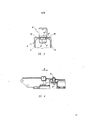
What Fig. 1 represented is a hinge that is used for furniture parts according to of the present invention,
Fig. 2 is the longitudinal section of hinge arms and base plate assembling, expression be the original position of adjusting,
Fig. 3 is identical with Fig. 2, but expression is to adjust hinge arms to be raised to position after the highest order,
Fig. 4 is the top view of base plate,
Fig. 5 is the drawing in side sectional elevation through hold-down screw, is analysing and observe of I in Fig. 2-I line, and
Fig. 6 is the longitudinal sectional view of hinge arms and base plate assembling, and its hold-down screw is amended embodiment.
As shown in Figure 1, a hinge for furniture that is used for furniture parts, it comprises a hinge arms 1, and hinge arms is inserted in two toggles 3, and toggle 3 can link to each other with the dowel bushing 2 of hinge rotationally.The blind hole 8 of a door leaf 8 of dowel bushing 2 insertion furniture parts doors ' in, by the screw (not shown) dowel bushing is fixed on the door leaf 8.With screw (not shown) fixed hinge base plate 4, base plate 4 detachable also adjustable grounds are equipped with hinge arms 1, realize interconnecting of described parts by a hold-down screw 6 on furniture component side plate 7.Press shown in Fig. 2,3 and 6 hinge arms 1 bending, make its cross section form " ∩ " shape, therefore the free end of hinge arms 1 has the depression 13 of an arc, and cross rib is housed under it, and the respective rib 11 on the upper surface of cross rib and the sidewall of the superlative degree 18 of hinge base plate 4 matches.Be close to after the depression 13, can see a left-handed internal thread 15 on the intergrade 17 of base plate 4, hold-down screw 6 is screwed into internal thread 15 hinge arms is fixed on the hinge base plate 4.Consider essential characteristic according to hinge of the present invention, be hinge arms 1 relative base plate 4 its length and highly all be adjustable, form hold-down screw 6 providing below a neck 6 ' ", hold-down screw 6 neck 6 ' " by Fig. 5, thereby form a groove 6 " through low side 6 ' termination.Therefore the skewed surface of groove 6 " being trapezoidal, groove 6 " and base plate 4 intergrades 17 upper shed grooves 10 ' the upper and lower surface of shoulder 10 match, and neck 6 ' " parallel side and this groove 10 ' the vertical plane of shoulder 10 match.
Other at the internal thread 15 that matches with hold-down screw 6, in cross section is the hinge arms 1 of ∩ shape, an internal thread 14 is arranged, an adjustable bolt 5 with cylindrical no threaded end is screwed in the internal thread 14.The cylindrical no threaded end of adjustable bolt 5 has the basal surface 5 of a hemispheric smooth circle ' (or similarly shape), and adjustable bolt 5 is by said basal surface 5 ' the be pressed in smooth part of base plate 4 first order 16.The leading section of hinge arms 1 provides areole in Fig. 1, Fig. 2, Fig. 3 and chain shown in Figure 6 cut with scissors, be used to insert corresponding axle to connect toggle 3, and connect dowel bushings 2 by toggle 3, described part is not just not done more detailed description because they do not embody essence of the present invention at this.
Hinge base plate 4 provides three grades that raise gradually, is realized interconnecting by sidewall 9, and the cross section that makes base plate 4 is a box-shaped body.Wherein, the first order 16 is minimum one-levels, thereby adjusts bolt 5 and hinge arms 1 vertically moving along hinge base plate 4 in the low side restriction that its leading edge has a upright abut can run into adjustable bolt 5.Be higher intergrade 17 after the first order 16, it provide one have groove 10 that opening is arranged '.By shoulder 10 and groove 10 ' adjacency, their surface is partly in general vertical mutually, hold-down screw 6 ' by its trapezoidal groove 6 " that tilt and vertical surface and groove 10 ' match with the surface of shoulder 10, this is one of essential characteristic of the present invention.
In addition, when the assembled furniture parts, thus groove 10 ' import hinge arms 1 at vertical importing hold-down screw 6 of hinge arms, the end portion 6 of hold-down screw 6 ' across groove 10 ' below, thereby when realizing said adjustment measure, hinge arms 1 and hinge base plate are interconnected.At the afterbody of base plate 4, base plate 4 itself is stopped by the described the highest third level 18, and the third level is the high-order bit of base plate 4, at the upper surface of its sidewall cross rib 11 is arranged.In addition, said highest 18 is being openings towards base plate 4 end directions, and its bottom has the hole of the countersunk screw heads of a suitable standard screws, is similar to the hole of opening at the first order 16 front base plates 4 other ends.By last-mentioned countersunk head screw base plate 4 is fixed on the side plate 7 of furniture parts for example.
What Fig. 6 represented is the extremely distortion of hinge for furniture shown in Figure 5 of Fig. 1 according to the present invention.Obviously find out by Fig. 6, the detailed disclosed scheme difference in scheme that this is close and front is the embodiment of hold-down screw 6, hold-down screw 6 has the head of screw of a standard shape in this scheme, and in its end of threaded portion a radial slot that cooperates with corresponding bottle opener is arranged."; by the groove 6 " hold-down screw 6 that at the shaft of hold-down screw 6 a standard shape groove 6 arranged near head of screw and open recess 10 longitudinally ' match, its shoulder 10 of groove 10 ' contact, constitute the lower portion 6 of hold-down screw 6 ' head of screw across said groove 10 ' under.
Hinge for furniture of the present invention can use like this, and hinge arms for example is fixed on furniture parts one door leaf 8 by dowel bushing 2 in advance, hinge arms 1 is installed on the hinge base plate 4 again, and this moment, base plate 4 was fixed on, for example, and on the sidewall 7 of same furniture parts.Arrange that by so the free end section of hinge arms 1 can slide into the front portion of base plate 4, thereby after this hinge arms 1 pushes away hinge arms 1 and the corresponding part of furniture to the A direction shown in Fig. 2 (Fig. 3, Fig. 6) around the sidewall 9 of base plate 4.Thereby, the neck 6 of hold-down screw 6 ' " enter the open recess 10 of base plate 4 intergrades 17 ', be positioned at rib and the engagement of respective rib on the sidewall surfaces of the highest third level 18 under the arc-shaped recess 13 of hinge arms 1 end.After this by with hold-down screw 6(left hand thread screw for example) be screwed in the internal thread 15 of hinge arms 1 and realize that hinge wall 1 is connected with the stable of base plate 4.Therefore in operating process, the lower portion 6 of hold-down screw 6 ' prevention hinge arms 1 is raised from hinge base plate 4.Regulate hinge arms 1 height, regulate gap size between the door leaf of furniture parts and the sidewall thus, by tightening or unscrewing adjustable bolt 5 and finish this operation.Said bolt 5, by its bottom surface 5 ' be pressed on the upper surface of base plate 4 first order 16, the bolt 5 that said adjusting is pressed on the said upper surface is promptly opened height or has been reduced hinge arms 1 to desirable position.In this moving process, the rib 12 that belongs to arc-shaped recess 13 in the hinge arms 1 rolls on the rib 11 that belongs to base plate 4, is similar to gear along the moving of rack rails, and hinge arms 1 can be raise or land on demand.This essential feature according to the inventive subject matter, can obtain the continuous, stable of hinge arms 1 and hinge base plate 4 and enough interconnecting of big rigidity are arranged when regulating the height of hinge arms 1, hinge arms 1 and continuous furniture parts are taken off from built-up member as a door leaf 8 when stoping on the sidewall 7 that hinge arms is connected to furniture parts.As shown in Figure 2, initial rigging position in hinge arms 1, each sidewall of hinge arms 1 be pressed in the bottom of base plate 4 so that two strong points of hinge arms 1 are provided in this position than low edge, bear the screwing force of hold-down screw 6, the cross section of said sidewall forms the side of a ∩, and the result is rigidly connected hinge arms 1 and hinge base plate 4 mutually.
When opening Yishanmen 8 by the power that increases in furniture parts uses, the phenomenon that fluffs that interconnects of hold-down screw 6 and hinge base plate 4 appears sometimes.For fear of under unexpected situation, not allowing hinge arms 1 fall down from base plate 4, in the front portion of base plate 4 first order 16 abut 22 is arranged, it stops the lengthwise movement of hinge arms 1 under described situation, avoid hinge arms to fall down thereby lean against on the said abut 22 by the column part with adjustable bolt 5.
When regulating the height of hinge arms 1 by disclosed Fig. 3, the front portion of hinge arms 1 may be elevated with respect to base plate 4.Because the end section structure of hinge arms 1 as disclosed, said raise on the rib 11 of the upright top edge that belongs to base plate 4 end sections, to roll by the rib 12 that belongs to hinge arms 1 arc end section cause.In the process of being narrated, hinge arms 1 connects together with adjustable bolt 5 and hold-down screw 6, and the relative base plate 4 in their position tilts.Stablize durable interconnective purpose with hinge base plate 4 under the circumstances and at the invention provides hinge arms 1, by the hold-down screw 6 of Fig. 5 have a neck 6 ' "; hold-down screw 6 is by neck 6 ' " by bottom 6 ' termination, thereby forming trapezoidal groove 6 as described before ".The inclined-plane that trapezoidal groove 6 " tilts the hold-down screw that connects together with hinge arms 1; groove 6 " easily and groove 10 ' shoulder 10 corresponding surfaces carry out desirable cooperation, can not produce undesirable subsidiary stress and distortion, make interconnecting of hinge part in the assembling stable and safety, in fact this purpose of the present invention just.In addition, rib 11 is in rib 12 engagements of obliquity continuously reposefully with hinge arms 1, and the stability that hinge arms 1 of the present invention is fixed on the base plate 4 is all higher than the stability of existing this class hinge arrangement scheme from seeing in essence.
By one of claimed embodiment of the present invention as can be known, hinge arms 1 is made of by punching, bending, drawing the 1mm thin plate, and datum width is 15.0mm.After finishing above-mentioned operation, the cross section that makes hinge arms 1 is a ∩ shape, and the rib 12 that comes out just like Fig. 1, Fig. 2, Fig. 3 and hole shown in Figure 6 and compacting.After in respective aperture, processing M7 screw thread (internal thread 14 and 15), then be that hinge arms 1 is handled at last, comprise and remove sharp edge and smooth case surface.
Hinge base plate 4 is formed by die casting by copper-zinc-nickel alloy, thus, obtains apparent fluted and rib 11 from Fig. 2,3,4,5 and 6, after the pressing mold casting, base plate 4 is carried out surfacing, for example use a drum, remove sharp edge and smooth case surface.
Regulate bolt 5 and hold-down screw 6 usefulness steel alloys by Cutting Process, for example make, and also will handle its surface by the lathe automatic device.
Hinge arms 1 is being inserted after suitable axle and toggle 3 interconnected with hinge pin seat 2, and the assembling of hinge just is through with.
Claims (6)
1, a kind of hinge for furniture, comprise a hinge pin seat (2) and hinge arms (1), they interconnect rotationally by means of suspension type toggle (3), detachable and the adjustable ground of hinge arms (1) is installed on the hinge base plate (4), hinge base plate (4) is fixed on furniture parts sidewall paneling (7) or the similar item, at least hinge arms has three places to be connected on base plate (4) or the like parts, it is characterized in that: base plate (4) is provided with a minimum first order (16), have one to stop the upright abut (22) of regulating bolt (5) slip along its leading edge, the described first order (16) back is a higher intergrade (17), be provided with the longitudinal fluting (10) of an opening in intergrade (17) towards the first order (16), groove (10 ') is stopped by the semicircle surface of shoulder (10), groove (10 ') is used for the neck (6 ' " with hold-down screw (6)) match; last; that the back of the intergrade (17) of base plate (4) is the highest third level (18); it is a hollow; opening is towards the tail end of base plate (4); that the sidewall upper surface in highest (18) provides the cross rib (11) that matches with the respective rib (12) of hinge arms (1), three grade (16,17,18) interconnect by sidewall (9) thus, its cross section constitutes the case shape part of hinge base plate (4), its feature also is: the top curved of hinge arms (1) is the part of ∩ shape to form cross section, adjustable bolt (5) is screwed into one first internal thread (14), this adjustable bolt is pressed in the upper surface portion of the first order (16) by its basal surface (5 '), near internal thread (14), hinge arms (1) also has an internal thread (15), hold-down screw (6) is screwed into internal thread (15), at last, the free tail end of hinge arms (1) is provided with an arc-shaped recess (13), below arc-shaped recess (13), from seeing than low side surface located lateral rib (12) is arranged, rib (12) matches with the rib (11) of hinge base plate (4).
2, according to the described hinge for furniture of claim 1, it is characterized in that hinge arms (1) arc-shaped recess (13) is made of circular arc, below arc-shaped recess 13, be provided with prone cross rib (12), the shortest connecting line and rib (12 between center of arc and the base plate (4); 11) engagement place is corresponding.
3, according to the described hinge for furniture of claim 1, it is characterized in that along the surface portion of the shoulder (10) of groove (10 ') it being level and smooth and vertical mutually, they belong to the intergrade (17) of base plate 4.
4, according to claim 1 or 3 described hinge for furniture, (6 ' ") hold-down screw (6) (it is by neck (6 ' ") is stopped by end portion (6 ')) constitutes a trapezoidal groove (6 "); trapezoidal groove skewed surface part cooperates with shoulder (10) upper and lower surface of groove (10 '), and the straight side surface portion of trapezoidal groove partly cooperates with the vertical surface of the shoulder (10) of groove (10 ') to it is characterized in that having neck.
5,, it is characterized in that being provided with the groove (allowable angle of inclination that hinge arms 1 realized with respect to base plate (4) when the chamfered portion of 6 "), its angle of slope were not less than the adjustment hinge of hold-down screw (6) according to the described hinge for furniture of claim 4.
6, according to the hinge for furniture of claim 1, it is characterized in that adjustable bolt (5) basal surface is smooth, hemispheric, or similar shape.
Applications Claiming Priority (2)
| Application Number | Priority Date | Filing Date | Title |
|---|---|---|---|
| YUP-108/91 | 1991-01-23 | ||
| YU10891A YU10891A (en) | 1991-01-23 | 1991-01-23 | FURNITURE HINGE |
Publications (1)
| Publication Number | Publication Date |
|---|---|
| CN1064335A true CN1064335A (en) | 1992-09-09 |
Family
ID=25548369
Family Applications (1)
| Application Number | Title | Priority Date | Filing Date |
|---|---|---|---|
| CN92100971A Pending CN1064335A (en) | 1991-01-23 | 1992-01-23 | Hinge for furniture |
Country Status (10)
| Country | Link |
|---|---|
| US (1) | US5193247A (en) |
| EP (1) | EP0496041A1 (en) |
| JP (1) | JPH0650049A (en) |
| CN (1) | CN1064335A (en) |
| CA (1) | CA2062028A1 (en) |
| CS (1) | CS16492A3 (en) |
| HU (1) | HU209007B (en) |
| MX (1) | MX9200250A (en) |
| PL (1) | PL293270A1 (en) |
| YU (1) | YU10891A (en) |
Cited By (3)
| Publication number | Priority date | Publication date | Assignee | Title |
|---|---|---|---|---|
| CN1307358C (en) * | 2002-06-21 | 2007-03-28 | 黑蒂赫-欧尼有限公司及两合公司 | Hinge |
| CN1788136B (en) * | 2003-05-10 | 2011-10-26 | 埃德沙股份公司 | Assembly aid and method for positioning a hinge in a reproducible manner |
| CN101050682B (en) * | 2006-03-13 | 2013-12-25 | 利伯蒂五金制造公司 | Furniture hinge |
Families Citing this family (5)
| Publication number | Priority date | Publication date | Assignee | Title |
|---|---|---|---|---|
| US5379487A (en) * | 1993-07-19 | 1995-01-10 | Amerock Corporation | Hinge with adjustable hinge arm |
| US5621947A (en) * | 1995-05-11 | 1997-04-22 | Julius Blum Gesellschaft M.G.H. | Hinge for an article of furniture with a frame |
| AT409288B (en) * | 2000-02-28 | 2002-07-25 | Blum Gmbh Julius | FURNITURE HINGE |
| US8307502B2 (en) * | 2009-10-20 | 2012-11-13 | Sub-Zero, Inc. | Integrated hinge assembly |
| CN109415919B (en) * | 2016-07-14 | 2020-04-17 | 世嘉智尼工业株式会社 | Hinge device |
Family Cites Families (9)
| Publication number | Priority date | Publication date | Assignee | Title |
|---|---|---|---|---|
| DE2057261C3 (en) * | 1970-11-21 | 1978-05-24 | Karl Lautenschlaeger Kg Moebelbeschlagfabrik, 6101 Reinheim | Hinge for furniture doors |
| DE2046757C2 (en) * | 1970-09-23 | 1983-09-29 | Karl Lautenschläger KG, Möbelbeschlagfabrik, 6107 Reinheim | Plastic mounting plate for furniture fittings - has thin walled hollow rear anchoring studs radially expanded and axially compressed by driven in plug (AT 15.3.75) |
| AT347813B (en) * | 1974-01-09 | 1979-01-10 | Blum Gmbh | HEIGHT AND DEPTH ADJUSTABLE HINGE WITH A BASE PLATE THAT CAN BE FIXED TO A FURNITURE SIDE PANEL, FOR EXAMPLE |
| AT372482B (en) * | 1974-11-19 | 1983-10-10 | Grass Alfred Metallwaren | FURNITURE HINGE WITH A SIDE AND HEIGHT ADJUSTMENT DEVICE FOR A DOOR LEAF WITH A BASE PLATE COMBINABLE WITH THE DOOR FRAME |
| IT1135541B (en) * | 1980-02-26 | 1986-08-27 | Blum Gmbh Julius | HEIGHT ADJUSTABLE HINGE |
| DE3245227C2 (en) * | 1982-12-07 | 1986-03-20 | Arturo Salice S.P.A., Novedrate, Como | Hinge arm with mounting plate |
| DE3302312A1 (en) * | 1983-01-25 | 1984-07-26 | Karl Lautenschläger KG, Möbelbeschlagfabrik, 6107 Reinheim | FURNITURE HINGE |
| DE3444994C2 (en) * | 1984-12-10 | 1986-10-23 | Arturo Salice S.P.A., Novedrate, Como | Adjustable hinge arm |
| DE3920141C1 (en) * | 1989-06-20 | 1990-08-16 | Arturo Salice S.P.A., Novedrate, Como, It |
-
1991
- 1991-01-23 YU YU10891A patent/YU10891A/en unknown
- 1991-10-15 EP EP91117575A patent/EP0496041A1/en not_active Ceased
- 1991-10-24 US US07/782,306 patent/US5193247A/en not_active Expired - Fee Related
-
1992
- 1992-01-20 CS CS92164A patent/CS16492A3/en unknown
- 1992-01-20 HU HU9200179A patent/HU209007B/en not_active IP Right Cessation
- 1992-01-21 CA CA002062028A patent/CA2062028A1/en not_active Abandoned
- 1992-01-21 MX MX9200250A patent/MX9200250A/en unknown
- 1992-01-23 PL PL29327092A patent/PL293270A1/en unknown
- 1992-01-23 JP JP4010032A patent/JPH0650049A/en active Pending
- 1992-01-23 CN CN92100971A patent/CN1064335A/en active Pending
Cited By (3)
| Publication number | Priority date | Publication date | Assignee | Title |
|---|---|---|---|---|
| CN1307358C (en) * | 2002-06-21 | 2007-03-28 | 黑蒂赫-欧尼有限公司及两合公司 | Hinge |
| CN1788136B (en) * | 2003-05-10 | 2011-10-26 | 埃德沙股份公司 | Assembly aid and method for positioning a hinge in a reproducible manner |
| CN101050682B (en) * | 2006-03-13 | 2013-12-25 | 利伯蒂五金制造公司 | Furniture hinge |
Also Published As
| Publication number | Publication date |
|---|---|
| YU10891A (en) | 1994-06-10 |
| JPH0650049A (en) | 1994-02-22 |
| PL293270A1 (en) | 1992-10-05 |
| HU209007B (en) | 1994-02-28 |
| MX9200250A (en) | 1992-11-01 |
| HUT62365A (en) | 1993-04-28 |
| EP0496041A1 (en) | 1992-07-29 |
| HU9200179D0 (en) | 1992-08-28 |
| CA2062028A1 (en) | 1992-07-24 |
| CS16492A3 (en) | 1992-09-16 |
| US5193247A (en) | 1993-03-16 |
Similar Documents
| Publication | Publication Date | Title |
|---|---|---|
| CN1064335A (en) | Hinge for furniture | |
| DE10040081A1 (en) | Chain link, especially a curved conveyor chain | |
| EP3924661B1 (en) | Balancing arm with friction hinge | |
| DE102007029557C5 (en) | Guide device for a sliding sash | |
| EP0428637B1 (en) | Adjustable holder for the fine adjustment of a dial gauge | |
| EP2882918A1 (en) | Hinge arrangement for doors, windows and the like | |
| EP1342874B1 (en) | Furniture hinge with adjusting device | |
| EP0893564B1 (en) | Pivot bearing for windows or doors | |
| EP1126115B1 (en) | Hinge with self-locking eccentric adjustment drive | |
| CN1214099A (en) | Anchorage mouting for facade panels | |
| US4700875A (en) | Roller entry guide | |
| EP3029240A1 (en) | Corner fitting with variably adjustable clamping range | |
| CN211714860U (en) | Three-dimensional adjustable hinge | |
| EP0143523A1 (en) | Roller entry guide | |
| CN201068698Y (en) | Novel hinge | |
| WO1999046465A1 (en) | Screw-hook hinge adjustable in height | |
| GB2227521A (en) | Adjustable hinges | |
| BE1016414A3 (en) | Hinge, includes two wedge shaped plates for continuously adjusting its position relative to wing or fixed frame | |
| CN111677982A (en) | Involute beating plate for assembling transformer | |
| CN2772656Y (en) | Angle steel inlet guider | |
| CN211714854U (en) | Hinge convenient to adjust installation crack | |
| CN218815866U (en) | Hinge with adjustable distance | |
| EP0942136B1 (en) | Height adjustable hinge pin support | |
| CN2204652Y (en) | Swinging head with single pull rod, four shafts, four-bar linkage | |
| US4134180A (en) | Hinge for door leaves which lie flush, particularly a furniture hinge |
Legal Events
| Date | Code | Title | Description |
|---|---|---|---|
| C06 | Publication | ||
| PB01 | Publication | ||
| C01 | Deemed withdrawal of patent application (patent law 1993) | ||
| WD01 | Invention patent application deemed withdrawn after publication |