CN106332340B - Electromagnetic heating device and heating method thereof - Google Patents
Electromagnetic heating device and heating method thereof Download PDFInfo
- Publication number
- CN106332340B CN106332340B CN201510385966.6A CN201510385966A CN106332340B CN 106332340 B CN106332340 B CN 106332340B CN 201510385966 A CN201510385966 A CN 201510385966A CN 106332340 B CN106332340 B CN 106332340B
- Authority
- CN
- China
- Prior art keywords
- unit
- power
- microprocessor
- energy storage
- electromagnetic
- Prior art date
- Legal status (The legal status is an assumption and is not a legal conclusion. Google has not performed a legal analysis and makes no representation as to the accuracy of the status listed.)
- Active
Links
Images


Classifications
-
- Y—GENERAL TAGGING OF NEW TECHNOLOGICAL DEVELOPMENTS; GENERAL TAGGING OF CROSS-SECTIONAL TECHNOLOGIES SPANNING OVER SEVERAL SECTIONS OF THE IPC; TECHNICAL SUBJECTS COVERED BY FORMER USPC CROSS-REFERENCE ART COLLECTIONS [XRACs] AND DIGESTS
- Y02—TECHNOLOGIES OR APPLICATIONS FOR MITIGATION OR ADAPTATION AGAINST CLIMATE CHANGE
- Y02B—CLIMATE CHANGE MITIGATION TECHNOLOGIES RELATED TO BUILDINGS, e.g. HOUSING, HOUSE APPLIANCES OR RELATED END-USER APPLICATIONS
- Y02B40/00—Technologies aiming at improving the efficiency of home appliances, e.g. induction cooking or efficient technologies for refrigerators, freezers or dish washers
Abstract
The invention relates to the field of electromagnetism, in particular to an electromagnetic heating device. The electromagnetic heating device comprises an electromagnetic conversion module and a heating module; the electromagnetic conversion module comprises a drive conversion unit, a microprocessor, an energy storage unit and a load coil, wherein the load coil is used for being connected with a power supply through the drive conversion unit, and the microprocessor is connected with the energy storage unit and the drive conversion unit; the microprocessor is used for receiving a signal of starting work of the electromagnetic conversion module, controlling the energy storage unit to release electric energy to the load coil when the electromagnetic conversion module is started to work, and controlling the power supply to supply power to the load coil. In addition, the invention also provides a heating method of the electromagnetic heating device.
Description
Technical Field
The invention relates to the field of electromagnetism, in particular to an electromagnetic heating device and a heating method thereof.
Background
Energy problems and environmental problems have been a major issue of social concern. With the development of science and technology and the improvement of the living standard of urban residents, the demand of clean energy is increasingly urgent. However, the combustion of the existing gas water heater can discharge a large amount of carbon dioxide, and a plurality of safety hazards exist.
Common electric water heaters include a water storage type water heater and a common electric water heater, and the water storage type water heater has large volume and low heating efficiency. The common electric water heater usually heats water through a resistance wire, and because the water heating needs a certain time, a certain amount of cold water inevitably flows out at the moment of opening the water faucet, a user generally uses water after the water temperature rises, and the phenomenon is particularly serious in a region with cold climate. The outflow of cold water not only brings inconvenience to users, but also causes a great waste of water resources.
Disclosure of Invention
In view of this, the present invention provides an electromagnetic heating apparatus and a heating method thereof, which are beneficial to avoiding water resource waste and capable of realizing rapid heating.
The electromagnetic heating device provided by the invention comprises an electromagnetic conversion module and a heating module; the electromagnetic conversion module comprises a drive conversion unit, a microprocessor, an energy storage unit and a load coil, wherein the load coil is used for being connected with a power supply through the drive conversion unit, and the microprocessor is connected with the energy storage unit and the drive conversion unit; the microprocessor is used for receiving a signal of starting work of the electromagnetic conversion module, controlling the energy storage unit to release electric energy to the load coil when the electromagnetic conversion module is started to work, and controlling the power supply to supply power to the load coil.
In the electromagnetic heating device provided by the invention, the microprocessor controls the energy storage unit to release electric energy to the load coil and controls the power supply to supply power to the load coil within a preset time period when receiving a signal for starting the electromagnetic heating device; after the preset time period, the microprocessor controls the power supply to continuously supply power to the load coil and stops the energy storage unit from releasing electric energy for the load coil.
The electromagnetic conversion module also comprises a voltage adjusting unit and an input sampling unit, the drive conversion unit comprises a rectifying and filtering unit and a power drive conversion unit, the input sampling unit is connected with the rectifying and filtering unit and the voltage adjusting unit, and the voltage adjusting unit is also connected with the energy storage unit, the microprocessor and the power drive conversion unit; the input sampling unit collects a first voltage of the power source after being processed by the rectifying and filtering unit in real time and sends the first voltage to the voltage adjusting unit, the voltage adjusting unit adjusts a second voltage of the energy storage unit after being processed by the voltage adjusting unit in real time, the second voltage is equal to the first voltage, the phases of the second voltage and the first voltage are the same, and when the electromagnetic heating device is started to work, the first voltage and the second voltage supply power to the power driving conversion unit at the same time.
In the electromagnetic heating device provided by the invention, the electromagnetic conversion module further comprises a charging management unit, the charging management unit is respectively connected with the rectifying and filtering unit, the energy storage unit and the microprocessor, and the microprocessor controls the charging management unit to adjust the charging current and the charging time of the power supply for charging the energy storage unit in real time after the electromagnetic conversion module is closed.
In the electromagnetic heating device provided by the invention, the energy storage unit has a charging threshold voltage, the microprocessor controls the power supply to charge the energy storage unit when the electromagnetic conversion module is closed and the voltage at two ends of the energy storage unit is smaller than the charging threshold voltage, and the microprocessor controls the power supply to stop charging the energy storage unit when the voltage at two ends of the energy storage unit is equal to the charging threshold value.
In the electromagnetic heating device provided by the invention, the power driving conversion unit further comprises a power conversion unit and a power driving unit, the power driving unit is connected with the microprocessor, the power conversion unit is respectively connected with the rectifying and filtering unit and the power driving unit, the microprocessor outputs a variable frequency signal to the power driving unit, and controls the output power of the power driving unit and the power conversion unit so as to adjust the output power of the load coil.
In the electromagnetic heating device provided by the invention, the electromagnetic conversion module further comprises a one-way conduction unit, which comprises a first input end, a second input end and an output end, wherein the first input end is connected with the output end of the rectification filter unit, the second input end is connected with the output end of the voltage regulation unit, and the output end is connected to the power conversion unit.
In the electromagnetic heating device provided by the invention, the electromagnetic conversion module further comprises a water switch and a temperature sampling unit which are respectively connected with the microprocessor, the heating module comprises a magnetic conduction unit and a water flow channel, the water switch is positioned at the water flow channel, the temperature sampling unit is used for collecting a first temperature value of water flow in the water flow channel and sending the first temperature value to the microprocessor, the microprocessor is also used for storing a preset second temperature value, receiving the first temperature value and controlling the output power of the drive conversion unit according to the difference value of the first temperature value and the second temperature value.
In the electromagnetic heating device provided by the invention, the electromagnetic conversion module further comprises a display unit and a touch unit, the display unit and the touch unit are respectively connected to the microprocessor, the display unit displays the temperature of water flow and the opening time of the water flow in real time, and the touch unit is used for receiving a signal for opening or closing the power supply by a user and a preset or stored signal for the temperature of the water flow; the electromagnetic conversion module further comprises a first capacitor, wherein the first end of the first capacitor is connected with the output end of the drive conversion unit, and the second end of the first capacitor is connected with the load coil.
The invention also discloses a heating method of the electromagnetic heating device, which at least comprises the following steps:
it at least comprises the following steps: receiving a signal of starting the electromagnetic heating device; controlling the energy storage unit to release electric energy to the load coil, and simultaneously controlling the power supply to supply power to the load coil; the load coil generates an alternating magnetic field and excites the heating module to generate eddy current, and the eddy current enables water flow to generate heat through heat transfer.
In the electromagnetic heating device provided by the invention, because the energy storage unit is arranged, at the beginning of the starting operation of the electromagnetic conversion module, the microprocessor controls the energy storage unit to release electric energy to the load coil and controls the power supply to supply power to the load coil, so that the output power is increased, the alternating magnetic field generated by the load coil is increased, the eddy current heating effect of the magnetic conduction unit in the heating module is enhanced, the water flow can be rapidly heated at the moment of starting the electromagnetic heating device, and the waste of water resources is reduced when the electromagnetic heating device is started. The invention solves the problem that the resident electric water heater in the prior art can not increase the power capacity without limit so as to achieve the purpose of quick heating from another aspect.
Drawings
The invention will be further described with reference to the accompanying drawings and examples, in which:
fig. 1 is a schematic structural diagram of an electromagnetic heating apparatus 100 according to a preferred embodiment of the present invention;
fig. 2 is a schematic structural diagram of the electromagnetic conversion module 110 according to a preferred embodiment of the present invention;
fig. 3 is a schematic structural diagram of a rectifying and filtering unit 1110 according to a preferred embodiment of the present invention;
fig. 4 is a schematic circuit diagram of the power conversion unit 1111a provided in the present invention;
fig. 5 is a schematic structural diagram of an electromagnetic conversion module 110 according to another preferred embodiment of the present invention;
FIG. 6 is a schematic diagram of a unidirectional conducting unit 10;
FIG. 7 is a schematic diagram of the connection of the first capacitor;
FIG. 8 is a schematic flow chart illustrating a heating method of an electromagnetic heating apparatus according to a preferred embodiment of the present invention;
fig. 9 is a schematic view of the working process of the electromagnetic heating device provided by the invention when the water flow is closed.
Detailed Description
In order to explain the electromagnetic heating device provided by the invention, the following detailed description is made in combination with the attached drawings and the written description.
In the description of the present invention, it is to be noted that, unless explicitly stated or limited otherwise, the terms "connected" or "connected" are to be construed broadly and may refer to electrical communication between two elements; they may be directly connected or indirectly connected through an intermediate, and those skilled in the art will understand the specific meanings of the above terms according to specific situations. Furthermore, the terms "first", "second" and "first" are used for descriptive purposes only and are not to be construed as indicating or implying relative importance or implicitly indicating the number of technical features indicated. Thus, a feature defined as "first" or "second" may explicitly or implicitly include one or more of that feature.
The working principle of the electromagnetic heating device provided by the invention is as follows: the alternating current passes through the load coil to generate a magnetic field, the magnetic lines of force pass through the magnetizer and generate an eddy current in the magnetizer, and the eddy current generates heat to raise the temperature of water flowing through the magnetizer through heat transfer, so that the heating purpose is achieved. At the moment that the water flow is started, the electromagnetic heating device is powered by the power supply for the load coil, and meanwhile, the energy storage unit releases stored energy to the discharging load coil, so that the starting power of the load coil is greatly increased, the water flow is rapidly heated, and the purpose of instant heating is achieved.
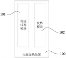
As shown in fig. 1, which is a schematic structural diagram of an electromagnetic heating apparatus 100 according to a preferred embodiment of the present invention, the electromagnetic heating apparatus 100 includes an electromagnetic conversion module 110 and a heat generating module 120, and the electromagnetic conversion module 110 and the heat generating module 120 are insulated from each other by an insulator (not shown in the figure). The heat generation module 120 generates eddy current and generates heat when the electromagnetic conversion module 120 operates.
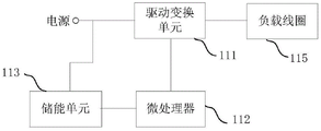
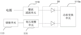
Fig. 2 is a schematic structural diagram of the electromagnetic conversion module 110 according to a preferred embodiment of the invention. The electromagnetic conversion module 110 includes a driving conversion unit 111, a microprocessor 112, an energy storage unit 113 and a load coil 115, wherein the load coil 115 is used for being connected with a power supply through the driving conversion unit 111, and the microprocessor 112 is further connected with the energy storage unit 113 and the driving conversion unit 111. The microprocessor 112 is configured to receive a signal that the electromagnetic conversion module 110 starts to operate, and control the energy storage unit 113 to release electric energy to the load coil 115 when the electromagnetic conversion module 110 starts to operate (for example, when water flow is turned on), and control the power supply to supply power to the load coil 115. In this embodiment, the energy of the energy storage unit 113 is obtained by controlling the power supply to charge the power supply by the microprocessor 112 when the electromagnetic conversion module 110 is not in operation.
In a preferred embodiment, the microprocessor 112 controls the energy storage unit 113 to release electric energy to the load coil 115 and controls the power supply to supply power to the load coil 115 during a predetermined time period when receiving a signal that the electromagnetic conversion module 100 is turned on; after the predetermined period of time, the microprocessor 112 controls the power supply to continue supplying power to the load coil 115, and stops the energy storage unit 113 from releasing power to the load coil 115. The predetermined time period is timed from when the signal occurs. The time length of the predetermined time period can be set according to actual conditions and the energy storage capacity of the energy storage unit, for example, 0-120 seconds.
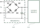
The driving conversion unit 111 is used for controlling and outputting high-frequency power according to an instruction of the microprocessor 112, and driving the load coil 115 to work. Specifically, the driving conversion unit 111 includes a rectifying and filtering unit 1110 and a power driving conversion unit 1111, the rectifying and filtering unit 1110 is used for converting the power supply into a direct current, and the power supply can provide an alternating voltage of 220V or 110V. The power driving conversion unit 1111 is configured to convert the direct current output by the rectifying and filtering unit 1110 into a high-frequency alternating current according to an instruction of the microprocessor 112 and output the high-frequency alternating current. Specifically, the power driving converting unit 1110 includes a power converting unit 1111a and a power driving unit 1111b, the power driving unit 1111b is connected to the microprocessor 112, the power converting unit 1111a is respectively connected to the rectifying and filtering unit 1110 and the power driving unit 1111b, the microprocessor 112 outputs a frequency-converted signal to the power driving unit 1111b, and controls output power of the power driving unit 1111b and the power converting unit 1111a to adjust output power of the load coil 115.
As shown in fig. 3, which is a schematic structural diagram of the rectifying-filtering unit 1110 according to a preferred embodiment of the present invention, it at least includes a single-phase bridge rectifier circuit composed of diodes D1, D2, D3 and D4 and a filtering capacitor C, where the single-phase bridge rectifier circuit functions to convert ac (power) into dc, and the filtering capacitor C functions to filter ac noise. The rectifying and filtering unit can also be replaced by other circuit diagrams.
The power driving unit 1110b may be implemented by MOS transistor or triode, and its driving signal is implemented by PWM or frequency conversion, for example, UC3846 type. The power conversion unit 1111a may employ a full-bridge high-frequency inverter circuit (IGBT or MOSFET), such as that shown in fig. 4, which is a schematic circuit diagram of the power conversion unit 1111a according to a preferred embodiment of the present invention. The full-bridge high-frequency inverter circuit comprises 4 switching tubes IGBT1, IGBT2, IGBT3 and IGBT4, and the full-bridge high-frequency inverter circuit is driven by the power driving unit 1110b to convert direct current output by the rectifying and filtering unit 1110 into high frequency. In other embodiments, the power conversion unit may also employ a half-bridge high-frequency inverter circuit (IGBT or MOSFET).
The microprocessor 112 is a central processing unit of the electromagnetic conversion module 110, and is configured to process various signals and control corresponding functional units to operate. The microprocessor 112 is connected to the power supply, for example, via a control switch (not shown), and controls the power supply to be turned on or off. The control switch may be an ac contactor. The microprocessor 112 may be a 4-bit, 8-bit, or 16-bit higher-level single chip microcomputer.
The energy storage unit 113 is configured to release electric energy for the load coil 115 according to a control instruction of the microprocessor 112. The energy storage unit 113 may be a lithium ion battery, a super capacitor (farad capacitor), a storage battery, or the like. The energy storage unit 113 has a charging threshold voltage, when the microprocessor 112 stops the operation of the electromagnetic conversion module (for example, when water flow is closed), and the voltage across the energy storage unit 113 is smaller than the charging threshold voltage, the microprocessor 112 controls the power supply to charge the energy storage unit 113, and when the voltage across the energy storage unit 113 reaches the charging threshold voltage, the microprocessor 112 controls the power supply to stop charging the energy storage unit. That is, after the water flow is closed, the power supply charges the energy storage unit 113, so that the energy storage unit 113 has enough energy to release when the water flow is opened next time.
In general, since the power supply capacity of a common resident is about 60A and 220V, that is, about 12kw, and the remaining available capacity is about 6kw except other household appliances such as an air conditioner 2, an induction cooker, etc., by the energy storage design of the present invention, that is, the main line power supply is 6kw, if the energy storage is 6kw, 12kw of power can be released within a predetermined time period without generating the electricity safety problem due to overload of the power used by the resident. Meanwhile, when the electromagnetic conversion module is started, the heating module can achieve instant heating due to double power provided in a short time, namely, water can be rapidly heated at the moment when the electromagnetic heating device is started, and therefore the problem that the power supply capacity of the existing residents cannot be increased without limit is solved.
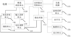
The electromagnetic conversion module 110 further includes an input sampling unit 116 and a voltage adjusting unit 117, the input sampling unit 116 is connected to the rectifying and filtering unit 1110 and the voltage adjusting unit 117, and the voltage adjusting unit 117 is further connected to the energy storage unit 11, the microprocessor 112 and the power conversion unit 1111. The input sampling unit 116 collects a first voltage of the power source processed by the rectifying and filtering unit 1110 in real time and sends the first voltage to the voltage adjusting unit 117, the energy storage unit 113 outputs a second voltage through the voltage adjusting unit 117, the voltage adjusting unit 117 adjusts the second voltage in real time to enable the second voltage to be equal to the first voltage, the phases of the second voltage and the first voltage are the same, and the first voltage and the second voltage simultaneously supply power to the power driving conversion unit 1111 when the electromagnetic conversion module 110 is started to operate. At this time, the voltage output by the energy storage unit 113 is equal to the voltage output by the power supply, that is, two equal voltages simultaneously supply power to the load coil 115, that is, the power output by the energy storage unit may be equal to the power output by the power supply, or may not be equal to the power output by the power supply.
Fig. 5 is a schematic structural diagram of an electromagnetic conversion module 110 according to a preferred embodiment of the invention. The electromagnetic conversion module 120 further includes a charging and discharging management unit 118, the charging and discharging management unit 118 is respectively connected to the rectifying and filtering unit 1110, the energy storage unit 113 and the microprocessor 112, and the charging management unit 118 adjusts the charging current and the charging time for the energy storage unit 113 to be charged by the power supply in real time after the electromagnetic conversion module 110 is turned off.
The electromagnetic conversion module 120 further includes a water switch 114 and a temperature sampling unit 119 connected to the microprocessor 112, the heating module 102 includes a magnetic conduction unit and a water flow channel, the water switch 114 is located at the water flow channel, the water switch 114 is used for detecting a first temperature value of the water flow channel, the temperature sampling unit 119 collects the first temperature value and a second temperature value preset or stored by a user, and sends the first temperature value and the second temperature value to the microprocessor 112, and the microprocessor 112 controls the output power of the driving conversion unit 111 according to a difference value between the first temperature value and the second temperature value.
The electromagnetic conversion module 120 further includes a display unit 12a and a touch unit 12b, the display unit 12a and the touch unit 12b are respectively connected to the microprocessor 112, the display unit 12a displays the temperature of the water flow and the time of turning on the water flow in real time, and the touch unit 12b is configured to receive a signal for turning on or off the power supply and a setting signal for the temperature of the water flow from a user, and transmit the signal to the microprocessor 112.
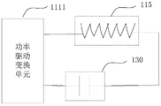
Fig. 6 is a schematic structural diagram of a unidirectional conducting unit 10. The electromagnetic conversion module 120 further includes the unidirectional conducting unit 10, which includes a first input terminal, a second input terminal, and an output terminal, wherein the first input terminal is connected to the output terminal of the rectifying and filtering unit 1110, the second input terminal is connected to the output terminal of the voltage adjusting unit 117, and the output terminal is connected to the power converting unit 1111 a. Preferably, the unidirectional conducting unit 10 comprises two diodes connected in parallel. The single-phase conduction function of the single-phase conduction unit 10 of this embodiment is used to ensure that the first voltage output by the rectifying and filtering unit 1110 is equal to the second voltage output by the voltage adjusting unit, that is, two equal voltages are connected in parallel to supply power to the function transforming unit, so as to prevent the energy of the energy storing unit or the power supply from being unable to be released to the power transforming unit when the first voltage is not equal to the second voltage.
Preferably, the electromagnetic conversion module further includes a first capacitor 130, as shown in fig. 7, which is a schematic diagram illustrating the connection of the first capacitor 130. A first end of the first capacitor 130 is connected to the output end of the driving transformation unit 111, and a second end of the first capacitor 130 is connected to the load coil 115.
The heating module 120 includes a magnetic conductive unit and a water flow channel (not shown), and the water switch is located at the water flow channel; preferably, the water switch is positioned at the water inlet. The water flow channel comprises a water inlet and a water outlet, the magnetic conduction unit at least comprises a magnetizer, and the water flow channel is positioned in the magnetizer. The magnetizer generates vortex and then heats water flow in the water flow channel through heat conduction.
Fig. 8 is a schematic flow chart of a heating method of an electromagnetic heating apparatus according to a preferred embodiment of the invention. The heating method at least comprises the following steps:
step S01: and receiving a signal of starting the work of the electromagnetic conversion module.
The signal of the electromagnetic conversion module for starting comprises a signal of water flow starting, and the microprocessor receives the signal.
Step S02: the method comprises the following two steps of:
step S021: the microprocessor controls the power supply to output power for the load coil, specifically, the microprocessor switches on the power supply and the driving power conversion unit and controls the power of the power supply to be transmitted to the driving power conversion unit;
step S022: and the microprocessor opens the energy storage unit and controls the energy storage unit to release electric energy to the load coil. Specifically, in an embodiment, before the power of the energy storage unit is transferred to the driving power conversion unit, the microprocessor turns on the voltage adjustment unit, and the second voltage is equal to the first voltage through the input voltage sampling unit.
And the microprocessor in the steps S021 and S022 controls the power supply and the energy storage unit to output the power supply and the energy storage unit to the driving power conversion unit at the same time, and the driving power conversion unit supplies power to the load coil.
Step S03: the load coil generates an alternating magnetic field and excites the heating module to generate eddy current, and the eddy current enables water flow to generate heat through heat transfer.
Step S04: after a preset time period, the microprocessor controls the power supply to continuously supply power to the load coil and stops the energy storage unit from releasing electric energy for the load coil until the electromagnetic heating device finishes working.
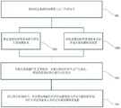
As shown in fig. 8, it is a schematic view of a working flow of the electromagnetic heating apparatus provided by the present invention when the electromagnetic heating apparatus stops working, and the working flow at least includes the following steps:
step S11: and receiving a signal that the electromagnetic conversion module stops working.
Step S12: judging whether the voltage of the energy storage unit is smaller than the charging threshold voltage of the energy storage unit, if so, performing step S13; otherwise, the process goes to step S15.
Step S13: and the microprocessor closes the drive conversion unit and controls the power supply to charge the energy storage unit. And when the driving conversion unit stops working, the load coil stops emitting the magnetic field.
Step S14: judging whether the voltage of the energy storage unit reaches the charging threshold voltage, and if so, carrying out the next step; if not, return to step S13.
Step S15: and the microprocessor controls the power supply to be turned off and stops the power supply from charging the energy storage unit.
In the electromagnetic heating device and the heating method thereof provided by the invention, because the energy storage unit is arranged, at the moment when the electromagnetic conversion module is started to work, the microprocessor controls the energy storage unit to release electric energy to the load coil and controls the power supply to supply power to the load coil, so that the output power is increased on the premise of not increasing the supply capacity of the main power supply, the magnetic field generated by the load coil is increased, the heating module achieves quick heating, the water can be rapidly heated at the moment when the electromagnetic heating device is started, and the waste of water resources when the electromagnetic heating device is started is reduced.
The above-mentioned preferred embodiments of the electromagnetic heating device and the heating method thereof provided by the present invention should not be construed as limiting the scope of the claims of the present invention, and those skilled in the art should understand that many modifications and substitutions can be made without departing from the spirit of the present invention, and all such modifications and substitutions should be considered to be within the scope of the claims of the present invention, i.e., the scope of the claims of the present invention shall be subject to the claims.
Claims (9)
1. An electromagnetic heating device comprises an electromagnetic conversion module and a heating module;
the electromagnetic conversion module comprises a drive conversion unit, a microprocessor, an energy storage unit and a load coil, wherein the load coil is used for being connected with a power supply through the drive conversion unit, and the microprocessor is connected with the energy storage unit and the drive conversion unit; the microprocessor is used for receiving a signal of starting work of the electromagnetic conversion module, controlling the energy storage unit to release electric energy to the load coil when the electromagnetic conversion module is started to work within a preset time period of starting the signal, and controlling the power supply to supply power to the load coil; the driving conversion unit comprises a rectifying and filtering unit and a power driving conversion unit, the power driving conversion unit also comprises a power conversion unit and a power driving unit, the power driving unit is connected with the microprocessor, the power conversion unit is respectively connected with the rectifying and filtering unit and the power driving unit, the microprocessor outputs a frequency conversion signal to the power driving unit, and controls the output power of the power driving unit and the power conversion unit so as to adjust the output power of the load coil.
2. The electromagnetic heating apparatus according to claim 1, wherein: and the microprocessor is also used for controlling the power supply to continuously supply power to the load coil and stopping the energy storage unit from releasing electric energy for the load coil after the preset time period.
3. The electromagnetic heating apparatus according to claim 1, characterized in that: the electromagnetic conversion module further comprises a voltage adjusting unit and an input sampling unit, the input sampling unit is connected with the rectifying and filtering unit and the voltage adjusting unit, and the voltage adjusting unit is further connected with the energy storage unit, the microprocessor and the power driving and converting unit; the input sampling unit collects a first voltage processed by the power supply through the rectifying and filtering unit in real time and sends the first voltage to the voltage adjusting unit, the voltage adjusting unit adjusts a second voltage output by the energy storage unit through the voltage adjusting unit in real time, the second voltage is equal to the first voltage, the phase of the second voltage is the same, and when the electromagnetic conversion module is started to work, the first voltage and the second voltage supply power to the power driving conversion unit at the same time.
4. An electromagnetic heating apparatus according to claim 3, characterized in that: the electromagnetic conversion module further comprises a charging management unit, the charging management unit is respectively connected with the rectifying and filtering unit, the energy storage unit and the microprocessor, and the microprocessor controls the charging management unit to adjust the charging current and the charging time of the power supply for charging the energy storage unit in real time after the electromagnetic conversion module is closed.
5. The electromagnetic heating apparatus according to claim 1, characterized in that: the energy storage unit is provided with a charging threshold voltage, the microprocessor controls the power supply to charge the energy storage unit when the electromagnetic conversion module is closed and the voltages at the two ends of the energy storage unit are smaller than the charging threshold voltage, and controls the power supply to stop charging the energy storage unit when the voltages at the two ends of the energy storage unit are equal to the charging threshold voltage.
6. An electromagnetic heating apparatus as set forth in claim 3, wherein: the electromagnetic conversion module further comprises a one-way conduction unit which comprises a first input end, a second input end and an output end, wherein the first input end is connected with the output end of the rectification filtering unit, the second input end is connected with the output end of the voltage adjusting unit, and the output end is connected to the power conversion unit.
7. The electromagnetic heating apparatus according to claim 1, wherein: the electromagnetic conversion module still include respectively with water switch and temperature sampling unit that microprocessor connects, the module that generates heat includes magnetic conduction unit and rivers passageway, the water switch is located rivers passageway department, the temperature sampling unit is arranged in gathering rivers passageway rivers's first temperature value, and will first temperature value sends microprocessor, microprocessor still is used for the storage to be used for the second temperature value of predetermineeing and receives first temperature value, and according to the difference of first temperature value and second temperature value, control drive transform unit output.
8. The electromagnetic heating apparatus according to claim 7, wherein: the electromagnetic conversion module further comprises a display unit and a touch unit, the display unit and the touch unit are respectively connected to the microprocessor, the display unit displays the temperature of water flow and the opening time of the water flow in real time, and the touch unit is used for receiving signals of a user for opening and closing the power supply or setting the temperature of the water flow; the electromagnetic conversion module further comprises a first capacitor, wherein the first end of the first capacitor is connected with the output end of the drive conversion unit, and the second end of the first capacitor is connected with the load coil.
9. A heating method of an electromagnetic heating apparatus according to any one of claims 1 to 8, comprising at least the steps of: receiving a signal for starting the electromagnetic conversion module; controlling the energy storage unit to release electric energy to the load coil, and simultaneously controlling the power supply to supply power to the load coil; the load coil generates an alternating magnetic field and excites the heating module to generate eddy current, and the eddy current heats water through heat transfer.
Priority Applications (1)
| Application Number | Priority Date | Filing Date | Title |
|---|---|---|---|
| CN201510385966.6A CN106332340B (en) | 2015-06-30 | 2015-06-30 | Electromagnetic heating device and heating method thereof |
Applications Claiming Priority (1)
| Application Number | Priority Date | Filing Date | Title |
|---|---|---|---|
| CN201510385966.6A CN106332340B (en) | 2015-06-30 | 2015-06-30 | Electromagnetic heating device and heating method thereof |
Publications (2)
| Publication Number | Publication Date |
|---|---|
| CN106332340A CN106332340A (en) | 2017-01-11 |
| CN106332340B true CN106332340B (en) | 2022-08-19 |
Family
ID=57727213
Family Applications (1)
| Application Number | Title | Priority Date | Filing Date |
|---|---|---|---|
| CN201510385966.6A Active CN106332340B (en) | 2015-06-30 | 2015-06-30 | Electromagnetic heating device and heating method thereof |
Country Status (1)
| Country | Link |
|---|---|
| CN (1) | CN106332340B (en) |
Families Citing this family (2)
| Publication number | Priority date | Publication date | Assignee | Title |
|---|---|---|---|---|
| CN109431293A (en) * | 2018-12-07 | 2019-03-08 | 苏州工业职业技术学院 | A kind of liquid heating |
| CN111473647A (en) * | 2020-04-16 | 2020-07-31 | 佛山市南海创利有色金属制品有限公司 | Intelligent control method and intelligent control system for aluminum alloy smelting processing temperature |
Citations (7)
| Publication number | Priority date | Publication date | Assignee | Title |
|---|---|---|---|---|
| CN85104518A (en) * | 1985-06-13 | 1987-02-04 | 三洋电机株式会社 | Induction heating equipment |
| JP2000215971A (en) * | 1999-01-22 | 2000-08-04 | Canon Inc | Induction heating device and image forming device |
| CN101409959A (en) * | 2008-11-14 | 2009-04-15 | 张军才 | Intelligence control circuit for quasi-resonance electromagnet water heater |
| CN101551157A (en) * | 2008-04-02 | 2009-10-07 | 刘金根 | Electromagnetic induction water storage type water heater |
| CN204214553U (en) * | 2014-11-10 | 2015-03-18 | 青岛万力科技有限公司 | A kind of motor wireless monitoring device |
| CN204244499U (en) * | 2014-12-19 | 2015-04-01 | 邢台竹源电子科技有限公司 | Invariable power varible-frequency electromagnetic heater |
| CN204993919U (en) * | 2015-06-30 | 2016-01-20 | 深圳市泰金田科技有限公司 | Electromagnetic heating device |
-
2015
- 2015-06-30 CN CN201510385966.6A patent/CN106332340B/en active Active
Patent Citations (7)
| Publication number | Priority date | Publication date | Assignee | Title |
|---|---|---|---|---|
| CN85104518A (en) * | 1985-06-13 | 1987-02-04 | 三洋电机株式会社 | Induction heating equipment |
| JP2000215971A (en) * | 1999-01-22 | 2000-08-04 | Canon Inc | Induction heating device and image forming device |
| CN101551157A (en) * | 2008-04-02 | 2009-10-07 | 刘金根 | Electromagnetic induction water storage type water heater |
| CN101409959A (en) * | 2008-11-14 | 2009-04-15 | 张军才 | Intelligence control circuit for quasi-resonance electromagnet water heater |
| CN204214553U (en) * | 2014-11-10 | 2015-03-18 | 青岛万力科技有限公司 | A kind of motor wireless monitoring device |
| CN204244499U (en) * | 2014-12-19 | 2015-04-01 | 邢台竹源电子科技有限公司 | Invariable power varible-frequency electromagnetic heater |
| CN204993919U (en) * | 2015-06-30 | 2016-01-20 | 深圳市泰金田科技有限公司 | Electromagnetic heating device |
Also Published As
| Publication number | Publication date |
|---|---|
| CN106332340A (en) | 2017-01-11 |
Similar Documents
| Publication | Publication Date | Title |
|---|---|---|
| US10230298B2 (en) | Resistorless precharging | |
| AU2011323988B2 (en) | System and method for bidirectional DC-AC power conversion | |
| CN101997323B (en) | Charging system with galvanic isolation and multiple operating modes | |
| US9654015B2 (en) | Bidirectional DC/DC converter, and bidirectional power converter | |
| CN106068605B (en) | Power-converting device | |
| CN103269537B (en) | Multi-circuit current-limiting power supplying circuit, controlling method thereof and current-limiting power supplying method thereof | |
| JP2011103761A (en) | Power conversion device | |
| CN102195506A (en) | Systems and methods for deactivating a matrix converter | |
| CN101997324A (en) | Systems and methods for bi-directional energy delivery with galvanic isolation | |
| US20180351374A1 (en) | Battery charge system | |
| CN104167799B (en) | A kind of charge-discharge system, method and photovoltaic generating system | |
| KR101116498B1 (en) | Energy storage system | |
| TW201230601A (en) | Charging apparatus with alternating current- and direct current- charging functions for mobile vehicle | |
| CN104578253B (en) | High-frequency triangular transformation technology-based electric vehicle motor driving DC/DC transformation device | |
| KR101873113B1 (en) | Startup method of semiconductor transformer using subsidiary power and dc/dc converter | |
| CN106332340B (en) | Electromagnetic heating device and heating method thereof | |
| CN107994781A (en) | A kind of converter plant and its control method | |
| CN206865351U (en) | A kind of electric precharging circuit | |
| CN213734669U (en) | Energy conversion device and vehicle | |
| CN204993919U (en) | Electromagnetic heating device | |
| CN204887506U (en) | Electromagnetic heater | |
| CN209282889U (en) | A kind of equalization charging circuit, charging circuit and charging unit | |
| CN112997396B (en) | Adapter device for bidirectional operation | |
| JP2013131305A (en) | Induction heating cooker | |
| CN202973323U (en) | Wind-energy electric heater |
Legal Events
| Date | Code | Title | Description |
|---|---|---|---|
| PB01 | Publication | ||
| PB01 | Publication | ||
| C10 | Entry into substantive examination | ||
| SE01 | Entry into force of request for substantive examination | ||
| GR01 | Patent grant | ||
| GR01 | Patent grant |