CN1062338C - Water supply system - Google Patents
Water supply system Download PDFInfo
- Publication number
- CN1062338C CN1062338C CN 95109699 CN95109699A CN1062338C CN 1062338 C CN1062338 C CN 1062338C CN 95109699 CN95109699 CN 95109699 CN 95109699 A CN95109699 A CN 95109699A CN 1062338 C CN1062338 C CN 1062338C
- Authority
- CN
- China
- Prior art keywords
- inverter
- water
- pump
- frequency
- restarts
- Prior art date
- Legal status (The legal status is an assumption and is not a legal conclusion. Google has not performed a legal analysis and makes no representation as to the accuracy of the status listed.)
- Expired - Lifetime
Links
Images


Abstract
A water supply system comprises plenty of inverter apparatus which comprise respective protectors and have the function of controlling by a pump and speed regulated pumps connected to the inverter apparatus by a rate of 1:1. The pump controller is composed of only two inverter apparatus to formed a perfect double type to improve the dependability of the system. When one of the two inverter apparatus is stopped, the stopped inverter apparatus is again started by the other inverter apparatus of a reoperation command. Thus, when a reoperation command is given to the inverter apparatus and the cause of protection for the inverter device is cancelled, the stopped inverter apparatus will be again started so that the possibility of stopping completely the inverter apparatus can be reduced.
Description
The present invention relates to a kind of water system; this system has pump control function and comprises the variable speed pump that is driven by the inverter with protective gear of protecting himself; more particularly, relate to a kind of even since each inverter of protective gear of himself in a water supply installation that quits work and also can continue to supply water.
Prior art is designed to utilize the water system of variable speed pump, therefore control circuit with microcomputer wherein is housed, so that order the operation of each inverter to provide separately, under the situation that the requirement of water changes, often there is order will issue each inverter, therefore the operating rate of the motor of driven pump changes, concerns (for example, constant pressure of supply water or constant user side hydraulic pressure) and continuous water supply with the constant pressure of the water supply side that remains on pump.The example of this type system for example is disclosed in, JP-B-6-52079 and JP-B-6-52080.
The inverter that is used for such water system has and is installed in wherein each kind of protective circuit, is used to protect himself.The details of the protective system of this inverter for example is described in, and JP-A-57-6576, JP-A-58-224575 are among JP-A-59-185170, JP-A-60-84972 and the JP-A-61-224876.
In this method, because having, the inverter of water system is installed in wherein in order to protect the various protective circuits of its inverter, (such as moment power failure, excess load, temperature rising, noise etc.) can make inverter quit work because a variety of causes.In addition, the time-out during inverter quits work supplies water and relates to great problem.For fear of this situation, in this case, a kind of motor that is used for driven pump from its inverter working mode change to the specified of it or based on the fixed speed mode of operation of civil power, prevents to supply water and suspends usually.
Yet in the water system of above-mentioned this prior art, this is impossible, suspends for avoiding supplying water, as long as control circuit is not the double system type, the microcomputer of wherein packing into will become shortcoming to control circuit.
In addition, when inverter for a certain reason is stopped work and specified or when working on based on pump civil power, fixed speed work, this causes that pressure of supply water will respond the variation of the amount of water required and changes.Have again, even because pump also drives at its full speed degree under light load, so pump the cost of operate power become undesirably high.
The water system of prior art also has a problem to be, under the out-of-work situation of inverter, require to find its out-of-work reason rapidly and restart this inverter, but can undesirably cause so a kind of situation, in a single day promptly send a warning from inverter, this inverter that the surfaceman must receive an emergency call and defendant needs to repair.
Therefore, an object of the present invention is to provide a kind of improved water system, this system can avoid or reduce the state that quits work of the inverter of being packed into fully and can keep supplying water continuously.
According to one aspect of the present invention, this purpose is by providing a kind of water system to reach, this water system comprises: the sensor input device is used to import the water supply information signal from pressure transducer on the water outlet that is installed in water distribution pipe and flow transducer; A plurality of DC-to-AC converters with protective gear are used to protect itself, produce the AC power of variable frequency according to a kind of drive scheme of pre-programmed; A plurality of motors that are connected to each inverter, the variable speed when from each inverter received power is driven; A plurality of variable speed pump that are connected on each motor.Be used for supplying water to the water outlet of water dispenser pipeline; wherein each inverter comprises and is used to monitor the device of other fault of converter states and when an inverter is quit work by its protective gear; be used for to this out of order inverter output startup command (that is, restarting device) or operate a normal inverter replacing this out of order inverter.
The device that restarts of pump controller is like this design, and when an inverter was quit work by its oneself protective gear, the device that restarts of a different inverter was sent out a startup command to the inverter that is stopped.Therefore; when this inverter that is stopped arrives this inverter that is stopped work to the protection reason when moment is removed in the order of restarting that provides; this inverter that is stopped work is restarted, thereby can reduce the possibility that inverter is stopped work fully.
Have necessity of the control circuit that is installed in microcomputer wherein and only require two inverters because pump controller has been eliminated equipment.So a kind of water system of double system type can realize in the mode that increases reliability.
Fig. 1 is for the block diagram according to the whole arrangement of the water system of one embodiment of the present of invention is described;
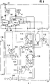
Fig. 2 is the circuit diagram of the water system middle controller of Fig. 1;
Fig. 3 is illustrated in the detail drawing of the terminal of an inverter in the controller;
Fig. 4 is the block diagram that is used to illustrate the software operation of inverter;
Fig. 5 is the flow process of basic software operative section that is used for the block diagram of explanatory drawing 4;
Fig. 6 is the flow chart that is used for illustrating the details that restarts operation of the inverter that is included in the basic software operation;
Fig. 7 is the example of the interlocking signal that utilizes when two inverters are used to send and receive interlocking signal in the present invention;
Fig. 8 is in the present invention when using three or more inverter, the example of the single interlocking signal of utilization;
Fig. 9 is the example that storage distributes when three or more inverter is used to send and receives interlocking signal among the present invention.
1 to 9 will describe one embodiment of the present of invention in detail with reference to the accompanying drawings.
Fig. 1 is used to illustrate the block diagram of arranging according to the integral body of the water system of one embodiment of the present of invention, Fig. 2 is the circuit diagram of the water system middle controller of Fig. 1, Fig. 3 represents each terminal details drawing of the device inverter controlled, Fig. 4 is the block diagram that is used to illustrate the software operation of inverter, Fig. 5 is the flow chart of substantial section that is used for the software operation of explanatory drawing 4 block diagrams, Fig. 6 is used for illustrating the flow chart of the details that restarts operation that is included in other inverters of basic software operation and other examples that Fig. 7 to 9 expression interlocking signal maybe can be applied to the signal of three or more inverter.
At first, comprise the control of the whole water supply of the controller 1 execution unit 2 of inverter 20,21 and drain circuit circuit breaker 40,41 with reference to Fig. 1.Water supply unit 2 comprises motor driving pump 105,106, pressure transducer 102,112, flow switch 107,117, influent side current composite tube 104, water supply or water outlet side current composite tube 110, pressure tank 111, pressure gauge 114,115 and other various types of valves 110,101,103,108,109 again.Utilize such arrangement, water supply unit 2 plays raising and is responsible for 116 hydraulic action to the water supply that water distribution pipe 118 supplies water.
Be applied on inverter 20 and 21 by water outlet side pressure transducer 112, pressure transducer 102 and flow switch 107 and 117 testing signals that detect, this inverter 2 is based on the testing signal of these receptions, the electric energy that conversion receives is the variable frequency AC energy, according to the pre-programmed drive scheme and provide this electric energy on motor driving pump 105 and 106, carry out constant pressure of supply water control or constant user side pressure control.
In Fig. 2; noise filter NF60 and zero phase reactor ZCL50 decay are superimposed on from principal current power supply 10 presents next electric noise; with protection inverter 20 and 21, and prevent to be fed to deliver in the principal current power supply 10 to go by the electric noise that the harmonic currents that inverter 20 and 21 produces cause. Zero phase reactor 51 and 52 suppresses from inverter 20 and 21 transient currents that will be added on motor driving pump 105 and 106, thereby reduces at drive motor pump 105 and the noise that produced in 106 o'clock.
Drain current circuit breaker 40 and 41 detects leakage currents, shocked by electricity to prevent the user, and also as in motor driving pump 105 and 106 and power supply on/off switch when the maintenance of inverter 20 and 21 and safety inspection.
What represent among Fig. 3 is each input/output terminal of inverter 20 and 21, and these terminals will be illustrated below in more detail.
Interlocking signal 61 links to each other with output signal terminal DO2 with 62; be used to notify other inverters; relevant inverter is because its own protective function (disconnection certainly) has been stopped work; input terminal DI1 is used to import from what other inverters came and restarts command signal (alternately ordering ENQ); input terminal DI2 is used to import and passes on other inverters to be used for output by its own protective function (its other party disconnects) out-of-work message and output signal terminal DO1 to restart command signal (alternately ordering ACK) and arrive other inverters.Sensor input end AI1 and AI2 are analog input ends, are used to receive the signal from pressure transducer 102 and 112.The signal FS that sends from flow switch 107 is applied to terminal FW as a bit signal.The signal that sends from digital actuator 30 and 31 is connected to serial communication port SD and RD.Provide bit output terminal DO1 to DO5 at present embodiment in addition, be used to notify a external equipment by inverter 20 and 21 improper detections.
Fig. 4 is the block diagram based on the operation of software that is used for illustrating the microcomputer that is contained in inverter 20 and 21.In the drawings, normal running square frame 401 has been stored pump and has been driven working procedure, goes out the output frequency of each inverter and driving/cease and desist order according to this working procedure based on the data computation of interlocking signal and pressure sensor signal.Square frame 401 sends its result of calculation to LAD action block 402.Square frame 402 is based on the characteristic of the output frequency that calculates and driving/cease and desist order and inverter, and the order that produces detailed output frequency and output voltage is represented and send this to order PWM action block 403.Square frame 403 output signal PWM (pulse width control signal) are used for driving the switching element at converter main circuit 407 to converter main circuit 407, produce the inversion of exporting the variable frequency electric energy according to output frequency that calculates and output voltage order.Excess current reference value as the excess load current detecting level of inverter sends to the opening operation square frame 404 that will be stored in wherein from normal running square frame 401.Opening operation square frame 404 constantly monitors excess current reference value and inverter load current and when detecting the excess load electric current, then produces disconnection information and send it to command process square frame 405.That also be applied to normal running square frame 401 is the voltage PN (voltage between the positive and negative level on the middle dc voltage) of converter main circuit, so that square frame 401 detects overvoltages or under-voltage or short-circuit voltage and sends this testing signal to opening operation square frame 404.Command process square frame 405 is carried out to receive and is handled operation, these operations comprise: from the abnormal operation of inverter opening operation square frame 404 (such as, overcurrent or overvoltage or under-voltage), based on the traffic operation of the key entry information of digital actuator 30 and 31, to the read-write operation of the nonvolatile storage (EEPROM) 408 of the output of the demonstration signal LED of digital actuator 30 and 31.EEPROM I/O action block 406, according to EPROM write order or the call request order that receives from command process square frame 405, directly visit nonvolatile storage 408 and execution need the transfer of stored that secondary data, even also be like this under the situation of power failure.These data such as, for the fault history data between the desired basic parameter of drive installation and square frame 406 and 405.
An example of normal running square frame 401 is illustrated in Fig. 5 in the flow chart mode.When power supply is added to inverter 20 and 21, normal running square frame 401 is carried out initialization step 501, read water supply target pressure HO from nonvolatile storage 408, minimum actuating speed NS, the highest actuating speed Nf, velocity variations width Delta N restarts judgement time T and restarts frequency m, as for the required parameter of pump drive controlling with these parameters are used for the inverter output frequency in register calculating is set.
Then, normal running square frame 401 execution in step 502, with respectively from pressure transducer 102 and 112 and the signal of flow switch 107 and 117 be added to sensor input terminal AI1, AI2 and FW.
Next, normal running square frame 401 execution in step 503 are utilized the serviceability of other inverters (hereinafter being called its other party inverter) in interlocking signal 61 and 62 input controllers 1 and are also exported its oneself serviceability to its other party inverter.
Then, normal running square frame 401 execution in step 504 are checked the serviceability of other inverters.When the serviceability of judging its other party is just often, normal running square frame 401 advances to a pump control step 505; Otherwise when the decision operation state was undesired, square frame 401 execution hereinafter with the step of describing in detail 510, were carried out the operation of restarting of its other party inverter in conjunction with Fig. 6, and step 401 advances to next pump control step 505 after this step.
Next step, square frame 401 is carried out pump control step 505, and current pressure of supply water H and water supply target pressure H0 are relatively in this step.If H>H0, then system advances to step 508 and 509, and execution speed increases operation; Otherwise if H0>H, then system proceeds to step 506 and 507, and execution speed reduces operation.When H=H0, do not carry out velocity variations.
Normal running square frame 401 turns back to execution in step 502 then, repeatedly carries out the same operation order.
Fig. 6 represents to be used for illustrating the flow chart of details of the step 510 that restarts of its other party inverter that is included in normal running square frame 401, and this flow chart will be described in detail as follows.
Undesired when the serviceability that is judged as its other party inversion by execution in step 504, carry out its other party and restart step 510.
Restart in the step 510 this side, the frequency MAXm that restarts of this inverter at first determines in step 601.A discharge time of the control circuit that restarts the same inverter of requirement of this inverter, promptly a common 3-5 second restarts the time.Restarting time durations, even pump quits work, be provided with pressure tank 111 in the present embodiment, to such an extent as to as long as water output (water requirement) is little, can prevent that also pressure of supply water from descending fast, this pressure tank 111 provides the execution inverter repeatedly to restart the time enough surplus of operation.Simultaneously, when the quantitative change that reduces to supply water along with time margin is big, then need to limit the frequency that restarts.Water output can directly detect by the traffic transport device, therefore can determine to restart frequency MAXm.But, because there is a predetermined relationship between revolution speed N, water supply flow Q and pressure of supply water H, this relation is that revolution speed N can be used to replace water output with the Q-H characteristic of revolution speed N as its parameter, determine to restart frequency MAXm, as shown in the step 7.That is to say, as as shown in the step 7, primary quantity m0 who restarts frequency according to water supply conditions is deposited with in the inverter in advance by digital actuator, to such an extent as to the higher revolution speed N in the fault time of inverter, promptly during the more water output in this fault time, be set up the less frequency MAXm value that restarts.
Then, in step 603, system sends and restarts order to improper inverter, waits for and restarts processing time T (being 3 seconds in the present embodiment), and confirm that this inverter is restarted in step 604.If this inverter is restarted in step 604, then system enters step 610, writes down its improper history and returns normal running.If do not restart, then system repeats to restart line loop by what step 605,609,603 and 604 formed.
When restarting frequency and reach MAXm, system's execution in step 607 as long as the pressure of supply water of pump is higher than minimal protection pressure H3, continues the operation of restarting of this inverter by step 607,609,602,603,604 and 605 loop.In step 607, when restarting frequency above MAXm, system attempts to pull out one and restarts order to this inverter even, to avoid the abnormal condition of this inverter, so that continue to supply water, as long as minimum assurance pressure H3 can access.
In step 607, when pressure of supply water is lower than minimum assurance pressure H3, system's execution in step 608.In step 608, system stops this inverter and carries out a kind of processing so that a kind of other drive pattern is set regularly in its abnormal condition, and other normal inverters are driven in this pattern, replace this improper inverter, also will send out a fault warning.
By with the above this repetitive operation, normal running square frame 401 is carried out the supervisory work of the state of its other party inverters, the improper time restart operation and the raw water service pump driving of variable velocity is simultaneously operated.
Though, in step 7, determined to restart frequency MAXm from revolution speed N, restarting frequency can be determined in such a way cursorily, promptly consider by pump and operate handled water output in the daytime usually greater than the water output of handling in its night time operation by pump at it, like this, in the daytime Cao Zuo the frequency that is less than night time operation that restarts the frequency setting.
Now refer again to Fig. 7 to 9, wherein represented other examples of interlocking signal 61 and 62, they are applied to having the system of three or more inverter.
In Fig. 7, the transmitter TXD of inverter 71 is connected to the receiving port RXD of inverter 72 through interlocking signal 12, be connected to the receiving port RXD of inverter 71 through interlocking signal 61 with the transmission mouth TXD of inverter 72, thereby, drive the mutual supervision of operation and drive the transmission of ordering (comprising the above-mentioned order of restarting) and can realize with 1: 1 serial communication relation.When the number of this inverter increases, for example increase to 3 or 4, this requires each inverter of inverter and its to communicate by letter, this causes the number of this transmission mouthful TXD and the number RXD of this receiving port must increase to 2 or 3 faultily, and the manufacture cost of inverter and communication channel will become high wastefully thus.
For fear of a kind of like this shortcoming, a kind of device shown in Figure 8 is such, and promptly each inverter is connected to such loop, and their transmission and receiving port TXD and RXD are via a single continuous interlocking signal coupling.In this case, when the data of all inverters with a kind of like this communication data form shown in Fig. 8 (a) are transmitted when being used to communicate by letter at above-mentioned loop, each inverter only requires to have a single transmission mouth TXD and a single receiving port RXD and is used for the purpose of communicating by letter with every other inverter.In Fig. 8 (a), at the symbol of the stem of each inversion data ' ST.NO " be to give each inverter uniquely, stipulate the inverter that data interrelate with it uniquely by means of the number of in illustrated example, distributing to each inverter.The back of " ST.NO. " is data " DATA ", and these data are to drive operation and the main body of the data representation of the monitored state of the driving order that will send, and that this data back is also followed is data " CRC ", is used for the error-detecting of executive communication data.Each inverter sends mouthful TXD through it and is sent in data in its oneself the transmission data buffer, is received among its receiving port RXD the data from every other inverter, and it is stored in its oneself the receive data buffer.
What Fig. 9 represented is the layout of storage in the above-mentioned buffer that transmits and receive data or an example of distribution.In Fig. 9, each inverter 1 to 4 has the transmission and the reception buffer of 1000 bytes store capacity, wherein distributes the sending area of 256 bytes in each buffer, so that not overlapping to each other at each buffer.Each inverter is communicated by letter with other inverters all the time, and is sent in data in its oneself the sending area as interlocking signal, monitors its oneself reception area all the time according to its oneself drive condition, with conversion or the abnormal condition that adapts to operation.
Although in the embodiment's of Fig. 9 situation, above-mentioned communications system is a kind of serial communication type, when the standard serial traffic rate with 19.5Kbps sends 1000 byte datas, about one second of its speed of response, this also is enough fast for pump control.
As above having explained; according to the present invention; a kind of device that restarts is provided; when an inverter is quit work by its oneself protective function; this device restarts out of order inverter by other inverters and restarts operation and is to be undertaken by its oneself inverter, thereby can realize dual control system; inverter can less frequency stops and water system can improved aspect its reliability.
In addition, because can eliminate necessity that a peripheral control unit is provided, the required part count of The whole control system can reduce, so cost can effectively reduce.
Claims (13)
1. water system comprises:
A plurality of inverters, these inverters have the protective gear that is used to protect them, so that produce the AC power of variable frequency according to a kind of driving operating process of pre-programmed;
A plurality of motors, these motors are connected on described each inverter, when from described inverter received power, by with a kind of variable speed driving; With
A plurality of variable speed pump when being connected to described each motor, are used for supplying water to the water supply distribution piping,
It is characterized in that also comprising the described protective gear that is used to monitor other inversions operation malfunction monitoring apparatus and be used to export the restart device of startup command to other inverters, the fault of these other inverters is detected by described malfunction monitoring apparatus.
2. according to the described water system of claim 1, it is characterized in that also comprising the water supply condition checkout gear, the water supply state and the wherein said device that restarts that are used to detect each described pump are determined restarting frequency and making other inverter restart out of order inverter of described inverter according to the water supplying pump state that is detected by described water supply condition checkout gear.
3. according to the described water system of claim 2, it is characterized in that, the described water supply condition checkout gear that is used for the pressure of supply water state of testing pump is that the pressure of supply water that is used for testing pump becomes less than a predetermined assurance pressure detector that guarantees pressure, with as long as the described pressure of supply water that guarantees that pressure detector detects described pump is higher than described predetermined assurance pressure, describedly restart the operation of restarting that device repeats inverter.
4. according to the described water system of claim 2, it is characterized in that also comprising storage device, be used for storing therein described inverter according to the value of the predetermined frequency that restarts of described water supplying pump state and wherein said restart device according to the water supply state of the pump that detects by described water supply condition checkout gear select to be stored in described storage device frequency that restarts and be equivalent to described selection restart frequency or littler number of times repeats to restart operation.
5. according to the described water system of claim 2, it is characterized in that, the said water supply condition checkout gear that is used for the water supply state of testing pump is to be used to detect the increase of water output of described pump or the device of minimizing, when increasing with the water output that detects pump when described water output increase/minimizing detection device, the described frequency that restarts that restarts device minimizing inverter.
6. according to the described water system of claim 2, it is characterized in that, the described water supply condition checkout gear that is used for the water supply state of testing pump is the pump speed detection device of an actuating speed that is used for testing pump and describedly restarts driving speed that device detects according to described pump speed detection device and determine the frequency that restarts.
7. according to the described water system of claim 2, it is characterized in that, the said water supply condition checkout gear that wherein is used for the water supply state of testing pump is to be used to detect a flow detector of water output and the described device that restarts according to the frequency of being determined by the water output of described flow detection to restart at its water supply side.
8. according to the described water system of claim 2, it is characterized in that, the described water supply condition checkout gear that is used for the water supply state of testing pump is to be used to detect that the predetermined water output that makes described pump will increase operates and be scheduled to make the device of the night time operation that the water output of described pump will reduce in the daytime and describedly restart the device setting and restart frequency and make the frequency that restarts of operating in the daytime at described device will be less than the frequency that restarts in described night time operation.
9. according to the described water system of claim 1; it is characterized in that; described malfunction monitoring apparatus comprises output unit; be used for when an inverter is quit work by its oneself protective gear, notifying other inverters; and input device; be used to receive the message that transmits when other inverters are quit work by its oneself protective gear; comprise output unit with the described device that restarts; be used for output and restart command signal, be used for restarting command signal from other inverter receptions to other inverters and output unit.
10. according to the described water system of claim 1; it is characterized in that; when described inverter was quit work by its oneself protective gear, the described device that restarts restarted the inverter that this is stopped in the predetermined constant time that this inverter quits work later.
11. according to the described water system of claim 1; it is characterized in that; when described inverter was quit work by its oneself protective gear, the described device that restarts restarted the inverter that is stopped with one with a corresponding number of times of frequency in scheduled frequency range.
12. a water system comprises:
A plurality of inverters, this inverter have its own protective gear of protection, so that according to a kind of AC power of driving operating process generation variable frequency of pre-programmed;
A plurality of motors are connected to described inverter, when from described inverter received power, by with variable speed drive; With
A plurality of variable speed pump are connected to described motor, are used for supplying water to the water supply distribution duct,
It is characterized in that:
Also comprise malfunction monitoring apparatus, be used to monitor the operation of the described protective gear of other inverters; Restart device, be used for to detecting out of order other inverter by described malfunction monitoring apparatus to export startup command with the predetermined corresponding number of times of a frequency that restarts in the frequency range; With a device, when it is detected out of order other inverter, reach described predetermined will be restarted after restarting frequency the time in the described startup command of output, be used to operate other normal inverters and replace the inverter that is stopped.
13. a water system comprises:
A plurality of inverters, this inverter have it and protect the protective gear of oneself, so that produce the AC power of variable frequency according to a kind of driving operating process of pre-programmed;
A plurality of motors are connected to described each inverter, when from described inverter received power, by with variable speed drive;
A plurality of variable speed pump are connected to described each motor, are used for supplying water to the water supply distribution duct; With
It is characterized in that also comprising
When any one inverter is quit work by its oneself protective gear, be used to respond the signal that sends from described out-of-work inverter, operate other normal inverter and replace this to be stopped the device of the inverter of work.
Applications Claiming Priority (6)
| Application Number | Priority Date | Filing Date | Title |
|---|---|---|---|
| JP224492/1994 | 1994-09-20 | ||
| JP224492/94 | 1994-09-20 | ||
| JP224495/1994 | 1994-09-20 | ||
| JP6224495A JPH0893679A (en) | 1994-09-20 | 1994-09-20 | Water supply equipment |
| JP6224492A JPH0893678A (en) | 1994-09-20 | 1994-09-20 | Water supply equipment |
| JP224495/94 | 1994-09-20 |
Publications (2)
| Publication Number | Publication Date |
|---|---|
| CN1119706A CN1119706A (en) | 1996-04-03 |
| CN1062338C true CN1062338C (en) | 2001-02-21 |
Family
ID=26526091
Family Applications (1)
| Application Number | Title | Priority Date | Filing Date |
|---|---|---|---|
| CN 95109699 Expired - Lifetime CN1062338C (en) | 1994-09-20 | 1995-07-31 | Water supply system |
Country Status (3)
| Country | Link |
|---|---|
| KR (1) | KR0165723B1 (en) |
| CN (1) | CN1062338C (en) |
| TW (1) | TW307814B (en) |
Families Citing this family (2)
| Publication number | Priority date | Publication date | Assignee | Title |
|---|---|---|---|---|
| KR100458961B1 (en) * | 2002-05-14 | 2004-12-03 | 신한일전기주식회사 | Method for controlling emergency operation of booster system |
| EP2573403B1 (en) * | 2011-09-20 | 2017-12-06 | Grundfos Holding A/S | Pump |
-
1995
- 1995-07-14 TW TW84107317A patent/TW307814B/zh not_active IP Right Cessation
- 1995-07-31 CN CN 95109699 patent/CN1062338C/en not_active Expired - Lifetime
- 1995-08-09 KR KR1019950024515A patent/KR0165723B1/en not_active IP Right Cessation
Also Published As
| Publication number | Publication date |
|---|---|
| TW307814B (en) | 1997-06-11 |
| KR0165723B1 (en) | 1999-03-20 |
| CN1119706A (en) | 1996-04-03 |
Similar Documents
| Publication | Publication Date | Title |
|---|---|---|
| US8714933B2 (en) | Water supply apparatus | |
| CN106787973B (en) | Drive control device and method for yaw motor of wind generating set | |
| JP2008202556A (en) | N-multiplex system autonomous distributed control system for water supply system | |
| CN1062338C (en) | Water supply system | |
| CN105020045A (en) | Controller with CAN bus | |
| KR100362517B1 (en) | Full range feedwater control system and method for pressurized water reactor steam generators | |
| CN102904328A (en) | Laser redundant backup power supply | |
| CN1215452A (en) | Turbomachinery driving apparatus and method of controlling the same | |
| JP3288625B2 (en) | Inverter | |
| CN106150995B (en) | A kind of pump control unit | |
| CN1042989C (en) | Load control module | |
| KR100676548B1 (en) | Contorolling system for intake using wireless communications and method thereof | |
| JPH10220388A (en) | Water supply device | |
| JP3086996B2 (en) | Sewer pump monitoring system | |
| KR100458961B1 (en) | Method for controlling emergency operation of booster system | |
| JP3005516B2 (en) | Water supply system | |
| KR100738572B1 (en) | H-bridge multi-level inverter having a dual controller | |
| CN217765141U (en) | Drainage auxiliary facilities comprehensive monitoring system and drainage device | |
| CN218030555U (en) | Water pump set with self-checking function | |
| CN215805093U (en) | Full frequency conversion constant pressure water supply control system | |
| KR200171310Y1 (en) | A Operation System of Cleaning System | |
| CN115473493A (en) | Photovoltaic system and method for operating same | |
| JP3556240B2 (en) | Pump control device | |
| SU1066505A1 (en) | Automatic irrigation system | |
| CN116025025A (en) | Modularized electric cabinet system and water supply monitoring method |
Legal Events
| Date | Code | Title | Description |
|---|---|---|---|
| C10 | Entry into substantive examination | ||
| SE01 | Entry into force of request for substantive examination | ||
| C06 | Publication | ||
| PB01 | Publication | ||
| C14 | Grant of patent or utility model | ||
| GR01 | Patent grant | ||
| CX01 | Expiry of patent term |
Expiration termination date: 20150731 Granted publication date: 20010221 |
|
| EXPY | Termination of patent right or utility model |