CN106062860B - Image processing apparatus, image processing method, and image display apparatus - Google Patents
Image processing apparatus, image processing method, and image display apparatus Download PDFInfo
- Publication number
- CN106062860B CN106062860B CN201580011090.7A CN201580011090A CN106062860B CN 106062860 B CN106062860 B CN 106062860B CN 201580011090 A CN201580011090 A CN 201580011090A CN 106062860 B CN106062860 B CN 106062860B
- Authority
- CN
- China
- Prior art keywords
- luminance signal
- image
- luminance
- dynamic range
- light emitting
- Prior art date
- Legal status (The legal status is an assumption and is not a legal conclusion. Google has not performed a legal analysis and makes no representation as to the accuracy of the status listed.)
- Active
Links
Images


Classifications
-
- G—PHYSICS
- G09—EDUCATION; CRYPTOGRAPHY; DISPLAY; ADVERTISING; SEALS
- G09G—ARRANGEMENTS OR CIRCUITS FOR CONTROL OF INDICATING DEVICES USING STATIC MEANS TO PRESENT VARIABLE INFORMATION
- G09G3/00—Control arrangements or circuits, of interest only in connection with visual indicators other than cathode-ray tubes
- G09G3/20—Control arrangements or circuits, of interest only in connection with visual indicators other than cathode-ray tubes for presentation of an assembly of a number of characters, e.g. a page, by composing the assembly by combination of individual elements arranged in a matrix no fixed position being assigned to or needed to be assigned to the individual characters or partial characters
- G09G3/34—Control arrangements or circuits, of interest only in connection with visual indicators other than cathode-ray tubes for presentation of an assembly of a number of characters, e.g. a page, by composing the assembly by combination of individual elements arranged in a matrix no fixed position being assigned to or needed to be assigned to the individual characters or partial characters by control of light from an independent source
- G09G3/3406—Control of illumination source
- G09G3/342—Control of illumination source using several illumination sources separately controlled corresponding to different display panel areas, e.g. along one dimension such as lines
- G09G3/3426—Control of illumination source using several illumination sources separately controlled corresponding to different display panel areas, e.g. along one dimension such as lines the different display panel areas being distributed in two dimensions, e.g. matrix
-
- G—PHYSICS
- G09—EDUCATION; CRYPTOGRAPHY; DISPLAY; ADVERTISING; SEALS
- G09G—ARRANGEMENTS OR CIRCUITS FOR CONTROL OF INDICATING DEVICES USING STATIC MEANS TO PRESENT VARIABLE INFORMATION
- G09G3/00—Control arrangements or circuits, of interest only in connection with visual indicators other than cathode-ray tubes
- G09G3/20—Control arrangements or circuits, of interest only in connection with visual indicators other than cathode-ray tubes for presentation of an assembly of a number of characters, e.g. a page, by composing the assembly by combination of individual elements arranged in a matrix no fixed position being assigned to or needed to be assigned to the individual characters or partial characters
- G09G3/2092—Details of a display terminals using a flat panel, the details relating to the control arrangement of the display terminal and to the interfaces thereto
-
- G—PHYSICS
- G09—EDUCATION; CRYPTOGRAPHY; DISPLAY; ADVERTISING; SEALS
- G09G—ARRANGEMENTS OR CIRCUITS FOR CONTROL OF INDICATING DEVICES USING STATIC MEANS TO PRESENT VARIABLE INFORMATION
- G09G3/00—Control arrangements or circuits, of interest only in connection with visual indicators other than cathode-ray tubes
- G09G3/20—Control arrangements or circuits, of interest only in connection with visual indicators other than cathode-ray tubes for presentation of an assembly of a number of characters, e.g. a page, by composing the assembly by combination of individual elements arranged in a matrix no fixed position being assigned to or needed to be assigned to the individual characters or partial characters
- G09G3/34—Control arrangements or circuits, of interest only in connection with visual indicators other than cathode-ray tubes for presentation of an assembly of a number of characters, e.g. a page, by composing the assembly by combination of individual elements arranged in a matrix no fixed position being assigned to or needed to be assigned to the individual characters or partial characters by control of light from an independent source
- G09G3/3406—Control of illumination source
- G09G3/3413—Details of control of colour illumination sources
-
- G—PHYSICS
- G09—EDUCATION; CRYPTOGRAPHY; DISPLAY; ADVERTISING; SEALS
- G09G—ARRANGEMENTS OR CIRCUITS FOR CONTROL OF INDICATING DEVICES USING STATIC MEANS TO PRESENT VARIABLE INFORMATION
- G09G3/00—Control arrangements or circuits, of interest only in connection with visual indicators other than cathode-ray tubes
- G09G3/20—Control arrangements or circuits, of interest only in connection with visual indicators other than cathode-ray tubes for presentation of an assembly of a number of characters, e.g. a page, by composing the assembly by combination of individual elements arranged in a matrix no fixed position being assigned to or needed to be assigned to the individual characters or partial characters
- G09G3/34—Control arrangements or circuits, of interest only in connection with visual indicators other than cathode-ray tubes for presentation of an assembly of a number of characters, e.g. a page, by composing the assembly by combination of individual elements arranged in a matrix no fixed position being assigned to or needed to be assigned to the individual characters or partial characters by control of light from an independent source
- G09G3/36—Control arrangements or circuits, of interest only in connection with visual indicators other than cathode-ray tubes for presentation of an assembly of a number of characters, e.g. a page, by composing the assembly by combination of individual elements arranged in a matrix no fixed position being assigned to or needed to be assigned to the individual characters or partial characters by control of light from an independent source using liquid crystals
-
- G—PHYSICS
- G09—EDUCATION; CRYPTOGRAPHY; DISPLAY; ADVERTISING; SEALS
- G09G—ARRANGEMENTS OR CIRCUITS FOR CONTROL OF INDICATING DEVICES USING STATIC MEANS TO PRESENT VARIABLE INFORMATION
- G09G2320/00—Control of display operating conditions
- G09G2320/02—Improving the quality of display appearance
- G09G2320/0271—Adjustment of the gradation levels within the range of the gradation scale, e.g. by redistribution or clipping
- G09G2320/0276—Adjustment of the gradation levels within the range of the gradation scale, e.g. by redistribution or clipping for the purpose of adaptation to the characteristics of a display device, i.e. gamma correction
-
- G—PHYSICS
- G09—EDUCATION; CRYPTOGRAPHY; DISPLAY; ADVERTISING; SEALS
- G09G—ARRANGEMENTS OR CIRCUITS FOR CONTROL OF INDICATING DEVICES USING STATIC MEANS TO PRESENT VARIABLE INFORMATION
- G09G2320/00—Control of display operating conditions
- G09G2320/06—Adjustment of display parameters
- G09G2320/0626—Adjustment of display parameters for control of overall brightness
- G09G2320/0646—Modulation of illumination source brightness and image signal correlated to each other
-
- G—PHYSICS
- G09—EDUCATION; CRYPTOGRAPHY; DISPLAY; ADVERTISING; SEALS
- G09G—ARRANGEMENTS OR CIRCUITS FOR CONTROL OF INDICATING DEVICES USING STATIC MEANS TO PRESENT VARIABLE INFORMATION
- G09G2320/00—Control of display operating conditions
- G09G2320/06—Adjustment of display parameters
- G09G2320/066—Adjustment of display parameters for control of contrast
-
- G—PHYSICS
- G09—EDUCATION; CRYPTOGRAPHY; DISPLAY; ADVERTISING; SEALS
- G09G—ARRANGEMENTS OR CIRCUITS FOR CONTROL OF INDICATING DEVICES USING STATIC MEANS TO PRESENT VARIABLE INFORMATION
- G09G2320/00—Control of display operating conditions
- G09G2320/06—Adjustment of display parameters
- G09G2320/0673—Adjustment of display parameters for control of gamma adjustment, e.g. selecting another gamma curve
-
- G—PHYSICS
- G09—EDUCATION; CRYPTOGRAPHY; DISPLAY; ADVERTISING; SEALS
- G09G—ARRANGEMENTS OR CIRCUITS FOR CONTROL OF INDICATING DEVICES USING STATIC MEANS TO PRESENT VARIABLE INFORMATION
- G09G2360/00—Aspects of the architecture of display systems
- G09G2360/14—Detecting light within display terminals, e.g. using a single or a plurality of photosensors
- G09G2360/141—Detecting light within display terminals, e.g. using a single or a plurality of photosensors the light conveying information used for selecting or modulating the light emitting or modulating element
Abstract
An image processing apparatus may include a processing device that determines a degree of degradation of high luminance signal information of an input image and obtains a luminance signal curve based on the degree of degradation.
Description
Cross Reference of Related Applications
This application claims the benefit of prior japanese patent application JP2014-042857 filed on 5/3/2014 and prior japanese patent application JP2014-245564 filed on 4/12/2014, each of which is incorporated herein by reference in its entirety.
Technical Field
The technology disclosed in the present disclosure relates to an image processing apparatus and an image processing method that perform luminance dynamic range conversion processing of an image, and an image display device.
Background
In recent years, a technique of High Dynamic Range (HDR) imaging is being developed due to an imaging element (image sensor) of a high level or the like. HDR is a technology intended to represent an image closer to the real world, and has advantages in that shadows can be represented realistically, exposure is simulated, glare is represented, and the like. Meanwhile, since high brightness information is compressed using photographing or editing in a Standard Dynamic Range (SDR) image, the dynamic range becomes small, and it is difficult to declare that it represents the real world.
For example, an imaging apparatus that presents an HDR image composed of a plurality of imaged images different in exposure amount (see PTL1, for example).
Cameras used for content reproduction typically have the capability to take HDR images. However, the reality is that the image is converted into an image whose dynamic range is compressed to a standard brightness of about 100 nits, edited, and then provided to the content user. The form of providing content is various and there are digital broadcasting, streaming delivery over the internet, media sales, and the like. For a content producer, the brightness of a main monitor for editing content is about 100 nits, high-brightness signal information at the time of initial production is compressed, the gradation thereof is destroyed, and the sense of realism is lost.
Further, luminance dynamic range conversion in which an image is converted from an HDR image to an SDR image using knee compression may be performed. Knee compression is a method in which a high luminance portion of a signal is suppressed so that the luminance of an image falls within a predetermined dynamic range (here, the dynamic range of SDR). Knee compression is a method of compressing a dynamic range for a luminance signal exceeding a predetermined luminance signal level (signal level) called Knee point (Knee point) by reducing the inclination of input-output characteristics (for example, see PTL 2). The knee point is set below the desired maximum luminance signal level.
In recent years, high brightness displays having a maximum brightness of 500 nits or 1000 nits are commercially available. However, as described above, since an image is provided after being compressed into the dynamic range of an SDR image, regardless of the fact that the image is produced as an HDR image, initially, there is a wasteful case of browsing the SDR image using a high brightness display brighter than a main monitor whose white brightness is 100 nits.
In order to enjoy an SDR image set in the form of television broadcasting, streaming, or media as an initial HDR image using a high brightness display, Knee extension (Knee extension) processing may be performed. When knee expansion is performed, the reverse of the knee compression process may be performed. The input and output luminance positions at which the suppression of the knee point (i.e., suppression of the signal level) is initiated and the maximum luminance level being suppressed may be used to define a method of knee compression. However, when the definition information of knee compression is delivered only as an incomplete form, or is not completely delivered from a broadcasting station (or a supply source of images), an accurate method of performing knee extension cannot be determined on the receiver side. When the expansion processing of the luminance dynamic range is performed by an inaccurate method, there are problems as follows: the compressed high intensity signal information cannot be recovered and the knee compression when editing is performed cannot be recovered.
Reference list
Patent document
PTL 1:JP 2013-255301A
PTL 2:JP 2006-211095A
PTL 3:JP 2008-134318A
PTL 4:JP 2011-221196A
PTL 5:JP 2014-178489A
PTL 6:JP 2011-18619A
Disclosure of Invention
Technical problem
It is desirable to provide an excellent image processing apparatus and image processing method and image display device capable of converting an image compressed in a low dynamic range or a standard dynamic range into an initial high dynamic range image.
Problems to be solved
According to an embodiment of the present disclosure, an image processing apparatus may include a processing device that determines a degree of degradation of high luminance signal information of an input image and obtains a luminance signal curve based on the degree of degradation.
According to an embodiment of the present disclosure, an image processing method may include: a degree of degradation of high luminance signal information of an input image is determined by a processing device, and a luminance signal curve is obtained based on the degree of degradation by the processing device.
According to an embodiment of the present disclosure, a non-transitory storage medium may be recorded with a program for performing image processing, and the program may include determining a degree of degradation of high luminance signal information of an input image and obtaining a luminance signal curve based on the degree of degradation.
According to an embodiment of the present disclosure, a display device may include: a processing device that determines a degree of degradation of high luminance signal information of an input image and obtains a luminance signal curve based on the degree of degradation; and a display device including a backlight configured by a plurality of light emitting units, wherein the processing device controls power of the individual light emitting units according to the luminance signal curve.
According to an embodiment of the present disclosure, there is provided an image processing apparatus including: a determination unit that determines a degree of degradation of high luminance signal information of an input image; and an adjusting unit that adjusts the input image based on a determination result of the usage determining unit.
In the image processing apparatus, the adjusting unit may include: a luminance correcting unit that corrects luminance based on a result of the determination using the determining unit; a luminance signal correction unit correcting a luminance signal according to the gradation; and a color signal correction unit correcting a change in hue as needed, the change in hue being associated with the correction of the luminance signal.
In the image processing apparatus, the luminance correcting unit may improve the luminance in all the gradations in accordance with the degree of degradation of the high-luminance signal information determined by the determining unit.
In the image processing apparatus, the luminance signal correction unit may optimize the signal curve with respect to the degraded gradation and the non-degraded gradation.
In the image processing apparatus, when the change in hue is associated with the correction of the luminance signal performed using the luminance signal correction unit, the color signal correction unit may maintain the initial hue by performing inversion correction on the change.
In the image processing apparatus, the color signal correction unit may correct the chrominance signal so that a ratio of the luminance signal to the chrominance signal becomes constant before and after the luminance signal is corrected.
In the image processing apparatus, the determination unit may determine the degree of degradation of the high luminance signal information thereof based on a luminance level (luminance level) of the input image.
In the image processing apparatus, the determination unit may determine the degree of degradation of the high luminance signal information based on at least one of a maximum luminance signal level in the input image, an amount in the vicinity of a value of the maximum luminance signal level in the input image, an average value of luminance signals in the input image, and an amount in the vicinity of a value of a black (low luminance signal) level of the input image.
According to another embodiment of the present disclosure, there is provided an image processing method including: determining a degradation degree of high luminance signal information of an input image; and adjusting the input image based on the determination result in the determination.
According to still another embodiment of the present disclosure, there is provided an image display apparatus including: a determination unit that determines a degree of degradation of high luminance signal information of an input image; an adjusting unit that adjusts the input image based on a determination result of the usage determining unit; and a display unit displaying the adjusted image.
Advantageous effects of the disclosure
According to the technique disclosed in the present disclosure, it is possible to provide an excellent image processing apparatus and image processing method and image display apparatus capable of reproducing luminance in real space by converting an image compressed in a low dynamic range or a standard dynamic range into an initial high dynamic range image.
Further, the effects described in the present disclosure are merely examples, and the effects of the technology are not limited thereto. Further, in addition to the effects described in the above-described technologies, there are cases where additional effects are exerted.
Further, another object, feature, or advantage of the technology disclosed in the present disclosure may become apparent with further detailed description based on embodiments or drawings to be described later.
Drawings
Fig. 1 is a diagram schematically showing a configuration example of an image display apparatus to which the technique disclosed in the present disclosure is applied.
Fig. 2 is a diagram schematically showing a configuration example when the display unit is a liquid crystal display method.
Fig. 3 is a diagram showing an exemplary process presented in the present disclosure for converting an image in a low luminance dynamic range or a standard luminance dynamic range into a high dynamic range image.
Fig. 4 is a diagram showing a state where an input image is subjected to luminance correction.
Fig. 5 is a diagram showing a state of luminance of an input image after optimizing luminance correction using luminance signal correction.
Fig. 6 is a diagram showing a functional configuration in which the chrominance signal is corrected so that the ratio of the luminance signal to the chrominance signal becomes constant before and after the luminance signal is corrected.
Fig. 7 is a diagram describing a technique of partial driving and pushing force (hammering).
Fig. 8 is a diagram describing a technique of partial driving and thrust.
Fig. 9 is a diagram describing a technique of partial driving and thrust.
Fig. 10 is a diagram schematically showing a configuration example of an image processing apparatus to which the technique disclosed in the present disclosure is applicable.
Fig. 11 is a diagram schematically showing a configuration example of an image processing apparatus to which the technique disclosed in the present disclosure is applicable.
Fig. 12 is a diagram schematically showing a configuration example of an image processing apparatus to which the technique disclosed in the present disclosure is applicable.
Fig. 13 is a diagram illustrating a luminance signal histogram of an input image.
[ FIG. 14 ]]FIG. 14 is a graph illustrating the degree of degradation K of exemplary high luminance signal information1Diagram of a table relative to a maximum luminance signal level.
[ FIG. 15 ]]FIG. 15 is a graph illustrating the degree of degradation K of exemplary high luminance signal information2A graph of a table relative to quantities around the value of the maximum luminance signal level.
[ FIG. 16 ] A]FIG. 16 depicts an exemplary degradation of high brightness signal informationDegree K3Graph of a table relative to the average value of a luminance signal.
[ FIG. 17 ]]FIG. 17 is a graph illustrating the degree of degradation K of exemplary high luminance signal information4A graph of a table relative to quantities around the value of the black level.
Fig. 18 is a diagram showing an example of a functional configuration for performing luminance signal correction and color signal correction in an RGB space.
Fig. 19 is a diagram showing in detail the configuration of a liquid crystal display panel, a backlight, and a driving unit thereof.
Fig. 20 is a conceptual diagram showing a part of the drive circuit shown in fig. 19.
Fig. 21 is a diagram schematically showing a configuration example of a direct-type backlight.
Fig. 22 is a view showing a cross section of a light guide plate having a single-layer structure.
Fig. 23A is a diagram illustrating the structure of a pixel arrangement.
Fig. 23B is a diagram illustrating the structure of the pixel arrangement.
Fig. 23C is a diagram illustrating the structure of the pixel arrangement.
Fig. 23D is a diagram illustrating the structure of the pixel arrangement.
Fig. 24 is a view schematically showing an example of a cross-sectional configuration of an edge-lit backlight using a multilayer light guide plate.
Fig. 25 is a diagram showing a state of a light emitting surface (light output surface) of the backlight shown in fig. 24 seen from above.
Detailed Description
Hereinafter, embodiments of the technology disclosed in the present disclosure will be described in detail with reference to the accompanying drawings.
Fig. 1 schematically shows a configuration example of an image display apparatus 100 to which the technique disclosed in the present disclosure can be applied.
Transmission radio waves of terrestrial radio wave digital broadcasting, satellite digital broadcasting, and the like are input to the antenna 101. The tuner 102 selectively amplifies a desired radio wave in a signal supplied from the antenna 101 and performs frequency conversion. The digital demodulation unit 103 detects a received signal subjected to frequency conversion, demodulates the signal (broadcast station side) using a method corresponding to the digital modulation method at the time of transmission, and also performs transmission error correction. Digital decoding section 104 outputs Y, Cb and the image signal of Cr to display section 105 by decoding the digital demodulation signal.
Fig. 10 shows another configuration example of the image display apparatus 100 to which the technique disclosed in the present disclosure can be applied. The same configuration elements as those in the device configuration shown in fig. 1 are given the same reference numerals. The medium reproducing unit 111 reproduces a signal recorded in a recording medium such as a blu-ray disc, a Digital Versatile Disc (DVD), or the like. The digital demodulation unit 103 detects a reproduced signal, demodulates the reproduced signal using a method corresponding to the digital modulation method at the time of recording, and also performs correction of a transmission error. The digital decoding unit 104 decodes the digital demodulation signal, and outputs Y, Cb and the image signal of Cr to the display unit 105.
Further, fig. 11 shows still another configuration example of the image display apparatus 100 to which the technique disclosed in the present disclosure can be applied. The same configuration elements as those in the device configuration shown in fig. 1 are given the same reference numerals. For example, the communication unit 121 is configured as a Network Interface Card (NIC), and receives an image stream delivered through a network protocol (IP) network such as the internet. The digital demodulation unit 103 detects a received signal, demodulates the signal using a method corresponding to a digital modulation method at the time of transmission, and also performs correction of a transmission error. The digital decoding unit 104 decodes the digital demodulation signal, and outputs Y, Cb and the image signal of Cr to the display unit 105.
Further, fig. 12 shows another configuration example of the image display apparatus 100 to which the technique disclosed in the present disclosure can be applied. The same configuration elements as those in the device configuration shown in fig. 1 are given the same reference numerals. A high definition multimedia interface (HDMI, registered trademark) unit 131 receives an image signal reproduced using a media reproduction apparatus such as a blu-ray disc player, for example, through an HDMI (registered trademark) cable. The digital demodulation unit 103 detects a received signal, demodulates the signal using a method corresponding to a digital modulation method at the time of transmission, and also performs correction of a transmission error. The digital decoding unit 104 decodes the digital demodulation signal, and outputs Y, Cb and the image signal of Cr to the display unit 105.
Fig. 2 schematically shows an example of the internal configuration of the display unit 105 of the liquid crystal display method. However, the liquid crystal display method is merely an example, and the display unit 105 may have another method.
The video decoder 202 performs signal processing (such as chrominance processing) on the image signal input from the digital decoding unit 104 through the input terminal 201, converts the signal into an RGB image signal having a resolution suitable for driving the liquid crystal display panel 207, and outputs the signal to the control signal generating unit 203 together with the horizontal synchronization signal H and the vertical synchronization signal V.
The control signal generation unit 203 generates image signal data based on the RGB data supplied from the video decoder 202, and supplies the data to the video encoder 204 together with the horizontal synchronization signal H and the vertical synchronization signal V. According to an embodiment, the control signal generation unit 203 also performs a process (to be described later) of converting an image of a low dynamic range or a standard dynamic range into an image of a high dynamic range.
The video encoder 204 provides respective control signals for causing the data driver 205 and the gate driver 206 to operate in synchronization with the horizontal synchronization signal H and the vertical synchronization signal V. Further, the video encoder 204 generates a light intensity control signal for individually controlling the light emitting diode units of the backlight 208 according to the luminance of the image signal, and supplies the light intensity control signal to the backlight drive control unit 209.
The data driver 205 is a driving circuit as follows: outputs a drive voltage based on the image signal, generates a signal applied to the data line based on the timing signal and the image signal transmitted from the video encoder 204, and outputs the signal. Further, the gate driver 206 is a driving circuit as follows: signals for sequential driving are generated, and a driving voltage is output to a gate bus line connected to each pixel in the liquid crystal display panel 207 in accordance with a timing signal transmitted from the video encoder 204.
For example, the liquid crystal display panel 207 has a plurality of pixels arranged in a grid shape. The liquid crystal molecules in a predetermined alignment state are enclosed between transparent plates such as glass, and an image is displayed according to a signal applied from the outside. As described above, the application of signals to the liquid crystal display panel 207 is performed using the data driver 205 and the gate driver 206.
The backlight 208 is a surface lighting device that is arranged on the rear side of the liquid crystal display panel 207, illuminates the liquid crystal display panel 207 with light from the rear side, and makes visible an image displayed on the liquid crystal display panel 207. The backlight 208 may have a direct type structure in which a light source is disposed directly below the liquid crystal display panel 207, or an edge-illumination type structure in which a light source is disposed at the periphery of a light guide plate. As the light source of the backlight 208, a Light Emitting Diode (LED) of R, G, or B, a white LED, or a laser light source may be used.
The backlight drive control unit 209 individually controls the luminance of each of the light emitting diode units of the backlight 208 in accordance with the light intensity control signal supplied from the control signal generation unit 203. The backlight driving control unit 209 may control the light intensity of each of the light emitting diode units according to the amount of power supplied from the power supply 210. Further, a technique of partial driving (to be described later) may be applied in which a screen is divided into a plurality of illumination areas, and the backlight driving control unit 209 controls the luminance of the backlight 208 in each area according to the position of the illumination area and a display signal.
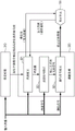
Fig. 19 shows in detail the configurations of the liquid crystal display panel 207 and the backlight 208 in the display unit 105 and the driving unit thereof. Further, fig. 20 shows a conceptual diagram of a part of the driving circuit in fig. 19. In the illustrated configuration example, it is assumed that partial driving of the display unit 105 can be performed.
The liquid crystal display panel 207 includes M0*N0I.e. M along the first direction0Pixel and N along a second direction0A display area 11 in which the total pixels of the pixels are arranged in a matrix form. Specifically, for example, the display area satisfies the HD-TV standard, and the resolution of the image display is (192)0,1080) and, for example, when pixel M is0*N0Is arranged in the form of a matrix, by (M)0,N0) And (4) showing. Further, when the partial driving is performed, the display region 11 (indicated by a chain line in fig. 19) configured by the pixels arranged in a matrix is divided into P × Q virtual display region units 12 (indicated by a broken line as a boundary). The value of (P, Q) is, for example, (19, 12). However, in order to simplify the drawing, the number of display area units 12 in fig. 19 (and a light source unit 42 (see fig. 21) to be described below) is different from this value. Each display area unit 12 is configured by a plurality of (M × N) pixels, and the number of pixels configuring one display area unit 12 is, for example, about ten thousand.
Each pixel is configured as a set of multiple sub-pixels emitting different colors, respectively. More specifically, each pixel is configured by three sub-pixels of a pixel (sub-pixel R) emitting red light, a pixel (sub-pixel G) emitting green light, and a pixel (sub-pixel B) emitting blue light. The display unit 105 is shown undergoing row sequential driving. More specifically, the liquid crystal display panel 207 includes scan electrodes (extending in a first direction) and data electrodes (extending in a second direction) intersecting each other in a matrix, selects the scan electrodes by inputting scan signals to the scan electrodes, scans the scan electrodes, displays an image based on data signals (signals based on control signals) input to the data electrodes, and configures one screen.
The backlight 208 is a surface lighting device disposed at the rear side of the liquid crystal display panel 207, and illuminates the display area 11 from the rear surface, and may have a direct-under type structure in which a light source is disposed directly below the liquid crystal display panel 207, or an edge-lighting type structure in which a light source is disposed at the periphery of a light guide plate. Further, when the partial driving is performed, the backlight 208 is configured by P × Q light source units 42 (see fig. 21) arranged individually for the dummy display region units 12 corresponding to P × Q. Each light source unit 42 illuminates the display area unit 12 corresponding to the light source unit 42 from the rear surface. Further, the light sources arranged in the light source unit 42 are controlled separately. Further, a light guide plate is disposed in each light source unit 42.
Further, the backlight 208 is actually arranged right below the liquid crystal display panel 207; however, in fig. 19, the liquid crystal display panel 207 and the backlight 208 are shown separately for convenience. In fig. 21, a configuration example of the direct type backlight 208 is schematically shown. In the example shown in fig. 21, the backlight 208 is configured by a plurality of light source units 42 respectively partitioned using light shielding spacers 2101. Each light source unit 42 includes a unit light emitting module in which a predetermined number of combinations of a plurality of types of single-color light sources are made. In the illustrated example, the unit light emitting modules are configured by light emitting diode cells in which light emitting diodes 41R, 41G, and 41B formed by the three primary colors of RBG are arranged as one group. For example, the red light emitting diode 41R emits red (for example, the wavelength is 640nm), the green light emitting diode 41G emits green (for example, the wavelength is 530nm), and the blue light emitting diode 41B emits blue (for example, the wavelength is 450 nm). Although it is difficult to understand in fig. 21 which is a plan view, the light-shielding separator 2101 is erected orthogonally on the mounting surface of each monochromatic light source, and good gradation control is performed by reducing leakage of irradiated light between each of the unit light-emitting modules. Further, in the example shown in fig. 21, each light source unit 42 divided using the light shielding separator 2101 has a rectangular shape; however, the shape of the light source unit is arbitrary. For example, the shape may be a triangular shape, or a honeycomb shape.
As shown in fig. 19 and 20, a driving unit that drives the liquid crystal display panel 207 and the backlight 208 based on an image signal input from the outside (e.g., the video encoder 204) is configured by a backlight driving control unit 209 that performs on-off configuring the red light emitting diodes 41R, the green light emitting diodes 41G, and the blue light emitting diodes 41B of the backlight 40 based on a pulse width modulation control method, the light source unit driving circuit 80, and the liquid crystal display panel driving circuit 90.
The backlight drive control unit 209 is configured by the operation circuit 71 and the storage unit (memory) 72. Further, when the partial driving is performed, the light emitting state of the light source unit 42 corresponding to the corresponding display area unit 12 is controlled based on the maximum input signal in the display area unitThe display area unit has a maximum value x in the input signal corresponding to each display area unit 12U-max。
Further, the light source unit driving circuit 80 is configured by an operation circuit 81, a storage unit (memory) 82, an LED driving circuit 83, a photodiode control circuit 84, switching elements 85R, 85G, and 85B formed of FETs, and a light emitting diode driving power supply (constant current source) 86.
Further, the liquid crystal display panel drive circuit 90 is configured by a well-known circuit which is a timing controller 91. In the liquid crystal display panel 207, a gate driver, a source driver, and the like (one of them is also not shown) for driving switching elements formed of TFTs configuring liquid crystal cells are provided. A feedback mechanism is formed in which the light emission state of each of the light emitting diodes 41R, 41G, and 41B in a certain image display frame is measured using the photodiodes 43R, 43G, and 43B, respectively, the outputs from the photodiodes 43R, 43G, and 43B are input to the photodiode control circuit 84, the outputs are set as data (signals) as, for example, the luminance and chromaticity of the light emitting diodes 41R, 41G, and 41B in the photodiode control circuit 84 and the operation circuit 81, the data is transmitted to the LED drive circuit 83, and the light emission states of the light emitting diodes 41R, 41G, and 41B in a subsequent image display frame are controlled. Further, a resistance element R for detecting a current is inserted in series with the light emitting diodes 41R, 41G, and 41B on the downstream side of the light emitting diodes 41R, 41G, and 41B, respectivelyR、rGAnd rB. In addition, in the resistance element rR、rGAnd rBThe flowing current causes a voltage change, and the operation of the light emission driving power supply 86 is controlled under the control of the LED driving circuit 83 so that the resistance element rR、rGAnd rBBecomes a predetermined value. Here, in fig. 5, only one light emission driving power supply (constant current source) 86 is shown; however, actually, light emission driving power supplies 86 for driving the light emitting diodes 41R, 41G, and 41B, respectively, are arranged.
When the partial driving is performed, the display region configured by the pixels arranged in a matrix is divided into P × Q display region units. When this state is expressed using "rows" and "columns", it can be said that the display area is divided into display area cells of Q rows by P columns. In addition, the display area unit 12 is configured by a plurality of (M × N) pixels; however, when this state is expressed using "rows" and "columns", it can be said that the display area cells are configured by N rows × M columns.
Each pixel is configured by a set of three sub-pixels of a sub-pixel (R) (a sub-pixel emitting red light), a sub-pixel (G) (a sub-pixel emitting green light), and a sub-pixel (B) (a pixel emitting blue light). E.g. 2 from 0 to 2558The gray scale control may be performed on the respective luminances of the sub-pixels (R, G, B). In this case, the value x of the input signal (R, G, B) input to the liquid crystal display panel drive circuit 90R、xGAnd xBRespectively have 28The value of the stage. In addition, the value S of the pulse width modulation output signal for controlling the number of times of light emission (lighting times) of the red light emitting diode 41R, the green light emitting diode 41G, and the blue light emitting diode 41B configuring each light source unitR、SG、SBAlso having 2 of 0 to 2558The value of the stage. However, it is not limited to this, and for example, 2 of 0 to 1023 may be performed by setting 10-bit control (expression using a numerical value of 8 bits may become 4 times, for example)10Control of the number of times the stage emits light.
For controlling the light transmittance LtIs supplied from the driving unit to each pixel. In particular, for controlling each light transmittance LtIs supplied from the liquid crystal display panel driving circuit 90 to the sub-pixel (R, G, B). That is, in the liquid crystal display panel drive circuit 90, a control signal (R, G, B) is generated from an input signal (R, G, B) that is input, and the control signal (R, G, B) is supplied (output) to the sub-pixel (R, G, B). Further, since the light source luminance Y of the backlight 208 or the light source unit 42 changes substantially in each pixel display frame, the control signal (R, G, B) has a value that corrects (compensates) the value of the input signal (R, G, B) subjected to the γ correction based on the change in the light source luminance Y. In addition, a control signal (R, G, B) is provided to configure the liquid crystalThe timing controller 91 of the display panel drive circuit 90 is transmitted to the gate driver and the source driver of the liquid crystal display panel 207, and the light transmittance (aperture ratio) L of each sub-pixel when the switching element configuring each sub-pixel is driven based on the control signal (R, G, B)tIs controlled, and a desired voltage is applied to the transparent electrode configuring the liquid crystal element. Here, the greater the value of the control signal (R, G, B), the greater the light transmittance (aperture ratio of the sub-pixel) L of the sub-pixel (R, G, B)tThe higher and the higher the luminance (display luminance y) value of the sub-pixel (R, G, B). That is, an image (generally, one type, and in a dot shape) configured using light passing through the sub-pixel (R, G, B) becomes bright.
The control of the display luminance Y and the light source luminance Y is performed in each image display frame in the image display of the display unit 105, each display region unit, and each light source unit. Further, the operation of the liquid crystal display panel 207 and the operation of the backlight 208 in one image display frame are synchronized.
Fig. 19 and 20 show a configuration example of the display unit 105 using a liquid crystal display; however, even when a device other than a liquid crystal display is used, the technique disclosed in the present disclosure can be similarly performed. For example, according to the technique disclosed in the present disclosure, a MEMS display (see, for example, PTL5) in which a MEMS shutter is driven on a TFT substrate may be applied.
Further, the technology disclosed in the present disclosure is not limited to a specific pixel arrangement structure of a three primary color pixel structure such as RGB. For example, the structure may be a pixel structure including one or more colors other than three primary color pixels of RGB, and specifically, the structure may be a four primary color pixel structure including RGBW of a white pixel other than three primary color pixels of RGB, or a four primary color pixel structure including RGBY of a yellow pixel other than three primary color pixels of RGB.
In fig. 23A to 23D, a pixel arrangement structure is illustrated. In fig. 23A, one pixel is configured by three sub-pixels of RGB, and the resolution thereof is 1920 × RGB (3) × 1080. Further, in fig. 23B, one pixel is configured by two sub-pixels of RG or BW, and the resolution thereof is 1920 × RGBW (4) × 2160. Further, in fig. 23C, two pixels are configured by five sub-pixels of RGBW, and the resolution thereof is 2880 × RGBW (4) × 2160. Further, in fig. 23D, one pixel is configured by three sub-pixels of RGB, and the resolution thereof is 3840 × RGB (3) × 2160. Further, the techniques disclosed in this disclosure are not limited to a particular resolution.
Further, the backlight 208 may have an edge-illumination type structure in which light sources are arranged at the periphery of a light guide plate, in addition to a direct type structure (as described above) in which light sources are arranged directly below the liquid crystal display panel 207. When the backlight is the latter edge-illumination type, the backlight 208 can be easily thinned. The following edge-light type backlight may be used (see PTL 6): wherein a multilayer light guide plate that performs luminance control in each display region is used by being arranged to overlap with a plurality of light guide plates that differ from each other in the position of maximum luminance of output light.
Fig. 22 illustrates a cross-sectional view of a light guide plate having a single-layer structure. The back reflection plate 2210 overlaps with the back of the light guide plate 2200, and a large number of dot patterns 2201 diffusing the irradiation light are formed inside thereof. In addition, the optical film 2220 overlaps the front surface of the light guide plate 2200. Further, illumination light beams from the plurality of LEDs 2230 are input from the side surface of the light guide plate 2200. Input light propagating inside the light guide plate 2200 is diffused using the dot pattern 2201 when reflected onto the back surface of the reflection plate 2210, and is radiated from the front surface to the outside by passing through the optical film 2220.
Fig. 24 schematically shows a cross-sectional configuration example of an edge-light type backlight 2400 using a multilayer light guide plate. Further, fig. 25 shows a state where a light emitting face (light output face) of the backlight 2400 is viewed from above.
The backlight 2400 includes three light guide plates 2402, 2404, and 2406, diffuse reflection patterns 2403, 2405, and 2407, a reflection sheet 2409, light sources 2412, 2413, 2414, 2415, 2416, and 2417 (hereinafter, also collectively referred to as "light sources 2410") formed of LEDs, an intermediate layer reflection sheet 2430, and an optical sheet 2440, which are arranged in an overlapping manner. Further, a member for supporting each unit and the like is required; however, they are omitted to simplify the drawing.
The light guide plates 2402, 2404, and 2406 are arranged to overlap on the light emitting surface in this order. As shown in fig. 25, light source blocks 2410A and 2410B are respectively arranged on mutually opposing side end faces of each of the light guide plates 2402, 2404, and 2406. Light source 2410 is R, G, or a B LED, white LED, or laser source. In the example shown in fig. 24, light sources 2412 and 2413 are respectively provided on mutually opposing side end faces of the light guide plate 2402. Similarly, light sources 2414 and 2415 are respectively provided on mutually opposite side end faces of the light guide plate 2404, and light sources 2416 and 2417 are respectively provided on mutually opposite side end faces of the light guide plate 2406.
According to the embodiment, it is assumed that the image display apparatus 100 serving as the display unit 105 in fig. 1, and fig. 10 to 12 has a capability of displaying an HDR image.
Meanwhile, the image input to the image display apparatus 100 is basically an SDR image taking into account the fact that most home televisions correspond only to an ordinary luminance display. For example, in an SDR image in which the luminance dynamic range of content produced as an HDR image is originally edited by compression, the gradation deteriorates, and the sense of realism is lost. When the display unit 105 of the image display apparatus 100 corresponds to a high luminance display, in order to view the input SDR image as an HDR image, processing closer to luminance in a real space can be performed by performing expansion processing on a luminance dynamic range.
However, when the compressed definition information is delivered only as an incomplete form, or not delivered at all from the content providing source, the exact method of performing the expansion on the receiver side cannot be determined. For example, when knee expansion is performed in a state where definition information of knee compression is inaccurate or unknown, there is a problem in that: the compressed high brightness signal information cannot be restored and the knee compression when editing is performed is restored. Further, in the case where content originally generated using a low luminance dynamic range or a standard luminance dynamic range is converted into a high dynamic range image, it is difficult to represent natural high luminance signal information.
Therefore, in the present disclosure, a method of presenting a high dynamic range image in which a low dynamic range image or a standard dynamic range image is converted while natural high luminance signal information is expressed is to be presented. Fig. 3 schematically shows the processing procedure thereof.
The process of restoring the high luminance signal information of the input image is composed of a determination process 310 and an adjustment process 320. In the determination process 310, the degree of degradation of the high luminance signal information of the input image is determined. Further, in the adjustment processing 320, the luminance of the input image is adjusted so as to approximate the luminance in the real space based on the determination result of the determination processing 310. The adjustment processing 320 includes luminance correction processing 321, luminance signal correction processing 322, and color signal correction processing 323. Hereinafter, the respective processes will be described.
Determining process
For example, when metadata describing information on luminance compression is added to an input image, the degree of degradation of high luminance signal information of the input image may be determined based on the content of the metadata. However, hereinafter, a method in the determination processing in the case where information such as metadata does not exist at all will be described.
In the determination process 310, the degree of degradation of the high-luminance signal information is determined based on the luminance signal level (luminance level) of the input image.
For example, a case will be assumed where an input image is edited on a main monitor having a white luminance of 100 nits. In the case where the initial image is a dark image of about 0 nit to 20 nit, compression is not performed in order to suppress white luminance to 100 nit, and the initial image is still within the initial dynamic range. On the other hand, in the case where the initial image is a bright image of about 0 nit to 1000 nit, the high luminance component is compressed, and the initial image is included in the dynamic range of 0 nit to 100 nit.
In contrast, it may be assumed that compression is not performed on a dark input image of about 0 nit to 20 nit in the editing process. Further, it may be assumed that an input image of about 0 nit to 90 nit close to the dynamic range of the main monitor is slightly compressed. Further, it is assumed that the high luminance component of the input image of 0 nit to 100 nit, which is equal to the limit of the dynamic range of the main monitor, is greatly compressed, and the luminance level must be significantly improved in order to restore the original high dynamic range.
Therefore, in the determination processing 310, for example, the degree of degradation of the high-luminance signal information is determined by setting any one or a combination of two or more of the following (1) to (4) as an index to the luminance of the initial image of the assumed input image.
(1) Maximum luminance signal level in input image
(2) Amount around the maximum luminance signal level value in the input image
(3) Average value of luminance signal in input image
(4) Amount around a dark (low luminance signal) level value in an input image
In each of the determination processes (1) to (4) described above, for example, the determination may be performed using a luminance signal histogram of the input image. Alternatively, the determination processes of (1) to (4) described above may also be performed using the input signal of R, G, B or the like or, for example, a histogram such as V/L/I (e.g., HSV/HSL/HSI) obtained by the processing thereof. Here, the description is made by assuming an input image of a luminance signal histogram as shown in fig. 13.
(1) The maximum luminance signal of the input image in (1) means a luminance signal value of a predetermined level (for example, 90%) with respect to the maximum luminance signal value of the input image. In the luminance signal histogram illustrated in fig. 13, the luminance signal value represented by reference numeral 1301 corresponds to the maximum luminance signal level. In the determination processing 310, for example, the degree of degradation K of the high luminance signal information is described with reference to that shown in fig. 141Determining the degree of degradation K based on the maximum luminance signal level of the input image relative to the table of maximum luminance signal levels1. Degree of degradation K of high-luminance signal information obtained here based on the maximum luminance signal level with respect to the input image1Corresponding to the amount of gain of the backlight 208. Further, in the example shown in fig. 14, the degree of degradation K in the high-luminance signal information based on the maximum luminance signal level1In the table (2), the degree of degradation K of the high-luminance signal information in the range where the maximum luminance signal level is low1Monotonically increasing according to the maximum brightness signal level, anWhen the maximum luminance signal level reaches a certain predetermined value or more (as indicated by the curve denoted by reference numeral 1401), the degree of degradation K of the high luminance signal information1Becomes a constant value; however, this is only an example.
Further, the amount in the vicinity of the maximum luminance signal level value in the input image in (2) refers to the amount of pixels in the input image close to the maximum luminance signal level (for example, pixels having a maximum luminance signal value of 80% or more). In the luminance signal histogram illustrated in fig. 13, the number of pixels denoted by reference numeral 1302 corresponds to an amount in the vicinity of the maximum luminance signal level value. In the determination processing 310, for example, the degree of degradation K of the high luminance signal information is described with reference to that shown in fig. 152Determining a degree of degradation K of high luminance signal information based on the amount around the maximum luminance signal level value with respect to the input image with respect to a table of amounts around the maximum luminance signal level value2. The degradation degree K obtained based on the amount of the input image around the maximum brightness signal level value2Corresponding to the amount of gain of the backlight 208. Further, in the example shown in fig. 15, the degree of degradation K in the high-luminance signal information based on the amount in the vicinity of the maximum luminance signal level value2In the table (2), the degradation degree K of the high luminance signal information2Monotonically decreasing according to an increase in the amount in the vicinity of the maximum luminance signal level value, as indicated by a curve denoted by reference numeral 1501; however, this is only an example.
The average value of the luminance signal in the input image in (3) is an arithmetic average value of luminance signal values possessed by the pixels in the input image. In the luminance signal histogram illustrated in fig. 13, the luminance signal level indicated by reference numeral 1303 corresponds to the average value of the luminance signal. However, a median or a module value may be used as the average value of the luminance signal instead of the arithmetic average value. In the determination processing 310, for example, the degree of degradation K of the high luminance signal information is described with reference to that shown in fig. 163Determining a degree of degradation K of high luminance signal information based on an average value of luminance signal levels with respect to an input image in a table of average values of luminance signals3. Herein based onDegradation degree K obtained from average value of luminance signal level of input image3Corresponding to the amount of gain of the backlight 208. Further, in the example shown in fig. 16, the degree of degradation K in the high luminance signal information based on the average value of the luminance signal3In the table (2), the degradation degree K of the high luminance signal information3Monotonically decreasing according to an increase in the average value of the luminance signal, as a curve denoted by reference numeral 1601; however, this is merely an example.
Further, the amount in the vicinity of the black (low luminance signal) level value in the input image in (4) refers to the amount of pixels in the vicinity of black in the input image (for example, pixels having a luminance signal value of a predetermined value or less). In the luminance signal histogram illustrated in fig. 13, the number of pixels denoted by reference numeral 1304 corresponds to an amount in the vicinity of the black horizontal value. For example, in the determination processing 310, the degree of degradation K of the high luminance signal information is described with reference to that shown in fig. 174Determining a degree of degradation K of high luminance signal information based on an amount near a black level value with respect to an input image with respect to a table of amounts near the black level value4. The degradation degree K obtained based on the amount of the input image around the black level value4Corresponding to the amount of gain of the backlight 208.
Further, in the example shown in fig. 17, the degree of degradation K of the high luminance signal information based on the amount in the vicinity of the black level value4In the table (2), the degradation degree K of the high luminance signal information4Monotonically decreasing according to an increase in the amount in the vicinity of the maximum luminance signal level value, as indicated by a curve denoted by reference numeral 1701; however, this is merely an example. For example, in the case where the black level value is regarded as important, the degree of degradation K of the high-luminance signal information may be used4A table that monotonically decreases according to an increase in the amount around the black level value. In contrast to this, in the case where the luminance of the input image is regarded as important, the degree of degradation K of the high-luminance signal information may be used4A table that monotonically increases according to an increase in magnitude around a maximum luminance signal level value (not shown). For example, the result, the kind of the content, and the meta associated with the content may be determined by the scene according to the input imageAdaptive switching of tables used for data, content observation environment, and the like.
Adjustment process
In the adjustment processing 320, the luminance correction 321, the luminance signal correction 322, and the color signal correction 323 are performed in order.
First, as the luminance correction 321, the degree of degradation (K) according to the high-luminance signal information determined in the determination processing 3101、K2、K3And K4) The brightness in all the gradations is improved. For example, when the display unit 105 is constituted by the liquid crystal display panel 207 as shown in fig. 2, the gain amount of the backlight 208 can be increased in accordance with the degree of degradation of the high luminance signal information. Specifically, as the processing of the luminance correction 321, for example, the gain amount K (═ K) of the backlight is calculated by multiplying the degradation degrees obtained with respect to each of the indexes (1) to (4) by multiplication1*K2*K3*K4) And outputs it to the backlight drive control unit 209.
However, when the calculated gain amount is provided as it is, there is a problem that the gain amount may exceed the maximum luminance (limitation of hardware) of the display unit 105. Therefore, when the processing of the luminance correction 321 is performed, the gain amount K that does not exceed the information indicating the maximum luminance of the display unit 105 is output to the backlight drive control unit 209 with reference to the information.
Further, in the display unit 105, when the technique of the partial drive and the pushing force of the backlight 208 is applied, the luminance can be made to emit intensively in the case where the power in which the dark-colored portion is suppressed is allocated to the area having the high luminance, and when the technique of the partial drive and the pushing force is not applied, the white display (which will be described later) higher than the maximum luminance is partially performed. Therefore, in performing the process of the luminance correction 321, the gain amount K of the backlight 208 can be determined based on the maximum luminance by analyzing the input image when the technique of the partial drive and the pushing force is performed.
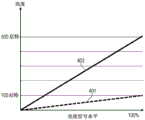
As the process of the luminance correction 321, when the gain amount K of the backlight 208 is increased, the luminance of the input image in all gradations is increased. Fig. 4 shows a state in which the luminance 401 of the input image is raised in all gradations to the luminance as denoted by reference numeral 402. In fig. 4, a relation 401 between the luminance signal level and the luminance before the luminance correction processing is represented by a broken line, and a relation 402 between the luminance signal level and the luminance after the processing is represented by a solid line. Further, for convenience, each of the relationships 401 and 402 is drawn using straight lines; however, it may be a curve such as an exponential function.
In the input image, since the message on the high luminance signal side is compressed, it is desirable to restore the luminance on the high luminance side. In the process of the luminance correction 321, basically, only the gain amount K of the backlight 208 is improved. Thus, as shown in fig. 4, the luminance can be increased almost uniformly from a low luminance region to a high luminance region only using simple linear scaling. However, when the conversion of the luminance dynamic range of the image is performed on the content generator side, it is inferred that the processing of greatly compressing the dynamic range in the high luminance region while maintaining the information in the low luminance region is performed. Therefore, in the subsequent processing of the luminance signal correction 322, the signal curve is optimized with respect to the degraded gradation and the undegraded gradation. The process of the luminance signal correction 322 may be performed in any one of color spaces of YCC, RGB, and HSV.
Specifically, in the luminance signal correction 322, signal processing that degrades the luminance signal is performed on the low luminance side and the intermediate luminance side according to the degree of luminance correction (according to the gain amount of the backlight 208). Fig. 5 shows a state in which the luminance 501 of the input image after luminance correction is corrected to the luminance as indicated by reference numeral 502 due to luminance signal correction.
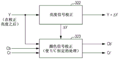
As shown in fig. 5, for example, there is a case where the color tone changes when the signal curve optimization using the luminance signal is used. When it is necessary to completely correct the change in hue, or to some extent, in the subsequent color signal correction 323, when the change in hue is associated with the correction of the luminance signal, the original hue is maintained by performing reverse correction on the change. For example, in the color signal correction 323, the chrominance signal is corrected so that the ratio of the luminance signal to the chrominance signal becomes constant before and after the correction of the luminance signal.
In fig. 6, as the color signal correction 323, a functional configuration in which the chrominance signal is corrected so that the ratio of the luminance signal to the chrominance signal becomes constant before and after the luminance signal is corrected is schematically shown.
In the luminance signal correction 322, the luminance signal Y after the luminance correction 321 is performed due to the gain improvement of the backlight 208 or the like is input, and the luminance signal Y + △ Y is output.
Further, in the color signal correction 323, by inputting the luminance signal Y, the chrominance signals Cb and Cr, and the luminance signal correction △ Y, the input chrominance signals Cb and Cr are corrected so that the ratio of the luminance signal Y to the chrominance signal C becomes constant, specifically, according to the following expressions (1) and (2), the input chrominance signals Cb and Cr are corrected so as to output the chrominance signals Cb 'and Cr'.
[ mathematical formula 1]
Cb′=Cb×(1+ΔY/Y)…(1)
[ mathematical formula 2]
Cr′=Cr×(1+ΔY/Y)…(2)
The functional configuration shown in fig. 6 is an example for performing luminance signal correction and color signal correction in the YCC space. An example of a functional configuration for performing luminance signal correction and color signal correction in the RGB space is shown in fig. 18.
In the luminance signal correction 322, the process of optimizing the signal curve of the luminance signal is performed after the luminance signal Y is calculated from the RGB image signal according to the following expression (3), as described with reference to fig. 5, and the luminance signal Y' after correction is output.
[ mathematical formula 3]
Y=aR+bG+cB…(3)
Further, in the color signal correction 323, the correction coefficient w is multiplied by each color component of RGB by the luminance signal Y' based on the correction after the correctionr、wg、wbColor signal correction is performed.
In this way, by converting an image compressed into a low dynamic range or a standard dynamic range into a high dynamic range as if the image in the high dynamic range, luminance almost close to a real space can be achieved. Further, even in the case where the content originally generated in the low dynamic range or the standard dynamic range is converted into the high dynamic range image, natural high luminance signal information can be expressed by performing the luminance signal correction processing and the color signal correction processing shown in fig. 3, 6, and 18.
Partial drive and thrust
The dynamic range can be further improved by combining the partial driving and pushing technology with a technology of achieving luminance in near real space by restoring high luminance signal information of an image. The partial driving is a technique of controlling an illumination position of a backlight, and can improve luminance contrast by brightly illuminating a backlight corresponding to an area having a high signal level, and on the other hand, by dimly illuminating a backlight corresponding to an area having a low signal level (for example, see PTL 3). Further, the power suppressed at the dark portion is emitted intensively by allocating the power to the area having the high signal level, for example, higher contrast can be performed by performing luminance boost of luminance increase when white display is partially performed (in a state where the total output power of the backlight is constant) (for example, see PTL 4).
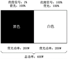
For simplicity and clarity of description, description will be made with reference to fig. 7 to 9 by illustrating an input image in which the left half is a black region having a luminance level of 1%, and the right half is a white region having a luminance level of 100%.
In the example shown in fig. 7, in the entire screen, the gain of the backlight 208 is set to 100%, the luminance signal level in the left half of the liquid crystal display panel 207 is set to 1%, and the luminance signal level in the right half is set to 100%, thereby drawing an image. Further, the output power when the backlight 208 lights the entire screen at 100% is set to 400W at maximum.
In the example shown in fig. 8, in order to draw an image with the same luminance as in fig. 7 (the left half is a black area having a luminance level of 1%, and the right half is a white area having a luminance level of 100%), the power of the backlight 208 is reduced by increasing the luminance signal. By increasing the luminance signal level of the left half of the liquid crystal display panel 207 to 100%, the gain of the backlight of the left half is reduced to 1%. On the other hand, the luminance signal level of the right half is 100%, and the gain of the backlight of the right half is still 100%. When the power of the left half of the backlight 208 becomes 1%, the total power becomes about 200W.
The power of the backlight 208 may be a maximum of 400W or less in total. Thus, as shown in fig. 8, the remaining power obtained by saving power in the left half of the backlight 208 may be used in the right half. In the example shown in fig. 9, the luminance signal level in the left half of the liquid crystal display panel 207 is set to 100%, and the gain of the backlight in the left half is set to 1%. On the other hand, even if the luminance signal level in the right half is 100%, the gain of the backlight can be raised to 200%. In this way, the high brightness dynamic range is increased by a factor of two. Further, the power in the entire backlight 208 may be made not to exceed a maximum power of 400W.
Industrial applicability
The technology disclosed in the present disclosure has been described in detail so far with reference to specific embodiments. However, it is apparent that those skilled in the art may make modifications or substitutions to the embodiments without departing from the scope of the technology disclosed in the present disclosure.
According to the technique disclosed in the present disclosure, without definition information of knee compression, an image subjected to knee compression to be within a low dynamic range or a standard luminance dynamic range can be converted into an image having a high dynamic range close to luminance in a real space. Further, the technique disclosed in the present disclosure can also be applied to a case where content originally generated in a low dynamic range or a standard luminance dynamic range is converted into a high dynamic range image, and natural high luminance signal information can be expressed.
The technique disclosed in the present disclosure is applicable to various devices capable of displaying or outputting HDR images, for example, monitor displays used in information devices such as television receivers, personal computers, and the like, and multifunction terminals such as game machines, projectors, printers, smart phones, and tablet computers.
Further, in the technique disclosed in the present disclosure, the luminance can be made close to the luminance in the real space by restoring the compressed high luminance signal information of the input image, applying to both the still image and the moving image.
In brief, the technology disclosed in the present disclosure has been described in the form of examples, and the description of the present disclosure should not be construed restrictively. To determine the scope of the technology disclosed in this disclosure, the claims should be considered.
The present technology can also be configured as follows.
(1) An image processing apparatus comprising:
and a processing device which determines a degree of degradation of high luminance signal information of the input image, and obtains a luminance signal curve based on the degree of degradation.
(2) The apparatus according to (1) above,
wherein the degree of degradation is determined based on a luminance signal level of the input image.
(3) The apparatus according to (1) or (2),
wherein the processing device controls the brightness of the individual light emitting units in accordance with the brightness signal curve.
(4) The apparatus according to any one of (1) to (3),
wherein the brightness is controlled according to all gray scales.
(5) The apparatus according to any one of (1) to (4),
wherein the brightness is controlled according to all the grays.
(6) The apparatus according to any one of (1) to (5),
wherein at least one of the light emitting units is a light emitting diode.
(7) The apparatus according to any one of (1) to (6),
wherein the processing device controls the power of the backlight of the display device according to the luminance signal curve.
(8) The apparatus according to any one of (1) to (7),
wherein the power of the individual light emitting units of the backlight is controlled by a portion in which the power of a first light emitting unit of the light emitting units is reduced by a first amount of power and the power of a second light emitting unit of the light emitting units is increased by the first amount of power according to the luminance signal curve.
(9) The apparatus according to any one of (1) to (8),
wherein the power of the second light emitting unit is increased by a portion of the first power amount such that the power of the second light emitting unit is greater than the power of each of the light emitting units set when the backlight lights the screen 100% according to the brightness signal level set to 100%.
(10) The apparatus according to any one of (1) to (9),
wherein the processing device controls the chrominance signal according to the luminance signal curve.
(11) The apparatus according to any one of (1) to (10),
wherein the chrominance signal is determined using a luminance signal correction value, which coincides with the luminance signal curve.
(12) The apparatus according to any one of (1) to (11),
wherein the chrominance signals are controlled such that a ratio of the luminance signal to the chrominance signals according to the luminance signal curve is the same as a ratio of the luminance signal representing the luminance of the input image and the chrominance signals representing the hue of the input image.
(13) The apparatus according to any one of (1) to (12),
wherein the chrominance signal is controlled to maintain an initial tone of the input image.
(14) An image processing method comprising:
a degree of degradation of high luminance signal information of an input image is determined by a processing device and a luminance signal curve is obtained by the processing device based on the degree of degradation.
(15) A non-transitory storage medium on which a program for performing image processing is recorded, the program comprising:
a degree of degradation of high luminance signal information of an input image is determined, and a luminance signal curve is obtained based on the degree of degradation.
(16) A display device, comprising:
a processing device that determines a degree of degradation of high luminance signal information of an input image and obtains a luminance signal curve based on the degree of degradation; and
display device comprising a backlight constituted by a plurality of light emitting units, wherein the processing device controls the power of individual light emitting units in accordance with a luminance signal profile.
(17) The display device according to (16),
wherein the processing device controls the brightness of the individual light emitting units in accordance with the brightness signal curve.
(18) The display device according to (16) or (17),
wherein the brightness is controlled according to the gray scale.
(19) The display device according to any one of (16) to (18), wherein the degree of degradation is determined based on a luminance signal level of the input image.
(20) The display device according to any one of (16) to (19), wherein the light emitting unit includes a light emitting diode.
Further, the following configuration in the technique disclosed in the present disclosure may also be employed.
(1) An image processing apparatus comprising:
a determination unit that determines a degree of degradation of high luminance signal information of an input image; and
an adjusting unit that adjusts the input image based on the determination result of the usage determining unit.
(2) The image processing apparatus described in (1), wherein the adjusting unit includes: a luminance correcting unit that corrects luminance based on a determination result of the usage determining unit; a luminance signal correction unit correcting a luminance signal according to the gradation; and a color signal correction unit that corrects a change in hue, the change in hue being associated with the correction of the luminance signal.
(3) The image processing apparatus described in (2), wherein the luminance correcting unit increases the luminance in all the gradations in accordance with the degree of degradation of the high-luminance signal information determined by the determining unit.
(4) The image processing apparatus described in (2), wherein the luminance signal correction unit optimizes the signal curve with respect to the degraded gradation and the non-degraded gradation.
(5) The image processing apparatus described in (2), wherein, when the hue changes in association with the correction of the luminance signal performed using the luminance signal correction unit, the color signal correction unit maintains the initial hue by performing inverse correction for the change.
(6) The image processing apparatus according to (2), wherein the color signal correction unit corrects the chrominance signal so that a ratio of the luminance signal to the chrominance signal becomes constant before and after the luminance signal is corrected. (7) The image processing apparatus described in (1), wherein the determination unit determines the degree of degradation of the high luminance signal information thereof based on the luminance signal level of the input image.
(8) The image processing apparatus described in (1), wherein the determination unit determines the degree of degradation of the high luminance signal information based on at least one of a maximum luminance signal level in the input image, an amount in the vicinity of a maximum luminance signal level value in the input image, an average value of luminance signals in the input image, and an amount in the vicinity of a black level value of the input image.
(9) An image processing method comprising:
determining a degradation degree of high luminance signal information of an input image; and
the input image is adjusted based on the determination result in the determination.
(10) An image display apparatus comprising:
a determination unit that determines a degree of degradation of high luminance signal information of an input image;
an adjusting unit that adjusts the input image based on a determination result of the usage determining unit; and
and a display unit displaying the adjusted image.
REFERENCE SIGNS LIST
100 image display device
101 antenna
102 tuner
103 digital demodulation unit
104 digital decoder
105 display unit
111 media reproduction unit
121 communication unit
131 HDMI (registered trademark) interface unit
201 input terminal
202 video decoder
203 control signal generating unit
204 video encoder
205 data driver
206 gate driver
207 liquid crystal display panel
208 backlight
209 backlight driving control unit
210 power supply
Claims (17)
1. An image processing apparatus comprising:
a processing device that determines a degree of degradation of high luminance signal information of an input image and obtains a luminance signal curve based on the degree of degradation,
wherein the input image is a predetermined dynamic range image derived from a high dynamic range image whose dynamic range is higher than that of the predetermined dynamic range image, and a high luminance portion of the high dynamic range image is suppressed so that luminance of an image falls within the dynamic range of the predetermined dynamic range image, and
wherein the processing device controls the power of the backlight of the display device according to the luminance signal profile, and
wherein the power of the individual light emitting units of the backlight is controlled by a portion in which the power of a first one of the light emitting units is reduced by a first amount of power and the power of a second one of the light emitting units is increased by the first amount of power, according to the luminance signal curve.
2. The apparatus according to claim 1, wherein the degree of degradation is determined based on a luminance signal level of the input image.
3. The apparatus of claim 1, wherein the processing device controls the brightness of individual light emitting units according to the brightness signal profile.
4. The apparatus of claim 3, wherein the brightness is controlled according to a gray scale.
5. The apparatus of claim 4, wherein the brightness is controlled according to all gray scales.
6. The apparatus of claim 3, wherein at least one of the light emitting units is a light emitting diode.
7. The apparatus of claim 1, wherein the power of the second light emitting unit is increased by the first amount of power such that the power of the second light emitting unit is greater than the power of each of the light emitting units set when the backlight lights up the screen 100% according to the brightness signal level set to 100%.
8. The apparatus of claim 1, wherein the processing device controls chroma signals according to the luma signal curve.
9. The apparatus of claim 8, wherein the chrominance signals are determined using a luminance signal correction value, the luminance signal correction value being based on the luminance signal curve.
10. The apparatus of claim 8, wherein the chrominance signals are controlled such that a ratio of a luminance signal to a chrominance signal according to the luminance signal curve is the same as a ratio of a luminance signal representing luminance of the input image and a chrominance signal representing hue of the input image.
11. The apparatus of claim 8, wherein the chrominance signal is controlled to maintain an initial hue of the input image.
12. An image processing method comprising:
determining, by a processing device, a degree of degradation of high luminance signal information of an input image and obtaining, by the processing device, a luminance signal curve based on the degree of degradation,
wherein the input image is a predetermined dynamic range image derived from a high dynamic range image whose dynamic range is higher than that of the predetermined dynamic range image, and a high luminance portion of the high dynamic range image is suppressed so that luminance of an image falls within the dynamic range of the predetermined dynamic range image, and
wherein the processing device controls the power of the backlight of the display device according to the luminance signal profile, and
wherein the power of the individual light emitting units of the backlight is controlled by a portion in which the power of a first one of the light emitting units is reduced by a first amount of power and the power of a second one of the light emitting units is increased by the first amount of power, according to the luminance signal curve.
13. A display device, comprising:
a processing device that determines a degree of degradation of high luminance signal information of an input image and obtains a luminance signal curve based on the degree of degradation; and
a display device including a backlight configured by a plurality of light emitting units,
wherein the input image is a predetermined dynamic range image derived from a high dynamic range image whose dynamic range is higher than that of the predetermined dynamic range image, and a high luminance portion of the high dynamic range image is suppressed so that luminance of an image falls within the dynamic range of the predetermined dynamic range image, and
wherein the processing device controls the power of the individual light emitting units according to the luminance signal profile, and
wherein the power of the individual light emitting units of the backlight is controlled by a portion in which the power of a first one of the light emitting units is reduced by a first amount of power and the power of a second one of the light emitting units is increased by the first amount of power according to the luminance signal curve.
14. The display apparatus according to claim 13, wherein the processing device controls the luminance of the individual light emitting units according to the luminance signal profile.
15. The display device according to claim 14, wherein the luminance is controlled in accordance with a gray scale.
16. The display device according to claim 13, wherein the degree of degradation is determined based on a luminance signal level of the input image.
17. The display device according to claim 13, wherein the light emitting unit comprises a light emitting diode.
Priority Applications (1)
| Application Number | Priority Date | Filing Date | Title |
|---|---|---|---|
| CN201911203107.5A CN110853564B (en) | 2014-03-05 | 2015-03-02 | Image processing apparatus, image processing method, and display apparatus |
Applications Claiming Priority (5)
| Application Number | Priority Date | Filing Date | Title |
|---|---|---|---|
| JP2014042857 | 2014-03-05 | ||
| JP2014-042857 | 2014-03-05 | ||
| JP2014245564A JP6439418B2 (en) | 2014-03-05 | 2014-12-04 | Image processing apparatus, image processing method, and image display apparatus |
| JP2014-245564 | 2014-12-04 | ||
| PCT/JP2015/001081 WO2015133117A1 (en) | 2014-03-05 | 2015-03-02 | Image processing apparatus, image processing method and image display apparatus |
Related Child Applications (1)
| Application Number | Title | Priority Date | Filing Date |
|---|---|---|---|
| CN201911203107.5A Division CN110853564B (en) | 2014-03-05 | 2015-03-02 | Image processing apparatus, image processing method, and display apparatus |
Publications (2)
| Publication Number | Publication Date |
|---|---|
| CN106062860A CN106062860A (en) | 2016-10-26 |
| CN106062860B true CN106062860B (en) | 2020-03-03 |
Family
ID=52697500
Family Applications (2)
| Application Number | Title | Priority Date | Filing Date |
|---|---|---|---|
| CN201580011090.7A Active CN106062860B (en) | 2014-03-05 | 2015-03-02 | Image processing apparatus, image processing method, and image display apparatus |
| CN201911203107.5A Active CN110853564B (en) | 2014-03-05 | 2015-03-02 | Image processing apparatus, image processing method, and display apparatus |
Family Applications After (1)
| Application Number | Title | Priority Date | Filing Date |
|---|---|---|---|
| CN201911203107.5A Active CN110853564B (en) | 2014-03-05 | 2015-03-02 | Image processing apparatus, image processing method, and display apparatus |
Country Status (5)
| Country | Link |
|---|---|
| US (1) | US20160372057A1 (en) |
| EP (1) | EP3114644A1 (en) |
| JP (1) | JP6439418B2 (en) |
| CN (2) | CN106062860B (en) |
| WO (1) | WO2015133117A1 (en) |
Families Citing this family (12)
| Publication number | Priority date | Publication date | Assignee | Title |
|---|---|---|---|---|
| JP2015170905A (en) * | 2014-03-05 | 2015-09-28 | ソニー株式会社 | Image processor, image processing method and image display device |
| EP3139342A1 (en) * | 2015-09-02 | 2017-03-08 | Thomson Licensing | Methods, systems and apparatus for over-exposure correction |
| GB2549521A (en) * | 2016-04-21 | 2017-10-25 | British Broadcasting Corp | Method and apparatus for conversion of dynamic range of video signals |
| JP2019522424A (en) * | 2016-06-28 | 2019-08-08 | インターデジタル ヴイシー ホールディングス, インコーポレイテッド | Method and apparatus for transmitting zone backlight metadata for high dynamic range |
| JP6779695B2 (en) * | 2016-07-28 | 2020-11-04 | キヤノン株式会社 | Image processing device and its control method, display device |
| US10201049B1 (en) * | 2017-08-03 | 2019-02-05 | Apple Inc. | Local display backlighting systems and methods |
| KR102516828B1 (en) * | 2017-12-28 | 2023-03-31 | 삼성전자주식회사 | Image processing apparatus, mage processing method and multi-screen display |
| KR102463965B1 (en) * | 2018-01-04 | 2022-11-08 | 삼성디스플레이 주식회사 | Organic light emitting display device and driving method of the same |
| KR20220019682A (en) | 2019-06-13 | 2022-02-17 | 소니그룹주식회사 | Image processing apparatus and image processing method, display apparatus equipped with artificial intelligence function, and method of generating a trained neural network model |
| CN110400544A (en) * | 2019-08-05 | 2019-11-01 | 业成科技(成都)有限公司 | Signal processing method and display device |
| JP7369574B2 (en) | 2019-09-19 | 2023-10-26 | 日本放送協会 | Video conversion device and its program |
| CN114222187B (en) * | 2021-08-12 | 2023-08-29 | 荣耀终端有限公司 | Video editing method and electronic equipment |
Family Cites Families (36)
| Publication number | Priority date | Publication date | Assignee | Title |
|---|---|---|---|---|
| JP2001034255A (en) * | 1999-07-23 | 2001-02-09 | Fuji Photo Film Co Ltd | Picture display method and device |
| JP3430998B2 (en) * | 1999-11-08 | 2003-07-28 | 松下電器産業株式会社 | Image display device and image display method |
| JP3487278B2 (en) * | 2000-10-02 | 2004-01-13 | 松下電器産業株式会社 | Liquid crystal display |
| JP2002152771A (en) * | 2000-11-10 | 2002-05-24 | Matsushita Electric Ind Co Ltd | Video signal processing apparatus |
| JP3877624B2 (en) * | 2002-03-29 | 2007-02-07 | 東北パイオニア株式会社 | Display device aging method and electronic device |
| JP2004252620A (en) * | 2003-02-19 | 2004-09-09 | Sony Corp | Image processing device and method, and program |
| US8265378B2 (en) * | 2004-04-15 | 2012-09-11 | Dolby Laboratories Licensing Corporation | Methods and systems for converting images from low dynamic to high dynamic range |
| US8248392B2 (en) * | 2004-08-13 | 2012-08-21 | Semiconductor Energy Laboratory Co., Ltd. | Light emitting device using light emitting element and driving method of light emitting element, and lighting apparatus |
| US7715649B2 (en) * | 2005-02-14 | 2010-05-11 | Fujifilm Corporation | Generation and adjustment of a luminance correction curve to prevent saturation of the image during contrast enhancement |
| JP5130634B2 (en) * | 2006-03-08 | 2013-01-30 | ソニー株式会社 | Self-luminous display device, electronic device, burn-in correction device, and program |
| JP2007241193A (en) * | 2006-03-13 | 2007-09-20 | Seiko Epson Corp | Image display controller, projector and control method thereof |
| EP1998571A1 (en) * | 2006-03-20 | 2008-12-03 | Sony Corporation | Image signal processing device and image signal processing method |
| CA2556961A1 (en) * | 2006-08-15 | 2008-02-15 | Ignis Innovation Inc. | Oled compensation technique based on oled capacitance |
| JP5332172B2 (en) * | 2006-11-10 | 2013-11-06 | セイコーエプソン株式会社 | Image display control device |
| JP2009267475A (en) * | 2008-04-22 | 2009-11-12 | Sony Corp | Display control device and method, and program |
| JP2010020241A (en) * | 2008-07-14 | 2010-01-28 | Sony Corp | Display apparatus, method of driving display apparatus, drive-use integrated circuit, driving method employed by drive-use integrated circuit, and signal processing method |
| US8339475B2 (en) * | 2008-12-19 | 2012-12-25 | Qualcomm Incorporated | High dynamic range image combining |
| CN102341826B (en) * | 2009-03-06 | 2014-03-19 | 皇家飞利浦电子股份有限公司 | Method for converting input image data into output image data |
| CN102422322B (en) * | 2009-05-11 | 2015-01-21 | 杜比实验室特许公司 | Light detection, color appearance models, and modifying dynamic range for image display |
| CN102667581B (en) * | 2009-09-22 | 2014-12-17 | 株式会社东芝 | Image processing device and image display device |
| EP2485211A4 (en) * | 2009-09-29 | 2012-08-29 | Panasonic Corp | Display device and display method |
| KR101034755B1 (en) * | 2009-11-12 | 2011-05-17 | 삼성모바일디스플레이주식회사 | Luminance correction system and luminance correction method using the same |
| JP5236622B2 (en) * | 2009-12-17 | 2013-07-17 | シャープ株式会社 | Display device |
| US8629913B2 (en) * | 2010-09-30 | 2014-01-14 | Apple Inc. | Overflow control techniques for image signal processing |
| US9275605B2 (en) * | 2010-11-23 | 2016-03-01 | Dolby Laboratories Licensing Corporation | Content metadata enhancement of high dynamic range images |
| PL3595281T3 (en) * | 2011-05-27 | 2022-06-06 | Dolby Laboratories Licensing Corporation | Scalable systems for controlling color management comprising varying levels of metadata |
| JP2013033088A (en) * | 2011-08-01 | 2013-02-14 | Mitsubishi Electric Corp | Light-emitting device, display device, control device, control method and control program |
| JP5270730B2 (en) * | 2011-08-03 | 2013-08-21 | シャープ株式会社 | Video display device |
| GB2493931A (en) * | 2011-08-22 | 2013-02-27 | Apical Ltd | Display Device Brightness and Dynamic Range Compression Control |
| PE20141864A1 (en) * | 2011-09-27 | 2014-12-12 | Koninkl Philips Nv | APPARATUS AND METHOD FOR TRANSFORMING THE DYNAMIC RANGE OF IMAGES |
| JP5924147B2 (en) * | 2012-06-14 | 2016-05-25 | ソニー株式会社 | Display device, image processing device, and display method |
| EP2836983B1 (en) * | 2012-10-08 | 2017-07-12 | Koninklijke Philips N.V. | Luminance changing image processing with color constraints |
| CN104956670B (en) * | 2013-01-25 | 2017-09-08 | 杜比实验室特许公司 | Light modulation based on global display management |
| JP5911518B2 (en) * | 2014-01-29 | 2016-04-27 | キヤノン株式会社 | Display device, display device control method, and program |
| JP5897159B2 (en) * | 2014-02-25 | 2016-03-30 | キヤノン株式会社 | Display device and control method thereof |
| US10623805B2 (en) * | 2014-11-17 | 2020-04-14 | Sony Corporation | Sending device, method of sending high dynamic range image data, receiving device, and method of receiving high dynamic range image data |
-
2014
- 2014-12-04 JP JP2014245564A patent/JP6439418B2/en active Active
-
2015
- 2015-03-02 CN CN201580011090.7A patent/CN106062860B/en active Active
- 2015-03-02 CN CN201911203107.5A patent/CN110853564B/en active Active
- 2015-03-02 WO PCT/JP2015/001081 patent/WO2015133117A1/en active Application Filing
- 2015-03-02 US US15/121,444 patent/US20160372057A1/en not_active Abandoned
- 2015-03-02 EP EP15711317.6A patent/EP3114644A1/en not_active Ceased
Also Published As
| Publication number | Publication date |
|---|---|
| US20160372057A1 (en) | 2016-12-22 |
| EP3114644A1 (en) | 2017-01-11 |
| CN110853564B (en) | 2023-06-23 |
| CN110853564A (en) | 2020-02-28 |
| JP6439418B2 (en) | 2018-12-19 |
| JP2015181217A (en) | 2015-10-15 |
| WO2015133117A1 (en) | 2015-09-11 |
| CN106062860A (en) | 2016-10-26 |
Similar Documents
| Publication | Publication Date | Title |
|---|---|---|
| CN106062860B (en) | Image processing apparatus, image processing method, and image display apparatus | |
| CN107492334B (en) | Electronic display method, system and non-transitory program storage device | |
| US7453475B2 (en) | Optical display device, program for controlling the optical display device, and method of controlling the optical display device | |
| JP5595516B2 (en) | Method and system for backlight control using statistical attributes of image data blocks | |
| US11195483B2 (en) | Global light compensation in a variety of displays | |
| US8358293B2 (en) | Method for driving light source blocks, driving unit for performing the method and display apparatus having the driving unit | |
| TWI549112B (en) | Display device and electronic machine having the same, and method for driving display device | |
| WO2009096068A1 (en) | Image display device and image display method | |
| US9990878B2 (en) | Data clipping method using red, green, blue and white data, and display device using the same | |
| US20120169792A1 (en) | Display device and display method | |
| US20100013866A1 (en) | Light source device and liquid crystal display unit | |
| JP2008102379A (en) | Image display device and method | |
| JP2007034251A (en) | Display apparatus and display method | |
| JP2008203292A (en) | Image display device and image display method | |
| KR20070036720A (en) | Display image correcting device, image display device, and display image correcting method | |
| JP2012118313A (en) | Luminance controller, display device with luminance controller, and illuminating device | |
| JP2007322942A (en) | Backlight driving device, display device, and backlight driving method | |
| JP2006308631A (en) | Device, method and program for image display, and recording medium with image display program recorded | |
| US9047825B2 (en) | Display device and display method | |
| KR20180063608A (en) | Method for controlling backlight unit accroding to screen mode and display device performing the same | |
| US20110007100A1 (en) | Backlight controller and liquid crystal display device | |
| Hatchett et al. | Displaying detail in bright environments: A 10,000 nit display and its evaluation | |
| Seetzen | High dynamic range display andprojection systems | |
| JP2015082021A (en) | Display device, driving method of display device, and electronic apparatus | |
| Kim | Optically adjustable display color gamut in time-sequential displays using LED/Laser light sources |
Legal Events
| Date | Code | Title | Description |
|---|---|---|---|
| C06 | Publication | ||
| PB01 | Publication | ||
| SE01 | Entry into force of request for substantive examination | ||
| SE01 | Entry into force of request for substantive examination | ||
| GR01 | Patent grant | ||
| GR01 | Patent grant |