JP6779695B2 - Image processing device and its control method, display device - Google Patents
Image processing device and its control method, display device Download PDFInfo
- Publication number
- JP6779695B2 JP6779695B2 JP2016148940A JP2016148940A JP6779695B2 JP 6779695 B2 JP6779695 B2 JP 6779695B2 JP 2016148940 A JP2016148940 A JP 2016148940A JP 2016148940 A JP2016148940 A JP 2016148940A JP 6779695 B2 JP6779695 B2 JP 6779695B2
- Authority
- JP
- Japan
- Prior art keywords
- image
- brightness
- display
- output
- range
- Prior art date
- Legal status (The legal status is an assumption and is not a legal conclusion. Google has not performed a legal analysis and makes no representation as to the accuracy of the status listed.)
- Active
Links
- 238000000034 method Methods 0.000 title claims description 44
- 230000008569 process Effects 0.000 claims description 38
- 238000006243 chemical reaction Methods 0.000 description 50
- 238000010586 diagram Methods 0.000 description 23
- 230000007423 decrease Effects 0.000 description 20
- 238000005259 measurement Methods 0.000 description 19
- 230000008859 change Effects 0.000 description 9
- 230000006866 deterioration Effects 0.000 description 7
- 239000004973 liquid crystal related substance Substances 0.000 description 4
- 230000001915 proofreading effect Effects 0.000 description 3
- 238000007906 compression Methods 0.000 description 2
- 230000003287 optical effect Effects 0.000 description 2
- 230000004044 response Effects 0.000 description 2
- 239000003086 colorant Substances 0.000 description 1
- 230000006835 compression Effects 0.000 description 1
- 238000001514 detection method Methods 0.000 description 1
- 230000000694 effects Effects 0.000 description 1
- 238000003384 imaging method Methods 0.000 description 1
- 230000006872 improvement Effects 0.000 description 1
- 239000011159 matrix material Substances 0.000 description 1
- 230000009467 reduction Effects 0.000 description 1
- 229920006395 saturated elastomer Polymers 0.000 description 1
- 239000004065 semiconductor Substances 0.000 description 1
- 230000000007 visual effect Effects 0.000 description 1
Images


Classifications
-
- G06T5/92—
-
- G—PHYSICS
- G09—EDUCATION; CRYPTOGRAPHY; DISPLAY; ADVERTISING; SEALS
- G09G—ARRANGEMENTS OR CIRCUITS FOR CONTROL OF INDICATING DEVICES USING STATIC MEANS TO PRESENT VARIABLE INFORMATION
- G09G5/00—Control arrangements or circuits for visual indicators common to cathode-ray tube indicators and other visual indicators
- G09G5/10—Intensity circuits
-
- G06T3/04—
-
- G06T5/90—
-
- G—PHYSICS
- G09—EDUCATION; CRYPTOGRAPHY; DISPLAY; ADVERTISING; SEALS
- G09G—ARRANGEMENTS OR CIRCUITS FOR CONTROL OF INDICATING DEVICES USING STATIC MEANS TO PRESENT VARIABLE INFORMATION
- G09G3/00—Control arrangements or circuits, of interest only in connection with visual indicators other than cathode-ray tubes
- G09G3/20—Control arrangements or circuits, of interest only in connection with visual indicators other than cathode-ray tubes for presentation of an assembly of a number of characters, e.g. a page, by composing the assembly by combination of individual elements arranged in a matrix no fixed position being assigned to or needed to be assigned to the individual characters or partial characters
- G09G3/34—Control arrangements or circuits, of interest only in connection with visual indicators other than cathode-ray tubes for presentation of an assembly of a number of characters, e.g. a page, by composing the assembly by combination of individual elements arranged in a matrix no fixed position being assigned to or needed to be assigned to the individual characters or partial characters by control of light from an independent source
- G09G3/36—Control arrangements or circuits, of interest only in connection with visual indicators other than cathode-ray tubes for presentation of an assembly of a number of characters, e.g. a page, by composing the assembly by combination of individual elements arranged in a matrix no fixed position being assigned to or needed to be assigned to the individual characters or partial characters by control of light from an independent source using liquid crystals
-
- G—PHYSICS
- G06—COMPUTING; CALCULATING OR COUNTING
- G06T—IMAGE DATA PROCESSING OR GENERATION, IN GENERAL
- G06T2207/00—Indexing scheme for image analysis or image enhancement
- G06T2207/20—Special algorithmic details
- G06T2207/20172—Image enhancement details
- G06T2207/20208—High dynamic range [HDR] image processing
-
- G—PHYSICS
- G09—EDUCATION; CRYPTOGRAPHY; DISPLAY; ADVERTISING; SEALS
- G09G—ARRANGEMENTS OR CIRCUITS FOR CONTROL OF INDICATING DEVICES USING STATIC MEANS TO PRESENT VARIABLE INFORMATION
- G09G2320/00—Control of display operating conditions
- G09G2320/02—Improving the quality of display appearance
- G09G2320/0271—Adjustment of the gradation levels within the range of the gradation scale, e.g. by redistribution or clipping
- G09G2320/0276—Adjustment of the gradation levels within the range of the gradation scale, e.g. by redistribution or clipping for the purpose of adaptation to the characteristics of a display device, i.e. gamma correction
-
- G—PHYSICS
- G09—EDUCATION; CRYPTOGRAPHY; DISPLAY; ADVERTISING; SEALS
- G09G—ARRANGEMENTS OR CIRCUITS FOR CONTROL OF INDICATING DEVICES USING STATIC MEANS TO PRESENT VARIABLE INFORMATION
- G09G2320/00—Control of display operating conditions
- G09G2320/06—Adjustment of display parameters
- G09G2320/0693—Calibration of display systems
-
- G—PHYSICS
- G09—EDUCATION; CRYPTOGRAPHY; DISPLAY; ADVERTISING; SEALS
- G09G—ARRANGEMENTS OR CIRCUITS FOR CONTROL OF INDICATING DEVICES USING STATIC MEANS TO PRESENT VARIABLE INFORMATION
- G09G2320/00—Control of display operating conditions
- G09G2320/08—Arrangements within a display terminal for setting, manually or automatically, display parameters of the display terminal
-
- G—PHYSICS
- G09—EDUCATION; CRYPTOGRAPHY; DISPLAY; ADVERTISING; SEALS
- G09G—ARRANGEMENTS OR CIRCUITS FOR CONTROL OF INDICATING DEVICES USING STATIC MEANS TO PRESENT VARIABLE INFORMATION
- G09G2340/00—Aspects of display data processing
- G09G2340/04—Changes in size, position or resolution of an image
- G09G2340/0407—Resolution change, inclusive of the use of different resolutions for different screen areas
- G09G2340/0428—Gradation resolution change
-
- G—PHYSICS
- G09—EDUCATION; CRYPTOGRAPHY; DISPLAY; ADVERTISING; SEALS
- G09G—ARRANGEMENTS OR CIRCUITS FOR CONTROL OF INDICATING DEVICES USING STATIC MEANS TO PRESENT VARIABLE INFORMATION
- G09G2360/00—Aspects of the architecture of display systems
- G09G2360/14—Detecting light within display terminals, e.g. using a single or a plurality of photosensors
- G09G2360/145—Detecting light within display terminals, e.g. using a single or a plurality of photosensors the light originating from the display screen
-
- G—PHYSICS
- G09—EDUCATION; CRYPTOGRAPHY; DISPLAY; ADVERTISING; SEALS
- G09G—ARRANGEMENTS OR CIRCUITS FOR CONTROL OF INDICATING DEVICES USING STATIC MEANS TO PRESENT VARIABLE INFORMATION
- G09G2360/00—Aspects of the architecture of display systems
- G09G2360/16—Calculation or use of calculated indices related to luminance levels in display data
Description
本発明は、画像処理装置及びその制御方法、表示装置に関する。 The present invention relates to an image processing device, a control method thereof, and a display device.
近年、撮像装置の受光性能の向上に伴い、一般的なビデオガンマとして用いられているBT.709よりも対応する輝度の範囲(ダイナミックレンジ)が広い画像が生成されるようになってきている。このような、広いダイナミックレンジを、High Dynamic Range(HDR)と記載し、HDRに対応した画像をHDR画像と記載する。 In recent years, with the improvement of the light receiving performance of an imaging device, BT. Images having a corresponding brightness range (dynamic range) wider than that of 709 are being generated. Such a wide dynamic range is referred to as a High Dynamic Range (HDR), and an image corresponding to HDR is referred to as an HDR image.
一方で、表示装置でHDR画像を視聴する場合、ユーザの好みに応じて、入力されたHDR画像のうち、指定された輝度に忠実に表示する範囲(表示レンジ)を設定して表示する場合がある。この様な場合、HDR画像のダイナミックレンジを表示レンジに狭める画像処理(圧縮処理)をHDR画像に施して、表示画像を生成することがある。 On the other hand, when viewing an HDR image on a display device, the range (display range) of the input HDR image that is faithfully displayed to the specified brightness may be set and displayed according to the user's preference. is there. In such a case, the HDR image may be subjected to image processing (compression processing) that narrows the dynamic range of the HDR image to the display range to generate a display image.
圧縮処理に関する従来技術は、例えば、特許文献1に開示されている。特許文献1に開示の技術では、所定の輝度以下の画素の輝度は維持しつつ、所定の輝度以上の画素が表示レンジの上限値で飽和させて表示されるように、表示画像が生成される。 The prior art relating to the compression process is disclosed in, for example, Patent Document 1. In the technique disclosed in Patent Document 1, a display image is generated so that pixels having a predetermined brightness or more are saturated at the upper limit of the display range while maintaining the brightness of pixels having a predetermined brightness or less. ..
特許文献1に開示された技術で生成した表示画像に基づいて、表示装置で画像を表示した場合、表示画像において最大の階調値が指定された領域は、表示装置の表示輝度の最大値で表示される。 When an image is displayed on a display device based on a display image generated by the technique disclosed in Patent Document 1, the region in which the maximum gradation value is specified in the display image is the maximum value of the display brightness of the display device. Is displayed.
しかしながら、表示装置が表示可能な最大の表示輝度は、例えば、表示装置が液晶ディスプレイである場合には、バックライトの光源の経年劣化等により、低下することがあった。表示装置が表示可能な最大の表示輝度が、ユーザが指定した表示レンジの最大値を下回る場合、ユーザが意図した表示輝度で、画像を表示することができない場合があった。 However, the maximum display brightness that the display device can display may decrease due to deterioration of the light source of the backlight over time, for example, when the display device is a liquid crystal display. When the maximum display brightness that can be displayed by the display device is less than the maximum value of the display range specified by the user, the image may not be displayed at the display brightness intended by the user.
本発明は、表示装置が表示可能な最大の表示輝度が変化する場合に、入力画像のうち、ユーザが指定した表示レンジに対応する領域の表示輝度が変化することを抑制することが可能な画像処理装置を提供することを目的とする。 According to the present invention, when the maximum display brightness that can be displayed by the display device changes, it is possible to suppress the change in the display brightness of the region corresponding to the display range specified by the user among the input images. It is an object of the present invention to provide a processing apparatus.
本発明の画像処理装置は、表示手段に表示される画像の輝度を測定するための測定手段から測定値を取得する第1取得手段と、前記測定値に基づいて出力ダイナミックレンジを設定する設定手段と、前記出力ダイナミックレンジに基づいて入力画像の階調値を変換して、出力画像を生成する画像処理手段と、前記出力画像を前記表示手段に出力する出力手段と、を備え、前記画像処理手段は、前記出力ダイナミックレンジの取り得る最大の輝度関連値および前記測定値のうち少なくとも一方を示すグラフィック画像を前記出力画像に合成することを特徴とする。 The image processing apparatus of the present invention includes a first acquisition means for acquiring a measured value from a measuring means for measuring the brightness of an image displayed on the display means, and a setting means for setting an output dynamic range based on the measured value. If, by converting the tone values of the input image based on the output dynamic range, comprising image processing means for generating an output image, and output means for outputting the output image on the display means, wherein the image processing means is characterized that you synthesize a graphic image on the output image indicating at least one of the maximum luminance related value and the measured value which can be taken of the output dynamic range.
本発明の画像処理装置によれば、表示装置が表示可能な最大の表示輝度が変化する場合に、入力画像のうち、ユーザが指定した表示レンジに対応する領域の表示輝度が変化することを抑制することが可能となる。 According to the image processing device of the present invention, when the maximum display brightness that can be displayed by the display device changes, the display brightness of the area corresponding to the display range specified by the user of the input image is suppressed from changing. It becomes possible to do.
(第1の実施例)
以下に、本発明の第1の実施例に係る画像処理装置及びその制御方法について説明する。なお、本発明は、画像処理装置と、画像処理装置が生成した画像を表示するディスプレイとを含む表示装置にも適用可能である。例えば、本発明は、液晶表示装置、有機EL表示装置、プラズマ表示装置、等に適用することができる。また、本実施例では、画像表示装置に入力される画像データ(入力画像データ)が、画像処理装置が備える記憶媒体に記憶された画像データである場合の例を説明するが、入力画像データは撮像装置を用いた撮影によって得られた撮影画像データであってもよい。
(First Example)
The image processing apparatus and the control method thereof according to the first embodiment of the present invention will be described below. The present invention can also be applied to a display device including an image processing device and a display for displaying an image generated by the image processing device. For example, the present invention can be applied to a liquid crystal display device, an organic EL display device, a plasma display device, and the like. Further, in this embodiment, an example in which the image data (input image data) input to the image display device is the image data stored in the storage medium included in the image processing device will be described, but the input image data is It may be photographed image data obtained by photographing with an image pickup apparatus.
図1は、第1の実施例に係る画像処理装置1と測定装置2と表示部3とを示す装置構成図である。図1に示すように、画像処理装置1は、測定装置2と表示部3とに接続可能である。例えば、画像処理装置1は、パーソナルコンピュータ(Personal Computer、PC)であるとする。画像処理装置1は、測定装置2の動作を制御し、かつ、測定装置2が測定した輝度測定値を取得する。また、画像処理装置1は、輝度測定値に基づいて、表示部3に出力する出力画像のダイナミックレンジを決定し、入力画像のダイナミックレンジを変換して、出力画像を生成して、表示部3に出力する。
FIG. 1 is a device configuration diagram showing an image processing device 1, a
測定装置2は、表示部3から照射される光の輝度を測定する光センサを備える測定器である。
The
表示部3は、画像処理装置1が出力した画像データに基づいて、画像を表示するディスプレイである。表示部3は、マトリクス状に配置された複数の画素を有する画面に、取得した画像データに基づく画像を表示する。例えば、表示部3は、液晶パネルとバックライトとを備える液晶表示装置であるとする。なお、画像処理装置1と表示部3とで表示装置を構成してもよい。
The
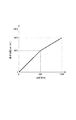
図2は、表示部3に入力される画像の階調値と、表示輝度との関係を示す模式図である。図2は、表示部3の表示特性を示す。表示部3は、階調値に対して線形に、表示輝度が対応する表示特性を有するとする。表示部3は、入力される画像の階調値の取り得る値の最大値に対して、表示可能な最大の表示輝度が対応するとする。
FIG. 2 is a schematic diagram showing the relationship between the gradation value of the image input to the
図2の直線21は、表示部3の表示輝度の最大値が低下する前(輝度低下前)の表示特性を示す。輝度低下前の表示部3は、1000cd/m2までの表示輝度を表示可能であるとする。また、図2の直線22は、表示部3の表示輝度の最大値が低下した場合(輝度低下時)の表示特性を示す。輝度低下時の表示部3の表示輝度の最大値は、800cd/m2まで低下する。「cd/m2」は、輝度の絶対値を示す単位である。表示部3は、階調値に対して、表示輝度が線形に対応する表示特性を有することから、輝度低下時の表示部3の表示特性は、輝度低下前の表示部3の表示特性に比べて、階調値に対する表示輝度が低下する。表示部3の表示特性は、後述する画像処理装置1の記憶部200に記憶されているとする。
The
測定装置2は、画像処理装置1が出力した校正画像に基づいて表示部3が画像を表示した場合に、表示部3から照射される光の輝度を測定する。測定装置2は、測定した輝度を、画像処理装置1に出力する。
The
校正画像は、測定装置2が、表示部3の表示可能な最大の輝度を測定するために用いる画像である。校正画像は、測定装置2が輝度を測定する位置において、表示部3が表示可能な最大の階調値を、所定の大きさ以上で表示する画像である。例えば、表示部3が、赤色(R)、緑色(G)、および青色(B)の各色に対応する副画素を有し、各副画素に対して10ビットデータで階調値が表される画像データに基づいて画像を表示可能であるとする。この場合、校正画像は、各画素の副画素に対して、1023の階調値を指定した画像である。つまり、校正画像は、測定装置2が輝度を測定する表示部3の画面の位置において、全白画像が表示される画像である。
The calibration image is an image used by the
つまり、測定装置2は、校正画像に基づいて画像を表示した表示部3の輝度を測定することにより、表示部3が表示可能な最大の表示輝度を示す表示最大輝度を測定する。
That is, the measuring
画像処理装置1は、校正処理(キャリブレーション)を実行する場合、記憶部200から校正画像を読み出して、表示部3に出力する。例えば、画像処理装置1は、測定装置2の光センサが対向する表示部3の画面の位置(測定位置)に、全白画像が表示されるように予め生成された校正画像を、表示部3に出力するとする。なお、校正画像は、校正処理を実行する際に設定された測定位置に基づいて、生成されるものであってもよい。
When the image processing device 1 executes the calibration process (calibration), the image processing device 1 reads the proofread image from the
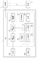
図3は、第1の実施例に係る画像処理装置1の構成の一例を示すブロック図である。図3に示すように、画像処理装置1は、制御部100、記憶部200、および操作部300を有する。
FIG. 3 is a block diagram showing an example of the configuration of the image processing device 1 according to the first embodiment. As shown in FIG. 3, the image processing device 1 has a
制御部100は、記憶部200から取得した入力画像のダイナミックレンジを、測定装置2から取得した輝度測定値に基づいて決定された表示レンジに変換して、出力画像を生成し、表示部3に出力する制御回路基板である。制御部100は、後述する各機能ブロックの全てもしくは一部の処理を実行するためのCentral Processing Unit(CPU)や、Micro Processing Unit(MPU)等の演算処理装置を備える。また、制御部100は、後述する各機能ブロックの一部の処理を実行するための電子回路等のハードウェアを備えていてもよい。また、制御部100の演算処理装置は、記憶部200から読み取ったプログラムを実行することにより、後述の処理を実行する。
The
記憶部200は、制御部100が生成する出力画像のもととなる画像データ、制御部100の演算処理装置が実行するプログラム、およびプログラムの実行に用いるパラメータを記憶する演算処理装置が読取可能な記憶媒体である。例えば、記憶部200は、ハードディスク等の不揮発性の記憶媒体であるとする。記憶部200は、半導体メモリ等の揮発性の記憶媒体を備えていてもよい。また、記憶部200は、測定装置2から取得した検出輝度を記憶する。
The
操作部300は、ユーザが、画像処理装置1に対して、指示を入力するための操作部材である。例えば、操作部300は、キーボードやマウス等の物理的に信号を入力するための入力装置であるとする。また、操作部300は、表示部3に表示されたGuraphical User Interface(GUI)を操作して、ユーザの指示を入力するものであってもよい。例えば、操作部300は、画像処理装置1に対して、キャリブレーションの実行の指示や、表示レンジ設定値の入力が可能であるとする。
The
制御部100は、画像処理部101、入力レンジ取得部102、表示レンジ取得部103、測定輝度取得部104、表示レンジ決定部105、出力部106、および校正制御部107を備える。さらに、画像処理部101は、リニア変換部108とレンジ変換部109とを備える。
The
画像処理部101は、出力画像の対象とするダイナミックレンジが表示レンジ決定部105から取得した表示レンジになるように、入力画像の階調値を変換して、出力画像を生成する。画像処理部101は、画像処理部101は、出力画像を出力部106に出力する。画像処理部101の具体的な処理は、後述する。
The
入力レンジ取得部102は、入力画像のダイナミックレンジ(入力レンジ)を取得する。具体的には、入力レンジは、入力画像が対象とする輝度関連値の範囲である。入力レンジは、入力画像取り得る輝度関連値の範囲とも言える。入力レンジ取得部102は、取得した入力レンジを示す情報を画像処理部101に出力する。
The input
例えば、入力レンジは、入力画像のデータに付加された情報であるとする。この場合、入力レンジ取得部102は、入力画像から、入力レンジを示す情報を分離する処理を実行して入力レンジを取得する。なお、入力画像が、画像処理装置1に接続された撮像装置から入力される撮影画像である場合には、入力レンジ取得部は、撮像装置から、入力レンジを示す情報を取得することができる。
For example, it is assumed that the input range is information added to the data of the input image. In this case, the input
輝度関連値は、輝度に関連した値である。本実施例において、輝度関連値は、反射率であるとする。反射率は、輝度の表現の一形式であり、光が物体で反射する際の光源の輝度と反射光の輝度の比率を示す。環境光下で照明された物体の輝度は0〜100%程度の反射率で表現され、それを超える輝度を有する光源(照明装置、太陽、等)の輝度は100%以上の反射率で表現されることが多い。本実施例では、入力画像データが対象とする反射率が0〜1000%であり、入力画像データの信号レベル(階調値)は10ビットの値(0〜1023)であるものとする。 The brightness-related value is a value related to brightness. In this embodiment, the brightness-related value is the reflectance. Reflectance is a form of expression of luminance, and indicates the ratio of the luminance of a light source to the luminance of reflected light when light is reflected by an object. The brightness of an object illuminated under ambient light is expressed by a reflectance of about 0 to 100%, and the brightness of a light source (lighting device, sun, etc.) having a brightness exceeding that is expressed by a reflectance of 100% or more. Often. In this embodiment, it is assumed that the reflectance of the input image data is 0 to 1000%, and the signal level (gradation value) of the input image data is a 10-bit value (0 to 1023).
なお、輝度関連値は、輝度に関連した値であればよく、反射率に限らない。例えば、輝度関連値は、輝度(輝度値)そのものであってもよいし、撮像装置が有する撮像センサに入射した光の量(光量)であってもよい。また、入力画像データが対象とする反射率の範囲、及び、入力画像データの階調値の範囲は、上述した範囲より狭くても広くてもよい。 The luminance-related value may be any value related to the luminance, and is not limited to the reflectance. For example, the brightness-related value may be the brightness (luminance value) itself, or may be the amount of light (light amount) incident on the image sensor included in the image pickup device. Further, the range of the reflectance of the input image data and the range of the gradation value of the input image data may be narrower or wider than the above-mentioned range.
設定レンジ取得部103は、操作部300を介してユーザが入力した設定レンジを示す情報を取得する。設定レンジは、入力レンジのうち、入力画像に基づく画像が表示部3に表示される場合に、入力画像に指示された輝度関連値に対応する輝度で忠実に表示するダイナミックレンジである。例えば、ユーザが設定レンジとして、0〜1000%を入力したとする。設定レンジ取得部103は、取得した表示レンジを示す情報を画像処理部101に出力する。
The setting
設定レンジ取得部103は、ユーザが設定した動作モードに応じて、設定レンジを取得することも可能である。例えば、BT.709に対応する表示モードが設定された場合には、設定レンジ取得部103は、設定レンジとして0〜100%のダイナミックレンジを取得する。そして、BT.709よりもダイナミックレンジが広い画像データに対応する表示モードが設定された場合には、設定レンジ取得部103は、表示モードに応じて、0〜100%の範囲よりも広い設定レンジを取得する。広いダイナミックレンジ(例えば、BT.709よりも広いダイナミックレンジ)は、「HDR(High Dynamic Range)」と言うことができる。ダイナミックレンジが広い画像データは、「HDR画像データ」と言うことができる。
The setting
測定輝度取得部104は、校正処理を実行することに応じて、測定装置2から表示部3の表示可能な輝度の最大値を示す表示最大輝度を取得する。例えば、表示最大輝度は、800cd/m2(輝度低下時の表示部3の表示輝度の最大値)であるとする。なお、測定輝度取得部104は、校正制御部107から取得した信号に基づいて、測定装置2が輝度測定を実行するように、測定装置2を制御してもよい。
The measurement
表示レンジ決定部105は、設定レンジ取得部103から取得した設定レンジを示す情報と、測定輝度取得部104から取得した表示最大輝度に基づいて、画像処理部101が生成する出力画像のダイナミックレンジ(表示レンジ)を決定する。具体的には、表示レンジ決定部105は、設定レンジと参照レンジとのうち、狭いほうのダイナミックレンジを、表示レンジとする。
The display
図4は、輝度関連値と表示輝度との対応関係を示す輝度関連情報を示す表である。図4において、輝度関連値は、反射率である。輝度関連値と表示輝度との対応関係を示す輝度関連情報は、例えば、テーブルデータとして記憶部200に記憶されているとする。本実施例において、入力画像の反射率と、表示輝度との関係は、線形であるとする。例えば、入力画像の反射率100%は、表示輝度100cd/m2に対応するとする。
FIG. 4 is a table showing luminance-related information showing the correspondence between the luminance-related values and the display luminance. In FIG. 4, the luminance-related value is the reflectance. It is assumed that the luminance-related information indicating the correspondence between the luminance-related value and the display luminance is stored in the
表示レンジ決定部105は、表示最大輝度と、輝度関連情報と、を用いて、表示最大輝度に対応する参照レンジを取得する。図4より、測定輝度取得部104から取得した表示最大輝度(800cd/m2)に対応する参照レンジは、0〜800%である。したがって、この場合、表示レンジ決定部105は、参照レンジ(800%)を、表示レンジとして決定する。表示レンジ決定部105は、表示レンジを示す情報を画像処理部101に出力する。
The display
出力部106は、画像処理部101が出力した出力画像を、表示部3に出力する。出力部106は、表示部3が利用可能なデータの形式に出力画像を変換して出力してもよい。また、後述するように、校正処理実行時に校正制御部107の指示に応じて、記憶部200から読み出した校正画像を表示部3に出力する。
The
校正制御部107は、校正処理を実行するように、測定輝度取得部104と出力部106とを制御する。校正制御部107は、ユーザの指示に基づいて、校正処理を実行するとする。なお、校正制御部107は、記憶部200に記憶された予め定められたタイミングに基づいて、校正処理を実行するものであってもよい。
The
校正処理を実行する場合、校正制御部107は、出力部106に、校正画像を表示部3に出力することを指示する信号を出力する。また、校正制御部107は、測定輝度取得部104に、測定装置2から、表示最大輝度を取得することを指示する信号を出力する。
When executing the calibration process, the
画像処理部101は、リニア変換部108とレンジ変換部109とを備える。画像処理部101は、入力レンジ取得部102から出力された入力レンジを示す情報と、表示レンジ決定部105から出力された表示レンジを示す情報と、に基づいて、レンジ変換処理を入力画像に施して出力画像を生成する。画像処理部101は、入力画像のうち表示レンジに含まれる輝度関連値に対応する領域が、入力画像のうち表示レンジに含まれない輝度関連値に対応する領域よりも、出力画像において、入力画像における階調特性に近くなるように、出力画像を生成する。
The
レンジ変換処理は、入力画像のダイナミックレンジを入力レンジから表示レンジに変換する処理である。具体的には、レンジ変換処理は、出力画像のダイナミックレンジが表示レンジになるように、入力画像の各階調値を変換する。レンジ変換処理により、入力レンジのうち、表示レンジの内側の範囲は、表示レンジの外側の範囲よりも出力画像の階調特性として入力画像の階調特性に近い特性が得られる。画像処理部101は、生成した出力画像を表示部3に出力する。
The range conversion process is a process of converting the dynamic range of an input image from an input range to a display range. Specifically, the range conversion process converts each gradation value of the input image so that the dynamic range of the output image becomes the display range. By the range conversion process, the range inside the display range of the input range is closer to the gradation characteristic of the input image as the gradation characteristic of the output image than the range outside the display range. The
なお、画像処理部101が入力画像に施す画像処理は、レンジ変換処理に限らない。レンジ変換処理を含む複数の画像処理が入力画像に施されてもよい。レンジ変換処理以外の画像処理としては、例えば、ぼかし処理、エッジ強調処理、等を用いることができる。また、画像処理部101は、後述するようにリニア変換処理を入力画像に施すことも可能である。
The image processing performed by the
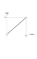
リニア変換部108は、輝度関連値(反射率)と階調値との関係(階調特性)が非線形である入力画像に対して、リニア変換処理を施して、線形の階調特性を有するリニア画像を生成する。図5は、反射率と、入力画像の階調値との関係を示す模式図である。本実施例では、入力画像は、反射率の増加に対して階調値が非線形(対数的)に増加する非線形特性を有するとする。例えば、入力画像の階調特性は、反射率に対して、1/γの累乗であるとする。図6は、反射率と、リニア画像の階調値との関係を示す模式図である。図6に示すように、リニア画像は、反射率の増加に対して階調値が線形に増加する線形の階調特性を有する。リニア変換部108は、入力画像の階調特性を、リニア画像の階調特性に変換する。
The
リニア変換部108は、生成したリニア画像をレンジ変換部109に出力する。なお、リニア変換処理は、その後の処理を簡単化するために行われるものであり、省略されてもよい。
The
レンジ変換部109は、リニア画像にレンジ変換処理を施して、輝度関連値の範囲が表示レンジである出力画像を生成する。なお、レンジ変換部109は、表示部3のガンマ特性を考慮したガンマ変換処理を、レンジ変換処理が施されたリニア画像に施してもよい。例えば、表示部3のガンマ特性がガンマ値=2.2のガンマ特性である場合には、レンジ変換部109は、レンジ変換処理が施されたリニア画像の階調値を1/2.2乗するガンマ変換処理を行う。なお、ガンマ変換処理は省略されてもよい。本実施例では、表示部3のガンマ特性がガンマ値=1のガンマ特性であり、ガンマ変換処理は省略されるとする。
The
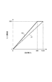
図7を用いて、本実施例に係るレンジ変換処理の一例について具体的に説明する。図7は、リニア画像の階調値(入力階調値)および入力画像の反射率と、出力画像の階調値(出力階調値)および出力画像に基づいて画像を表示した場合の表示輝度と、の対応関係の一例を示す模式図である。図7の横軸は入力階調値を示す。なお、リニア変換処理により、リニア画像の階調値は、入力画像の反射率と線形に対応することから、図7の横軸は、入力画像の反射率を示す。図7の縦軸は出力階調値を示す。第1の実施例において、表示部3の表示特性は、図2に示すように、階調値に対して線形であるとする。したがって、図7の縦軸は、表示部3の表示輝度を示す。
An example of the range conversion process according to the present embodiment will be specifically described with reference to FIG. 7. FIG. 7 shows the gradation value (input gradation value) of the linear image, the reflectance of the input image, the gradation value of the output image (output gradation value), and the display brightness when the image is displayed based on the output image. It is a schematic diagram which shows an example of the correspondence relationship of. The horizontal axis of FIG. 7 indicates the input gradation value. Since the gradation value of the linear image corresponds linearly with the reflectance of the input image by the linear conversion process, the horizontal axis of FIG. 7 indicates the reflectance of the input image. The vertical axis of FIG. 7 shows the output gradation value. In the first embodiment, it is assumed that the display characteristic of the
本実施例では、出力画像の階調値も、入力画像と同様に、10ビットの値(0〜1023)であるものとする。なお、出力画像の階調値の範囲は、上述した範囲より狭くても広くてもよい。出力画像の階調値の範囲は、入力画像の階調値の範囲より狭くても広くてもよい。 In this embodiment, it is assumed that the gradation value of the output image is also a 10-bit value (0 to 1023) like the input image. The range of the gradation value of the output image may be narrower or wider than the above-mentioned range. The range of gradation values of the output image may be narrower or wider than the range of gradation values of the input image.
図7の破線71は、レンジ変換処理を行わない場合の、入力階調値と出力階調値との関係を比較のために示す。レンジ変換処理を行わない場合、出力階調値は、入力階調値と同じ階調値となる。
The
図7の実線72は、本実施例に係るレンジ変換処理を施した場合の入力階調値と出力階調値との関係を示す。本実施例では、以下の式1を用いて、出力階調値Loutが算出される。式1において、D1は入力レンジの最大反射率である。D1は、1000%であるとする。D2は表示レンジの最大反射率である。D2は800%であるとする。Linは入力階調値である。式1において、出力階調値として使用可能な階調値の最大値よりも大きいLoutが算出された場合、Loutは1023が設定される。即ち、1023よりも大きい出力階調値Loutは、1023にクリップ(制限)される。このような変換処理をクリップ処理という。
Lout=(D1÷D2)×Lin ・・・(式1)
The
Lout = (D1 ÷ D2) × Lin ... (Equation 1)
上述のレンジ変換処理により、入力画像の入力レンジのうち表示レンジに含まれる範囲に階調性を有する出力画像が生成される。 By the range conversion process described above, an output image having gradation is generated in the range included in the display range of the input range of the input image.
なお、式1を用いた演算によって、リニア画像の各階調値が変更されてもよいし、そうでなくてもよい。例えば、入力階調値と出力階調値の対応関係を表すLUT(Look Up Table)が、式1に基づいて予め生成されてもよい。そして、LUTを用いて、リニア画像の各階調値が変更されてもよい。具体的には、LUTからリニア画像の階調値(入力階調値)に対応する出力階調値が取得され、リニア画像の各階調値が取得値(取得された出力階調値)に変更されてもよい。 It should be noted that each gradation value of the linear image may or may not be changed by the calculation using the equation 1. For example, a LUT (Look Up Table) representing the correspondence between the input gradation value and the output gradation value may be generated in advance based on the equation 1. Then, each gradation value of the linear image may be changed by using the LUT. Specifically, the output gradation value corresponding to the gradation value (input gradation value) of the linear image is acquired from the LUT, and each gradation value of the linear image is changed to the acquisition value (acquired output gradation value). May be done.
上述のレンジ変換処理を実行することによって、実線72に示すように、出力画像は、入力レンジのうち、表示レンジに対応する輝度関連値(反射率)において、入力画像における輝度関連値と輝度との対応に忠実な輝度で表示される。一方で、破線71で示すように、レンジ変換処理を行わない場合、入力画像の輝度関連値に対応する輝度よりも表示部3に表示される表示輝度が全体的に低下してしまう。これにより、表示部3に表示される画像の視認性が低下する。
By executing the above-mentioned range conversion process, as shown by the
上述のレンジ変換処理により、入力反射率の範囲のうち、表示レンジについて、表示レンジの外側の範囲に比べ、出力画像の階調特性として入力画像の階調特性に近い特性が得られる。それにより、階調特性の変化及び画質の劣化が抑制され、且つ、視認性が高い表示画像を得ることができる。 By the above-mentioned range conversion processing, it is possible to obtain a characteristic of the display range of the input reflectance that is closer to the gradation characteristic of the input image as the gradation characteristic of the output image than the range outside the display range. As a result, it is possible to obtain a display image having high visibility while suppressing changes in gradation characteristics and deterioration of image quality.
なお、出力階調値Loutの算出式は、式1に限らない。レンジ変換処理前の画像の階調特性、レンジ変換処理後の画像の階調特性、入力階調値の範囲、出力階調値の範囲、等に依存して、式1は適宜変更される。 The formula for calculating the output gradation value Lout is not limited to formula 1. Equation 1 is appropriately changed depending on the gradation characteristics of the image before the range conversion processing, the gradation characteristics of the image after the range conversion processing, the range of the input gradation value, the range of the output gradation value, and the like.
本実施例によれば、表示部3の光源や発光素子の経時的な劣化等により、表示部3が表示可能な表示輝度が低下した場合において、入力画像の表示輝度の変化を抑制することが可能となる。表示部3の輝度低下前後における出力画像の表示輝度の変化を用いて、本実施例における画像処理装置1の効果を説明する。例えば、表示部3は、輝度低下前には1000cd/m2まで表示可能であり、輝度低下時には800cd/m2まで表示可能であるとする。また、設定レンジは0〜1000%であるとする。
According to this embodiment, when the display brightness that can be displayed by the
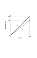
図8は、入力画像の反射率に対する出力画像の階調値を示す模式図である。図8の横軸は、入力画像の反射率を示す。図8の縦軸は、出力画像の階調値を示す。図8の破線81は、表示レンジが0〜1000%である場合の、入力画像の反射率に対する出力画像Aの階調値を示す。破線81は、輝度低下前の表示部3に対してキャリブレーション処理を実行して得られた表示最大輝度(1000cd/m2)に基づいて決定された参照レンジと設定レンジとを用いて、レンジ変換処理を施して生成された出力画像の階調値を示すといえる。また、破線81は、設定レンジのみに基づいて、レンジ変換処理を施して生成された出力画像の階調値を示すともいえる。
FIG. 8 is a schematic diagram showing the gradation value of the output image with respect to the reflectance of the input image. The horizontal axis of FIG. 8 indicates the reflectance of the input image. The vertical axis of FIG. 8 shows the gradation value of the output image. The
一方、図8の直線82は、表示レンジが0〜800%である場合の、入力画像の反射率に対する出力画像Bの階調値を示す。すなわち、直線82は、輝度低下時の表示部3に対してキャリブレーション処理を実行して得られた表示最大輝度(800cd/m2)に基づいて決定された参照レンジと設定レンジとを用いて、レンジ変換処理を施して生成された出力画像の階調値を示す。
On the other hand, the
つまり、第1の実施例に記載の処理を実行することにより、表示部3の輝度低下の前後で、生成される出力画像は、出力画像Aから出力画像Bに変化する。一方で、表示最大輝度を用いて表示レンジを変更しない場合、表示部3の輝度低下によらず、出力画像Aが出力される。
That is, by executing the process described in the first embodiment, the output image generated changes from the output image A to the output image B before and after the decrease in the brightness of the
図9は、出力画像Aおよび出力画像Bに基づいて表示部3に画像を表示した場合の、入力画像の輝度関連値(反射率)と表示輝度との関係を示す模式図である。図9の横軸は、入力画像の輝度関連値(反射率)を示す。図9の縦軸は、出力画像の表示輝度を示す。
FIG. 9 is a schematic diagram showing the relationship between the brightness-related value (reflectance) of the input image and the display brightness when the image is displayed on the
図9の破線91は、輝度低下前の表示部3が出力画像Aに基づいて画像を表示した場合の、表示輝度を示す。出力画像Aは、入力画像の輝度関連値の最大値(1000%)に出力画像の階調値の最大値(1023)が対応する線形の階調特性を有する画像である。表示部3は、階調値に対して表示輝度が線形の表示特性であることから、出力画像Aの階調値の最大値は、表示部3が表示可能な最大の表示輝度(1000cd/m2)に対応し、階調値は表示輝度と線形に対応する。したがって、入力画像の輝度関連値と輝度との関係に忠実な輝度で、表示部3で表示される。
The
図9の一点破線92は、輝度低下時の表示部3が出力画像Aに基づいて画像を表示した場合の、表示輝度を示す。表示輝度が低下した場合、出力画像Aの階調値は、表示部3が表示可能な最大の表示輝度(800cd/m2)までの範囲に線形に対応する。つまり、出力画像は、入力画像の輝度関連値に対応する輝度よりも全体的に低い輝度で表示部3に表示される。
The alternate long and short dash line 92 in FIG. 9 indicates the display brightness when the
図9の実線93は、輝度低下時の表示部3が出力画像Bに基づいて画像を表示した場合の、表示輝度を示す。出力画像Bは、輝度低下時の表示部3が表示可能な最大の表示輝度(800cd/m2)に基づく、表示レンジ(0〜800%)に対応するようにレンジ変換処理を施された画像である。出力画像Bの階調値の最大値は、表示レンジの最大値(800%)に対応し、階調値は表示輝度と線形に対応する。したがって、入力レンジのうち、表示レンジに含まれる入力画像の輝度関連値において、入力画像の輝度関連値と輝度との関係に忠実な輝度で、表示部3で表示される。
The
本実施例に記載の画像処理装置によれば、上述の処理を実行することにより、キャリブレーションにより測定装置2が測定した表示部3の表示輝度の最大値(表示最大輝度)に基づいて決定された表示レンジに対応する出力画像を生成することが可能となる。したがって、表示部3が表示可能な輝度が、経時的な劣化や、光源の劣化等により低下した場合においても、表示可能な輝度の範囲の階調特性を忠実に表現することが可能となる。したがって、表示部3が表示可能な最大の表示輝度が変化する場合に、入力画像のうち、ユーザが指定した表示レンジに対応する領域の表示輝度が変化することを抑制することが可能となる。
According to the image processing apparatus described in this embodiment, by executing the above-mentioned processing, it is determined based on the maximum value (display maximum luminance) of the display luminance of the
また、画像処理部101は、表示レンジ決定部105が決定した表示レンジを示すグラフィック画像を、On Screen Display(OSD)として生成し、出力画像に合成して表示部3に出力してもよい。
Further, the
図10は、画像処理部101が生成する表示レンジを示すOSD画像を示す模式図である。例えば、OSD画像は、ユーザが指定した設定レンジと、出力画像の表示レンジとを合わせて表示するためのグラフィック画像であるとする。これにより、ユーザは、設定したダイナミックレンジ(設定)のうち、実際に入力画像の階調特性に忠実に表示されるダイナミックレンジ(表示レンジ)を認識することが容易となる。図10において、輝度レンジ設定は、設定レンジと表示レンジとを表示する画面を示している。表示部3が輝度低下前(初期)である場合には、表示レンジ(1000%)は、設定レンジ(1000%)と同等である。表示部3が輝度低下時(劣化時)である場合には、表示レンジ(800%)は、設定レンジ(1000%)よりも低下し、OSD画像に表示レンジが低下したことが示される。
FIG. 10 is a schematic view showing an OSD image showing a display range generated by the
なお、画像処理装置1は、キャリブレーションを任意のタイミングで実行し、取得した表示最大輝度に基づいて、時々刻々と動的に表示レンジを決定することも可能である。これにより、表示部3の温度や、使用環境による表示輝度の変動による画像への影響を抑制することが可能となる。例えば、測定装置2は、表示部3に組み込まれていてもよい。表示部3の画面の端部等、ユーザが画像を視認する際に妨げにならない位置に、測定装置2を配置することにより、任意のタイミングでキャリブレーションを実行し、表示最大輝度を取得することが可能となる。
It is also possible for the image processing apparatus 1 to execute calibration at an arbitrary timing and dynamically determine the display range from moment to moment based on the acquired maximum display brightness. This makes it possible to suppress the influence on the image due to the temperature of the
(第2の実施例)
本発明の第2の実施例における画像処理装置1は、入力画像の反射率が特定の範囲に含まれる場合、反射率に対して表示輝度が線形の関係となるように表示し、それ以外の範囲は、所定の指数関数に基づいて圧縮して表示するように、出力画像を生成する。画像処理装置1は、ユーザが設定した設定レンジを、特定の範囲とする。
(Second Example)
When the reflectance of the input image is included in a specific range, the image processing device 1 in the second embodiment of the present invention displays so that the display brightness has a linear relationship with the reflectance, and other than that. The range produces an output image to be compressed and displayed based on a given exponential function. The image processing device 1 sets a set range set by the user as a specific range.
第2の実施例における画像処理装置1の装置構成図、および機能ブロック図は、第1の実施例と同様である。第2の実施例における画像処理装置1のうち、表示レンジ決定部105、およびレンジ変換部109以外の機能ブロックは、第1の実施例と同様であることから説明を省略する。
The device configuration diagram and the functional block diagram of the image processing apparatus 1 in the second embodiment are the same as those in the first embodiment. Of the image processing devices 1 in the second embodiment, the functional blocks other than the display
表示レンジ決定部105は、設定レンジ取得部103から、入力画像の反射率に対して表示輝度が線形となる設定レンジを示す情報を取得する。さらに、表示レンジ決定部105は、測定輝度取得部104から、キャリブレーションによって得られた表示部3の表示可能な最大の表示輝度である表示最大輝度を取得する。例えば、設定レンジは、0〜500%であるとする。
The display
レンジ変換部109は、設定レンジに含まれる反射率に対して表示輝度が線形になるように、リニア画像から出力画像を生成する。さらに、レンジ変換部109は、設定レンジに含まれない反射率が設定レンジの上限値に対応する表示輝度から表示最大輝度までの表示輝度の範囲で表示されるように、リニア画像から出力画像を生成する。言い換えると、レンジ変換部109は、設定レンジに含まれる輝度関連値に対応する領域が、それ以外の領域よりも、出力画像において、入力画像の階調特性に近くなるように出力画像を生成する。例えば、入力画像のダイナミックレンジ(入力レンジ)が0〜1000%、表示部3の表示可能な輝度の最大値(表示最大輝度)は800cd/m2であるとする。
The
図11は、入力画像の反射率に対して、第2の実施例の画像処理装置1が生成した出力画像に基づいて表示部3が画像を表示した場合の輝度を示す模式図である。図11に示すように、入力画像の反射率が設定レンジ(0〜500%)に含まれる場合、反射率に対して、輝度が線形の関係になるように出力画像を生成される。さらに、設定レンジを超える(>500%)反射率は、設定レンジの上限値(500%)に対応する表示輝度500cd/m2から、表示最大輝度(800cd/m2)までの範囲で表示されるように階調が圧縮される。
FIG. 11 is a schematic diagram showing the brightness when the
第2の実施例によれば、表示部3の表示可能な輝度の最大値が光源の経時的な劣化等により低下した場合に、少なくとも設定レンジに含まれる反射率に対応する入力画像の表示特性の変化を抑制することが可能となる。また、第1の実施例に記載したように、例えば、表示部3の表示輝度の最大値が低下した場合に、少なくとも設定レンジに含まれる反射率に対応する入力画像の表示特性の変化を抑制することが可能となる。したがって、表示部3が表示可能な最大の表示輝度が変化する場合に、入力画像のうち、ユーザが指定した設定レンジに対応する領域の表示輝度が変化することを抑制することが可能となる。
According to the second embodiment, when the maximum value of the displayable brightness of the
図12は、輝度低下前後における入力画像の輝度関連値に対する表示輝度の変化を示す模式図である。図12の横軸は、入力画像の輝度関連値(反射率)を示す。図12の縦軸は、表示輝度を示す。 FIG. 12 is a schematic diagram showing a change in display brightness with respect to a brightness-related value of an input image before and after the decrease in brightness. The horizontal axis of FIG. 12 indicates the brightness-related value (reflectance) of the input image. The vertical axis of FIG. 12 indicates the display brightness.
図12の破線121は、輝度低下前の表示部3に対してキャリブレーションを実行して得られた表示最大輝度に基づいて、生成された出力画像Cの表示輝度を示す。また、図12の実線122は、輝度低下時の表示部3に対してキャリブレーションを実行して得られた表示最大輝度に基づいて、生成された出力画像Cの表示輝度を示す。表示部3の表示輝度は、輝度低下前は800cd/m2まで表示可能であり、輝度低下時は600cd/m2まで表示可能であるとする。設定レンジは、0〜500%であるとする。
The
表示部3の表示輝度の最大値が、800cd/m2から600cd/m2に低下した場合に、入力画像の反射率と画像処理装置1が出力する出力画像に基づいて表示される画像の輝度との関係は、破線121から実線122に変化する。したがって、表示部3が表示可能な表示輝度が低下した場合においても、設定レンジ(0〜500%)において、入力画像の輝度関連値と輝度との関係に忠実に輝度が輝度関連値に対して線形の特性で表示される。
When the maximum value of the display luminance of the
これにより、表示部3の表示可能な輝度が低下しても、ユーザが入力画像に関連付けられた輝度関連値に対して忠実に輝度を表示したい設定レンジの表示輝度が低下することを抑制することが可能となる。
As a result, even if the displayable brightness of the
<その他の実施例>
本発明は、上述の実施例の1以上の機能を実現するプログラムを、ネットワーク又は記憶媒体を介してシステム又は装置に供給し、そのシステム又は装置のコンピュータにおける1つ以上のプロセッサーがプログラムを読出し実行する処理でも実現可能である。また、1以上の機能を実現する回路(例えば、ASIC)によっても実現可能である。
<Other Examples>
The present invention supplies a program that realizes one or more functions of the above-described embodiment to a system or device via a network or storage medium, and one or more processors in the computer of the system or device reads and executes the program. It can also be realized by the processing to be performed. It can also be realized by a circuit (for example, ASIC) that realizes one or more functions.
1 画像処理装置
2 測定装置
3 表示部
100 制御部
101 画像処理部
102 入力レンジ取得部
103 設定レンジ取得部
104 測定輝度取得部
105 表示レンジ決定部
106 出力部
107 校正制御部
108 リニア変換部
109 レンジ変換部
200 記憶部
300 操作部
1
Claims (15)
前記測定値に基づいて出力ダイナミックレンジを設定する設定手段と、
前記出力ダイナミックレンジに基づいて入力画像の階調値を変換して、出力画像を生成する画像処理手段と、
前記出力画像を前記表示手段に出力する出力手段と、
を備え、
前記画像処理手段は、前記出力ダイナミックレンジの取り得る最大の輝度関連値および前記測定値のうち少なくとも一方を示すグラフィック画像を前記出力画像に合成することを特徴とする画像処理装置。 A first acquisition means for acquiring a measured value from a measuring means for measuring the brightness of an image displayed on the display means, and
A setting means for setting the output dynamic range based on the measured value, and
An image processing means that converts the gradation value of the input image based on the output dynamic range to generate an output image, and
An output means that outputs the output image to the display means, and
With
The image processing means is an image processing apparatus characterized in that a graphic image showing at least one of the maximum possible brightness-related value and the measured value of the output dynamic range is combined with the output image.
ことを特徴とする請求項5乃至請求項8のいずれか1項に記載の画像処理装置。 The image processing apparatus according to any one of claims 5 to 8, wherein the brightness-related value is a reflectance when light is reflected by an object.
ことを特徴とする請求項5乃至請求項8のいずれか1項に記載の画像処理装置。 The image processing apparatus according to any one of claims 5 to 8, wherein the brightness-related value is a value indicating brightness.
前記表示手段と、
を備える表示装置。 The image processing apparatus according to any one of claims 1 to 10.
With the display means
A display device comprising.
前記測定値に基づいて出力ダイナミックレンジを設定する設定工程と、
前記出力ダイナミックレンジに基づいて入力画像の階調値を変換して出力画像を生成する画像処理工程と、
前記出力画像を前記表示手段に出力する出力工程と、
を備え、
前記画像処理工程は、前記出力ダイナミックレンジの取り得る最大の輝度関連値および前記測定値のうち少なくとも一方を示すグラフィック画像を前記出力画像に合成することを特徴とする画像処理装置の制御方法。 The acquisition process of acquiring the measured value from the measuring means for measuring the brightness of the image displayed on the display means, and
A setting process for setting the output dynamic range based on the measured values, and
An image processing step of converting the gradation value of an input image based on the output dynamic range to generate an output image, and
An output process for outputting the output image to the display means, and
With
The image processing step is a control method of an image processing apparatus, characterized in that a graphic image showing at least one of the maximum possible brightness-related value and the measured value of the output dynamic range is combined with the output image.
Priority Applications (3)
| Application Number | Priority Date | Filing Date | Title |
|---|---|---|---|
| JP2016148940A JP6779695B2 (en) | 2016-07-28 | 2016-07-28 | Image processing device and its control method, display device |
| CN201710613039.4A CN107665480B (en) | 2016-07-28 | 2017-07-25 | Image processing apparatus, control method thereof, display apparatus, and storage medium |
| US15/658,917 US10255883B2 (en) | 2016-07-28 | 2017-07-25 | Image processing apparatus, method for controlling the same, display apparatus, and storage medium |
Applications Claiming Priority (1)
| Application Number | Priority Date | Filing Date | Title |
|---|---|---|---|
| JP2016148940A JP6779695B2 (en) | 2016-07-28 | 2016-07-28 | Image processing device and its control method, display device |
Publications (3)
| Publication Number | Publication Date |
|---|---|
| JP2018017931A JP2018017931A (en) | 2018-02-01 |
| JP2018017931A5 JP2018017931A5 (en) | 2019-08-08 |
| JP6779695B2 true JP6779695B2 (en) | 2020-11-04 |
Family
ID=61012187
Family Applications (1)
| Application Number | Title | Priority Date | Filing Date |
|---|---|---|---|
| JP2016148940A Active JP6779695B2 (en) | 2016-07-28 | 2016-07-28 | Image processing device and its control method, display device |
Country Status (3)
| Country | Link |
|---|---|
| US (1) | US10255883B2 (en) |
| JP (1) | JP6779695B2 (en) |
| CN (1) | CN107665480B (en) |
Families Citing this family (5)
| Publication number | Priority date | Publication date | Assignee | Title |
|---|---|---|---|---|
| US10403233B2 (en) * | 2017-01-17 | 2019-09-03 | Canon Kabushiki Kaisha | Image processing apparatus and image processing method |
| JP6650915B2 (en) * | 2017-08-22 | 2020-02-19 | キヤノン株式会社 | Display device and display control method |
| JP2019159252A (en) * | 2018-03-16 | 2019-09-19 | キヤノン株式会社 | Control device, display device, control method, and program |
| JP7418690B2 (en) * | 2019-10-25 | 2024-01-22 | 株式会社Jvcケンウッド | Display control device, display system, display control method and program |
| JP7361958B2 (en) * | 2021-02-02 | 2023-10-16 | Eizo株式会社 | Image display system, image display device, image display method and computer program |
Family Cites Families (27)
| Publication number | Priority date | Publication date | Assignee | Title |
|---|---|---|---|---|
| WO2002100093A1 (en) * | 2001-05-31 | 2002-12-12 | Matsushita Electric Industrial Co., Ltd. | Image processing apparatus and image processing method |
| JP4143425B2 (en) | 2003-01-16 | 2008-09-03 | 富士フイルム株式会社 | Image processing method and apparatus, and image processing program |
| JP2006251516A (en) * | 2005-03-11 | 2006-09-21 | Pioneer Electronic Corp | Display device and multi-display system |
| JP5127321B2 (en) * | 2007-06-28 | 2013-01-23 | 株式会社東芝 | Image display device, image display method, and image display program |
| CN101588436B (en) * | 2008-05-20 | 2013-03-27 | 株式会社理光 | Method, device and digital camera for compressing dynamic range of original image |
| JP5355190B2 (en) * | 2009-04-08 | 2013-11-27 | キヤノン株式会社 | Image display apparatus and method, and program |
| CN102483905A (en) * | 2009-09-29 | 2012-05-30 | 松下电器产业株式会社 | Display device and display method |
| EP2504829A4 (en) * | 2009-11-27 | 2012-10-31 | Canon Kk | Image display apparatus |
| JP5672796B2 (en) * | 2010-01-13 | 2015-02-18 | 株式会社ニコン | Image processing apparatus and image processing method |
| KR20110137634A (en) * | 2010-06-17 | 2011-12-23 | 삼성전자주식회사 | Method for generating sketch image and display apparaus applying the same |
| JP5972013B2 (en) * | 2011-06-30 | 2016-08-17 | キヤノン株式会社 | Display device and control method thereof |
| JP5939765B2 (en) * | 2011-11-02 | 2016-06-22 | キヤノン株式会社 | CALIBRATION DEVICE, ITS CONTROL METHOD, IMAGE DISPLAY DEVICE, AND IMAGE DISPLAY SYSTEM |
| US20130169663A1 (en) * | 2011-12-30 | 2013-07-04 | Samsung Electronics Co., Ltd. | Apparatus and method for displaying images and apparatus and method for processing images |
| JP5994276B2 (en) * | 2012-02-16 | 2016-09-21 | セイコーエプソン株式会社 | Image processing apparatus, display apparatus, and image processing method |
| JP5919988B2 (en) * | 2012-04-13 | 2016-05-18 | 株式会社デンソー | Image processing device |
| EP2899688A4 (en) * | 2012-09-20 | 2016-04-27 | Sharp Kk | Image processing device, image display device, image capture device, image printing device, gradation conversion method, and program |
| CN103024300B (en) * | 2012-12-25 | 2015-11-25 | 华为技术有限公司 | A kind of method for high dynamic range image display and device |
| JP6105925B2 (en) * | 2012-12-27 | 2017-03-29 | 株式会社東芝 | Image processing apparatus and image display apparatus |
| KR102053618B1 (en) * | 2013-04-11 | 2019-12-09 | 엘지디스플레이 주식회사 | Electronic device, display controlling apparatus and method there of |
| JP6439418B2 (en) * | 2014-03-05 | 2018-12-19 | ソニー株式会社 | Image processing apparatus, image processing method, and image display apparatus |
| JP6443857B2 (en) * | 2014-06-05 | 2018-12-26 | キヤノン株式会社 | Image processing apparatus, image processing method, and program |
| MX357793B (en) * | 2014-06-23 | 2018-07-25 | Panasonic Ip Man Co Ltd | Conversion method and conversion apparatus. |
| JP6478499B2 (en) * | 2014-07-07 | 2019-03-06 | キヤノン株式会社 | Image processing apparatus, image processing method, and program |
| JP6421504B2 (en) * | 2014-07-28 | 2018-11-14 | ソニー株式会社 | Image processing apparatus and image processing method |
| JP2016058848A (en) * | 2014-09-08 | 2016-04-21 | ソニー株式会社 | Image processing system and image processing method |
| US20170330504A1 (en) * | 2014-11-28 | 2017-11-16 | Linkpro Co., Ltd. | Image processing apparatus and image processing method |
| JP2016111389A (en) * | 2014-12-02 | 2016-06-20 | Necディスプレイソリューションズ株式会社 | Display device, display system, display method, and computer program |
-
2016
- 2016-07-28 JP JP2016148940A patent/JP6779695B2/en active Active
-
2017
- 2017-07-25 CN CN201710613039.4A patent/CN107665480B/en active Active
- 2017-07-25 US US15/658,917 patent/US10255883B2/en active Active
Also Published As
| Publication number | Publication date |
|---|---|
| CN107665480A (en) | 2018-02-06 |
| CN107665480B (en) | 2021-05-18 |
| US20180033400A1 (en) | 2018-02-01 |
| US10255883B2 (en) | 2019-04-09 |
| JP2018017931A (en) | 2018-02-01 |
Similar Documents
| Publication | Publication Date | Title |
|---|---|---|
| JP6779695B2 (en) | Image processing device and its control method, display device | |
| US9972078B2 (en) | Image processing apparatus | |
| JP6700908B2 (en) | Display device and display method | |
| JP6700880B2 (en) | Information processing apparatus and information processing method | |
| JP5897159B2 (en) | Display device and control method thereof | |
| JP2015142276A (en) | Display device, display device control method, and program | |
| US10565913B2 (en) | Image display apparatus and control method thereof | |
| JP2014139647A (en) | Display device, driving method of display device, and electronic apparatus | |
| JP6771947B2 (en) | Display device and its control method | |
| WO2017037997A1 (en) | Display apparatus, method for controlling the same, program, and storage medium | |
| JP6617432B2 (en) | Image processing apparatus and program | |
| JP2008292680A (en) | Output value setting method, output value setting device and display device | |
| US11763777B2 (en) | Image display device, image display system, image display method, and computer program for providing a low-luminance grayscale standard display function (GSDF) display | |
| US10282828B2 (en) | Image processing apparatus to convert gradation values of an input image, control method thereof, and program | |
| JP2012151598A (en) | Image processing device and image processing program | |
| JP2019080156A (en) | Image processing method and image processing apparatus | |
| JP5655335B2 (en) | Image processing apparatus, image display apparatus, and program | |
| JP2015139131A (en) | Image processing device, image processing method and program | |
| US20140327695A1 (en) | Image processing apparatus and control method therefor | |
| JP6628925B2 (en) | Image display device and control method thereof | |
| JP2015171039A (en) | Color processing apparatus and color processing method | |
| US20210217385A1 (en) | Information-processing apparatus, display device, and information-processing method | |
| US11341622B2 (en) | Image processing apparatus, image capturing apparatus, image processing method, and storage medium | |
| US20190114994A1 (en) | Image processing apparatus, image processing method, and non-transitory computer readable medium | |
| JP2020190711A (en) | Image processing device and image processing method |
Legal Events
| Date | Code | Title | Description |
|---|---|---|---|
| A521 | Request for written amendment filed |
Free format text: JAPANESE INTERMEDIATE CODE: A523 Effective date: 20190626 |
|
| A621 | Written request for application examination |
Free format text: JAPANESE INTERMEDIATE CODE: A621 Effective date: 20190626 |
|
| A977 | Report on retrieval |
Free format text: JAPANESE INTERMEDIATE CODE: A971007 Effective date: 20200527 |
|
| A131 | Notification of reasons for refusal |
Free format text: JAPANESE INTERMEDIATE CODE: A131 Effective date: 20200630 |
|
| A521 | Request for written amendment filed |
Free format text: JAPANESE INTERMEDIATE CODE: A523 Effective date: 20200709 |
|
| A131 | Notification of reasons for refusal |
Free format text: JAPANESE INTERMEDIATE CODE: A131 Effective date: 20200804 |
|
| A521 | Request for written amendment filed |
Free format text: JAPANESE INTERMEDIATE CODE: A523 Effective date: 20200828 |
|
| TRDD | Decision of grant or rejection written | ||
| A01 | Written decision to grant a patent or to grant a registration (utility model) |
Free format text: JAPANESE INTERMEDIATE CODE: A01 Effective date: 20200915 |
|
| A61 | First payment of annual fees (during grant procedure) |
Free format text: JAPANESE INTERMEDIATE CODE: A61 Effective date: 20201014 |
|
| R151 | Written notification of patent or utility model registration |
Ref document number: 6779695 Country of ref document: JP Free format text: JAPANESE INTERMEDIATE CODE: R151 |