CN105943145B - Device and method for bone adjustment using wireless energy transmission - Google Patents
Device and method for bone adjustment using wireless energy transmission Download PDFInfo
- Publication number
- CN105943145B CN105943145B CN201610320491.7A CN201610320491A CN105943145B CN 105943145 B CN105943145 B CN 105943145B CN 201610320491 A CN201610320491 A CN 201610320491A CN 105943145 B CN105943145 B CN 105943145B
- Authority
- CN
- China
- Prior art keywords
- energy
- implantable
- bone
- implantable device
- adjustment
- Prior art date
- Legal status (The legal status is an assumption and is not a legal conclusion. Google has not performed a legal analysis and makes no representation as to the accuracy of the status listed.)
- Active
Links
Images


Classifications
-
- A—HUMAN NECESSITIES
- A61—MEDICAL OR VETERINARY SCIENCE; HYGIENE
- A61B—DIAGNOSIS; SURGERY; IDENTIFICATION
- A61B17/00—Surgical instruments, devices or methods, e.g. tourniquets
- A61B17/56—Surgical instruments or methods for treatment of bones or joints; Devices specially adapted therefor
- A61B17/58—Surgical instruments or methods for treatment of bones or joints; Devices specially adapted therefor for osteosynthesis, e.g. bone plates, screws, setting implements or the like
- A61B17/68—Internal fixation devices, including fasteners and spinal fixators, even if a part thereof projects from the skin
- A61B17/72—Intramedullary pins, nails or other devices
- A61B17/7216—Intramedullary pins, nails or other devices for bone lengthening or compression
-
- A—HUMAN NECESSITIES
- A61—MEDICAL OR VETERINARY SCIENCE; HYGIENE
- A61B—DIAGNOSIS; SURGERY; IDENTIFICATION
- A61B17/00—Surgical instruments, devices or methods, e.g. tourniquets
- A61B17/56—Surgical instruments or methods for treatment of bones or joints; Devices specially adapted therefor
- A61B17/58—Surgical instruments or methods for treatment of bones or joints; Devices specially adapted therefor for osteosynthesis, e.g. bone plates, screws, setting implements or the like
- A61B17/68—Internal fixation devices, including fasteners and spinal fixators, even if a part thereof projects from the skin
- A61B17/70—Spinal positioners or stabilisers ; Bone stabilisers comprising fluid filler in an implant
- A61B17/7001—Screws or hooks combined with longitudinal elements which do not contact vertebrae
- A61B17/7002—Longitudinal elements, e.g. rods
- A61B17/7014—Longitudinal elements, e.g. rods with means for adjusting the distance between two screws or hooks
- A61B17/7016—Longitudinal elements, e.g. rods with means for adjusting the distance between two screws or hooks electric or electromagnetic means
-
- A—HUMAN NECESSITIES
- A61—MEDICAL OR VETERINARY SCIENCE; HYGIENE
- A61B—DIAGNOSIS; SURGERY; IDENTIFICATION
- A61B17/00—Surgical instruments, devices or methods, e.g. tourniquets
- A61B17/56—Surgical instruments or methods for treatment of bones or joints; Devices specially adapted therefor
- A61B17/58—Surgical instruments or methods for treatment of bones or joints; Devices specially adapted therefor for osteosynthesis, e.g. bone plates, screws, setting implements or the like
- A61B17/68—Internal fixation devices, including fasteners and spinal fixators, even if a part thereof projects from the skin
- A61B17/70—Spinal positioners or stabilisers ; Bone stabilisers comprising fluid filler in an implant
- A61B17/7001—Screws or hooks combined with longitudinal elements which do not contact vertebrae
- A61B17/7002—Longitudinal elements, e.g. rods
- A61B17/7014—Longitudinal elements, e.g. rods with means for adjusting the distance between two screws or hooks
- A61B17/7017—Longitudinal elements, e.g. rods with means for adjusting the distance between two screws or hooks pneumatic or hydraulic means
-
- A—HUMAN NECESSITIES
- A61—MEDICAL OR VETERINARY SCIENCE; HYGIENE
- A61B—DIAGNOSIS; SURGERY; IDENTIFICATION
- A61B17/00—Surgical instruments, devices or methods, e.g. tourniquets
- A61B17/56—Surgical instruments or methods for treatment of bones or joints; Devices specially adapted therefor
- A61B17/58—Surgical instruments or methods for treatment of bones or joints; Devices specially adapted therefor for osteosynthesis, e.g. bone plates, screws, setting implements or the like
- A61B17/68—Internal fixation devices, including fasteners and spinal fixators, even if a part thereof projects from the skin
- A61B17/70—Spinal positioners or stabilisers ; Bone stabilisers comprising fluid filler in an implant
- A61B17/7062—Devices acting on, attached to, or simulating the effect of, vertebral processes, vertebral facets or ribs ; Tools for such devices
-
- A—HUMAN NECESSITIES
- A61—MEDICAL OR VETERINARY SCIENCE; HYGIENE
- A61B—DIAGNOSIS; SURGERY; IDENTIFICATION
- A61B17/00—Surgical instruments, devices or methods, e.g. tourniquets
- A61B17/56—Surgical instruments or methods for treatment of bones or joints; Devices specially adapted therefor
- A61B17/58—Surgical instruments or methods for treatment of bones or joints; Devices specially adapted therefor for osteosynthesis, e.g. bone plates, screws, setting implements or the like
- A61B17/68—Internal fixation devices, including fasteners and spinal fixators, even if a part thereof projects from the skin
- A61B17/72—Intramedullary pins, nails or other devices
- A61B17/7233—Intramedullary pins, nails or other devices with special means of locking the nail to the bone
- A61B17/7258—Intramedullary pins, nails or other devices with special means of locking the nail to the bone with laterally expanding parts, e.g. for gripping the bone
-
- A—HUMAN NECESSITIES
- A61—MEDICAL OR VETERINARY SCIENCE; HYGIENE
- A61B—DIAGNOSIS; SURGERY; IDENTIFICATION
- A61B17/00—Surgical instruments, devices or methods, e.g. tourniquets
- A61B17/56—Surgical instruments or methods for treatment of bones or joints; Devices specially adapted therefor
- A61B17/58—Surgical instruments or methods for treatment of bones or joints; Devices specially adapted therefor for osteosynthesis, e.g. bone plates, screws, setting implements or the like
- A61B17/60—Surgical instruments or methods for treatment of bones or joints; Devices specially adapted therefor for osteosynthesis, e.g. bone plates, screws, setting implements or the like for external osteosynthesis, e.g. distractors, contractors
- A61B17/66—Alignment, compression or distraction mechanisms
-
- A—HUMAN NECESSITIES
- A61—MEDICAL OR VETERINARY SCIENCE; HYGIENE
- A61B—DIAGNOSIS; SURGERY; IDENTIFICATION
- A61B17/00—Surgical instruments, devices or methods, e.g. tourniquets
- A61B17/56—Surgical instruments or methods for treatment of bones or joints; Devices specially adapted therefor
- A61B17/58—Surgical instruments or methods for treatment of bones or joints; Devices specially adapted therefor for osteosynthesis, e.g. bone plates, screws, setting implements or the like
- A61B17/68—Internal fixation devices, including fasteners and spinal fixators, even if a part thereof projects from the skin
- A61B17/72—Intramedullary pins, nails or other devices
- A61B17/7233—Intramedullary pins, nails or other devices with special means of locking the nail to the bone
-
- A—HUMAN NECESSITIES
- A61—MEDICAL OR VETERINARY SCIENCE; HYGIENE
- A61B—DIAGNOSIS; SURGERY; IDENTIFICATION
- A61B17/00—Surgical instruments, devices or methods, e.g. tourniquets
- A61B17/56—Surgical instruments or methods for treatment of bones or joints; Devices specially adapted therefor
- A61B17/58—Surgical instruments or methods for treatment of bones or joints; Devices specially adapted therefor for osteosynthesis, e.g. bone plates, screws, setting implements or the like
- A61B17/68—Internal fixation devices, including fasteners and spinal fixators, even if a part thereof projects from the skin
- A61B17/72—Intramedullary pins, nails or other devices
- A61B17/7291—Intramedullary pins, nails or other devices for small bones, e.g. in the foot, ankle, hand or wrist
-
- A—HUMAN NECESSITIES
- A61—MEDICAL OR VETERINARY SCIENCE; HYGIENE
- A61B—DIAGNOSIS; SURGERY; IDENTIFICATION
- A61B17/00—Surgical instruments, devices or methods, e.g. tourniquets
- A61B2017/00017—Electrical control of surgical instruments
- A61B2017/00212—Electrical control of surgical instruments using remote controls
-
- A—HUMAN NECESSITIES
- A61—MEDICAL OR VETERINARY SCIENCE; HYGIENE
- A61B—DIAGNOSIS; SURGERY; IDENTIFICATION
- A61B17/00—Surgical instruments, devices or methods, e.g. tourniquets
- A61B2017/00367—Details of actuation of instruments, e.g. relations between pushing buttons, or the like, and activation of the tool, working tip, or the like
- A61B2017/00398—Details of actuation of instruments, e.g. relations between pushing buttons, or the like, and activation of the tool, working tip, or the like using powered actuators, e.g. stepper motors, solenoids
-
- A—HUMAN NECESSITIES
- A61—MEDICAL OR VETERINARY SCIENCE; HYGIENE
- A61B—DIAGNOSIS; SURGERY; IDENTIFICATION
- A61B17/00—Surgical instruments, devices or methods, e.g. tourniquets
- A61B2017/00367—Details of actuation of instruments, e.g. relations between pushing buttons, or the like, and activation of the tool, working tip, or the like
- A61B2017/00411—Details of actuation of instruments, e.g. relations between pushing buttons, or the like, and activation of the tool, working tip, or the like actuated by application of energy from an energy source outside the body
-
- A—HUMAN NECESSITIES
- A61—MEDICAL OR VETERINARY SCIENCE; HYGIENE
- A61B—DIAGNOSIS; SURGERY; IDENTIFICATION
- A61B17/00—Surgical instruments, devices or methods, e.g. tourniquets
- A61B2017/00535—Surgical instruments, devices or methods, e.g. tourniquets pneumatically or hydraulically operated
- A61B2017/00539—Surgical instruments, devices or methods, e.g. tourniquets pneumatically or hydraulically operated hydraulically
-
- A—HUMAN NECESSITIES
- A61—MEDICAL OR VETERINARY SCIENCE; HYGIENE
- A61B—DIAGNOSIS; SURGERY; IDENTIFICATION
- A61B90/00—Instruments, implements or accessories specially adapted for surgery or diagnosis and not covered by any of the groups A61B1/00 - A61B50/00, e.g. for luxation treatment or for protecting wound edges
- A61B90/06—Measuring instruments not otherwise provided for
- A61B2090/061—Measuring instruments not otherwise provided for for measuring dimensions, e.g. length
Landscapes
- Health & Medical Sciences (AREA)
- Orthopedic Medicine & Surgery (AREA)
- Life Sciences & Earth Sciences (AREA)
- Surgery (AREA)
- Neurology (AREA)
- Molecular Biology (AREA)
- General Health & Medical Sciences (AREA)
- Biomedical Technology (AREA)
- Heart & Thoracic Surgery (AREA)
- Medical Informatics (AREA)
- Nuclear Medicine, Radiotherapy & Molecular Imaging (AREA)
- Animal Behavior & Ethology (AREA)
- Engineering & Computer Science (AREA)
- Public Health (AREA)
- Veterinary Medicine (AREA)
- Physics & Mathematics (AREA)
- Electromagnetism (AREA)
- Prostheses (AREA)
- Surgical Instruments (AREA)
- Apparatus For Radiation Diagnosis (AREA)
- Electrotherapy Devices (AREA)
Abstract
A method and apparatus for bone adjustment in a mammal is provided, wherein a set of means for applying a force to an anchoring device anchored in the bone is implanted in the mammal. The method and device have utility in medical and cosmetic bone adjustments including, for example, lengthening, remodeling and remodeling of bones, joints or vertebrae in congenital deformity correction, prosthetic orthopedic surgery, and the like.
Description
The present application is a divisional application of an application entitled "apparatus and method for bone adjustment using wireless energy transmission" (apparatus for bone adjustment using wireless energy transmission modified by examiner according to the authority when authorized) on the date of application of 29/10/2009 under the name of application No. 200980153587.7.
Technical Field
The present invention relates to methods and devices for bone adjustment of medical and cosmetic nature, and more particularly to implantable devices, such as but not limited to implantable hydraulic devices, for adjusting the position, length, strength or function of bone in the human or animal body.
Background
The practice of fixing fractured bones to promote healing has been practiced for hundreds of years. Starting from simple splints and sometimes rather unsanitary bandages, the invention of plaster casts opens a new era of orthopaedic medicine. To date, heavy plaster casts have been increasingly replaced by lighter substitutes for fiberglass. Also, various internal support structures are widely used in addition to purely external splints and models. Such support structures include splints secured directly to the fractured bone and pins and screws that are used to hold the bone parts together and reinforce the fracture during healing. Further examples include plates, perforated supports, intramedullary pins and screws, etc. They may be made of inert materials such as titanium, ceramics or surgical steel, or may be made of materials that are sucked back or fused in vivo. Alternatively, the support structure is surgically removed when the fracture is completely healed.
Another type of device particularly relevant to the present invention is a mechanical device whose body is located outside the body but engages the inner bone. In its simplest form, such a device is a metal rod-shaped splint located outside the body, which is fixed to pins or screws anchored in the bone and which protrudes through the skin. More complex instruments include tools for adjusting the position of the bone (e.g., applying tension to the fracture site) to correct complex fractures, promote healing, or guide bone lengthening, a technique known as distraction osteogenesis.
One example of an external device or instrument for bone lengthening or remodeling is the so-called illizalov (llizarov) instrument, which was pioneered in the 50 th century in the suave and introduced in europe in the 80 th century in the 20 th century. Briefly, this is an external instrument that is secured to bone through the skin and tissue of a patient for use in surgical procedures that may be used to lengthen or remodel bone. This type of device is often used to treat complex fractures, such as open fractures, which are often not amenable to conventional treatment techniques. It can also be used to treat infected nonunions that cannot be repaired by other techniques. The device and similar devices may also be used to correct deformities. See, for example, Snela et al, 2000 for more information.
Another instrument is the Taylor Space Frame (TSF), an external fixator that employs several components and features of the Israxov instrument. The TSF is a hexapod device consisting of two aluminum rings connected together with six struts. Each strut may be independently lengthened or shortened. When the instrument is attached to bone with a wire or half-needle, the attached bone can be manipulated in six axes (anterior/posterior, varus/valgus, lengthening/shortening). TSF can be used to correct angular and translational deformities. Is suitable for adults and children. Can be used for treating acute fracture, bone ununion, nonunion and congenital malformation. Can be used for both upper limbs and lower limbs. Specialized foot rings are also used to treat complex foot deformities.
Once attached to the bone, the nature of the deformity can be understood by studying post-operative X-rays. The angular and translational distortion values, as well as parameters such as ring size and initial strut length, are then entered into specialized software. The software then generates a patient-complied strut change "prescription". The struts are adjusted daily by the patient. Typically, correction of a bone deformity will take 3-4 weeks. Once the deformity has been corrected, the frame remains on the leg during bone healing (which typically takes 3-6 months, depending on the nature and extent of the deformity).
Such instruments may also be used for bone lengthening. The procedure includes a phase of surgery in which the bone is surgically fractured and an upper ring instrument is attached. As the patient recovers, the fractured bones begin to grow together. During bone growth, the frame is adjusted by rotating the nut, thereby increasing the space between the two rings. This daily adjustment separates the slow healing fracture sites at a rate of about one millimeter per day, as the two rings are attached to opposite ends of the fracture site. These daily stepwise increases significantly lengthen the limb over time. Once the extension phase is complete, the appliance is left on the limb for healing. The patient can lean on the crutch to walk, and the pain is reduced. Once healing is complete, a second procedure is required to remove the ring instrument. The effect is a significantly longer limb. In the case of a lengthened leg, additional surgery may be required to lengthen the achilles tendon to accommodate the increased bone length. The main advantages of this procedure are: since the instrument provides complete support during bone restoration, the patient can remain mobile during this procedure. It is well known that patient activity and pleasure can accelerate recovery.
Although these external instruments are minimally invasive (do not create large incisions), complications cannot be removed. Pain is common and potentially severe, but can be treated with analgesics. Care must be taken to ensure daily cleanliness and hygiene to prevent infection at the needle site. Other complications include swelling and muscle tunnel. External instruments are also cumbersome, inconvenient in daily life and attract unnecessary attention.
An example of an implantable device is an implantable limb extension peg driven by a shape memory alloy as disclosed in U.S. 5415660. This disclosure relates to intramedullary nails comprised of an inner barrel and an outer barrel enclosing a driver employing a shape memory alloy. According to the drawings in u.s.5415660, the barrel is attached to the bone by proximal and distal locking bolts secured from the extraosseous transom (e.g. at the epiphyseal and diaphyseal regions).
Another example of the background art is the tibial resection fixture of u.s.5827286, which includes two plate assemblies that are telescopically movable relative to each other and a ratchet mechanism that allows movement in only one direction. The device is adapted for attachment to the exterior of a bone and fixation with bone screws.
U.S.2005/0055025a1 discloses different kinds of bone implants that can be attached to a joint or bone, suggesting a mechanism that is initially extremely rigid and absorbs external resistance or stress to protect, for example, transplanted tissue or fracture sites during the healing process. It is suggested that the mechanism should allow progressively more movement as the graft or fracture heals.
EP 0432253 discloses an intramedullary nail comprising a proximal end, a distal end and a mechanical, pneumatic, hydraulic, electrical or electromagnetic driver for rotating a rod inside the nail for longitudinally expanding the nail. The nail has reinforcement holes for mating with fastening nails or screws disposed across the bone and intramedullary nail.
U.S.5156605 relates to medical devices used in orthopedic and trauma medicine, and is particularly directed to a drive system for compression-distraction-torsion instruments. One embodiment relates to an intramedullary device that may be fully implanted in a bone of a patient, the intramedullary device having motor drive, controller and battery functionality, and radio frequency or electromagnetic field signals to allow a physician to adjust distraction rates and cadence from outside the patient's body. The device is shown anchored to the bone with a nail or screw that penetrates the shaft and the two ends of the device.
Another problem associated with the known device is the need to adjust the tension daily, either by the patient himself or by medical staff. When the patient is responsible for adjusting the appliance, there is a risk of poor compliance due to pain or psychological discomfort.
Furthermore, conventional mechanical devices have room for improvement due to evidence that intermittent loading (Consolo et al, 2006), cyclic traction and compression (Hente et al, 2004), and uniform vibrational forces promote osteogenic and osteoblastic differentiation (Gabbay, 2006).
It is an object of the present invention to overcome the problems associated with known external and internal mechanical instruments and splints.
Another object is to provide new therapeutic methods and devices involving distraction osteogenesis for therapeutic and cosmetic purposes.
Further objects of the invention and advantages associated with embodiments of the invention will become apparent to the skilled person upon a thorough study of the description, non-limiting examples, claims and drawings.
Disclosure of Invention
The present invention relates to an implantable device for bone modification in a mammal, comprising at least one elongated device adapted to be implanted in relation to the bone, wherein the device for bone modification further comprises an adjustment device for adjusting at least one bone related mechanical parameter of the at least one elongated device, wherein the adjustment device is configured to adjust the bone related mechanical parameter post-operatively, and wherein the implantable device for bone modification is adapted to be powered directly or indirectly in a wireless manner and to receive wireless energy transmitted in a non-invasive manner from an external source for adjusting the at least one bone related mechanical parameter by the adjustment device.
In an apparatus according to an embodiment of the invention, the bone related mechanical parameter relates to bone lengthening, bone shortening, fracture healing, bone angle change, bone rotation, bone curvature or torque adjustment, bone remodeling, joint or spinal realignment or repositioning, spinal shape reformation or support, or a combination thereof.
According to another embodiment, the bone-related mechanical parameter comprises at least one of: bringing at least two bone parts defining a fracture closer to each other for a period of time has a beneficial effect in the initial phase of the healing process and bringing said at least two bone parts defining a fracture further away from each other for a period of time has a beneficial effect in the formation of bone in the healing process.
To better understand the field, a non-exclusive list of examples is given in table 1 below. It is envisaged that the skilled person will apply the device and method according to the invention to either example, provided that necessary modifications are made in terms of dimensions, forces and location. Such modifications may be within the purview of a skilled artisan without the need for inventive faculty.
TABLE 1 examples of diseases considered possible to be treated with the device and method according to the invention
Congenital malformations (birth defects), such as the congenital short femur; fibular hemideformity (lack of the fibula, which is one of the two bones located between the knee and ankle); hemiatrophy (hemiatrophy of the body); and orlistat's disease (also known as multiple endogenous chondromatosis, dysplasia and chondromatosis).
Developmental malformations, such as neurofibromatosis (a rare disease causing overgrowth of one leg); and arcuate legs caused by rickets or secondary arthritis.
Post-traumatic injury, such as growth surface fracture; abnormal or nonunion of bones (incomplete or in the wrong place after fracture); foreshortening and deformity; and bone defects.
Infections and diseases, such as osteomyelitis (bone infections usually caused by bacteria); suppurative arthritis (infection or bacterial arthritis) and polio (a viral disease that can cause muscle atrophy with permanent deformities).
Reconstruction after tumor resection.
Short stature, such as achondroplasia (a form of dwarfism, which is characterized by short arms and legs but relatively normal trunk size); and natural short stature.
According to a further embodiment of the invention, two or more anchoring devices are adapted to engage the bone from outside the bone.
According to another embodiment, two or more anchoring devices are adapted to engage a cortical portion of the bone.
According to another embodiment, the two or more anchoring devices are adapted to engage the bone from within the intramedullary canal.
According to another embodiment, the at least two anchoring means are selected from pins, screws, glue, barb structures, serration structures, expansion elements, combinations thereof or other mechanical connection components.
According to a further embodiment, the force exerted by the adjustment device is a longitudinal force extending the length of the bone.
According to one embodiment, said force exerted by the adjustment device is directed towards the end of the marrow cavity.
According to one embodiment, said force exerted by the adjustment device is a longitudinal force, adjusting the angle or curvature of the bone.
According to one embodiment, said force applied by the device applies a torsional force to the bone, adjusting the torque of the bone along its longitudinal axis.
According to a further embodiment, which can be freely combined with any of the embodiments presented herein, the device is flexible for introduction into the bone marrow cavity.
According to one embodiment, the device is at least partially elastic.
According to one embodiment, the device comprises a spring.
According to one embodiment, the device resumes its shape after having been bent.
According to a further embodiment, which can be freely combined with any of the embodiments presented herein, said anchoring device is adapted to be adjustable by said adjustment device when implanted in the mammal body, in order to engage and fix the anchoring device relative to the bone.
According to one embodiment, the anchoring device comprises a thread for engaging and fixing said anchoring device relative to the bone.
According to another embodiment, the anchoring device comprises an expandable portion which expands at least partially perpendicular to the longitudinal extension of the elongated device for engaging and fixing the anchoring device relative to the bone.
According to another embodiment, the adjustment device comprises hydraulic means for said bone adjustment to control the amount of force applied by the device to said anchoring means.
According to one embodiment, the hydraulic device comprises a cylinder and a piston.
According to one embodiment, the hydraulic device comprises a mechanical multi-step locking mechanism for locking the hydraulic device in its new position after adjustment.
According to one embodiment, the mechanical multi-step locking mechanism comprises at least one of a short distance piece, an elongated structure using the saw tooth, flange, barb or cover tape principle, a nut, a gearbox or a loaded spring of the locking principle.
According to one embodiment, the hydraulic means comprises a hydraulic fluid and a reservoir containing the fluid, the hydraulic means being adapted to move the fluid into the adjustment device.
According to one embodiment, the hydraulic fluid is moved from the reservoir into the adjustment device by using a pre-pressurized reservoir or a pump.
According to one embodiment, the hydraulic device includes a device positioning system, such as a fluid volume or flow measurement or any other sensor input, to view the position of the adjustment device.
According to a further embodiment, which can be freely combined with any of the embodiments presented herein, the device comprises a control device.
According to one embodiment, the control device follows a program of incremental changes made prior to implantation of the device.
According to one embodiment, the control device follows a program of incremental changes communicated to the control device after implantation and/or during treatment.
According to one embodiment, the control device comprises an external control unit having a transmitter located outside the body and an implantable receiver adapted to communicate wirelessly with the external control unit.
According to one embodiment, the control device controls the incremental change of the adjustment device communicated to the receiver after implantation and/or during treatment by using the external control unit.
According to one embodiment, the hydraulic adjustment device is adapted to be fixed after the bone adjustment is finished.
According to one embodiment, the hydraulic adjustment device may be filled with a material for fixing the position of the adjustment device and keeping the distance between the anchoring devices constant.
In the above embodiments, the material is preferably selected from a medical foam, a medical gel, a polymer or a mixture of polymers for curing, cross-linking or otherwise achieving and maintaining a stable volume.
According to one embodiment, the material of the hydraulic fluid used in the device is selected from a medical foam, a medical gel, a polymer or a polymer mixture that is used to cure, crosslink or otherwise reach and maintain a stable volume when the user initiates a treatment, cure, crosslink or other reaction.
In the above embodiments, a material selected from a medical foam, medical gel, polymer or polymer mixture for curing, cross-linking or otherwise achieving and maintaining a stable volume is added to the device to partially or completely replace the hydraulic fluid.
According to one embodiment, the adjustment device comprises a mechanical device for the bone adjustment.
According to one embodiment, the adjustment means is operated by an operating means, such as a motor.
According to another embodiment, the device comprises a control device, wherein the operating device is controlled by the control device.
According to another embodiment, the motor comprises a motor or a device positioning system, such as a tachometer or any other sensor input, to see the position of the adjustment device.
According to another embodiment, the mechanical means for said bone adjustment comprises at least one nut and screw.
According to another embodiment, the mechanical device for bone adjustment comprises at least one gearbox.
According to another embodiment, the mechanical means for bone adjustment comprises a servo mechanism or a mechanical amplifier.
According to another embodiment, the device is adapted to apply intermittent and/or oscillating forces.
According to one embodiment, the hydraulic device comprises a mechanical multi-step locking mechanism for locking the hydraulic device in its new position after adjustment.
According to one embodiment, the mechanical multi-step locking mechanism comprises at least one of a short distance piece, an elongated structure using the saw tooth, flange, barb or cover tape principle, a nut, a gearbox or a loaded spring of the locking principle.
The invention also relates to a method for bone adjustment in a mammal, wherein a hydraulic or mechanical device according to any of the above-mentioned proposals is used and implanted in the mammal.
According to another embodiment, the device is implanted in the mammal from within the bone marrow, applying a force to an anchoring device anchored internally in the bone.
According to another embodiment, the bone modification is bone lengthening, fracture healing, bone angle modification, bone remodeling, or a combination thereof.
According to another embodiment, said adjustment is a step in a treatment for correcting unequal lengths of limbs caused by congenital conditions, deformities or previous trauma.
According to another embodiment, the adjustment is a bone remodeling or lengthening involving distraction osteogenesis treatment.
According to another embodiment, the adjustment is bone remodeling or lengthening as a step in correcting the congenital malformation.
According to another embodiment, the adjustment is a bone remodeling or lengthening as a step of a cosmetic treatment.
According to another embodiment of the method, which may be freely combined with any of the embodiments presented herein, the reshaping is one of changing the angle or curvature of the bone, changing the bone torque, changing the angle between the diaphysis and the epiphysis, changing the bone thickness, or a combination thereof.
According to another embodiment, a device is implanted in the mammal from within the bone marrow, wherein the device is a hydraulic device that applies a force to an anchoring device anchored in the bone and a control device that controls the amount of force applied by the device.
According to another embodiment, a device is implanted in the mammal from within the bone marrow, wherein the device is a mechanical device that applies a force to an anchoring device anchored in the bone and a control device that controls the amount of force applied by the device.
According to another embodiment of the method, which can be freely combined with any of the embodiments presented herein, the control device follows a program of incremental changes that have been made before the device is implanted. Alternatively, the control device follows a program that communicates incremental changes to the control device after implantation and/or during treatment.
According to another embodiment of the method, which can be freely combined with any of the embodiments presented herein, the device is fixed after the treatment is ended.
According to one embodiment, the device is fixed by filling the device with a material for fixing the position of the adjustment device and keeping the distance between the anchoring devices constant. Preferably, the material is selected from a medical foam, medical gel, polymer or polymer mixture that is used to cure, crosslink or otherwise achieve and maintain a stable volume.
According to another embodiment, the device is a hydraulic device and the material of the hydraulic fluid is selected from a medical foam, a medical gel, a polymer or a polymer mixture that is used to cure, crosslink or otherwise reach and maintain a stable volume when the user initiates a treatment, cure, crosslink or other reaction.
According to another embodiment, the device is a hydraulic device and a material selected from a medical foam, medical gel, polymer or polymer mixture for curing, cross-linking or otherwise achieving and maintaining a stable volume is added to the device to partially or completely replace the hydraulic fluid.
Another embodiment includes a method for distraction osteogenesis in which a fractured bone is subjected to intermittent and/or oscillating forces using an implanted hydraulic or mechanical device.
Another embodiment is a method of treating bone dysfunction in a mammalian patient by providing a device for bone adjustment comprising at least two anchoring devices according to any of the embodiments presented herein, the method comprising the steps of:
i. inserting a needle or tube-like instrument into a cavity of the mammalian patient;
expanding the lumen by introducing a fluid through the needle or tube-like device to pressurize the lumen;
placing at least two laparoscopic trocars in the cavity;
inserting a camera into the cavity through one of the laparoscopic trocars;
v. inserting at least one dissecting tool through one of the at least two laparoscopic trocars;
dissecting areas of dysfunctional bone;
placing a device for bone adjustment and an anchoring device in the medullary cavity of the bone;
anchoring the anchoring device in contact with the bone;
preferably closing the mammalian body in layers; and
adjusting the bone post-operatively in a non-invasive manner.
Another embodiment is a method of treating bone dysfunction in a mammalian patient by providing a device for bone adjustment comprising at least two anchoring devices according to any of the embodiments presented herein, comprising the steps of:
i. incising the skin of the mammalian patient;
dissecting a region of dysfunctional bone;
placing a device into the medullary cavity of the bone;
anchoring the anchoring device in contact with the bone;
preferably closing the mammalian body in layers; and
adjusting the bone post-operatively in a non-invasive manner.
The method according to any of the above embodiments preferably comprises the step of removing the instrument.
The method according to any of the above embodiments preferably comprises the step of closing the skin with sutures or staples.
According to another embodiment of the method, the dissecting step comprises dissecting a region of the upper or lower limb, and dissecting a region of the upper or lower limb comprises dissecting a region of at least one of the following bones: clavicle, scapula, humerus, radius, ulna, pelvic bone, femur, tibia, fibula, or calcaneus.
According to another embodiment of the method, the step of dissecting comprises dissecting a region of the upper or lower limb, and dissecting a region of the upper or lower limb comprises dissecting a region of at least one of the following joints: shoulder, elbow, hip, knee, hand and foot.
According to another embodiment of the method, the opening to the marrow cavity is made by drilling.
The invention also relates to a system comprising a device according to any of the embodiments presented herein.
According to another embodiment of the system, the system comprises at least one switch implanted in the patient for manually and non-invasively controlling the appliance.
According to another embodiment, the system further comprises a hydraulic means with an implantable hydraulic reservoir, the hydraulic means being hydraulically connected to the appliance, wherein the appliance is adapted for non-invasive adjustment by manually pressing the hydraulic reservoir.
According to another embodiment, the system further comprises a wireless remote control for controlling the appliance in a non-invasive manner.
According to another embodiment, the wireless remote control comprises at least one external signal transmitter and/or receiver, further comprising an internal signal receiver and/or transmitter implantable in the patient for receiving signals transmitted by the external signal transmitter or for transmitting signals to the external signal receiver.
According to another embodiment, the wireless remote control transmits at least one wireless control signal for controlling the appliance.
According to another embodiment, the wireless control signal may comprise a frequency modulated signal, an amplitude modulated signal or a phase modulated signal, or a combination thereof.
According to another embodiment, the wireless remote control transmits an electromagnetic carrier wave signal carrying the control signal.
According to another embodiment, the system further comprises a wireless energy transmission device for non-invasively energizing the implantable energy consuming components of the apparatus with wireless energy.
According to another embodiment, the wireless energy comprises a wave signal selected from the group consisting of: acoustic wave signals, ultrasonic wave signals, electromagnetic wave signals, infrared light signals, visible light signals, ultraviolet light signals, laser signals, microwave signals, radio wave signals, X-ray radiation signals, and gamma radiation signals.
According to another embodiment, the wireless energy comprises one of: electric field, magnetic field, combined electromagnetic field.
According to another embodiment, the control signal comprises one of: electric field, magnetic field, combined electromagnetic field.
According to another embodiment, the signal comprises an analog signal, a digital signal or a combination of an analog signal and a digital signal.
According to another embodiment, the system further comprises an implantable internal energy source for powering implantable energy consuming components of the apparatus.
According to another embodiment, the system further comprises an external energy source for transmitting energy in a wireless mode, wherein the energy transmitted in the wireless mode can be stored in the internal energy source.
According to another embodiment, the system further comprises a sensor or measuring device for detecting or measuring a functional parameter related to the transmission of energy for storing the internal source of energy, and a feedback device for transmitting feedback information from inside the patient's body to outside the patient's body, the feedback information being related to the functional parameter detected by the sensor or measured by the measuring device.
According to another embodiment, the system further comprises feedback means for transmitting feedback information from inside the patient's body to outside the patient's body, the feedback information being related to a physical parameter of the patient and/or a functional parameter related to the appliance.
According to yet another embodiment, the system further comprises a sensor and/or a measuring device and an implantable internal control unit for controlling the appliance in response to information related to a physical parameter of the patient detected by the sensor or measured by the measuring device, and/or a functional parameter related to the appliance detected by the sensor or measured by the measuring device. The physical parameter is preferably pressure or kinetic movement.
According to yet another embodiment, the system further comprises an external data communicator and an implantable internal data communicator communicating with the external data communicator, wherein the internal communicator feeds back data related to the appliance or the patient to the external data communicator and/or the external data communicator feeds back data to the internal data communicator.
According to yet another embodiment, the system further comprises a motor or pump for operating the appliance.
According to yet another embodiment, the system further comprises a hydraulic operation device for operating the appliance.
According to a further embodiment, the system further comprises an operating device for operating the appliance, wherein the operating device comprises a servo mechanism or a mechanical amplifier designed to reduce the force required by the operating device to operate the appliance, instead of the operating device acting in a more permanent manner, increasing the time for the determined behavior.
According to another embodiment, the system further comprises an operation device for operating the appliance, wherein, as wireless energy is transmitted by the energy transmission device, the wireless energy is used to directly power the operation device in its wireless state to generate kinetic energy for operation of the appliance.
According to another embodiment, the system further comprises an energy transforming device for transforming the wireless energy transmitted by the energy transmission device from a first form into energy of a second form.
According to an embodiment, the energy transforming device directly powers implantable energy consuming components of the apparatus with the energy of the second form as the energy transforming device transforms the energy of the first form transmitted by the energy transmission device into the energy of the second form.
According to one embodiment, the energy of the second form comprises at least one of direct current, pulsating direct current and alternating current.
According to another embodiment, the system further comprises an implantable accumulator, wherein the energy of the second form is at least partly used for accumulating in the accumulator.
According to an embodiment which can be freely combined with any of the embodiments presented herein, the energy of the first form or the energy of the second form comprises at least one of magnetic energy, kinetic energy, acoustic energy, chemical energy, radiant energy, electromagnetic energy, light energy, nuclear energy, thermal energy, non-magnetic energy, non-kinetic energy, non-chemical energy, non-acoustic energy, non-nuclear energy and non-thermal energy.
According to another embodiment, the system further comprises implantable electronic components including at least one voltage level guard and/or at least one constant current guard.
According to another embodiment, the system further comprises a control device for controlling the wireless energy transmission from the energy transmission device and an implantable internal energy receiver for receiving the transmitted wireless energy, the internal energy receiver being connected to the implantable energy consuming components of the apparatus for directly or indirectly supplying the received energy to the implantable energy consuming components of the apparatus, the system further comprising a determination device adapted to determine an energy balance between the energy received by the internal energy receiver and the energy used by the implantable energy consuming components of the apparatus, wherein the control device controls the wireless energy transmission from the external energy transmission device based on the energy balance determined by the determination device.
According to one embodiment, the determination means are adapted to detect a change in energy balance, and the control means control the wireless energy transfer based on the detected change in energy balance.
According to another embodiment, the determination means are adapted to detect a difference between the energy received by the internal energy receiver and the energy used by the implantable energy consuming components of the apparatus, and the control means control the wireless energy transmission based on the detected energy difference.
According to another embodiment, the energy transmission device comprises a coil placed outside the human body, the energy transmission device further comprises an implantable energy receiver placed inside the human body and an electronic circuit connected to supply an electrical pulse to the external coil for transmitting wireless energy, the electrical pulse having a leading edge and a trailing edge, and the electronic circuit is adapted to change a first time interval between the leading edge of the electrical pulse and the subsequent trailing edge and/or a second time interval between the trailing edge of the electrical pulse and the subsequent leading edge for changing the power of the transmitted wireless energy, the energy receiver receiving the transmitted wireless energy having a changed power.
According to a further embodiment, the electronic circuit is adapted to deliver the electrical pulses to remain unchanged, except for changing the first time interval and/or the second time interval.
According to another embodiment, the electronic circuit has a time constant and is adapted to vary the first time interval and the second time interval only within the range of the first time constant, so that the power emitted by the coil varies as the length of the first time interval and/or the second time interval varies.
According to another embodiment, the system further comprises an implantable internal energy receiver for receiving wireless energy, the energy receiver having an internal first coil and first electronic circuitry connected to the first coil; and an external energy transmitter for transmitting wireless energy, the energy transmitter having an external second coil and a second electronic circuit connected to the second coil, wherein the external second coil of the energy transmitter transmits wireless energy received by the first coil of the energy receiver, the system further comprising a power switch for switching the connection of the internal first coil to the first electronic circuit, such that feedback information related to the charging of the first coil (in the form of impedance changes in the load of the external second coil) is received by the external energy transmitter when the power switch switches the connection of the internal first coil to the first electronic circuit.
According to another embodiment, the system further comprises an implantable internal energy receiver for receiving wireless energy and an external energy transmitter for transmitting wireless energy, the energy receiver has an internal first coil and a first electronic circuit connected to the first coil, and the energy transmitter has an external second coil and a second electronic circuit connected to the second coil, wherein the outer second coil of the energy transmitter transmits wireless energy received by the first coil of the energy receiver, the system further comprises feedback means for transferring the amount of energy received by the first coil out as feedback information, and wherein the second electronic circuit comprises determination means for receiving the feedback information and comparing the amount of energy transferred by the second coil with the feedback information related to the amount of energy received in the first coil to obtain the coupling factor between the first coil and the second coil.
According to one embodiment, the transmitted energy may be adjusted according to the obtained coupling factor.
According to another embodiment, the outer second coil is adapted to be moved relative to the inner first coil to establish an optimal position of the second coil for maximizing the coupling factor.
According to another embodiment, said external second coil is adapted to calibrate the amount of energy transferred before the coupling factor is maximized to obtain feedback information in the assay device.
According to another embodiment, the mechanical device comprises a mechanical multi-step locking mechanism for locking the adjusted mechanical device in its new position.
According to yet another embodiment, the mechanical multi-step locking mechanism comprises at least one of a short distance piece, an elongated structure using the saw tooth, flange, barb or cover tape principle, a nut, a gearbox or a loaded spring of the locking principle.
According to one embodiment, the hydraulic adjustment device is adapted to be fixed after the bone adjustment is finished.
According to one embodiment, the hydraulic means may be filled with a material for fixing the position of the adjustment means and keeping the distance between the anchoring means constant.
In the above embodiments, the material is preferably selected from a medical foam, a medical gel, a polymer or a polymer mixture for curing, cross-linking or otherwise achieving and maintaining a fixed volume.
According to one embodiment, the material of the hydraulic fluid used in the device is selected from a medical foam, a medical gel, a polymer or a polymer mixture that is used to cure, crosslink or otherwise reach and maintain a fixed volume when the user initiates a treatment, cure, crosslink or other reaction.
In the above embodiments, a material selected from a medical foam, medical gel, polymer or polymer mixture used to cure, crosslink or otherwise reach and maintain a fixed volume is added to the device to partially or completely replace the hydraulic fluid.
According to another embodiment, the device comprises a control device. The control device preferably follows a programmed incremental schedule that has been established prior to implantation of the device. Instead, the control device follows a program of incremental changes communicated to the control device after implantation and/or during treatment.
According to one embodiment, the control device comprises an external control unit having a transmitter located outside the body and an implantable receiver adapted to communicate wirelessly with the external control unit.
According to another embodiment, the control device controls the incremental change of the adjustment device delivered to the receiver after implantation and/or during treatment by using the external control unit.
According to another embodiment, which can be freely combined with any other embodiment presented herein, the adjustment device is adapted to adjust the bone torque.
According to another embodiment, the adjustment device is adapted to change the bone angle.
According to another embodiment, the adjustment device comprises at least two parts, wherein the two parts are adapted to rotate relative to each other.
According to another embodiment, the relative rotation is anchored by the at least two anchoring means.
According to another embodiment, the adjustment device comprises at least two parts, wherein the two parts are adapted to be at an angle to each other.
According to another embodiment, the adjustment device is adapted to change the curvature of a bone, including the spine.
According to another embodiment, the adjustment device is adapted for joint or spinal realignment or repositioning, including spinal reshaping or support.
According to another embodiment, two or more anchoring devices are adapted to engage and carry weight entirely outside the bone.
According to another embodiment of the device, the two or more anchoring devices are adapted to engage and carry weight with the bone in a manner that does not penetrate into the interior of the bone, i.e. the marrow of the bone.
According to another embodiment, the adjustment device is adapted to be placed outside the bone.
According to a further embodiment, the device comprises a sensor for directly or indirectly detecting the position of the adjustment device.
According to another embodiment, the device comprises a feedback transmitter adapted to transmit information received directly or indirectly from said sensor out of the body, said transmitted information being adapted to be received by an external control unit and being related to the position of the adjustment device.
According to one embodiment, the operating device is a motor operating as a three-phase motor. Alternatively, the operating device is a motor operating as a two-phase or multi-phase motor.
According to a further embodiment, the device comprises a gearbox, i.e. a motor housing, connected to the motor, wherein the output speed of the motor housing is lower than the speed of the motor itself, which is achieved by the gearbox.
According to a further embodiment, the output speed of a motor in the motor housing is reduced by the electronic speed controller.
According to one embodiment, the motor is a rotary motor and the output speed of the motor box is reduced to less than 100 revolutions per second, or to less than 10 revolutions per second, or to less than 1 revolution per second, or to less than 0.1 revolutions per second, or to less than 0.01 revolutions per second, or to less than 0.001 revolutions per second.
According to another embodiment, the device comprises an electronic speed controller, i.e. a motor box, connected to the motor, wherein the output speed of the motor box is controlled by the electronic speed controller.
According to one embodiment, the motor is a linear motor and the output speed of the motor housing is below 1 mm per second, or below 0.1 mm per second, or below 0.01 mm per second, or below 0.001 mm per second, or below 0.0001 mm per second, or below 0.00001 mm per second.
Drawings
The invention will be disclosed in detail in the following description, examples and claims with reference to the accompanying drawings, in which:
fig. 1 (prior art) shows an intramedullary device or internal automatic distractor according to u.s.5156605 inserted through the opening a in the epiphysis into the medullary cavity of the femur. The device is anchored and fixed to the femur by a pair of interlocking nuts B at the top end of the assembly and a pair of interlocking bolts C that pass through the bottom end of the assembly.
Fig. 2 (prior art) shows an intramedullary pin or "intramedullary nail" according to EP 432253B 1 (also published as WO 91/00065) having fixation holes E and D and a mechanical, pneumatic, hydraulic, electronic or electromagnetic drive for rotating the rod for longitudinal displacement of the inner part thereof.
Fig. 3 (prior art) schematically shows an external fixator (1) of the type often referred to as an illizarov appliance, comprising two rings (2, 3), the two rings (2, 3) having pins (4) for attaching to and fixing the tibia or fibula in a patient's lower leg (5). The distance between the rings (2, 3) of the fixator (1) can be adjusted by manually rotating threaded cylinders (6, 7, 8) on the struts connecting the rings.
Fig. 4 shows an embodiment of the invention in which two sets of implantable devices are placed on the bone.
Fig. 5 shows a detailed view of a device for bone adjustment according to one embodiment of the present invention.
Fig. 6 schematically illustrates a device implanted in the medullary cavity of a bone according to one embodiment of these inventions.
Fig. 7a and 7b show a detailed view of a device according to an embodiment of the invention.
Fig. 8 a-8 c show in detail in fig. 8a schematic side view of the human spine, i.e. the vertebral column (500), and in partial fig. 8b and 8c how the device according to an embodiment of the invention is applied.
Fig. 9a and 9b show how a bone is straightened or how the curvature of the bone is adjusted using a device according to an embodiment of the invention.
Figures 9c and 9d illustrate how an intramedullary device according to an embodiment of the present invention may be used to modify a bone, here a femur.
Figures 9e and 9f illustrate how an intramedullary device may be used to adjust the torque of a bone, shown as a femur in this figure.
Fig. 10a and 10b show schematic details of two sets of devices comprising mechanical multi-step latching devices according to embodiments of the present invention.
Fig. 11 schematically shows a bone adjustment system according to an embodiment of the invention, which is described in more detail in the detailed description section.
Figures 12a-12d schematically illustrate a flexible device embedded according to one embodiment of the invention.
Fig. 13a-13e show various non-limiting examples of configurations of the end of a fastening tool or anchoring device according to embodiments of the present invention.
Fig. 14-28 schematically illustrate various embodiments of systems for wirelessly powering appliances, which are illustrated in, but not limited to, fig. 4, 11, 12 and 38.
FIG. 29 is a schematic block diagram showing a mechanism for supplying a precise amount of energy to operate the appliance shown in FIG. 11.
Fig. 30 schematically illustrates an embodiment of the system in which the instrument is operated using wire bonding energy.
Fig. 31 is a more detailed block diagram of a mechanism for controlling the transmission of wireless energy used to operate the appliance shown in fig. 11.
Fig. 32 shows a circuit diagram for the mechanism shown in fig. 27 according to a possible embodiment example.
FIG. 33 shows an anchoring device in accordance with one embodiment of the present invention.
FIG. 34 shows an anchoring device according to another embodiment of the present invention.
Figure 35 shows an embodiment of the device comprising two telescopically arranged parts which receive a longitudinal threaded central bar or shaft and act on the longitudinal threaded central bar or shaft as a motor or speed change mechanism which converts rotational forces into longitudinal forces and the extension or retraction of the device.
Fig. 36 shows a related embodiment in which the device comprises three main components, namely a middle portion and two telescopically arranged ends, each connected to a longitudinal threaded central bar or shaft by a motor or gear change mechanism.
Fig. 37 shows various embodiments in which a device for bone adjustment according to the present invention is enclosed in a flexible, resilient or expandable housing.
Fig. 38 shows an implantable device according to the invention, in which the anchoring means engage the bone from the inside of the marrow cavity.
FIG. 39 schematically illustrates an embodiment of an apparatus including a motor, a gearbox, and a speed controller.
Fig. 40 schematically shows an embodiment wherein the implantable adjustment device comprises at least two parts adapted to be positioned at an angle to each other and/or rotated relative to each other.
Detailed Description
Before describing the present invention, it must be understood that: the terminology used herein is for the purpose of describing particular embodiments only and is not intended to be limiting, since the scope of the present invention will be defined only by the appended claims and equivalents thereof.
It should be noted that, as used in this specification and the appended claims, the singular forms "a," "an," and "the" include plural referents unless the context clearly dictates otherwise.
Furthermore, if the term "about" is used, it is intended that the deviation be +/-2%, preferably +/-5%, and most preferably +/-10% of the value given.
The term "animal" encompasses all mammals, in particular humans. Likewise, the terms "treatment", "therapy" and "therapeutic administration" encompass both human and animal or veterinary uses.
The term "drafting device" includes any device capable of longitudinal movement, particularly devices capable of applying a force in a longitudinal direction between two or more points. The drafting device may be hydraulic, electronic, mechanical or a combination of two or more of the above.
The term "hydraulic device" includes any device that transfers energy resulting in a longitudinal force from a hydraulic fluid acting on a component in the device. Examples of such elements include, but are not limited to, hydraulic cylinders, hydraulic gas-filled tubes, pneumatic cylinders, bellows, and the like.
The term "implantable" means the permanent or temporary introduction of a device or an element of a device into the human or animal body. The implantable device may be wholly or only partially contained within the human or animal body, for example by access through an opening or other interface in the skin of the human or animal. The implantable device may be wholly enclosed within a human or animal body and wirelessly communicate with external apparatus for transmitting and receiving signals (e.g., transmitting measurement data and receiving control signals) and receiving energy.
The present invention relates to an implantable device for bone modification in a mammal, comprising at least one elongated device adapted to be implanted in relation to the bone, wherein the device for bone modification further comprises an adjustment device for adjusting at least one bone related mechanical parameter of the at least one elongated device, wherein the adjustment device is configured to adjust the bone related mechanical parameter post-operatively, and wherein the implantable device for bone modification is adapted to be powered directly or indirectly in a wireless manner and to receive wireless energy transmitted in a non-invasive manner from an external source for adjusting the at least one bone related mechanical parameter by the adjustment device.
In an apparatus according to an embodiment of the invention, the bone related mechanical parameter relates to bone lengthening, bone shortening, fracture healing, bone angle change, bone rotation, bone curvature or torque adjustment, bone remodeling, joint or spinal realignment or repositioning, spinal shape reformation or support, or a combination thereof.
According to another embodiment, the bone-related mechanical parameter comprises at least one of: bringing at least two bone parts defining a fracture closer to each other for a period of time has a beneficial effect in the initial phase of the healing process and bringing said at least two bone parts defining a fracture further away from each other for a period of time has a beneficial effect in the formation of bone in the healing process.
According to a further embodiment of the invention, the two or more anchoring devices are adapted to engage the bone from outside the bone.
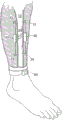
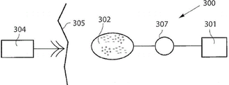
This situation is schematically depicted in fig. 4, which shows a fractured tibia (10) having a fractured zone (20) supported by two sets of means (40, 50) according to the invention, both attached to anchoring means (31, 32, 33, 34), said anchoring means (31, 32, 33, 34) being attached to the bone.
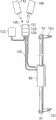
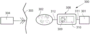
Figure 5 shows a detailed view of the distraction device, which in this figure is shown as a hydraulic device (80) with two actuators (91, 92), the two actuators (91, 92) being attached to two anchoring devices (101, 102) adapted to be embedded in the bone, the anchoring devices (101, 102) may be conventional pins or screws. The hydraulic device is in fluid contact with a hydraulic power unit (120) supplying pressurized hydraulic fluid through a tube (110), the hydraulic power unit (120) in turn being in communication with a control unit (130). Optionally, the control element also provides energy to the hydraulic power unit. The hydraulic power unit may comprise a reservoir and a pre-pressurized expansion reservoir of the pump or sampler type or any other hydraulic solution. The control unit, energy source, reservoir, pump or motor may all be implanted separately or together in any combination.
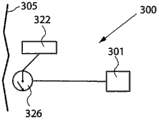
The power unit 120 may further be connected to or include a hydraulic pump 121 associated with a reservoir 122 containing a fluid, the hydraulic pump 121 being used to regulate the pressure of the device 80. The pump is thus adapted to pump hydraulic fluid into the device 80 or out of the device 80 to adjust the pressure in the device and the position of the actuators 91, 92.
The power unit 120 may also include a rechargeable battery 123 that may be externally charged by the external power supply/charging unit 112 that transmits wireless energy.
The adjustment may be controlled by an electronic remote control unit 124 adapted to receive and transmit signals from a transmitter/receiver 106 located outside the patient under treatment.
The hydraulic device preferably includes a device positioning system (e.g., fluid volume or flow measurement or any other sensor input) to view the position of the adjustment device. Preferably a sensor is provided which senses elongation (e.g. a capacitive sensor or an impedance sensor) or any sensor which senses motion or a particular position, here indicated as 125, i.e. a sensor which communicates with the control unit 124.
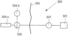
Alternatively, the schematic diagram of FIG. 5 may be shown instead as a mechanical device 80. In this case, the mechanical circuit, depicted as 110, is adapted to operate the mechanical device. The power unit 120 in this case may instead comprise a motor 121, a servo 123 and the preceding control unit 124 and sensors 125. The rechargeable power source may instead be identified by the unit 122. Of course, the motor may be placed directly in the mechanical unit 80, wherein the mechanical circuit 110 is replaced by an electrical wire.
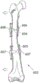
Fig. 6 shows an embodiment of the invention in which a set of devices is implanted in a bone (200) having two ends or epiphyses (201, 202) and a fracture region (206) which also constitutes a growth or elongation zone. The intramedullary canal (204) is schematically shown in partial section, in which a device (210) is arranged, which device (210) has actuators or anchoring tools (212, 214) acting on the ends of the intramedullary canal in order to achieve bone lengthening by osteogenesis in the fracture or elongation zone (206).
A detailed view of the device 210 according to various embodiments of the present invention is shown in fig. 7a and 7 b.
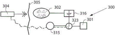
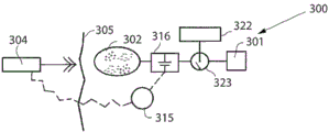
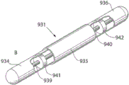
Figure 7a shows schematically an embodiment of a drafting element or device (300), the drafting element or device (300) comprising a housing (301) with an electric motor (302), the electric motor (302) acting on a threaded cylinder (303) engaged with two actuators (304, 305). Any mechanical solution may be used. The motor preferably employs a servo mechanism to substantially reduce the force. The control unit, energy source, motor or servo mechanism may be implanted separately or together in any combination.
Fig. 7b schematically shows another embodiment of the drafting element or device (400) comprising a housing (401) with two pistons (402, 403), which pistons (402, 403) are connected to two actuators (404, 405). The piston, together with the housing and possibly other additional elements, forms a hydraulic device which is connected to a hydraulic power unit (not shown) via a pipe (406).
The device according to the invention can also be applied for spinal curvature adjustment. Figures 8 a-8 c show an embodiment of the device according to the invention applied for spinal curvature adjustment. Detail (a) is a posterior side view of the lower back vertebrae (lumbar) schematically showing two sets of devices (501, 504) attached to either side of the spine according to the present invention. For illustrative purposes, one set of devices (501) is shown attached to two adjacent vertebrae by two sets of anchoring devices (502, 503) anchored in the vertebral body, while the other device (504) is shown attached to two non-adjacent vertebrae by two sets of anchoring devices (505, 506). Detail (b) is a side view schematically showing two sets of devices (510, 520) attached to both sides of the spinal column by anchoring devices (511, 512, 521, 522) according to the present invention. For demonstration purposes, one set of devices acts on adjacent vertebrae and the other set of devices acts on non-adjacent vertebrae. This embodiment can be used to adjust the curvature of the spine to alleviate lumbar disc herniation, and the like.
According to another embodiment, the force applied by the adjustment device is a longitudinal force, adjusting the angle or curvature of the bone. This is illustrated in fig. 9a, which schematically shows a front view of the right femur (600), the right femur (600) presenting the symptom of bending away from its natural shape. Flexion may be caused by congenital disease or other conditions. The dashed lines (601, 602) indicate how the bone may be fractured, preferably by sawing. As an example, the wedge is cut and the bone is divided into several parts, three shown in fig. 9 a. Fig. 9b shows how the three parts of the femur (603) are repositioned to the desired orientation (i.e. straight bone). The fracture zone (604, 605) then serves as a growth zone to compensate for the reduction in length due to the bone resection. Subsequently, a device (606, 607) according to the invention is attached to these parts by means of actuators and anchoring means, securing their position and applying a force to achieve osteogenesis elongation by distraction. These arrows schematically show that the bone parts can be adjusted relative to each other, for example by adjusting the angle or direction of the parts.
According to another embodiment, two or more anchoring devices are adapted to engage a cortical portion of the bone.
According to another embodiment, the two or more anchoring devices are adapted to engage the bone from within the intramedullary canal.
According to another embodiment, the at least two anchoring means are selected from pins, screws, glue, barb structures, serration structures, expansion elements, combinations thereof or other mechanical connection components.
According to a further embodiment, the force exerted by the adjustment device is a longitudinal force extending the length of the bone.
According to one embodiment, said force exerted by the adjustment device is directed towards the end of the marrow cavity.
According to one embodiment, said force exerted by the adjustment device is a longitudinal force, adjusting the angle or curvature of the bone.
According to one embodiment, said force applied by the device applies a torsional force to the bone, adjusting the torque of the bone along its longitudinal axis.
A related embodiment is shown in fig. 9c and 9d, where a deformed bone 600 is cut at two locations 601 and 602, each cut preferably being wedge-shaped to straighten the bone, and devices 610 and 620 according to the invention are embedded in the medullary cavity. These arrows schematically show that the parts of the bone may be adjusted relative to each other, e.g. by adjusting the angle or direction of the parts, similar to that shown in fig. 9 b.
According to yet another embodiment, the force applied by the device applies a torsional force to the bone, adjusting the torque of the bone along its longitudinal axis. This embodiment is shown in fig. 9e and 9f, where the bone 600 is cut along dashed line 630 and optionally along one or more lines (631 for example). One or more implantable devices 640 and 650 according to the present invention are embedded in the medullary cavity. These arrows indicate that one or more portions of the bone may be adjusted, e.g., rotated relative to the joint or rotated relative to a portion of the bone.
According to a further embodiment, which can be freely combined with any of the embodiments presented herein, the device is flexible for introduction into the bone marrow cavity.
According to one embodiment, the device is at least partially elastic.
According to one embodiment, the device comprises a spring.
According to one embodiment, the device resumes its shape after having been bent.
According to a further embodiment, which can be freely combined with any of the embodiments presented herein, said anchoring device is adapted to be adjustable by said adjustment device when implanted in the mammal body for engaging and fixing the anchoring device relative to the bone.
According to one embodiment, the anchoring device comprises a thread for engaging and fixing said anchoring device relative to the bone.
According to another embodiment, the anchoring device comprises an expandable portion which expands at least partially perpendicular to the longitudinal extension of the elongated device for engaging and fixing the anchoring device relative to the bone.
According to another embodiment, the adjustment device comprises hydraulic means for said bone adjustment to control the amount of force applied by the device to said anchoring means.
According to one embodiment, the hydraulic device comprises a cylinder and a piston.
The advantages of the flexible device are illustrated in fig. 12a-12d, which schematically show a bone 200 having a fracture zone I. Opening II is prepared by the surgeon to insert device III into bone marrow lumen IV. Fig. 12b shows how device III according to an embodiment of the invention is flexible and makes it possible to introduce the device into the marrow cavity through an opening that is not drawn straight longitudinally into the cavity. In addition, fig. 12c shows how the device III, when in place in the cavity IV, retains its original shape and expands longitudinally to apply a force towards the end of the cavity. The anchoring device functions and securely engages the surrounding bone. The opening II is preferably closed, for example with bone cement. Finally, FIG. 12d shows an embodiment where the device III is connected to a power unit V, which may have the components and functions of the power unit 120 shown in FIG. 5.
Fig. 11 shows a system for treating a disease comprising an appliance 301 according to an embodiment of the invention placed in the lower leg of a patient. The implantable energy transforming device 302 is adapted to power energy consuming components of the apparatus via a power supply line 303. An external energy transmission means 304 for non-invasively powering the appliance 301 transmits energy via at least one wireless energy signal. The implanted energy transforming device 302 transforms energy from the wireless energy signal into electric energy supplied via a supply line 303. Another external device 305 is shown schematically showing a device capable of sending control signals to appliance 301 and optionally receiving signals sent by appliance 301, such as for example relating to position, energy level, strain, pressure, temperature information or other relevant information recorded by one or more sensors (not shown) comprised in the appliance.
The wireless energy signal may comprise a wave signal selected from the group consisting of: acoustic wave signals, ultrasonic wave signals, electromagnetic wave signals, infrared light signals, visible light signals, ultraviolet light signals, laser signals, microwave signals, radio wave signals, X-ray radiation signals, and gamma radiation signals. Furthermore, the wireless energy signal may comprise an electric or magnetic field or a combined electromagnetic field.
The wireless energy transfer means 304 may transmit a carrier signal carrying the wireless energy signal. Such carrier signals may include digital signals, analog signals, or a combination of digital and analog signals. In this case, the wireless energy signal includes an analog signal or a digital signal or a combination of an analog signal and a digital signal.
Generally, the energy transforming device 302 is adapted to transform the wireless energy of the first form transmitted by the energy transmission device 304 into energy of a second form, which is generally different from the energy of the first form. The implantable appliance 301 may operate in response to the second form of energy. As the energy transforming device 302 transforms the energy of the first form transmitted by the energy transmission device 304 into the energy of the second form, the energy transforming device 302 may directly power the apparatus with the energy of the second form. The system may further comprise an implantable accumulator, wherein the energy of the second form is at least partially used for storing the accumulator.
Alternatively, as wireless energy is transmitted by the energy transmission device 304, the wireless energy transmitted by the energy transmission device 304 may be used to directly power the appliance. Where the system comprises operation means for operating the appliance, the wireless energy transmitted by the energy transmission means 304 may be used to directly power the operation means to generate the kinetic energy required for operating the apparatus, as will be described hereinafter.
The first form of wireless energy may comprise sound waves and the energy transforming device 302 may comprise a piezoelectric element for transforming the sound waves into electrical energy. The energy of the second form may comprise electrical energy in the form of direct current, or pulsating direct current, or a combination of direct and pulsating direct current, or alternating current, or a combination of direct and alternating current. Typically, the appliance includes electronic components that are energized by the electrical energy. Other implantable electronic components of the system may be at least one voltage level guard or at least one constant current guard connected to the electronic components of the instrument.
Alternatively, one of the first form of energy and the second form of energy may comprise magnetic energy, kinetic energy, acoustic energy, chemical energy, radiant energy, electromagnetic energy, optical energy, nuclear energy, or thermal energy. Preferably, one of the energy of the first form and the energy of the second form is non-magnetic, non-kinetic, non-chemical, non-acoustic, non-nuclear or non-thermal.
The energy transmission device is controllable from outside the patient's body to release electromagnetic wireless energy, and the released electromagnetic wireless energy is used to operate the apparatus. Alternatively, the energy transmission device may be controlled from outside the patient's body to release non-magnetic wireless energy, and the released non-magnetic wireless energy is used to operate the apparatus.
The external energy transmission device 304 further comprises: a wireless remote control having an external signal transmitter for transmitting wireless control signals to control the appliance in a non-invasive manner. The control signal is received by an implanted signal receiver, which may be integrated in the implanted energy transforming device 302 or separate from the implanted energy transforming device 302.
The wireless control signal may comprise a frequency modulated signal, an amplitude modulated signal, or a phase modulated signal, or a combination thereof. Alternatively, the wireless control signal comprises an analog signal or a digital signal or a combination of an analog signal and a digital signal. Alternatively, the wireless control signal comprises an electric field, a magnetic field, or a combined electromagnetic field.
The wireless remote controller can transmit a carrier signal carrying the wireless control signal. Such carrier signals may include digital signals, analog signals, or a combination of digital and analog signals. The wireless remote control preferably transmits an electromagnetic carrier signal carrying either the digital control signal or the analog control signal whenever the control signal comprises either the analog signal or the digital signal or a combination of the analog signal and the digital signal.
Fig. 14 shows in a more general block diagram the system as exemplified in fig. 4, 6, 12a-12d or 38, showing an implanted appliance 301, an energy transforming device 302 for energizing the appliance 301 via an energy supply line 303, and an external energy transmission device 304. The patient's skin 305 is shown generally as a vertical line separating the patient's body on the right side of the line from the body on the left side of the line.
FIGURE 15 shows an embodiment of the invention identical to that of FIGURE 14, except that an inverting device for inverting the instrument 301, for example in the form of an electrical switch 306 operable by means of polarised energy, is additionally implanted in the patient. When the switch is operated with polarized energy, the wireless remote control of the external energy transmission means 304 transmits a wireless signal carrying the polarized energy, and the implanted energy transforming means 302 transforms this wireless polarized energy into a polarized current for operating the electric switch 306. When the polarity of this current is switched by the implanted energy transforming device 302, the electrical switch 306 transforms the function performed by the appliance 301.
Fig. 16 shows an embodiment of the invention identical to that of fig. 14, except that an operating device 307 is arranged between the implantable energy transforming device 302 and the apparatus 301, which is implanted in the patient for operating the apparatus 301. This operating means may take the form of a motor 307, for example an electric servo motor. The motor 307 is supplied with energy from the implanted energy-transforming device 302 as a remote control of the external energy transmission device 304 transmits a wireless signal to the implanted energy-transforming device 302.
FIGURE 17 shows an embodiment of the invention identical to that of FIGURE 14, except that it also comprises an operation device implanted in the patient in the form of an assembly 308 comprising a motor/pump unit 309 and a liquid reservoir 310. In this case, the appliance 301 is hydraulically operated, i.e. hydraulic fluid is pumped by the motor/pump unit 309 from the reservoir 310 via a conduit 311 to the appliance 301 to operate the appliance, and the motor/pump unit 309 pumps hydraulic fluid from the appliance 301 back into the reservoir 310 to return the appliance to the starting position. The implantable energy transforming device 302 transforms the wireless energy into a current (e.g. a polarized current) for powering the motor/pump unit 309 via the power supply line 312.
It is also envisaged that the operation means may comprise a pneumatically operated device instead of the hydraulically operated device 301. In this case, the hydraulic fluid may be compressed air to be conditioned, while the reservoir is replaced by an air chamber.
In all of these embodiments, the energy conversion device 302 may comprise a rechargeable energy accumulator, such as a battery or capacitor, to be charged with wireless energy and to power energy consuming components of the system.
Alternatively, the wireless remote control described above may be replaced with any implanted component manual control, such as buttons placed under the skin, that would most likely be indirectly accessible to the patient's hand.
Fig. 18 shows an embodiment of the invention comprising an external energy transmission device 304 with its wireless remote control, an apparatus 301 (in this case hydraulically operated), and an implantable energy transforming device 302, and further comprising a hydraulic fluid reservoir 313, a motor/pump unit 309 and a reversing device in the form of a hydraulic valve shifting device 314, all implanted in the patient. Of course, the hydraulic valve may be omitted since the hydraulic operation can be easily performed only by changing the pumping direction. The remote control may be independent of the external energy transmission device or may be comprised in the external energy transmission device. The motor of the motor/pump unit 309 is an electric motor. In response to a control signal from the wireless remote control of the external energy transmission device 304, the implanted energy transforming device 302 supplies the motor/pump unit 309 with energy carried by the control signal, so that the motor/pump unit 309 distributes hydraulic fluid between the hydraulic fluid reservoir 313 and the appliance 301. The remote control of the external energy transmission means 304 controls the hydraulic valve switching means 314 to switch the hydraulic fluid flow direction between a direction in which liquid is pumped by the motor/pump unit 319 from the hydraulic fluid reservoir 313 to the appliance 301 for operating the appliance and a direction in which liquid is pumped by the motor/pump unit 309 back from the appliance 301 to the hydraulic fluid reservoir 313 for returning the appliance to the starting position.
Fig. 19 shows an embodiment of the invention comprising an external energy transmission apparatus 304 with its wireless remote control, an appliance 301, an implanted energy transforming device 302, an implanted internal control unit 315 controlled by the wireless remote control of the external energy transmission device 304, an implanted accumulator 316 and an implanted capacitor 317. The internal control unit 315 is arranged to store electrical energy received from the implanted energy transforming device 302 in an accumulator 316, the energy being supplied to the apparatus 301 by the accumulator 316. In response to a control signal from the wireless remote control of the external energy transmission device 304, the internal control unit 315 either releases electrical energy from the accumulator 316 and transmits the released energy via the power lines 318 and 319, or directly transmits electrical energy from the implanted energy transmission device 302 via the power line 320, the capacitor 317 for stabilizing the current, the power line 321 and the power line 319 for operating the appliance 301.
The internal control unit is preferably programmable from outside the patient's body. In a preferred embodiment, the internal control unit is programmed to adjust the appliance 301 according to a pre-programmed schedule, or according to input from any sensor sensing any possible physical parameter of the patient or any functional parameter of the system.
According to an alternative, the capacitor 317 in the embodiment of fig. 19 may be omitted. According to another alternative, the accumulator 316 in this embodiment may be omitted.
FIGURE 20 shows an embodiment of the invention identical to that of FIGURE 14, except that a battery 322 for supplying energy to operate the appliance 301 and an electrical switch 323 for switching the operation of the appliance 301 are additionally implanted in the patient. The electrical switch 323 is controllable by the remote control and also operates using the energy supplied by the implanted energy transforming device 302 to switch from an off mode, in which the batteries are not in use, to an on mode, in which the batteries 322 are powered for operating the appliance 301.
Fig. 21 shows an embodiment of the invention identical to that of fig. 20, except that an internal control unit 315 controllable by the wireless remote control of the external energy transmission device 304 is additionally implanted in the patient. In this case, the electrical switch 323 is operable with energy supplied by the implanted energy transforming device 302 to switch from an off mode, in which the wireless remote control is not able to control the internal control unit 315 and the battery is not in use, to a standby mode, in which the remote control is allowed to control the internal control unit 315 to release electrical energy from the battery 322 for operating the appliance 301.
Fig. 22 shows an embodiment of the invention identical to that of fig. 21, except that an accumulator 316 is used in place of the battery 322 and the implantable components are interconnected. In this case, the accumulator 316 stores energy from the implanted energy-transforming device 302. In response to a control signal from the wireless remote control of the external energy transmission means 304, the internal control unit 315 controls the electric switch 323 to switch from an off mode, in which the accumulator 316 is not in use, to an on mode, in which the accumulator 316 supplies energy for use in operating the appliance 301. The accumulator may be combined with or replaced by a capacitor.
FIGURE 23 shows an embodiment of the invention identical to that of FIGURE 22, except that a battery 322 is additionally implanted in the patient and the implantable components are interconnected. In response to a control signal from the wireless remote control of the external energy transmission means 304, the internal control unit 315 controls the accumulator 316 to deliver energy for operating the electric switch 323, switching from an off mode, in which the battery 322 is not in use, to an on mode, in which the battery 322 supplies electric energy for use in operating the appliance 301.
Alternatively, the electrical switch 323 is operable by energy supplied by the accumulator 316 to switch from an off mode, in which the wireless remote control is unable to control the battery 322 to supply electrical energy and the battery is not in use, to a standby mode, in which the wireless remote control is permitted to control the battery 322 to supply electrical energy for operating the appliance 301.
It should be understood that switch 323 and all other switches in the present application should be interpreted in their broadest implementation. This means a transistor, MCU, MCPU, ASIC, FPGA or DA converter or any other electronic component or circuit that can switch the power on and off. This switch is preferably controllable from outside the body, or alternatively by an implanted internal control unit.
According to one embodiment, the adjustment device comprises a mechanical device for the bone adjustment.
According to one embodiment, the adjustment means is operated by an operating means, such as a motor.
According to another embodiment, the device comprises a control device, wherein the operating device is controlled by the control device.
According to another embodiment, the motor includes a motor or device positioning system (e.g., tachometer or any other sensor input) to view the position of the adjustment device.
According to another embodiment, the mechanical means for said bone adjustment comprises at least one nut and screw.
According to another embodiment, the mechanical device for bone adjustment comprises at least one gearbox.
According to another embodiment, the mechanical means for bone adjustment comprises a servo mechanism or a mechanical amplifier.
According to another embodiment, the device is adapted to apply intermittent and/or oscillating forces.
FIGURE 24 shows an embodiment of the invention identical to that of FIGURE 20, except that a motor 307, a mechanical reversing device in the form of a gearbox 324 and an internal control unit 315 for controlling the gearbox 324 are additionally implanted in the patient. The internal control unit 315 controls the gearbox 324 to reverse the function performed by the appliance 301 (mechanical operation). A simpler way is to switch the motor direction electronically. The gearbox, as explained in its broadest embodiment, may represent a servo mechanism that reduces the force of the operating device in case of a long stroke.
This is also illustrated in fig. 39, which fig. 39 schematically shows a device according to an embodiment of the invention, wherein the implantable device 2000 comprises a motor 2010 operatively connected to a gearbox 2020 and to an adjustment device 2030, wherein the speed and/or effect of the motor 2010 is controlled by the control unit 2040.
According to one embodiment, the control unit 2040 may both sense the speed of the motor 2010 and adjust its speed, and optionally detect the output speed of the gearbox 2020 driving the adjustment device 2030. According to another embodiment, the control unit 2040 comprises a feedback loop that detects the speed of the motor and adjusts it to a desired value. In another embodiment, there is no gearbox and the control unit 2040 both detects the speed of the motor and adjusts its speed.
Fig. 25 shows an embodiment of the invention identical to that of fig. 23 (except for the interconnection of the implantable components). Accordingly, in this case, the internal control unit 315 is powered by the battery 322 when the accumulator 316 (and, where appropriate, a capacitor) triggers the electrical switch 323 to switch to the on mode. When the electrical switch 323 is in its on mode, the internal control unit 315 is allowed to control the battery 322 to supply or not supply energy for use in operating the appliance 301.
Fig. 26 schematically shows possible combinations of implantable components of an apparatus for implementing various communication options. Basically, there is an appliance 301, an internal control unit 315, a motor or pump unit 309 and an external energy transmission device 304 comprising an external wireless remote control. As already described above, the control signals transmitted by the wireless remote control are received by the internal control unit 315, and the internal control unit 315 in turn controls the various implantable components of the appliance.
The feedback device preferably includes a sensor or measurement device 325 implantable in the patient for sensing a physical parameter of the patient. The physical parameter may be at least one parameter selected from the group consisting of pressure, volume, diameter, stretch, elongation, movement, curvature, elasticity, muscle contraction, nerve impulse, body temperature, blood pressure, blood flow, heart beat, and respiration. The sensor may sense any of the physical parameters described above. For example, the sensor may be a pressure sensor or a motion sensor. Alternatively, the sensor 325 may be configured to detect a functional parameter. The functional parameter may relate to the transfer of energy to be stored in the implantable energy source and may further comprise at least one parameter selected from the group consisting of electrical power, pressure, volume, diameter, expansion, contraction, elongation, movement, flexion, elasticity, temperature and flow.
These feedback information may be sent to the internal control unit or sent externally (preferably via the internal control unit) to the external control unit. The feedback information may be sent from within the body via an energy transmission system or a separate communication system with a receiver and transmitter.
The internal control unit 315 (or alternatively an external wireless remote control of the external energy transmission device 304) may control the appliance 301 in response to signals from the sensor 325. The transceiver may transmit the detected physical parameter information to an external wireless remote control in combination with the sensor 325. The wireless remote control may comprise a signal transmitter or transceiver and the internal control unit 315 may comprise a signal receiver or transceiver. Alternatively, the wireless remote control may comprise a signal receiver or transceiver, and the internal control unit 315 may comprise a signal transmitter or transceiver. The transceivers, transmitters and receivers described above may be used to transmit information or data related to the appliance 301 from inside the patient's body to outside the patient's body.
In the case where the motor/pump unit 309 and the battery 322 for supplying power to the motor/pump unit 309 are implanted, information regarding the charging of the battery 322 can be fed back. For greater accuracy, when charging a battery or an energy storage device, feedback information is transmitted about the charging process and the energy supply is changed accordingly.
Fig. 27 shows an alternative embodiment in which the appliance 301 is adjusted from outside the patient's body. The system 300 includes a battery 322 connected to the appliance 301 via a subcutaneous electrical switch 326. Accordingly, non-invasive adjustment of the appliance 301 may be accomplished by manually depressing a subcutaneous switch thereby turning the appliance 301 on and off. It will be appreciated that the illustrated embodiment is somewhat simplified and that in fact additional components such as an internal control unit or any other accessory disclosed in this document may be added to the system. Two subcutaneous switches may also be used. In a preferred embodiment, an implanted switch sends information to the internal control unit to perform some predetermined function, and when the patient again presses the switch, the function is reversed.
Fig. 28 shows an alternative embodiment, in which the system 300 comprises a hydraulic fluid reservoir 313 hydraulically connected to the appliance. The non-invasive adjustment is performed by manually pressing a hydraulic reservoir connected to the appliance.
The system can include an external data communicator and an implantable internal data communicator communicating with the external data communicator. The internal communicator feeds back data related to the appliance or patient to the external data communicator and/or the external data communicator feeds back data to the internal data communicator.
Fig. 29 schematically shows a system configuration capable of sending information from inside the patient's body to outside the body to give feedback information about at least one functional parameter of the appliance or system or about a physical parameter of the patient, so as to supply a precise amount of energy to an implanted internal energy receiver 302 connected to an implanted energy consuming component of the appliance 301. Such an energy receiver 302 may comprise an energy source and/or an energy conversion device. Briefly, wireless energy is transmitted from an external energy source 304a located outside the patient's body and received by an internal energy receiver 302 located inside the patient's body. The internal energy receiver is adapted to supply the received energy directly or indirectly to energy consuming components of the appliance 301. An energy balance is determined between the energy received by the internal energy receiver 302 and the energy used by the appliance 301, and the wireless energy transmission is then controlled based on the determined energy balance. Thus, the energy balance provides an accurate indication of the exact amount of energy required to properly operate the appliance 301 without excessive temperature rise.
In fig. 29, the patient's skin is marked by vertical line 305. Here, the energy receiver comprises an energy transforming device 302 located inside the patient's body, preferably just below the patient's skin 305. In general, the implantable energy conversion device 302 may be subcutaneously implanted in the abdomen, chest, muscle fascia (e.g., in the abdominal wall), or any other suitable location. The implantable energy transforming device 302 is adapted to receive wireless energy E emitted by an external energy source 304a arranged in the external energy transmission device 304, the external energy transmission device 304 being located outside the skin 305 of the patient near the implantable energy transforming device 302.
As is well known in the art, the wireless energy E is typically transmitted by means of any suitable Transcutaneous Energy Transfer (TET) device, for example comprising a primary coil arranged in the external energy source 304a and an adjacent secondary coil arranged in the implantable energy transmission device 302. When current is supplied through the primary coil, energy in the form of voltage is induced in the secondary coil, which can be used (e.g., after storing the received energy in an implanted power supply such as a rechargeable battery or capacitor) to power energy consuming components of the appliance. However, the present invention is not generally limited to any particular energy transmission technology, TET device, or energy source, and may employ any type of wireless energy.
The amount of energy received by the implanted receiver may be compared to the energy used by the implanted components of the apparatus. Thus, by "used energy" is understood to also include energy stored by an implanted component of the apparatus. The control device comprises an external control unit 304b for controlling the external source of energy 304a to adjust the amount of energy transmitted, based on the determined energy balance. To deliver the correct amount of energy, the energy balance and the required amount of energy are determined by means of a determination means comprising an implanted internal control unit 315 connected to the apparatus 301. Thus, the internal control unit 315 may be arranged to receive various measurements taken by suitable sensors or similar devices (not shown) that measure certain characteristics of the appliance 301, which measurements in some way reflect the amount of energy required to operate the appliance 301 properly. In addition, the current condition of the patient may also be detected by means of a suitable measuring device or sensor to provide a parameter reflecting the patient's condition. Accordingly, these characteristics and/or parameters may be related to the current state of the appliance 301 (e.g., power consumption, operating mode and temperature, and patient condition as reflected by parameters such as body temperature, blood pressure, heart beat and respiration). Other types of physical parameters of the patient and other types of functional parameters of the device are described elsewhere herein.
Furthermore, an energy source in the form of an accumulator 316 may optionally be connected to the implanted energy transforming device 302 for accumulating the received energy for subsequent use by the apparatus 301. Alternatively or additionally, the properties of such an energy store (which also reflects the amount of energy required) can also be measured. The accumulator may instead be a rechargeable battery and the measured characteristic may be related to the current state of the battery, an electrical parameter such as the consumption voltage, the temperature, etc. It is clear that in order to provide sufficient voltage and current to the appliance 301 and to avoid overheating, charging in an optimal manner should be achieved by receiving an accurate amount of energy, i.e. neither too little nor too much energy, from the implanted energy-transforming device 302. The energy accumulator may also be a capacitor with corresponding characteristics.
For example, battery characteristics may be measured periodically to determine the current state of the battery, which may then be stored as state information in a suitable storage means in the internal control unit 315. In this way, the stored battery state information can be updated accordingly whenever a new measurement is made. In this way, the state of the battery can be "calibrated" by delivering an accurate amount of energy to maintain the battery in an optimal state.
Thus, the internal control unit 315 of the determination means is adapted to determine the energy balance and/or the currently required amount of energy (energy per time unit or accumulated energy) based on measurements made by the above-mentioned sensors or measurement means on the appliance 301, or the patient, or the implanted source of energy (if used), or a combination of the above three. The internal control unit 315 is further connected to an internal signal transmitter 327, the internal signal transmitter 327 being arranged to transmit a control signal reflecting the determined amount of required energy to an external signal receiver 304c connected to the external control unit 304 b. The amount of energy emitted from the external energy source 304a may then be adjusted in response to the received control signal.
Alternatively, the assay device may comprise an external control unit 304 b. In this alternative, the sensor measurements may be transmitted directly to the external control unit 304b, the energy balance and/or the currently required amount of energy being determined by the external control unit 304b, thereby integrating the above-described functions of the internal control unit 315 in the external control unit 304 b. In this case, the internal control unit 315 may be omitted and the sensor measurement results provided directly to the internal signal transmitter 327, which is transmitted by the internal signal transmitter 327 to the external signal receiver 304c and the external control unit 304 b. The energy balance and the current amount of energy required can then be determined by the external control unit 304b based on this sensor measurement.
Thus, the present solution according to the arrangement of fig. 25, which utilizes feedback of information indicative of the energy required, is more efficient than previous solutions, since it is based on actual energy usage compared to the received energy (e.g. amount of energy, energy difference, or energy reception rate compared to the energy rate used by implanted energy consuming components of the appliance). The received energy may be consumed by the apparatus or stored in an implanted source of energy or the like. Thus, if relevant or desired, the different parameters discussed above are used and used as a tool for determining the actual energy balance. However, these parameters may also be required by any action performed internally to specifically operate the appliance itself.
The internal signal transmitter 327 and the external signal receiver 304c may be implemented as separate units using suitable signal transmission means, such as radio signals, infrared signals or ultrasonic signals. Alternatively, the internal signal transmitter 327 and the external signal receiver 304c may be integrated in the implanted energy transforming device 302 and the external energy source 304a, respectively, for delivering the control signal in the opposite direction to the energy transmission (substantially using the same transmission technique). These control signals may be modulated in frequency, phase or amplitude.
Thus, the feedback information may be transmitted by a separate communication system including a receiver and a transmitter, or may be integrated in the energy system. According to the present invention, the integrated information feedback and energy system comprises: an implantable internal energy receiver for receiving wireless energy, the energy receiver having an internal first coil and first electronic circuitry connected to the first coil; and an external energy transmitter for transmitting wireless energy, the energy transmitter having an external second coil and a second electronic circuit connected to the second coil. An external second coil of the energy transmitter transmits wireless energy received by the first coil of the energy receiver. The system further comprises a power switch for switching the connection of the internal first coil to the first electronic circuit, such that feedback information (in the form of impedance variations in the load of the external second coil) relating to the charging of the first coil is received by the external energy transmitter when the power switch switches the connection of the internal first coil to the first electronic circuit. When the system is implemented in the configuration of fig. 29, the switch 326 is either separate but controlled by the internal control unit 315, or integrated in the internal control unit 315. It should be understood that switch 326 should be construed in accordance with its broadest embodiment. This means a transistor, MCU, MCPU, ASIC FPGA or DA converter or any other electronic component or circuit that can switch the power on and off.
In summary, the energy source configuration shown in fig. 29 can operate substantially as follows. The energy balance is first determined by the internal control unit 315 of the determination device. A control signal reflecting the required amount of energy is also created by the internal control unit 315, which is transmitted from the internal signal transmitter 327 to the external signal receiver 304 c. Alternatively, the energy balance may be determined by the external control unit 304b rather than relying on an embodiment as described above. In this case, the control signal may carry measurements from various sensors. The amount of energy emitted by the external energy source 304a may then be adjusted by the external control unit 304b (e.g., in response to the received control signal) based on the determined energy balance. This process may be repeated intermittently at specific intervals during the energy transfer or may be performed substantially continuously during the energy transfer.
The amount of energy transferred is generally regulated by adjusting various transfer parameters (e.g., voltage, current, amplitude, wave frequency, and pulse characteristics) in the external energy source 304 a.
The system can also be used to obtain information about the coupling factor between coils in a TET system and even to calibrate the system to both find the best position for the outer coil relative to the inner coil and optimize energy transfer. The amount of transmitted energy in this case is simply compared with the amount of received energy. For example, the coupling factor may change if the external coil moves, and the correctly displayed motion may cause the external coil to find the best position for energy transfer. Preferably, the external coil is adapted to correct the amount of transmitted energy before the coupling factor is maximized to obtain feedback information in the assay device.
These coupling factor information can also be used as feedback information for the energy transfer process. In this case, the inventive energy system comprises an implanted internal energy receiver for receiving wireless energy, the energy receiver having an internal first coil and a first electronic circuit connected to the first coil, and an external energy transmitter having an external second coil and a second electronic circuit connected to the second coil. An external second coil of the energy transmitter transmits wireless energy received by the first coil of the energy receiver. The system further comprises feedback means for transferring the amount of energy received by the first coil out as feedback information, wherein the second electronic circuit comprises determination means for receiving the feedback information and comparing the amount of energy transferred by the second coil with the feedback information related to the amount of energy received in the first coil to obtain the coupling factor between the first coil and the second coil. The energy transmitted may be adjusted in accordance with the coupling factor obtained.
Referring to fig. 30, while the operation of the instrument with wireless energy transmission has been described above for non-invasive operation, it will be appreciated that the instrument may be operated using wire-bound energy. An example of this is shown in fig. 30, where an external switch 326 is connected between the external energy source 304a and an operating device, such as an electric motor 307, for operating the appliance 301. External control unit 304b controls the operation of external switch 326 to enable normal operation of appliance 301.
Fig. 31 shows different embodiments of how the received energy may be provided to and used by appliance 301. Similar to the example of fig. 29, the internal energy receiver 302 receives wireless energy E from an external energy source 304a controlled by a transmission control unit 304 b. The internal energy receiver 302 may comprise a constant voltage circuit, indicated in the figure by the dashed box "constant V", for supplying energy to the appliance 301 at a constant voltage. The internal energy receiver 302 may further comprise a constant current circuit, indicated in the figure by the dashed box "constant C", for supplying the appliance 301 with energy at a constant current.
The appliance 301 comprises an energy consuming accessory 301a, which may be a motor, a pump, a restriction device or any other medical device requiring energy for its electrical operation. The appliance 301 may further comprise an energy storage device 301b for storing energy supplied from the internal energy receiver 302. Thus, the supplied energy may be consumed directly by the energy consuming accessory 301a or stored by the energy storage device 301b, or the supplied energy may be partially used for the consumed portion for storage. The appliance 301 may further comprise an energy stabilizing unit 301c for stabilizing the energy supplied from the internal energy receiver 302. Accordingly, the energy may be supplied in a fluctuating manner, requiring that it be stabilized before it is consumed or stored.
The energy supplied from the internal energy receiver 302 may further be accumulated and/or stabilized by a separate energy stabilizing unit 328 located outside the appliance 301 before being consumed and/or stored by the appliance 301. Alternatively, the energy stabilizing unit 328 may be integrated in the internal energy receiver 302. In either case, the energy stabilization unit 328 may include a constant voltage circuit and/or a constant current circuit.
It should be noted that fig. 29 and 31 show some possible but not limiting embodiment options relating to how the various illustrated functional components and elements may be arranged and interconnected. However, the skilled person will understand that various changes and modifications may be made within the scope of the present invention.
Fig. 32 schematically shows an energy balance measuring circuit of one of the proposed designs of a system for controlling wireless energy transfer (or, an energy balance control system). The circuit has an output signal centered at 2.5V and proportionally related to the energy imbalance. The derivative of this signal indicates whether the value has risen or fallen and how fast the change has proceeded. If the amount of energy received is lower than the energy used by the implant, more energy is transmitted and correspondingly stored in the energy source. The output signals from the circuits are typically supplied to an a/D converter and converted to a digital format. The digital information may then be sent to an external energy transmission device for it to adjust the level of energy transmitted. Another possibility is to have a fully analog system that uses a comparator to compare the energy balance level with a certain maximum or minimum threshold and sends information to the external energy transmission device when the balance shifts out of the maximum/minimum window.
Circuit schematic diagram fig. 32 shows a circuit implementation of a system for transferring energy from outside the patient's body to the implanted energy component of the apparatus of the invention using inductive energy transfer. Inductive energy transfer systems typically use an external transmitter coil and an internal receiver coil. A receive coil, L1, contained in the circuit schematic; while the transmit part of the system is excluded.
Of course, the implementation of the conventional concept of energy balancing and the way in which information is transmitted to the external energy transmitter can be implemented in several different ways. The schematic diagram of the circuit diagram of fig. 28 and the method of evaluating and transmitting information described above should be viewed only as an example of how the control system may be implemented.
Detailed description of the invention
In fig. 32, symbols Y1, Y2, Y3, and the like symbolize test points in the circuit. The components in the figures and their respective values are values for this particular embodiment, which is of course only one example of an infinite number of possible designs.
The energy supplied to this circuit is received by an energy receiving coil L1. In this particular case, the energy supplied to the implantable component is transmitted at a frequency of 25 kilohertz. An energy balanced output signal is present at test point Y1.
Those skilled in the art will appreciate that the various embodiments of the system described above may be combined in different ways. For example, the electrical switch of fig. 11 may be integrated into any of the embodiments of fig. 14-20, the hydraulic valve switching device 314 may be integrated into another embodiment of the invention, and the gearbox 324 may be integrated into yet another embodiment.
Note that this switch can only represent any electronic circuit or component.
The embodiments described in connection with fig. 29, 31 and 32 define a method and system for controlling the transfer of wireless energy to energy consuming components of an electrically operable appliance. The method and system are generally defined below.
Accordingly, a method of controlling the transmission of wireless energy supplied to an implanted energy consuming component of an apparatus as described above is provided. The wireless energy E is emitted from an external energy source located outside the patient's body and is received by an internal energy receiver located inside the patient's body, which internal energy receiver is connected to the implanted energy consuming part of the appliance to supply the received energy directly or indirectly to the energy consuming part of the appliance. An energy balance between the energy received by the internal energy receiver and the energy used by the appliance is determined. The emission of wireless energy E from the external energy source is then controlled in accordance with the determined energy balance.
The wireless energy may be inductively transferred from a primary coil in the external energy source to a secondary coil in the internal energy receiver. A change in energy balance may be detected, thereby controlling the wireless energy transfer based on the detected energy balance change. The difference between the energy received by the internal energy receiver and the energy used by the medical device may also be detected, thereby controlling the wireless energy transmission based on the detected energy difference.
When controlling the energy transfer, the amount of wireless energy transfer is decreased if the detected energy balance change indicates an increasing energy balance and vice versa. The decrease/increase in energy transfer may further correspond to the detected rate of change.
If the detected energy difference indicates that the received energy is greater than the used energy, the amount of transmitted wireless energy may be further reduced, and vice versa. Accordingly, the decrease/increase in energy transfer may correspond to the magnitude of the detected energy difference.
As described above, the energy used by the medical device may be consumed for operating the medical device and/or stored in at least one energy storage device of the medical device.
In determining the electrical and/or physical parameters of the medical device and/or the physical parameters of the patient, the energy for consumption and storage can be transmitted in accordance with the transmission rate per unit time determined on the basis of said parameters. The total amount of energy transferred can also be determined based on said parameters.
When a difference between the total energy received by the internal energy receiver and the total energy consumed and/or stored is detected, and the detected difference relates to a time integral of at least one measured electrical parameter related to the energy balance, the integral may be determined with respect to the monitored voltage and/or current related to the energy balance.
When determining the time derivative of the measured electrical parameter related to the amount of total energy consumed and/or stored, the derivative may be determined with respect to the monitored voltage and/or current related to the energy balance.
The transmission of wireless energy from an external energy source may be controlled in the following manner: applying an electrical pulse from a first electronic circuit to the external energy source to transmit wireless energy, the electrical pulse having a leading edge and a trailing edge; varying the length of a first time interval between a leading edge of an electrical pulse and a subsequent trailing edge and/or the length of a second time interval between a trailing edge of an electrical pulse and a subsequent leading edge; and transmitting wireless energy, the power of the transmitted energy generated by the electrical pulses being variable, the power varying depending on the length of the first time interval and/or the second time interval.
In this case, the frequency of the electrical pulses may be substantially constant when the first time interval and/or the second time interval is varied. When applying the electrical pulse, the electrical pulse may remain unchanged (except for the first time interval and/or the second time interval changing). The amplitude of the electrical pulse may be substantially constant as the first time interval and/or the second time interval is varied. Furthermore, the electrical pulse may be varied by varying only the length of the first time interval between the leading edge of the electrical pulse and the subsequent trailing edge.
Two or more electrical pulses may be supplied in a train, wherein the train has a first electrical pulse at the beginning of the train and a second electrical pulse at the end of the train when the train is applied, and two or more trains may be supplied in a train, wherein the length of a second time interval between a trailing edge of a second electrical pulse of a first train and a leading edge of a first electrical pulse of a subsequent second train varies.
The electrical pulse may have a substantially constant current and a substantially constant voltage when applied. The electrical pulses may also have a substantially constant current and a substantially constant voltage. Furthermore, the electrical pulses may also have a substantially constant frequency. The electrical pulses in the pulse train may likewise have a substantially constant frequency.
The circuit formed by the first electronic circuit and the external energy source may have a first characteristic time period or a first time constant, and this frequency time period may be within the range of the first characteristic time period or the time constant or shorter while the transmission energy is effectively changed.
Thus, a system comprising an apparatus as described above is also used for controlling the transmission of wireless energy supplied to implanted energy consuming components of the apparatus. In its broadest sense, the system comprises a control device for controlling the wireless energy transmission from the energy transmission device and an implanted internal energy receiver for receiving the transmitted wireless energy, the internal energy receiver being connected to an implanted energy consuming component of the apparatus for directly or indirectly supplying the received energy to the energy consuming component of the apparatus. The system further comprises a determination device adapted to determine an energy balance between the energy received by the internal energy receiver and the energy used by the implanted energy consuming components of the apparatus, wherein the control device controls the wireless energy transmission from the external energy transmission device based on the energy balance determined by the determination device.
Further, the system may include any of:
-a primary coil in the external energy source adapted to inductively transfer wireless energy to a secondary coil in the internal energy receiver.
The determination means are adapted to detect a change in energy balance and the control means control the wireless energy transfer based on the detected change in energy balance.
The determination means are adapted to detect a difference between the energy received by the internal energy receiver and the energy used by the implantable energy consuming components of the apparatus, and the control means control the wireless energy transmission based on the detected energy difference.
-if the detected change in energy balance indicates an increasing energy balance, the control device controls the external energy transmission device to decrease the amount of wireless energy transmission, and vice versa, wherein the decrease/increase in energy transmission corresponds to the detected rate of change.
-if the detected energy difference indicates that the received energy is greater than the used energy, the control device controls the external energy transmission device to decrease the amount of wireless energy transmission, and vice versa, wherein the decrease/increase of energy transmission corresponds to the magnitude of the detected energy difference.
The energy used by the appliance is consumed for operating the appliance and/or is stored in at least one energy storage device of the appliance.
In the case of the determination of an electrical and/or physical parameter of the appliance and/or of a physical parameter of the patient, the energy transmission device transmits the energy for consumption and storage in accordance with the transmission rate per unit time determined by the determination device on the basis of said parameter. The determining means also determines the total amount of energy transferred based on the parameter.
-the determination means determine an integral of the monitored voltage and/or current related to the energy balance when a difference between the total energy received by the internal energy receiver and the total energy consumed and/or stored is detected and the detected difference is related to a time integral of at least one measured electrical parameter related to said energy balance.
When determining the time derivative of the measured electrical parameter with respect to the amount of consumed and/or stored energy, the determining means determines the derivative with respect to the monitored voltage and/or current with respect to the energy balance.
The energy transmission device comprises a coil placed outside the human body and an electronic circuit for supplying the external coil with electrical pulses for transmitting wireless energy. The electrical pulse has a leading edge and a trailing edge, and the electronic circuitry is adapted to vary a first time interval between the leading edge of the electrical pulse and the subsequent trailing edge and/or a second time interval between the trailing edge of the electrical pulse and the subsequent leading edge to vary the power of the transmitted wireless energy. The result is that the power of the energy receiver receiving the transmitted wireless energy is varied.
The electronic circuit is adapted to keep the electrical pulses unchanged except for changing the first time interval and/or the second time interval.
The electronic circuit has a time constant and is adapted to vary the first time interval and the second time interval only within the range of the first time constant, so that the power emitted by the coil varies as the length of the first time interval and/or the second time interval varies.
The electronic circuit is adapted to cause the electrical pulse to change only by changing the length of the first time interval between the leading edge of the electrical pulse and the trailing edge of the subsequent electrical pulse.
The electronic circuit is adapted to supply a train of two or more electrical pulses in a train, the train having a first electrical pulse at the beginning of the train and a second electrical pulse at the end of the train, and
the first electronic circuit varies the length of a second time interval between the trailing edge of a second electrical pulse of the first pulse train and the leading edge of a first electrical pulse of the second pulse train consecutive thereto.
The electronic circuit is adapted to set said electric pulses as pulses having a substantially constant height and/or amplitude and/or intensity and/or voltage and/or current and/or frequency.
The electronic circuit has a time constant and is adapted to vary the first time interval and the second time interval only within the range of the first time constant, so that the power emitted via the first coil varies as the length of the first time interval and/or the second time interval varies.
The electronic circuit is adapted to configure the electrical pulses such that the length of the first time interval and/or the second time interval varies only within a range including the first time constant or being located relatively close to the first time constant compared to the magnitude of the first time constant.
According to one embodiment, the wireless energy signal comprises a wave signal selected from the group consisting of: acoustic wave signals, ultrasonic wave signals, electromagnetic wave signals, infrared light signals, visible light signals, ultraviolet light signals, laser signals, microwave signals, radio wave signals, X-ray radiation signals, and gamma radiation signals.
According to one embodiment, the wireless energy comprises one of: electric field, magnetic field, combined electromagnetic field.
According to one embodiment, the control signal comprises one of: electric field, magnetic field, combined electromagnetic field.
According to a further embodiment, the signal comprises an analog signal, a digital signal, or a combination of an analog signal and a digital signal.
According to yet another embodiment, the system further comprises an implantable internal energy source for powering an implantable energy consuming component of the apparatus.
According to a further embodiment, the system further comprises an external energy source for transmitting energy in the wireless mode, wherein the energy transmitted in the wireless mode is storable into the internal energy source.
According to a further embodiment, the system further comprises a sensor or measuring device for detecting or measuring a functional parameter related to the transmission of energy for storing the internal source of energy and a feedback device for transmitting feedback information from inside the patient's body to outside the patient's body, the feedback information being related to the functional parameter detected by the sensor or measured by the measuring device.
According to a further embodiment, the system further comprises feedback means for transmitting feedback information from inside the patient's body to outside the patient's body, the feedback information being related to a physical parameter of the patient and/or a functional parameter related to the appliance.
According to yet another embodiment, the system further comprises a sensor and/or a measuring device and an implantable internal control unit for controlling the appliance in response to information related to a physical parameter of the patient detected by the sensor or measured by the measuring device and/or a functional parameter related to the appliance detected by the sensor or measured by the measuring device.
According to another embodiment, the physical parameter is pressure or motility movement.
According to yet another embodiment, the system further comprises an external data communicator and an implantable internal data communicator communicating with the external data communicator, wherein the internal communicator feeds back data related to the appliance or the patient to the external data communicator and/or the external data communicator feeds back data to the internal data communicator.
According to yet another embodiment, the system further comprises a motor or pump for operating the appliance.
According to yet another embodiment, the system further comprises a hydraulic operation device for operating the appliance.
According to a further embodiment, the system further comprises an operating device for operating the appliance, wherein the operating device comprises a servo mechanism designed to reduce the force required by the operating device to operate the appliance, instead of the operating device acting in a more permanent manner (increasing the time for the determined action).
According to another embodiment, the system further comprises an operation device for operating the appliance, wherein, as wireless energy is transmitted by the energy transmission device, the wireless energy directly powers the operation device in its wireless state to generate kinetic energy for operation of the appliance.
According to yet another embodiment, the system further comprises an energy transforming device for transforming the wireless energy transmitted by the energy transmission device from a first form into energy of a second form.
According to an embodiment, the energy transforming device directly powers implantable energy consuming components of the apparatus with the energy of the second form as the energy transforming device transforms the energy of the first form transmitted by the energy transmission device into the energy of the second form.
According to one embodiment, the energy of the second form comprises at least one of direct current, pulsating direct current and alternating current.
According to yet another embodiment, the system further comprises an implantable accumulator, wherein the energy of the second form is at least partly used for accumulating in the accumulator.
According to an embodiment, the first form of energy or the second form of energy comprises at least one of magnetic energy, kinetic energy, acoustic energy, chemical energy, radiant energy, electromagnetic energy, optical energy, nuclear energy, thermal energy, non-magnetic energy, non-kinetic energy, non-chemical energy, non-acoustic energy, non-nuclear energy or non-thermal energy.
According to yet another embodiment, the system further comprises implantable electronic components including at least one voltage level guard and/or at least one constant current guard.
According to yet another embodiment, the system further comprises a control device for controlling the wireless energy transmission from the energy transmission device and an implantable internal energy receiver for receiving the transmitted wireless energy, the internal energy receiver being connected to implantable energy consuming components of the apparatus for directly or indirectly supplying the received energy to the energy consuming components of the apparatus. The system further comprises a determination device adapted to determine an energy balance between the energy received by the internal energy receiver and the energy used by implantable energy consuming components of the apparatus, wherein the control device controls the wireless energy transmission from the external energy transmission device based on the energy balance determined by the determination device.
According to one embodiment, the determination means are adapted to detect a change in energy balance, and the control means control the wireless energy transfer based on the detected change in energy balance.
According to another embodiment, the determination means are adapted to detect a difference between the energy received by the internal energy receiver and the energy used by the implantable energy consuming components of the apparatus, and the control means control the transmission of wireless energy based on the detected energy difference.
According to another embodiment, the energy transmission device comprises a coil placed outside the human body, the energy transmission device further comprising an implantable energy receiver placed inside the human body and an electronic circuit connected to supply the external coil with electrical pulses for transmitting wireless energy, the electrical pulses having a leading edge and a trailing edge, and the electronic circuit being adapted to vary a first time interval between the leading edge of an electrical pulse and a subsequent trailing edge and/or a second time interval between the trailing edge of an electrical pulse and a subsequent leading edge for varying the power of the transmitted wireless energy, the power of the energy receiver receiving the transmitted wireless energy being varied.
According to a further embodiment, the electronic circuit is adapted to keep the electrical pulses unchanged except for changing the first time interval and/or the second time interval.
According to another embodiment, the electronic circuit has a time constant and is adapted to vary the first time interval and the second time interval only within the range of the first time constant, so that the power emitted by the coil varies as the length of the first time interval and/or the second time interval varies.
According to another embodiment, the system comprises an implantable internal energy receiver for receiving wireless energy, the energy receiver having an internal first coil and first electronic circuitry connected to the first coil; and an external energy transmitter for transmitting wireless energy, the energy transmitter having an external second coil and a second electronic circuit connected to the second coil, wherein the external second coil of the energy transmitter transmits wireless energy received by the first coil of the energy receiver, the system further comprising a power switch for switching the connection of the internal first coil to the first electronic circuit, such that feedback information related to the charging of the first coil (in the form of impedance changes in the load of the external second coil) is received by the external energy transmitter when the power switch switches the connection of the internal first coil to the first electronic circuit.
According to another embodiment, the system comprises an implantable internal energy receiver for receiving wireless energy and an external energy transmitter for transmitting wireless energy, the energy receiver has an internal first coil and a first electronic circuit connected to the first coil, and the energy transmitter has an external second coil and a second electronic circuit connected to the second coil, wherein the outer second coil of the energy transmitter transmits wireless energy received by the first coil of the energy receiver, the system further comprises feedback means for transferring the amount of energy received by the first coil out as feedback information, wherein the second electronic circuit comprises determination means for receiving the feedback information and comparing the amount of energy transferred by the second coil with the feedback information related to the amount of energy received in the first coil to obtain the coupling factor between the first coil and the second coil.
According to one embodiment, the transmitted energy may be adjusted according to the obtained coupling factor.
According to another embodiment, the outer second coil is adapted to be moved relative to the inner first coil to establish an optimal position of the second coil for maximizing the coupling factor.
According to another embodiment, said external second coil is adapted to calibrate the amount of energy transferred before the coupling factor is maximized to obtain feedback information in the assay device.
According to a further embodiment, the mechanical device comprises a mechanical multi-step locking mechanism for locking the adjusted mechanical device in its new position. An example is illustrated in fig. 10a and 10b, where fig. 10a schematically shows a detail of a device (700) according to the invention, comprising at least one hydraulic piston (701) and two actuators (702, 703). In this embodiment, one actuator is attached to the housing of the device, while the other actuator is movable. To prevent the actuator (e.g., when temporarily subjected to increased pressure) from returning to a previous position, the housing has an aperture (705) and the actuator has a tapered flange (704) that allows outward movement and substantially does not allow inward movement.
Fig. 10b shows an alternative embodiment, wherein in the device (800) according to the invention two pistons (801, 802) are arranged in the housing. These pistons are connected to two actuators (805, 806) which in turn engage with anchoring means (not shown). The interior of the housing has a pattern of protrusions, bands or barbs that allow the piston to move in one direction (preferably outward) and substantially not allow inward movement thereof.
According to yet another embodiment, the mechanical multi-step locking mechanism comprises at least one of a short distance piece, an elongated structure using the saw tooth, flange, barb or cover tape principle, a nut, a gearbox or a loaded spring of the locking principle.
According to another embodiment of the system, the device comprises a control device.
According to another embodiment, the control device follows a program of incremental changes that have been made before the device is implanted.
According to another embodiment, the control device follows a program of incremental changes communicated to the control device after implantation and/or during treatment.
According to another embodiment, the control device comprises an external control unit having a transmitter located outside the body and an implantable receiver adapted to communicate wirelessly with the external control unit.
According to a further embodiment, the control device controls the incremental change of the adjustment device communicated to the receiver after implantation and/or during treatment by using the external control unit.
According to a preferred embodiment, the device is flexible for introduction into the marrow cavity. Alternatively or additionally, the device is at least partially elastic. Alternatively or additionally, the device comprises a spring. Alternatively or additionally, the device is adapted to resume its shape after having been bent.
According to another embodiment, which can be freely combined with the other embodiments presented herein, the anchoring device comprises a thread for engaging and fixating the anchoring device relative to the bone.
According to another embodiment, the anchoring means comprise an expandable portion which expands at least partially perpendicular to the longitudinal extension of the elongated means in order to engage and fix said anchoring means with and relative to the bone. This embodiment is shown in fig. 33, which fig. 33 schematically shows a device 900 with two end or anchoring means 902 and 903, said anchoring means 902 and 903 being for example resilient expandable means, which resilient expandable means are shown in this figure as being actuatable from the outside by means of a locking pin or knob 901, which locking pin or knob 901 has a part which can be inserted into the device 900 and which engages with a mechanism which triggers the anchoring means 902 and 903, in particular, expands the anchoring means 902 and 903.
Views I, II and III show in sequence: how the anchoring tools 902 and 903 in the initial non-expanded state can be inserted into the cavity; how the anchoring tools 902 and 903 are triggered and expanded; and how the anchoring tools 902 and 903 engage the surrounding cavity when expanded and how the device can be manipulated for bone adjustment.
According to an alternative embodiment, schematically shown in figure 34, the device 920 comprises anchoring means in the form of flanges 922 and 923. Shown in this figure as a wire 921 having an end that can be engaged with a mechanism for triggering 922 and 923, is in operable contact with the device, the anchoring device is triggered. When triggered, the anchoring device engages the surrounding cavity and allows the device to be manipulated for bone adjustment.
Fig. 38 shows a partial cross-sectional view of a bone 1020 having a fracture region 1021 and an implantable device according to one embodiment of the invention implanted in the marrow cavity 1040, the device including a body 1030 and two anchoring devices 1050 and 1051. Portal 1022 is shown sealed or closed, for example, with bone cement, and the adjustment device is shown in an extended and operational state, in which the anchoring devices 1050 and 1051 are securely engaged with the bone.
According to another embodiment, the adjustment means is adapted to comprise bone torque. Alternatively or additionally, the adjustment device is adapted to change the bone angle.
According to another embodiment, the adjustment device comprises at least two parts, wherein the parts are adapted to rotate relative to each other. Preferably, the relative rotation is anchored by the at least two anchoring means.
According to another embodiment, which can be freely combined with the other embodiments presented herein, the adjustment device is adapted to change the bone angle.
According to another embodiment, which can be freely combined with the other embodiments presented herein, the adjustment device comprises at least two parts, wherein the two parts are adapted to be positioned at an angle to each other.
This is schematically illustrated in fig. 40, which fig. 40 shows that the implantable adjustment device comprises at least two parts 2100 and 2200, which are adapted to be positioned at an angle to each other and/or rotated relative to each other. This motion can be achieved by providing a joint, which is shown in the figures as a semi-circular or semi-spherical element 2250 attached to an operating means 2260, the operating means 2260 being adapted to rotate or spin the element 2250 relative to the component 2200. The element 2250 is also operably engaged to the component 2100, wherein the adjustment device 2150 is adapted to engage the element to change the angle between the component 2100 and the component 2200. Preferably, the operating means 2260 and the adjusting means 2260 each comprise a motor and optionally also a gearbox and a control unit, as described in the context of the other embodiments herein.
The arrows schematically indicate the possible directions of movement of the components shown in fig. 40, but it will be appreciated that the components may be angled, tilted or rotated relative to one another as desired.
According to another embodiment, the two or more anchoring devices are adapted to engage and carry weight entirely within the interior of the bone.
According to a further embodiment, the two or more anchoring devices are adapted to engage and carry weight with the bone in a manner that does not penetrate outside the bone.
According to a further embodiment, the two or more anchoring devices are adapted to engage and carry weight entirely outside the bone.
According to a further embodiment, which can be freely combined with any of the embodiments presented herein, the device comprises a sensor directly or indirectly detecting the position of the adjustment device.
According to another embodiment, the device comprises a feedback transmitter adapted to transmit information received directly or indirectly from said sensor out of the body, said transmitted information being adapted to be received by an external control unit and being related to the position of the adjustment device.
According to another embodiment of the device, the operating device is a motor operating as a three-phase motor. Alternatively, the operating device is a motor operating as a two-phase or multi-phase motor.
According to another embodiment, which can be freely combined with any of the embodiments presented herein, the device comprises a gearbox connected to the motor, i.e. a motor house, wherein the output speed of the motor house is lower than the speed of the motor itself, which is achieved by the gearbox.
According to another embodiment, which can be freely combined with any of the embodiments presented herein, the device comprises an electronic speed controller, i.e. a motor box, connected to the motor, wherein the output speed of the motor in the motor box is reduced by the electronic speed controller.
According to any of the above embodiments, the motor is a rotary motor and the output speed of the motor housing is reduced to less than 100 revolutions per second, alternatively to less than 10 revolutions per second, alternatively to less than 1 revolution per second, or alternatively to less than 0.1 revolutions per second, or alternatively to less than 0.01 revolutions per second, or alternatively to less than 0.001 revolutions per second.
According to another embodiment, which can be freely combined with any of the embodiments presented herein, the device comprises an electronic speed controller, i.e. a motor box, connected to the motor, wherein the output speed of the motor box is controlled by the electronic speed controller.
According to any of the above embodiments, the motor is a linear motor and the output speed of the motor housing is less than 1 mm per second, alternatively less than 0.1 mm per second, or alternatively less than 0.01 mm per second, or alternatively less than 0.001 mm per second, or alternatively less than 0.0001 mm per second, or less than 0.00001 mm per second.
The structure of the device according to the invention is also shown in fig. 35, which schematically shows an embodiment of the device 930, comprising two telescopically arranged parts 932 and 933, which accommodate a longitudinal threaded central bar or shaft 937 and a motor or gear change 938 acting on the longitudinal threaded central bar or shaft 937 to convert rotational forces into longitudinal forces and to extend or retract the device.
In addition, fig. 36 shows another related embodiment in which the device includes three main components, namely a middle portion 935 and two telescopically arranged ends 934 and 936, each of the two telescopically arranged ends 934 and 936 being connected to a longitudinally threaded center bar or shaft 939 and 940 by a motor or gear shifting mechanism 941.
Finally, fig. 37 shows an embodiment of a bone adjustment device according to the invention (schematically shown as 1000 and 1010) enclosed in a flexible or elastic housing 1001 or an expandable housing 1011, wherein expansion may be achieved, for example, by means of pleats 1012 to avoid direct contact of the device's shell with tissue and body fluids.
The resilient, flexible or expandable shell is preferably made of a polymeric material that is generally considered safe and allows for medical use, and may be suitably coated to reduce tissue irritation. Non-limiting examples of such materials include silicon, polyurethane and non-limiting examples of suitable coatings include powdered metal coatings and
 such as a polymer coating.
The invention also relates to a method for bone adjustment in a mammal, wherein a hydraulic or mechanical device according to any of the embodiments presented above is used and implanted in the mammal.
According to another embodiment, the device is implanted in a mammal from within the bone marrow, applying a force to an anchoring device anchored within the bone.
According to another embodiment, the bone modification is bone lengthening, fracture healing, bone angle modification, bone remodeling, or a combination thereof.
According to another embodiment, said adjustment is a step in a treatment for correcting unequal lengths of limbs caused by congenital conditions, deformities or previous trauma.
According to another embodiment, the adjustment is a bone remodeling or lengthening involving distraction osteogenesis treatment.
According to another embodiment, the adjustment is bone remodeling or lengthening as a step in correcting the congenital malformation.
According to another embodiment, the adjustment is a bone remodeling or lengthening as a step of a cosmetic treatment.
According to another embodiment of the method, which may be freely combined with any of the embodiments presented herein, the reshaping is one of changing the angle or curvature of the bone, changing the bone torque, changing the angle between the diaphysis and the epiphysis, changing the bone thickness, or a combination thereof.
According to another embodiment, a device is implanted in the mammal from within the bone marrow, wherein the device is a hydraulic device that applies a force to an anchoring device anchored within the bone and a control device that controls the amount of force applied by the device.
According to another embodiment, a device is implanted in the mammal from within the bone marrow, wherein the device is a mechanical device that applies a force to an anchoring device anchored within the bone and a control device that controls the amount of force applied by the device.
According to another embodiment of the method, which can be freely combined with any of the embodiments presented herein, the control device follows a program of incremental changes that have been made before the device is implanted. Instead, the control device follows a program of incremental changes communicated to the control device after implantation and/or during treatment.
According to another embodiment of the method, which can be freely combined with any of the embodiments presented herein, the device is fixed after the treatment is ended.
According to one embodiment, the device is fixed by filling the device with a material for fixing the position of the adjustment device and keeping the distance between the anchoring devices constant. Preferably, the material is selected from a medical foam, a medical gel, a polymer or a mixture of polymers for curing, cross-linking or otherwise achieving and maintaining a fixed volume.
According to another embodiment, the device is a hydraulic device and the material of the hydraulic fluid is selected from a medical foam, a medical gel, a polymer or a polymer mixture that is used to cure, crosslink or otherwise reach and maintain a fixed volume when the user initiates a treatment, cure, crosslink or other reaction.
According to another embodiment, the device is a hydraulic device and a material selected from a medical foam, medical gel, polymer or polymer mixture for curing, cross-linking or otherwise achieving and maintaining a fixed volume is added to the device to partially or completely replace the hydraulic fluid.
Another embodiment includes a method for distraction osteogenesis in which a fractured bone is subjected to intermittent and/or oscillating forces using an implanted hydraulic or mechanical device.
Another embodiment is a method of treating bone dysfunction in a mammalian patient by providing a device for bone adjustment comprising at least two anchoring devices according to any of the embodiments herein, the method comprising the steps of:
i. inserting a needle or tube-like instrument into a cavity of the mammalian patient;
expanding the lumen by introducing a fluid through the needle or tube-like device to pressurize the lumen;
placing at least two laparoscopic trocars in the cavity;
inserting a camera into the cavity through one of the laparoscopic trocars;
v. inserting at least one dissecting tool through one of the at least two laparoscopic trocars;
dissecting areas of dysfunctional bone;
placing a device for bone adjustment and an anchoring device in the medullary cavity of the bone;
anchoring the anchoring device in contact with the bone;
preferably closing the mammalian body in layers; and
adjusting the bone post-operatively in a non-invasive manner.
Another embodiment is a method of treating abnormal bone function in a mammalian patient by providing a device for bone adjustment comprising at least two anchoring devices according to any of the embodiments herein, comprising the steps of:
i. incising the skin of the mammalian patient;
dissecting a region of dysfunctional bone;
placing a device into the medullary cavity of the bone;
anchoring the anchoring device in contact with the bone;
preferably closing the mammalian body in layers; and
adjusting the bone post-operatively in a non-invasive manner.
The method according to any of the above embodiments preferably comprises the step of removing the instrument.
The method according to any of the above embodiments preferably comprises the step of closing the skin with sutures or staples.
According to another embodiment of the method, the dissecting step comprises dissecting a region of the upper or lower limb, and dissecting a region of the upper or lower limb comprises dissecting a region of at least one of the following bones: clavicle, scapula, humerus, radius, ulna, pelvis, femur, tibia, fibula and calcaneus.
According to another embodiment of the method, the step of dissecting comprises dissecting a region of the upper or lower limb, and dissecting a region of the upper or lower limb comprises dissecting a region of at least one of the following joints: shoulder, elbow, hip, knee, hand and foot.
According to another embodiment of the method, the opening to the marrow cavity is made by drilling.
The invention also relates to a system comprising an appliance according to any of the embodiments presented herein.
According to another embodiment of the system, the system comprises at least one switch implanted in the patient for manually and non-invasively controlling the appliance.
According to another embodiment, the system further comprises a hydraulic means with an implantable hydraulic reservoir, the hydraulic means being hydraulically connected to the appliance, the appliance being adapted for non-invasive adjustment by manually pressing the hydraulic reservoir.
According to another embodiment, the system further comprises a wireless remote control for controlling the appliance in a non-invasive manner.
According to another embodiment, the wireless remote control comprises at least one external signal transmitter and/or receiver, further comprising an internal signal receiver and/or transmitter implantable in the patient for receiving signals transmitted by the external signal transmitter or for transmitting signals to the external signal receiver.
According to another embodiment, the wireless remote control transmits at least one wireless control signal for controlling the appliance.
According to another embodiment, the wireless control signal may comprise a frequency modulated signal, an amplitude modulated signal or a phase modulated signal, or a combination thereof.
According to another embodiment, the wireless remote control transmits an electromagnetic carrier wave signal carrying the control signal.
According to another embodiment, the system further comprises a wireless energy transmission device for non-invasively energizing the implantable energy consuming components of the apparatus with wireless energy.
According to a further embodiment, the wireless energy may comprise a wave signal selected from the group consisting of: acoustic wave signals, ultrasonic wave signals, electromagnetic wave signals, infrared light signals, visible light signals, ultraviolet light signals, laser signals, microwave signals, radio wave signals, X-ray radiation signals, and gamma radiation signals.
According to another embodiment, the wireless energy comprises one of: electric field, magnetic field, combined electromagnetic field.
According to another embodiment, the control signal comprises one of: electric field, magnetic field, combined electromagnetic field.
According to another embodiment, the signal comprises an analog signal, a digital signal or a combination of an analog signal and a digital signal.
According to another embodiment, the system further comprises an implantable internal energy source for powering implantable energy consuming components of the apparatus.
According to another embodiment, the system further comprises an external energy source for transmitting energy in a wireless mode, wherein the energy transmitted in the wireless mode can be stored in the internal energy source.
According to another embodiment, the system further comprises a sensor or measuring device for detecting or measuring a functional parameter related to the transmission of energy for storing the internal source of energy and a feedback device for transmitting feedback information from inside the patient's body to outside the patient's body, the feedback information being related to the functional parameter detected by the sensor or measured by the measuring device.
According to another embodiment, the system further comprises feedback means for transmitting feedback information from inside the patient's body to outside the patient's body, the feedback information being related to a physical parameter of the patient and/or a functional parameter related to the appliance.
According to yet another embodiment, the system further comprises a sensor and/or a measuring device and an implantable internal control unit for controlling the appliance in response to information related to a physical parameter of the patient detected by the sensor or measured by the measuring device and/or a functional parameter related to the appliance detected by the sensor or measured by the measuring device. The physical parameter is pressure or motility.
According to yet another embodiment, the system further comprises an external data communicator and an implantable internal data communicator communicating with the external data communicator, wherein the internal communicator feeds back data related to the appliance or the patient to the external data communicator and/or the external data communicator feeds back data to the internal data communicator.
According to yet another embodiment, the system further comprises a motor or pump for operating the appliance.
According to yet another embodiment, the system further comprises a hydraulic operation device for operating the appliance.
According to a further embodiment, the system further comprises operating means for operating the appliance, wherein the operating means comprise a servo mechanism or a mechanical amplifier designed to reduce the force required by the operating means to operate the appliance instead of being acted upon by the operating means in a more permanent manner (increasing the time for the determined action).
According to another embodiment, the system further comprises an operation device for operating the appliance, wherein the wireless energy is adapted to directly power the operation device in its wireless state to generate kinetic energy for operation of the appliance, as the wireless energy is transmitted by the energy transmission device.
According to another embodiment, the system further comprises an energy transforming device for transforming the wireless energy transmitted by the energy transmission device from a first form into energy of a second form.
According to an embodiment, the energy transforming device directly powers implantable energy consuming components of the apparatus with the energy of the second form as the energy transforming device transforms the energy of the first form transmitted by the energy transmission device into the energy of the second form.
According to one embodiment, the energy of the second form comprises at least one of direct current, pulsating direct current and alternating current.
According to another embodiment, the system further comprises an implantable accumulator, wherein the energy of the second form is at least partly used for accumulating in the accumulator.
According to an embodiment which can be freely combined with any of the embodiments presented herein, the energy of the first form or the energy of the second form comprises at least one of magnetic energy, kinetic energy, acoustic energy, chemical energy, radiant energy, electromagnetic energy, optical energy, nuclear energy, thermal energy, non-magnetic energy, non-kinetic energy, non-chemical energy, non-acoustic energy, non-nuclear energy or non-thermal energy.
According to another embodiment, the system further comprises implantable electronic components including at least one voltage level guard and/or at least one constant current guard.
According to another embodiment, the system further comprises a control device for controlling the wireless energy transmission from the energy transmission device and an implantable internal energy receiver for receiving the transmitted wireless energy, the internal energy receiver being connected to an implantable energy consuming part of the apparatus for directly or indirectly supplying the received energy to the energy consuming part of the apparatus, the system further comprising a determination device adapted to determine an energy balance between the energy received by the internal energy receiver and the energy used by the implantable energy consuming part of the apparatus, wherein the control device controls the wireless energy transmission from the external energy transmission device based on the energy balance determined by the determination device.
According to one embodiment, the determination means are adapted to detect a change in energy balance, and the control means control the wireless energy transfer based on the detected change in energy balance.
According to another embodiment, the determination means are adapted to detect a difference between the energy received by the internal energy receiver and the energy used by the implantable energy consuming components of the apparatus, and the control means control the wireless energy transmission based on the detected energy difference.
According to another embodiment, the energy transmission device comprises a coil placed outside the human body, the energy transmission device further comprising an implantable energy receiver placed inside the human body and an electronic circuit connected to supply the external coil with electrical pulses for transmitting wireless energy, the electrical pulses having a leading edge and a trailing edge, and the electronic circuit being adapted to vary a first time interval between the leading edge of an electrical pulse and a subsequent trailing edge and/or a second time interval between the trailing edge of an electrical pulse and a subsequent leading edge for varying the power of the transmitted wireless energy, the power of the energy receiver receiving the transmitted wireless energy being varied.
According to a further embodiment, the electronic circuit is adapted to keep the electrical pulses unchanged except for changing the first time interval and/or the second time interval.
According to another embodiment, the electronic circuit has a time constant and is adapted to vary the first time interval and the second time interval only within the range of the first time constant, so that the power emitted by the coil varies as the length of the first time interval and/or the second time interval varies.
According to another embodiment, the system further comprises an implantable internal energy receiver for receiving wireless energy, the energy receiver having an internal first coil and first electronic circuitry connected to the first coil; and an external energy transmitter for transmitting wireless energy, the energy transmitter having an external second coil and a second electronic circuit connected to the second coil, wherein the external second coil of the energy transmitter transmits wireless energy received by the first coil of the energy receiver, the system further comprising a power switch for switching the connection of the internal first coil to the first electronic circuit, such that feedback information related to the charging of the first coil (in the form of impedance changes in the load of the external second coil) is received by the external energy transmitter when the power switch switches the connection of the internal first coil to the first electronic circuit.
According to another embodiment, the system further comprises an implantable internal energy receiver for receiving wireless energy and an external energy transmitter for transmitting wireless energy, the energy receiver has an internal first coil and a first electronic circuit connected to the first coil, and the energy transmitter has an external second coil and a second electronic circuit connected to the second coil, wherein the outer second coil of the energy transmitter transmits wireless energy received by the first coil of the energy receiver, the system further comprises feedback means for transferring the amount of energy received by the first coil out as feedback information, and wherein the second electronic circuit comprises determination means for receiving the feedback information and comparing the amount of energy transferred by the second coil with the feedback information related to the amount of energy received in the first coil to obtain the coupling factor between the first coil and the second coil.
According to one embodiment, the transmitted energy may be adjusted according to the obtained coupling factor.
According to another embodiment, the outer second coil is adapted to be moved relative to the inner first coil to establish an optimal position of the second coil for maximizing the coupling factor.
According to another embodiment, said external second coil is adapted to calibrate the amount of energy transferred before the coupling factor is maximized to obtain feedback information in the assay device.
According to another embodiment, the mechanical device comprises a mechanical multi-step locking mechanism for locking the adjusted mechanical device in its new position.
According to yet another embodiment, the mechanical multi-step locking mechanism comprises at least one of a short distance piece, an elongated structure using the saw tooth, flange, barb or cover tape principle, a nut, a gearbox or a loaded spring of the locking principle.
According to one embodiment, the hydraulic adjustment device is adapted to be fixed at the end of a bone adjustment.
According to one embodiment, the hydraulic adjustment device may be filled with a material that fixes the position of the adjustment device and keeps the distance between the anchoring devices constant.
In the above embodiments, the material is preferably selected from a medical foam, a medical gel, a polymer or a mixture of polymers for curing, cross-linking or otherwise achieving and maintaining a fixed volume.
According to one embodiment, the material of the hydraulic fluid used in the device is selected from a medical foam, a medical gel, a polymer or a polymer mixture that is used to cure, cross-link or otherwise reach and maintain a fixed volume when a user initiates a treatment, curing, cross-linking or other reaction.
In the above embodiments, a medical foam, medical gel, polymer or polymer mixture selected to cure, crosslink or otherwise reach and maintain a fixed volume is added to the device to partially or completely replace the hydraulic fluid.
According to another embodiment, the device comprises a control device. The control device preferably follows a programmed incremental schedule that has been established prior to implantation of the device. Instead, the control device follows a program of incremental changes communicated to the control device after implantation and/or during treatment.
According to one embodiment, the control device comprises an external control unit having a transmitter located outside the body and an implantable receiver adapted to communicate wirelessly with the external control unit.
According to another embodiment, the control device controls the incremental change of the adjustment device communicated to the receiver after implantation and/or during treatment by using the external control unit.
According to another embodiment, which can be freely combined with any other embodiment presented herein, the adjustment device is adapted to adjust the bone torque.
According to another embodiment, the adjustment device is adapted to change the bone angle.
According to another embodiment, the adjustment device comprises at least two parts, wherein the two parts are adapted to rotate relative to each other.
According to another embodiment, the relative rotation is anchored by the at least two anchoring means.
According to another embodiment, the adjustment device comprises at least two parts, wherein the two parts are adapted to be at an angle to each other.
According to another embodiment, the adjustment device is adapted to change the curvature of a bone, including the spine.
According to another embodiment, the adjustment device is adapted for joint or spinal realignment or repositioning, including spinal reshaping or support.
According to another embodiment, two or more anchoring devices are adapted to engage and carry weight entirely outside the bone.
According to another embodiment of the device, the two or more anchoring devices are adapted to engage and carry weight with the bone in a manner that does not penetrate into the interior of the bone, i.e. the marrow of the bone.
According to another embodiment, the adjustment device is adapted to be placed outside the bone.
According to a further embodiment, the device comprises a sensor for directly or indirectly detecting the position of the adjustment device.
According to another embodiment, the device comprises a feedback transmitter adapted to transmit information received directly or indirectly from said sensor out of the body, said transmitted information being adapted to be received by an external control unit and being related to the position of the adjustment device.
According to one embodiment, the operating device is a motor operating as a three-phase motor. Alternatively, the operating device is a motor operating as a two-phase or multi-phase motor.
According to a further embodiment, the device comprises a gearbox, i.e. a motor housing, connected to the motor, wherein the output speed of the motor housing is lower than the speed of the motor itself, which is achieved by the gearbox.
According to a further embodiment, the output speed of a motor in the motor housing is reduced by the electronic speed controller.
According to one embodiment, the motor is a rotary motor and the output speed of the motor box is reduced to less than 100 revolutions per second, or to less than 10 revolutions per second, or to less than 1 revolution per second, or to less than 0.1 revolutions per second, or to less than 0.01 revolutions per second, or to less than 0.001 revolutions per second.
According to another embodiment, the device comprises an electronic speed controller, i.e. a motor box, connected to the motor, wherein the output speed of the motor box is controlled by the electronic speed controller.
According to one embodiment, the motor is a linear motor and the output speed of the motor housing is below 1 mm per second, or below 0.1 mm per second, or below 0.01 mm per second, or below 0.001 mm per second, or below 0.0001 mm per second, or below 0.00001 mm per second.
It should be noted that the above-described embodiments and the features appearing in the respective embodiments can be freely combined.
Examples of the use of
There are animal models for studying fracture healing, such as the rabbit fibula model, the sheep model for osteoporosis fracture treatment, the mouse femur fracture model. It is contemplated that the inventive devices and methods may be tested on existing animal models, preferably models involving the use of large mammals, such as sheep, pigs, dogs, monkeys, and the like.
There are also non-invasive methods for assessing fracture healing, see for example review articles describing quantitative ultrasound monitoring of fracture healing (Protopappas et al, 2008).
On a suitable animal model, the experimental animal is anesthetized and a bone is dissected and fractured. When dissecting the bone, judicious attitudes are taken, for example by folding or pulling the tissue to the side (rather than cutting it out in situ) to minimize tissue damage. A needle or other anchoring device is fixed to the bone on both sides of the fracture and a device according to the invention is attached to the anchoring device. The tissue is carefully replaced, preferably layer-by-layer, and the animal is closed. After a suitable preliminary treatment phase, the fracture zone is adjusted in a non-invasive manner. Signs such as bone healing, pain and signs of infection or inflammation were observed regularly. After euthanasia, bones were dissected and fracture zones were analyzed.
The experiment can be repeated on the same or different animal models and mutatis mutandis to assess spinal curvature adjustment, joint reorganization, changes in bone curvature, and the like.
While the present invention has been described in connection with the preferred embodiments thereof which are presently considered to be the best modes known to the inventors, it will be understood that various changes and modifications can be effected therein by one of ordinary skill in the pertinent art without departing from the scope of the present invention as defined in the appended claims.
Reference to the literature
Consolo U, Bertoldi C, Zaffe D, results of Intermittent load improving mandibular alveolar distraction osteogenesis (Intermittent loading improvements in manual alveolar distraction osteogenesis), clinical and experimental medicine Oral implantation research (Clin Oral Implants Res.). 2006 Apr; 17(2):179-87.
Gabbay JS, Zuk PA, Tahernia a, Askari M, O' Hara CM, Karthikeyan T, Azari K, Hollinger JO, Bradley JP, in vitro micro-traction of bone precursor cells: traction-promoted proliferation and concussion-promoted differentiation (In vitro microdialysis of differentiation and differentiation), Tissue engineering (Tissue Eng), 2006 Nov; 12(11):3055-65.
Hente R, B, Schlegel U, Ernstberger a, Perren SM., The effect of cyclic compression and distraction on The healing of most experimental tibial fractures (The underfluence of cyclic compression and distraction The healing of experimental biological fractures J orthopedic studies (jortho Res), 2004 Jul; 22(4):709-15
Protoppappas VC, Vavva MG, Fotiadis Dl, Malizos KN, IEEE Trans ultrasonic ferroelectric frequency Control (Trans Ultrason ferroelectric Freq Control) 2008; 55(6):1243-55
Snela S,Kisiel J,Gregosiewicz A, Biomechanical studies of the forces generated in the itazaloff and osprex instruments in the lower limb forces by distraction osteogenesis (biometrical students of forces in the llizarov and orthodix appatatuses of lubricating limb hypertension by dispersive osteogenesis), kirl locomotor orthopedics studies (Chinese Narzadow Ruchu Ortop Pol) 2000; 65(2) 155-66 [ Poland (Article in Polish)]
Claims (43)
1. An implantable device for adjustment of a mammalian bone, comprising: two or more anchoring devices for attaching the device to the bone of the mammal, and an adjustment device for exerting a force on the anchoring devices for adjusting the distance between at least two of the anchoring devices or for adjusting the direction of at least two of the anchoring devices, wherein the anchoring devices and the adjustment device are implanted from within the bone marrow into the bone of the mammal, the anchoring devices being adapted to engage and carry a weight completely inside the bone within the mammal, and wherein the adjustment device is configured to adjust the distance or direction post-operatively, wherein the adjustment device is operated by an operating device comprising a motor with a motor positioning system or a device positioning system to see the position of the adjustment device, wherein the adjustment device further comprises a control device, wherein the operating device is controlled by the control device, the control device comprises an internal control unit adapted to be any one of:
-is programmable from outside the patient's body;
-programmed to adjust the implantable device according to a pre-programmed schedule; and
-programmed to adjust the implantable device according to input from sensors sensing any possible physical parameter of the patient or any functional parameter of the implantable device.
2. The implantable device of claim 1, wherein the control device performs any one of:
-following a procedure of incremental change already established before the implantable device is implanted; and
-following a program of incremental changes communicated to the control device after implantation and/or during treatment.
3. The implantable device of claim 1 or 2, wherein the adjustment is bone lengthening, bone compression, fracture healing, bone angle change, bone remodeling, treatment for correcting unequal lengths of limbs caused by congenital conditions, deformities, or previous trauma, changing curvature of bone, changing bone torque, changing bone thickness, adjusting adjacent or non-adjacent vertebrae to adapt to change at least one of: curvature of the spine, and relief of lumbar disc herniation.
4. The implantable device of claim 1, wherein adapted to engage and carry weight entirely within the interior of the bone comprises two or more anchoring devices adapted to engage and carry weight with the bone in a manner that does not penetrate to the exterior of the bone.
5. The implantable device of claim 1 or 2, wherein the force applied by the adjustment device is any one of:
-a longitudinal force extending the length of the bone;
-an end directed towards the marrow cavity;
-adjusting the longitudinal force of the angle or curvature of the bone; and
-applying a torque to the bone, adjusting the torque of the bone along its longitudinal axis.
6. The implantable device of claim 1 or 2, wherein the adjustment device is any one of:
-adapted to change bone torque;
-adapted to change the angle of the bone;
-adapted to have at least two parts, wherein the two parts rotate relative to each other;
-adapted to have at least two parts, wherein the two parts are at an angle to each other;
adapted to change the curvature of the bone.
7. An implantable device according to claim 1 or 2, wherein the adjustment device is adapted to change the curvature of the spine.
8. The implantable device of claim 7, wherein the adaptation to change the curvature of the spine comprises:
-adapting to adjacent vertebrae, adapting to alter any of: curvature of the spine, and relief of lumbar disc herniation;
-to non-adjacent vertebrae, adapted to alter any of: curvature of the spine, and relief of lumbar disc herniation.
9. The implantable device of claim 6,
the rotation of the two parts relative to each other is anchored by at least two anchoring means.
10. The implantable device of claim 1 or 2, wherein the control device performs any one of:
controlling incremental changes in the adjustment device communicated to the receiver after implantation and/or during treatment by using the included external control unit and an implanted receiver, the implanted receiver being adapted to communicate wirelessly with the external control unit, the external control unit having a transmitter located outside the body;
non-invasively adjusting the implantable device by manually pressing at least one subcutaneous switch thereby turning on and off operation of the implantable device, wherein implantable energy consuming components of the implantable device are powered by an implantable internal energy source; and
non-invasive adjustment of the implantable device is achieved by manually depressing at least one subcutaneous switch, wherein the switch sends information to the internal control unit to perform some predetermined performance.
11. The implantable device of claim 1 or 2, wherein the adjustment device comprises:
-a mechanical device for said bone adjustment.
12. The implantable device of claim 11, wherein the mechanical device comprises any one of:
-at least one nut and screw;
-at least one gearbox;
-servos or mechanical amplifiers;
a mechanical multi-step locking mechanism for locking the adjusted mechanical device in its new position.
13. The implantable device of claim 12,
the mechanical multi-step locking mechanism comprises at least one of a short distance piece, an elongated structure using the principle of saw teeth, flanges, barbs or cover tape, a nut, a gearbox or a loaded spring of the locking principle.
14. An implantable device according to claim 1 or 2, wherein the adjustment device comprises a hydraulic device for the bone adjustment, the hydraulic device being any one of:
-comprising a cylinder and a piston;
-comprising a mechanical multi-step locking mechanism for locking the hydraulic device in its new position after adjustment;
-comprising a hydraulic fluid and a reservoir containing the fluid, adapted to move the fluid into the adjustment device;
adapted to be fixed after completion of the bone adjustment;
-a material adapted to be filled for fixing the position of the adjustment means and keeping the distance between said anchoring means constant.
15. The implantable device of claim 14,
wherein the mechanical multi-step locking mechanism comprises at least one of a short distance piece, an elongated structure using the saw tooth, flange, barb or cover tape principle, a nut, a gearbox or a loaded spring of the locking principle.
16. The implantable device of claim 14,
wherein the adapting to move the fluid into the adjustment device comprises moving the hydraulic fluid from the reservoir into the adjustment device by using a pre-pressurized reservoir or a pump.
17. The implantable device of claim 14,
wherein the material used to fix the position of the adjustment means and maintain the distance between the anchoring means is selected from a polymer or polymer mixture used to cure, cross-link or otherwise achieve and maintain a stable volume.
18. The implantable device of claim 17, wherein the polymer or polymer mixture is a medical foam or a medical gel.
19. The implantable device of claim 14,
wherein the fixation is done after the bone adjustment is completed, the material of the hydraulic fluid used in the hydraulic device is selected from a polymer or polymer mixture that is used to cure, crosslink or otherwise reach and maintain a stable volume when the user begins a treatment, cure, crosslink or other reaction.
20. The implantable device of claim 19, wherein the polymer or polymer mixture is a medical foam or a medical gel.
21. The implantable device of claim 17,
the material for fixing the position of the adjustment means and keeping the distance between the anchoring means constant is added to the hydraulic means, partly or completely replacing the hydraulic fluid.
22. The implantable device of claim 1 or 2, wherein the operation device is any one of:
-a motor operating as a two or more phase motor;
-operating a servo or a mechanical amplifier comprised in said adjusting means;
-comprising any of the following:
a gearbox connected to the motor, i.e. a motor casing, wherein the output speed of the motor casing is lower than the speed of the motor itself, which is achieved by said gearbox, and
an electronic speed controller connected to the motor, the output speed of the motor in the motor case being reduced by the electronic speed controller,
wherein the operating device comprising the gearbox or the electronic speed controller is any one of:
the motor is rotated and the output speed of the motor box is reduced to less than 100 revolutions per second,
a linear motor and the output speed of the motor housing is less than 1 mm per second.
23. The implantable device of claim 22,
wherein the two-or-more-phase motor is a three-phase motor.
24. The implantable device of claim 22,
wherein the servo mechanism is designed to reduce the force of the operating device in the event of a long stroke.
25. The implantable device of claim 22, wherein the operation device is a rotary motor and the output speed of the motor housing is reduced to less than 10 revolutions per second.
26. The implantable device of claim 22, wherein the operation device is a rotary motor and the output speed of the motor housing is reduced to less than 1 revolution per second.
27. The implantable device of claim 22, wherein the operation device is a rotary motor and the output speed of the motor housing drops below 0.1 revolutions per second.
28. The implantable device of claim 22, wherein the operation device is a rotary motor and the output speed of the motor housing drops below 0.01 revolutions per second.
29. The implantable device of claim 22, wherein the operation device is a rotary motor and the output speed of the motor housing drops below 0.001 revolutions per second.
30. An implantable device according to claim 22, wherein the operation device is a linear motor and the output speed of the motor housing is below 0.1 mm per second.
31. An implantable device according to claim 22, wherein the operation device is a linear motor and the output speed of the motor housing is below 0.01 mm per second.
32. An implantable device according to claim 22, wherein the operation device is a linear motor and the output speed of the motor housing is below 0.001 mm per second.
33. An implantable device according to claim 22, wherein the operation device is a linear motor and the output speed of the motor housing is below 0.0001 mm per second.
34. An implantable device according to claim 22, wherein the operation device is a linear motor and the output speed of the motor housing is below 0.00001 mm per second.
35. The implantable device of claim 1 or 2, wherein the implantable device is at least one of:
-flexible for introduction into the marrow cavity;
-adapted to resume its shape after having been bent;
-adapted to apply intermittent and/or oscillating forces; and
-comprising locking means allowing the implantable device to extend but not substantially allow it to contract;
-comprising a sensor that directly or indirectly detects the position of the adjustment means.
36. An implantable device according to claim 1 or 2, wherein said implantable device is at least partially elastic and flexible for introduction into the bone marrow cavity.
37. An implantable device according to claim 1 or 2, wherein said implantable device comprises a spring and is flexible for introduction into the marrow cavity.
38. An implantable device according to claim 35, when the implantable device comprises a sensor for directly or indirectly detecting the position of the adjustment device, the implantable device comprising a feedback transmitter adapted to transmit information received directly or indirectly from the sensor out of the body, the transmitted information being adapted to be received by the external control unit and being related to the position of the adjustment device.
39. The implantable device of claim 1, wherein the motor positioning system or the device positioning system is a tachometer or sensor input.
40. The implantable device of claim 14, wherein the device positioning system is a fluid volume or flow measurement or any other sensor input.
41. A system comprising the implantable device of any one of claims 1-40, further comprising at least one of:
-a sensor or measuring device for detecting or measuring a functional parameter related to the transmission of energy for storing the internal source of energy, and a feedback device for transmitting feedback information from inside the patient's body to outside the patient's body, the feedback information being related to the functional parameter detected by the sensor or measured by the measuring device, further comprising an implantable internal source of energy for powering implantable energy consuming components of the implantable device, and an external source of energy for transmitting energy in a wireless mode, wherein energy transmitted in the wireless mode can be stored in the internal source of energy;
-a feedback device for transmitting feedback information from inside the patient's body to outside the patient's body, the feedback information relating to at least one of a physical parameter of the patient and/or a functional parameter related to the implantable device;
-a sensor and/or a measuring device and an implantable internal control unit, wherein said implantable internal control unit controls the implantable device in response to information related to at least one of a physical parameter of the patient detected by the sensor or measured by the measuring device and a functional parameter of the implantable device detected by the sensor or measured by the measuring device;
-an external data communicator and an implantable internal data communicator communicating with said external data communicator, wherein the internal data communicator feeds back data related to the implantable device or the patient to the external data communicator and/or the external data communicator feeds back data to the internal data communicator.
42. The system of claim 41, further comprising at least one of:
-at least one switch implantable in the patient for manually and non-invasively controlling the implantable device;
-a wireless remote control for controlling the implantable device in a non-invasive manner;
-a hydraulic device having an implantable hydraulic reservoir, the hydraulic device being hydraulically connected to the implantable device, wherein the implantable device is adapted for non-invasive adjustment by manually pressing the hydraulic reservoir.
43. The system of any one of claims 41 to 42, further comprising at least one of:
-a wireless energy transmission device for non-invasively energizing implantable energy consuming components of the implantable device with wireless energy;
-an implantable internal energy source for powering implantable energy consuming components of the implantable device; and
-an external source of energy for transmitting energy in a wireless mode and an implantable internal source of energy for powering implantable energy consuming components of the implantable device, wherein the energy transmitted in the wireless mode is storable into the internal source of energy;
-implantable electronic components comprising at least one voltage level guard and/or at least one constant current guard;
-energy transforming means for transforming the wireless energy transmitted by the wireless energy transmission means from a first form into a second form of energy for at least partly storing in an accumulator;
-an operation device for operating the implantable device, wherein, upon transmission of wireless energy by the wireless energy transmission device, the wireless energy is used to directly power the operation device in its wireless state to generate kinetic energy for operation of the implantable device;
-an energy transforming device for transforming the wireless energy transmitted by the wireless energy transmission device from a first form into a second form of energy, wherein the energy transforming device directly powers implantable energy consuming components of the implantable device with the second form of energy as it transforms the first form of energy transmitted by the wireless energy transmission device into the second form of energy;
-a wireless energy transmission device for non-invasively energizing implantable energy consuming components of the implantable device with wireless energy, further comprising a control device for controlling the wireless energy transmission from the wireless energy transmission device and an implantable internal energy receiver for receiving the transmitted wireless energy, said internal energy receiver being connected to the implantable energy consuming components of the implantable device for directly or indirectly supplying the received energy to the implantable energy consuming components of the implantable device, the system further comprising a determination device adapted for determining an energy balance between the energy received by the internal energy receiver and the energy used by the implantable energy consuming components of the implantable device, wherein the control device for controlling the wireless energy transmission from the wireless energy transmission device is based on the energy balance determined by the determination device, controlling wireless energy transfer from a wireless energy transfer device;
-a feedback device for transmitting feedback information from inside the patient's body to outside the patient's body, the feedback information relating to at least one of a physical parameter of the patient and a functional parameter related to the implantable device; and an implantable internal energy receiver for receiving wireless energy, the internal energy receiver having an internal first coil and first electronic circuitry connected to the first coil; and an external energy transmitter for transmitting wireless energy, the external energy transmitter having an external second coil and a second electronic circuit connected to the second coil, wherein the external second coil of the external energy transmitter transmits wireless energy received by the first coil of the internal energy receiver, the system further comprising feedback means for transferring the amount of energy received by the first coil outwards as feedback information, and wherein the second electronic circuit comprises determination means for receiving the feedback information and comparing the amount of energy transmitted by the second coil with the feedback information related to the amount of energy received in the first coil to obtain a coupling factor between the first coil and the second coil.
Applications Claiming Priority (5)
| Application Number | Priority Date | Filing Date | Title |
|---|---|---|---|
| SE0802153-7 | 2008-10-31 | ||
| SE0802153 | 2008-10-31 | ||
| US22780809P | 2009-07-23 | 2009-07-23 | |
| US61/227,808 | 2009-07-23 | ||
| CN200980153587.7A CN102271601B (en) | 2008-10-31 | 2009-10-29 | Wireless energy transfer is utilized to carry out the device of bone adjustment |
Related Parent Applications (1)
| Application Number | Title | Priority Date | Filing Date |
|---|---|---|---|
| CN200980153587.7A Division CN102271601B (en) | 2008-10-31 | 2009-10-29 | Wireless energy transfer is utilized to carry out the device of bone adjustment |
Publications (2)
| Publication Number | Publication Date |
|---|---|
| CN105943145A CN105943145A (en) | 2016-09-21 |
| CN105943145B true CN105943145B (en) | 2020-09-08 |
Family
ID=42129061
Family Applications (2)
| Application Number | Title | Priority Date | Filing Date |
|---|---|---|---|
| CN200980153587.7A Active CN102271601B (en) | 2008-10-31 | 2009-10-29 | Wireless energy transfer is utilized to carry out the device of bone adjustment |
| CN201610320491.7A Active CN105943145B (en) | 2008-10-31 | 2009-10-29 | Device and method for bone adjustment using wireless energy transmission |
Family Applications Before (1)
| Application Number | Title | Priority Date | Filing Date |
|---|---|---|---|
| CN200980153587.7A Active CN102271601B (en) | 2008-10-31 | 2009-10-29 | Wireless energy transfer is utilized to carry out the device of bone adjustment |
Country Status (8)
| Country | Link |
|---|---|
| US (5) | US10064664B2 (en) |
| EP (3) | EP2367486B1 (en) |
| JP (1) | JP2012507340A (en) |
| CN (2) | CN102271601B (en) |
| AU (6) | AU2009310439B2 (en) |
| BR (1) | BRPI0919860B8 (en) |
| CA (1) | CA2776500A1 (en) |
| WO (2) | WO2010050891A1 (en) |
Families Citing this family (111)
| Publication number | Priority date | Publication date | Assignee | Title |
|---|---|---|---|---|
| US6464628B1 (en) | 1999-08-12 | 2002-10-15 | Obtech Medical Ag | Mechanical anal incontinence |
| US6471635B1 (en) * | 2000-02-10 | 2002-10-29 | Obtech Medical Ag | Anal incontinence disease treatment with controlled wireless energy supply |
| US6482145B1 (en) | 2000-02-14 | 2002-11-19 | Obtech Medical Ag | Hydraulic anal incontinence treatment |
| BR0108223B1 (en) | 2000-02-10 | 2009-08-11 | mechanical apparatus for the treatment of impotence. | |
| MX340163B (en) | 2000-02-11 | 2016-06-29 | Potentica Ag | Impotence treatment apparatus with energy transforming means. |
| BR0108307B1 (en) | 2000-02-14 | 2009-12-01 | Prosthesis apparatus for the treatment of male sexual impotence with wireless power supply device. | |
| DE60111019T2 (en) | 2000-02-14 | 2006-05-11 | Potencia Medical Ag | PROSTHESIS |
| US7955357B2 (en) | 2004-07-02 | 2011-06-07 | Ellipse Technologies, Inc. | Expandable rod system to treat scoliosis and method of using the same |
| US7862502B2 (en) | 2006-10-20 | 2011-01-04 | Ellipse Technologies, Inc. | Method and apparatus for adjusting a gastrointestinal restriction device |
| US20090112263A1 (en) | 2007-10-30 | 2009-04-30 | Scott Pool | Skeletal manipulation system |
| US8961448B2 (en) * | 2008-01-28 | 2015-02-24 | Peter Forsell | Implantable drainage device |
| US9060771B2 (en) | 2008-01-29 | 2015-06-23 | Peter Forsell | Method and instrument for treating obesity |
| US11202707B2 (en) | 2008-03-25 | 2021-12-21 | Nuvasive Specialized Orthopedics, Inc. | Adjustable implant system |
| WO2010042032A1 (en) | 2008-10-10 | 2010-04-15 | Milux Holding S.A. | Fastening means for implantable medcial control assembly |
| EP3689318A1 (en) | 2008-10-10 | 2020-08-05 | MedicalTree Patent Ltd. | Heart help device and system |
| EP3120896A1 (en) | 2008-10-10 | 2017-01-25 | Kirk Promotion LTD. | A system, an apparatus, and a method for treating a sexual dysfunctional female patient |
| EP2349096B1 (en) | 2008-10-10 | 2021-01-27 | MedicalTree Patent Ltd. | An improved artificial valve |
| US20110196484A1 (en) | 2008-10-10 | 2011-08-11 | Milux Holding Sa | Heart help method |
| EP2349170B1 (en) | 2008-10-10 | 2023-09-27 | Implantica Patent Ltd. | Apparatus for the treatment of female sexual dysfunction |
| US11241257B2 (en) | 2008-10-13 | 2022-02-08 | Nuvasive Specialized Orthopedics, Inc. | Spinal distraction system |
| BRPI0919860B8 (en) * | 2008-10-31 | 2021-06-22 | Implantica Patent Ltd | implantable device and system for bone adjustment, operable with wireless power transmission |
| US8382756B2 (en) | 2008-11-10 | 2013-02-26 | Ellipse Technologies, Inc. | External adjustment device for distraction device |
| US8197490B2 (en) | 2009-02-23 | 2012-06-12 | Ellipse Technologies, Inc. | Non-invasive adjustable distraction system |
| US9622792B2 (en) | 2009-04-29 | 2017-04-18 | Nuvasive Specialized Orthopedics, Inc. | Interspinous process device and method |
| US9949812B2 (en) | 2009-07-17 | 2018-04-24 | Peter Forsell | Vaginal operation method for the treatment of anal incontinence in women |
| US10952836B2 (en) | 2009-07-17 | 2021-03-23 | Peter Forsell | Vaginal operation method for the treatment of urinary incontinence in women |
| US8449543B2 (en) | 2009-09-04 | 2013-05-28 | Ellipse Technologies, Inc. | Bone growth device and method |
| MX2009010782A (en) * | 2009-10-05 | 2010-05-03 | Ruben Fernando Sayago | Remote control hydraulic internal distractor for correcting backbone deformities or for lengthening of long human bones. |
| WO2011066078A1 (en) * | 2009-11-25 | 2011-06-03 | Spine21 Ltd. | Spinal rod having a post-operative adjustable dimension |
| US8777947B2 (en) | 2010-03-19 | 2014-07-15 | Smith & Nephew, Inc. | Telescoping IM nail and actuating mechanism |
| US9248043B2 (en) | 2010-06-30 | 2016-02-02 | Ellipse Technologies, Inc. | External adjustment device for distraction device |
| US8734488B2 (en) | 2010-08-09 | 2014-05-27 | Ellipse Technologies, Inc. | Maintenance feature in magnetic implant |
| WO2012112396A2 (en) | 2011-02-14 | 2012-08-23 | Ellipse Technologies, Inc. | Device and method for treating fractured bones |
| WO2012158273A1 (en) | 2011-05-16 | 2012-11-22 | Smith & Nephew, Inc. | Measuring skeletal distraction |
| EP2723252B1 (en) * | 2011-06-27 | 2017-02-08 | University of Cape Town | An endoprosthesis |
| US10743794B2 (en) | 2011-10-04 | 2020-08-18 | Nuvasive Specialized Orthopedics, Inc. | Devices and methods for non-invasive implant length sensing |
| US10016220B2 (en) | 2011-11-01 | 2018-07-10 | Nuvasive Specialized Orthopedics, Inc. | Adjustable magnetic devices and methods of using same |
| EP3326558A1 (en) | 2011-11-14 | 2018-05-30 | The University of British Columbia | Intramedullary fixation system for management of pelvic and acetabular fractures |
| US20130165733A1 (en) * | 2011-12-27 | 2013-06-27 | Richard A. Rogachefsky | Orthopedic fixation device with magnetic field generator |
| US9216086B2 (en) * | 2012-02-01 | 2015-12-22 | Zimmer, Inc. | Adjustable provisional component of a medical device |
| JP2013158589A (en) * | 2012-02-08 | 2013-08-19 | Toshiba Corp | Medical image diagnosis apparatus |
| JP6062150B2 (en) * | 2012-02-14 | 2017-01-18 | 株式会社ハイレックスコーポレーション | Bone defect filling material |
| US20130338714A1 (en) | 2012-06-15 | 2013-12-19 | Arvin Chang | Magnetic implants with improved anatomical compatibility |
| US20150157370A1 (en) * | 2012-09-23 | 2015-06-11 | Impetus Innovations, Inc. | Segmental reconstructive intramedullary nail and delivery system |
| US9044281B2 (en) | 2012-10-18 | 2015-06-02 | Ellipse Technologies, Inc. | Intramedullary implants for replacing lost bone |
| IN2015DN03762A (en) | 2012-10-29 | 2015-10-02 | Ellipse Technologies Inc | |
| US9179938B2 (en) | 2013-03-08 | 2015-11-10 | Ellipse Technologies, Inc. | Distraction devices and method of assembling the same |
| US10226242B2 (en) | 2013-07-31 | 2019-03-12 | Nuvasive Specialized Orthopedics, Inc. | Noninvasively adjustable suture anchors |
| US9801734B1 (en) | 2013-08-09 | 2017-10-31 | Nuvasive, Inc. | Lordotic expandable interbody implant |
| US10751094B2 (en) | 2013-10-10 | 2020-08-25 | Nuvasive Specialized Orthopedics, Inc. | Adjustable spinal implant |
| AU2014331685B2 (en) * | 2013-10-11 | 2019-03-14 | Nuvasive Specialized Orthopedics, Inc. | Methods and apparatus for bone reshaping |
| WO2015134750A1 (en) | 2014-03-06 | 2015-09-11 | University Of British Columbia | Shape adaptable intramedullary fixation device |
| CN106413604A (en) * | 2014-03-12 | 2017-02-15 | 奥索斯平有限公司 | Preloaded medical struts |
| CN106456215B (en) | 2014-04-28 | 2020-04-10 | 诺威适骨科专科公司 | External adjustment device for adjusting a medical implant |
| DE102014112573A1 (en) * | 2014-09-01 | 2016-03-03 | Wittenstein Ag | Mark Nagel |
| CA2964370C (en) | 2014-10-14 | 2020-06-02 | Empire Technology Development Llc | Systems and methods for intermedullary bone fixation |
| US9931138B2 (en) * | 2014-10-15 | 2018-04-03 | Globus Medical, Inc. | Orthopedic extendable rods |
| WO2016065205A1 (en) | 2014-10-23 | 2016-04-28 | Ellipse Technologies, Inc. | Remotely adjustable interactive bone reshaping implant |
| CN104382639B (en) * | 2014-11-20 | 2017-02-22 | 新疆医科大学第一附属医院 | Intramedullary bone extending bone transport device |
| EP4005515B1 (en) | 2014-12-26 | 2024-07-24 | NuVasive Specialized Orthopedics, Inc. | Systems for distraction |
| CA2917676A1 (en) | 2015-01-13 | 2016-07-13 | Stryker European Holdings I, Llc | Growing rods and methods of use |
| US10238427B2 (en) | 2015-02-19 | 2019-03-26 | Nuvasive Specialized Orthopedics, Inc. | Systems and methods for vertebral adjustment |
| DE102015109624A1 (en) * | 2015-06-16 | 2016-12-22 | Wittenstein Se | Mechatronic implant |
| ES2596511B1 (en) * | 2015-07-09 | 2017-09-12 | Universidad De Burgos | Intramedullary telescopic device for elongation of long bones |
| US10154863B2 (en) | 2015-07-13 | 2018-12-18 | IntraFuse, LLC | Flexible bone screw |
| US10499960B2 (en) | 2015-07-13 | 2019-12-10 | IntraFuse, LLC | Method of bone fixation |
| US10485595B2 (en) | 2015-07-13 | 2019-11-26 | IntraFuse, LLC | Flexible bone screw |
| US10136929B2 (en) | 2015-07-13 | 2018-11-27 | IntraFuse, LLC | Flexible bone implant |
| EP3361960B1 (en) | 2015-10-16 | 2023-05-10 | NuVasive Specialized Orthopedics, Inc. | Adjustable devices for treating arthritis of the knee |
| US9827025B2 (en) | 2015-11-20 | 2017-11-28 | Globus Medical, Inc. | Expandable intramedullary systems and methods of using the same |
| US9974581B2 (en) | 2015-11-20 | 2018-05-22 | Globus Medical, Inc. | Expandable intramedullary systems and methods of using the same |
| US10111691B2 (en) | 2015-11-20 | 2018-10-30 | Globus Medical, Inc. | Expandable intramedullary systems and methods of using the same |
| EP4275631A3 (en) | 2015-12-10 | 2024-02-28 | NuVasive Specialized Orthopedics, Inc. | External adjustment device for distraction device |
| KR101666527B1 (en) * | 2015-12-14 | 2016-10-24 | 권용원 | implant apparatus for promote bone growth |
| ES2805657T3 (en) | 2016-01-28 | 2021-02-15 | Nuvasive Specialized Orthopedics Inc | Systems for bone transport |
| WO2017139548A1 (en) | 2016-02-10 | 2017-08-17 | Nuvasive Specialized Orthopedics, Inc. | Systems and methods for controlling multiple surgical variables |
| US10456172B2 (en) | 2016-02-12 | 2019-10-29 | Nuvasive, Inc. | Magnetically actuateable rod insertion for minimally invasive surgery |
| WO2017139780A1 (en) * | 2016-02-12 | 2017-08-17 | Nuvasive, Inc. | Magnetically actuateable rod insertion for minimally invasive surgery |
| FI20165445A (en) * | 2016-05-27 | 2017-11-28 | Synoste Oy | Intra-body telescopic osteodystraction device, external body power generating device, method for bone extension and bone extension arrangement |
| EP3484352B1 (en) * | 2016-07-18 | 2024-01-03 | NuVasive Specialized Orthopedics, Inc. | System comprising an implant and an implantable device configured to transmit data transcutaneously |
| EP3522803A4 (en) | 2016-10-05 | 2020-05-27 | The University of British Columbia | Intramedullary fixation device with shape locking interface |
| CN108236491B (en) * | 2016-12-24 | 2021-07-13 | 王培林 | Fracture external fixation frame with adjustable axial stress between bone blocks |
| US20190117285A1 (en) * | 2017-10-24 | 2019-04-25 | Hae Sun Paik | Checking apparatus for bone conglutination |
| KR102168431B1 (en) * | 2017-10-24 | 2020-10-21 | 경북대학교 산학협력단 | Active Retractor and Control Method thereof |
| ES2875309T3 (en) | 2017-11-30 | 2021-11-10 | Endotact | Implantable distraction device |
| US10596384B2 (en) | 2018-03-21 | 2020-03-24 | Garwood Medical Devices, Llc | Method and system for bone regeneration |
| WO2019195231A1 (en) * | 2018-04-05 | 2019-10-10 | Smith & Nephew, Inc. | Devices, software, systems, and methods for intraoperatively and postoperatively tracking the relative position between external fixation components or rings |
| US11446064B2 (en) | 2018-04-26 | 2022-09-20 | Stryker European Operations Holdings Llc | Orthopedic growing devices |
| KR20210057768A (en) * | 2018-09-10 | 2021-05-21 | 에이엠비 오소피딕스, 인크. | Systems and methods for adjusting growth rods |
| EP3866713A4 (en) | 2018-10-17 | 2022-06-29 | The University of British Columbia | Bone-fixation device and system |
| US11000226B2 (en) * | 2018-11-09 | 2021-05-11 | DePuy Synthes Products, Inc. | Methods and apparatus for alignment of sensor communication devices with implanted bone healing sensors |
| CN109700518B (en) * | 2019-01-29 | 2021-11-09 | 南方医科大学南方医院 | Intramedullary bone extension auxiliary device |
| US11577097B2 (en) | 2019-02-07 | 2023-02-14 | Nuvasive Specialized Orthopedics, Inc. | Ultrasonic communication in medical devices |
| US11589901B2 (en) | 2019-02-08 | 2023-02-28 | Nuvasive Specialized Orthopedics, Inc. | External adjustment device |
| TR201907277A2 (en) * | 2019-05-14 | 2020-11-23 | Univ Yildiz Teknik | Tumor prosthesis autonomous control and extension system. |
| GB2589817B (en) * | 2019-06-20 | 2022-02-09 | Patel Shailen | Cranial restructuring devices |
| CN110638512B (en) * | 2019-10-09 | 2021-02-12 | 温州医科大学附属第二医院、温州医科大学附属育英儿童医院 | Novel spinal deformity corrector |
| CN111603271B (en) * | 2020-06-22 | 2024-06-28 | 北京爱康宜诚医疗器材有限公司 | Humerus prosthesis |
| US20220071670A1 (en) * | 2020-09-08 | 2022-03-10 | Nuvasive Specialized Orthopedics, Inc. | Remote control module for adjustable implants |
| CN112022443B (en) * | 2020-09-24 | 2024-08-23 | 河北医科大学第三医院 | Absorbable filler for segmental bone defects of long bones |
| CN112244976A (en) * | 2020-10-22 | 2021-01-22 | 中国科学院力学研究所 | Pre-stored energy type wireless electronic control extension intramedullary needle |
| US11801073B2 (en) | 2021-02-16 | 2023-10-31 | Tetravision, Llc | Spinal alignment system with thermally actuated component |
| US20220265324A1 (en) | 2021-02-23 | 2022-08-25 | Nuvasive Specialized Orthopedics, Inc. | Adjustable implant, system and methods |
| US20220304730A1 (en) * | 2021-03-26 | 2022-09-29 | Nuvasive Specialized Orthopedics, Inc. | Intramedullary device for ankle fusion |
| US12048459B2 (en) | 2021-05-03 | 2024-07-30 | The Board Of Regents Of The University Of Oklahoma | Distraction osteogenesis device and methods |
| US11737787B1 (en) | 2021-05-27 | 2023-08-29 | Nuvasive, Inc. | Bone elongating devices and methods of use |
| EP4104895A1 (en) | 2021-06-14 | 2022-12-21 | Instituto Politécnico De Leiria | Intelligent biomimetic biodevice and use thereof |
| WO2023009587A1 (en) * | 2021-07-29 | 2023-02-02 | Skaggs Dr David | Systems and methods for treatment of spinal deformities |
| WO2023014564A1 (en) | 2021-08-03 | 2023-02-09 | Nuvasive Specialized Orthopedics, Inc. | Adjustable implant |
| CN113720915B (en) * | 2021-11-02 | 2021-12-31 | 张家港蓝智生物科技有限公司 | Bone implant internal crack flaw detection equipment |
| WO2024042541A1 (en) * | 2022-08-23 | 2024-02-29 | Raycura Medical Technologies Private Limited | Wirelessly operable implant system for providing controlled lengthening of a bone |
Family Cites Families (82)
| Publication number | Priority date | Publication date | Assignee | Title |
|---|---|---|---|---|
| DE3837228A1 (en) * | 1987-11-05 | 1990-05-03 | Robert Dr Sturtzkopf | DEVICE FOR EXTERNAL DETERMINATION OF BONE FRAGMENTS |
| DE3921972C2 (en) * | 1989-07-04 | 1994-06-09 | Rainer Dr Med Baumgart | Intramedullary nail |
| US5156605A (en) | 1990-07-06 | 1992-10-20 | Autogenesis Corporation | Automatic internal compression-distraction-method and apparatus |
| CA2093828A1 (en) * | 1992-04-16 | 1993-10-17 | Anthony Philip Pohl | External bone fixation device |
| US5466261A (en) * | 1992-11-19 | 1995-11-14 | Wright Medical Technology, Inc. | Non-invasive expandable prosthesis for growing children |
| US5429638A (en) * | 1993-02-12 | 1995-07-04 | The Cleveland Clinic Foundation | Bone transport and lengthening system |
| US5626579A (en) * | 1993-02-12 | 1997-05-06 | The Cleveland Clinic Foundation | Bone transport and lengthening system |
| US5350379A (en) * | 1993-02-18 | 1994-09-27 | Genesis Orthopedics | Bone and tissue lengthening device |
| US5356411A (en) * | 1993-02-18 | 1994-10-18 | Spievack Alan R | Bone transporter |
| US5536269A (en) * | 1993-02-18 | 1996-07-16 | Genesis Orthopedics | Bone and tissue lengthening device |
| US5505733A (en) * | 1993-10-22 | 1996-04-09 | Justin; Daniel F. | Intramedullary skeletal distractor and method |
| US5415660A (en) * | 1994-01-07 | 1995-05-16 | Regents Of The University Of Minnesota | Implantable limb lengthening nail driven by a shape memory alloy |
| FR2730406B1 (en) * | 1995-02-13 | 1997-08-14 | Medinov Sa | IMPROVED LENGTHENING DEVICE FOR LONG BONES |
| US5626581A (en) * | 1995-11-27 | 1997-05-06 | Volunteers For Medical Engineering | Implantable bone lengthening apparatus |
| US5704938A (en) * | 1996-03-27 | 1998-01-06 | Volunteers For Medical Engineering | Implantable bone lengthening apparatus using a drive gear mechanism |
| US6835207B2 (en) | 1996-07-22 | 2004-12-28 | Fred Zacouto | Skeletal implant |
| NL1004873C2 (en) * | 1996-12-23 | 1998-06-24 | Univ Twente | Device for moving two objects together. |
| US5827286A (en) | 1997-02-14 | 1998-10-27 | Incavo; Stephen J. | Incrementally adjustable tibial osteotomy fixation device and method |
| US6033412A (en) * | 1997-04-03 | 2000-03-07 | Losken; H. Wolfgang | Automated implantable bone distractor for incremental bone adjustment |
| DE19829523A1 (en) * | 1998-07-02 | 2000-01-05 | Michael Butsch | Distraction device for moving apart a one- or two-part, possibly separate bone |
| DE19906423A1 (en) * | 1999-02-16 | 2000-08-17 | Wittenstein Gmbh & Co Kg | Active marrow spike for drawing out sections of bone consists of two elements moving against each other and electrically operated driving element to supply spike with electrical energy via detachable plug-in element. |
| DE19908851A1 (en) * | 1999-03-01 | 2000-09-07 | Rainer Baumgart | Intramedullary nail for bone distraction |
| US6673079B1 (en) * | 1999-08-16 | 2004-01-06 | Washington University | Device for lengthening and reshaping bone by distraction osteogenesis |
| US6474341B1 (en) * | 1999-10-28 | 2002-11-05 | Surgical Navigation Technologies, Inc. | Surgical communication and power system |
| JP4175899B2 (en) * | 2001-05-23 | 2008-11-05 | オーソゴン テクノロジーズ 2003 リミテッド | Magnetically driven intramedullary device |
| DE10156316A1 (en) * | 2001-11-19 | 2003-06-05 | Wittenstein Ag | distraction |
| IL147783A0 (en) * | 2002-01-23 | 2002-08-14 | Disc O Tech Medical Tech Ltd | Locking mechanism for intramedulliary nails |
| US7060075B2 (en) * | 2002-07-18 | 2006-06-13 | Biosense, Inc. | Distal targeting of locking screws in intramedullary nails |
| US20090062886A1 (en) * | 2002-12-09 | 2009-03-05 | Ferro Solutions, Inc. | Systems and methods for delivering electrical energy in the body |
| US6918910B2 (en) * | 2002-12-16 | 2005-07-19 | John T. Smith | Implantable distraction device |
| US20050234448A1 (en) * | 2004-03-19 | 2005-10-20 | Mccarthy James | Implantable bone-lengthening device |
| US7531002B2 (en) * | 2004-04-16 | 2009-05-12 | Depuy Spine, Inc. | Intervertebral disc with monitoring and adjusting capabilities |
| US7955357B2 (en) * | 2004-07-02 | 2011-06-07 | Ellipse Technologies, Inc. | Expandable rod system to treat scoliosis and method of using the same |
| GB0417005D0 (en) * | 2004-07-29 | 2004-09-01 | Finsbury Dev Ltd | Auto-extensible device |
| US7559951B2 (en) * | 2004-09-30 | 2009-07-14 | Depuy Products, Inc. | Adjustable, remote-controllable orthopaedic prosthesis and associated method |
| US20060235424A1 (en) * | 2005-04-01 | 2006-10-19 | Foster-Miller, Inc. | Implantable bone distraction device and method |
| US7312162B2 (en) * | 2005-05-17 | 2007-12-25 | Applied Materials, Inc. | Low temperature plasma deposition process for carbon layer deposition |
| US8187327B2 (en) * | 2005-05-18 | 2012-05-29 | Kyphon Sarl | Selectively-expandable bone scaffold |
| US20070005146A1 (en) * | 2005-06-30 | 2007-01-04 | Howmedica Osteonics Corp. | Hip stem for receiving intramedullary nail |
| US7479608B2 (en) * | 2006-05-19 | 2009-01-20 | Ethicon Endo-Surgery, Inc. | Force switch |
| CA2617122C (en) * | 2005-07-27 | 2013-12-10 | Power Medical Interventions, Inc. | Shaft, e.g., for an electro-mechanical surgical device |
| JP2007202843A (en) * | 2006-02-02 | 2007-08-16 | Junkaku Lee | Limbs lengthening unit |
| FR2901991B1 (en) * | 2006-06-13 | 2021-07-09 | Arnaud Andre Soubeiran | INTRACORPAL EXTENSION DEVICE MOUNTED IN TENSILE SCREW |
| FR2906453B1 (en) * | 2006-10-03 | 2009-03-06 | Arnaud Andre Soubeiran | INTRA-BODY LIFTING DEVICE WITH PERMANENT MAGNET. |
| US8043299B2 (en) * | 2006-11-06 | 2011-10-25 | Janet Conway | Internal bone transport |
| US20080108995A1 (en) * | 2006-11-06 | 2008-05-08 | Janet Conway | Internal bone transport |
| EP2131879B1 (en) * | 2007-03-13 | 2019-10-09 | Smith & Nephew, Inc. | Internal fixation devices |
| US7753915B1 (en) * | 2007-06-14 | 2010-07-13 | August Eksler | Bi-directional bone length adjustment system |
| AU2008282272A1 (en) * | 2007-07-30 | 2009-02-05 | Karidis, John Peter | Adjustable length strut apparatus for orthopaedic applications |
| US8177789B2 (en) * | 2007-10-01 | 2012-05-15 | The General Hospital Corporation | Distraction osteogenesis methods and devices |
| US20090112263A1 (en) * | 2007-10-30 | 2009-04-30 | Scott Pool | Skeletal manipulation system |
| FI123247B (en) | 2008-03-19 | 2013-01-15 | Aalto Korkeakoulusaeaetioe | Intracorporeal bone distribution device |
| CA2738654C (en) * | 2008-09-27 | 2019-02-26 | Witricity Corporation | Wireless energy transfer systems |
| US20100094306A1 (en) * | 2008-10-13 | 2010-04-15 | Arvin Chang | Spinal distraction system |
| BRPI0919860B8 (en) | 2008-10-31 | 2021-06-22 | Implantica Patent Ltd | implantable device and system for bone adjustment, operable with wireless power transmission |
| US8382756B2 (en) * | 2008-11-10 | 2013-02-26 | Ellipse Technologies, Inc. | External adjustment device for distraction device |
| US8449543B2 (en) * | 2009-09-04 | 2013-05-28 | Ellipse Technologies, Inc. | Bone growth device and method |
| US8623092B2 (en) * | 2009-10-10 | 2014-01-07 | Simplicity Orthopedics, Inc. | Method and apparatus for restoring a joint, including the provision and use of a longitudinally-adjustable and rotationally-adjustable joint prosthesis |
| US8777947B2 (en) * | 2010-03-19 | 2014-07-15 | Smith & Nephew, Inc. | Telescoping IM nail and actuating mechanism |
| FR2957776B1 (en) * | 2010-03-23 | 2013-02-15 | Arnaud Andre Soubeiran | DEVICE FOR MOVING TISSUES INSIDE THE ORGANISM, ESPECIALLY BONE TISSUES, WITH FIXED TRACTION SCREWS AND ROTATING NUT |
| US8734488B2 (en) * | 2010-08-09 | 2014-05-27 | Ellipse Technologies, Inc. | Maintenance feature in magnetic implant |
| WO2012112396A2 (en) * | 2011-02-14 | 2012-08-23 | Ellipse Technologies, Inc. | Device and method for treating fractured bones |
| WO2012158273A1 (en) * | 2011-05-16 | 2012-11-22 | Smith & Nephew, Inc. | Measuring skeletal distraction |
| EP2723252B1 (en) * | 2011-06-27 | 2017-02-08 | University of Cape Town | An endoprosthesis |
| CN103687645A (en) * | 2011-07-19 | 2014-03-26 | 伊卢米诺斯医学有限公司 | A Device and methods for bone restructure and stabilization |
| US9078711B2 (en) * | 2012-06-06 | 2015-07-14 | Ellipse Technologies, Inc. | Devices and methods for detection of slippage of magnetic coupling in implantable medical devices |
| US9044281B2 (en) * | 2012-10-18 | 2015-06-02 | Ellipse Technologies, Inc. | Intramedullary implants for replacing lost bone |
| IN2015DN03762A (en) * | 2012-10-29 | 2015-10-02 | Ellipse Technologies Inc | |
| US9179938B2 (en) * | 2013-03-08 | 2015-11-10 | Ellipse Technologies, Inc. | Distraction devices and method of assembling the same |
| US10420666B2 (en) * | 2013-04-08 | 2019-09-24 | Elwha Llc | Apparatus, system, and method for controlling movement of an orthopedic joint prosthesis in a mammalian subject |
| AU2014331685B2 (en) * | 2013-10-11 | 2019-03-14 | Nuvasive Specialized Orthopedics, Inc. | Methods and apparatus for bone reshaping |
| ES2617556T3 (en) * | 2014-03-06 | 2017-06-19 | Mps Micro Precision Systems Ag | Implantable device |
| DE102014112573A1 (en) * | 2014-09-01 | 2016-03-03 | Wittenstein Ag | Mark Nagel |
| WO2016065205A1 (en) * | 2014-10-23 | 2016-04-28 | Ellipse Technologies, Inc. | Remotely adjustable interactive bone reshaping implant |
| EP4005515B1 (en) * | 2014-12-26 | 2024-07-24 | NuVasive Specialized Orthopedics, Inc. | Systems for distraction |
| CA2917676A1 (en) * | 2015-01-13 | 2016-07-13 | Stryker European Holdings I, Llc | Growing rods and methods of use |
| DE102015109624A1 (en) * | 2015-06-16 | 2016-12-22 | Wittenstein Se | Mechatronic implant |
| EP3361960B1 (en) * | 2015-10-16 | 2023-05-10 | NuVasive Specialized Orthopedics, Inc. | Adjustable devices for treating arthritis of the knee |
| ES2805657T3 (en) * | 2016-01-28 | 2021-02-15 | Nuvasive Specialized Orthopedics Inc | Systems for bone transport |
| AU2017250366B2 (en) * | 2016-04-15 | 2021-05-20 | Arthrex, Inc. | Arthrodesis devices for generating and applying compression within joints |
| FI20165445A (en) * | 2016-05-27 | 2017-11-28 | Synoste Oy | Intra-body telescopic osteodystraction device, external body power generating device, method for bone extension and bone extension arrangement |
| US10722278B2 (en) * | 2017-10-06 | 2020-07-28 | Smith & Nephew, Inc. | Implantable bone adjustment devices |
-
2009
- 2009-10-29 BR BRPI0919860A patent/BRPI0919860B8/en active IP Right Grant
- 2009-10-29 CN CN200980153587.7A patent/CN102271601B/en active Active
- 2009-10-29 EP EP09823910.6A patent/EP2367486B1/en active Active
- 2009-10-29 CA CA2776500A patent/CA2776500A1/en not_active Abandoned
- 2009-10-29 EP EP09823911.4A patent/EP2367487B1/en active Active
- 2009-10-29 US US13/123,537 patent/US10064664B2/en active Active
- 2009-10-29 US US13/123,536 patent/US9962199B2/en active Active
- 2009-10-29 AU AU2009310439A patent/AU2009310439B2/en active Active
- 2009-10-29 CN CN201610320491.7A patent/CN105943145B/en active Active
- 2009-10-29 WO PCT/SE2009/051233 patent/WO2010050891A1/en active Application Filing
- 2009-10-29 WO PCT/SE2009/051232 patent/WO2010050890A1/en active Application Filing
- 2009-10-29 JP JP2011534449A patent/JP2012507340A/en active Pending
- 2009-10-29 EP EP21175325.6A patent/EP3906872A1/en active Pending
-
2016
- 2016-05-13 AU AU2016203133A patent/AU2016203133B2/en not_active Ceased
-
2018
- 2018-02-23 AU AU2018201335A patent/AU2018201335B2/en active Active
- 2018-05-08 US US15/973,551 patent/US11065041B2/en active Active
- 2018-09-03 US US16/120,385 patent/US20190175231A1/en active Pending
-
2020
- 2020-01-03 AU AU2020200055A patent/AU2020200055B2/en active Active
-
2021
- 2021-07-01 US US17/365,116 patent/US12114903B2/en active Active
- 2021-08-13 AU AU2021215271A patent/AU2021215271A1/en not_active Abandoned
-
2023
- 2023-09-14 AU AU2023229543A patent/AU2023229543A1/en active Pending
Also Published As
Similar Documents
| Publication | Publication Date | Title |
|---|---|---|
| US12114903B2 (en) | Method for bone adjustment with anchoring function | |
| US11963705B2 (en) | Systems and methods for distraction | |
| KR102559778B1 (en) | Remotely adjustable interactive bone reshaping implant | |
| US9095437B2 (en) | Adjustable orthopedic implant and method for treating an orthopedic condition in a subject | |
| Kosashvili et al. | Emerging Intramedullary Bone-Lengthening Technologies |
Legal Events
| Date | Code | Title | Description |
|---|---|---|---|
| C06 | Publication | ||
| PB01 | Publication | ||
| C10 | Entry into substantive examination | ||
| SE01 | Entry into force of request for substantive examination | ||
| TA01 | Transfer of patent application right | ||
| TA01 | Transfer of patent application right |
Effective date of registration: 20190806 Address after: Ma Er Tashengguaan Applicant after: IMPLANTICA PATENTS CO., LTD. Address before: Luxemburg Luxemburg Applicant before: Milutinovic, Alex Holdings Ltd. |
|
| GR01 | Patent grant | ||
| GR01 | Patent grant |