CN1059373C - Positioning device of cutting tool - Google Patents
Positioning device of cutting tool Download PDFInfo
- Publication number
- CN1059373C CN1059373C CN94120035A CN94120035A CN1059373C CN 1059373 C CN1059373 C CN 1059373C CN 94120035 A CN94120035 A CN 94120035A CN 94120035 A CN94120035 A CN 94120035A CN 1059373 C CN1059373 C CN 1059373C
- Authority
- CN
- China
- Prior art keywords
- cutting element
- tool
- cutting tool
- cutting
- posture
- Prior art date
- Legal status (The legal status is an assumption and is not a legal conclusion. Google has not performed a legal analysis and makes no representation as to the accuracy of the status listed.)
- Expired - Fee Related
Links
Images


Classifications
-
- B—PERFORMING OPERATIONS; TRANSPORTING
- B23—MACHINE TOOLS; METAL-WORKING NOT OTHERWISE PROVIDED FOR
- B23B—TURNING; BORING
- B23B29/00—Holders for non-rotary cutting tools; Boring bars or boring heads; Accessories for tool holders
- B23B29/04—Tool holders for a single cutting tool
-
- B—PERFORMING OPERATIONS; TRANSPORTING
- B23—MACHINE TOOLS; METAL-WORKING NOT OTHERWISE PROVIDED FOR
- B23Q—DETAILS, COMPONENTS, OR ACCESSORIES FOR MACHINE TOOLS, e.g. ARRANGEMENTS FOR COPYING OR CONTROLLING; MACHINE TOOLS IN GENERAL CHARACTERISED BY THE CONSTRUCTION OF PARTICULAR DETAILS OR COMPONENTS; COMBINATIONS OR ASSOCIATIONS OF METAL-WORKING MACHINES, NOT DIRECTED TO A PARTICULAR RESULT
- B23Q17/00—Arrangements for observing, indicating or measuring on machine tools
- B23Q17/24—Arrangements for observing, indicating or measuring on machine tools using optics or electromagnetic waves
- B23Q17/2452—Arrangements for observing, indicating or measuring on machine tools using optics or electromagnetic waves for measuring features or for detecting a condition of machine parts, tools or workpieces
- B23Q17/2457—Arrangements for observing, indicating or measuring on machine tools using optics or electromagnetic waves for measuring features or for detecting a condition of machine parts, tools or workpieces of tools
-
- Y—GENERAL TAGGING OF NEW TECHNOLOGICAL DEVELOPMENTS; GENERAL TAGGING OF CROSS-SECTIONAL TECHNOLOGIES SPANNING OVER SEVERAL SECTIONS OF THE IPC; TECHNICAL SUBJECTS COVERED BY FORMER USPC CROSS-REFERENCE ART COLLECTIONS [XRACs] AND DIGESTS
- Y10—TECHNICAL SUBJECTS COVERED BY FORMER USPC
- Y10T—TECHNICAL SUBJECTS COVERED BY FORMER US CLASSIFICATION
- Y10T29/00—Metal working
- Y10T29/49—Method of mechanical manufacture
- Y10T29/49764—Method of mechanical manufacture with testing or indicating
- Y10T29/49769—Using optical instrument [excludes mere human eyeballing]
-
- Y—GENERAL TAGGING OF NEW TECHNOLOGICAL DEVELOPMENTS; GENERAL TAGGING OF CROSS-SECTIONAL TECHNOLOGIES SPANNING OVER SEVERAL SECTIONS OF THE IPC; TECHNICAL SUBJECTS COVERED BY FORMER USPC CROSS-REFERENCE ART COLLECTIONS [XRACs] AND DIGESTS
- Y10—TECHNICAL SUBJECTS COVERED BY FORMER USPC
- Y10T—TECHNICAL SUBJECTS COVERED BY FORMER US CLASSIFICATION
- Y10T29/00—Metal working
- Y10T29/49—Method of mechanical manufacture
- Y10T29/49764—Method of mechanical manufacture with testing or indicating
- Y10T29/49778—Method of mechanical manufacture with testing or indicating with aligning, guiding, or instruction
-
- Y—GENERAL TAGGING OF NEW TECHNOLOGICAL DEVELOPMENTS; GENERAL TAGGING OF CROSS-SECTIONAL TECHNOLOGIES SPANNING OVER SEVERAL SECTIONS OF THE IPC; TECHNICAL SUBJECTS COVERED BY FORMER USPC CROSS-REFERENCE ART COLLECTIONS [XRACs] AND DIGESTS
- Y10—TECHNICAL SUBJECTS COVERED BY FORMER USPC
- Y10T—TECHNICAL SUBJECTS COVERED BY FORMER US CLASSIFICATION
- Y10T29/00—Metal working
- Y10T29/53—Means to assemble or disassemble
- Y10T29/53087—Means to assemble or disassemble with signal, scale, illuminator, or optical viewer
Landscapes
- Engineering & Computer Science (AREA)
- Mechanical Engineering (AREA)
- Physics & Mathematics (AREA)
- Optics & Photonics (AREA)
- Machine Tool Sensing Apparatuses (AREA)
- Turning (AREA)
- Milling, Broaching, Filing, Reaming, And Others (AREA)
Abstract
一种切削工具调整方法,具有可从加工机床上取出并可调整和固定切削工具11姿势的工具架14、对物干涉显微镜以及可将切削工具架14相对对物干涉显微镜重复再现性良好地反复固定在同一位置上的固定台,可进行工具姿势的调整,因此,在工具姿势调整作业中不需要熟练性并可提高加工设备的运转率。
A cutting tool adjustment method comprising a tool holder 14 capable of being taken out from a processing machine tool and capable of adjusting and fixing the attitude of a cutting tool 11, an object interference microscope, and repeatedly repeating the cutting tool holder 14 with respect to the object interference microscope with good reproducibility The fixed table fixed at the same position can adjust the posture of the tool. Therefore, no skill is required in the work of adjusting the posture of the tool and the operating rate of the processing equipment can be improved.
Description
The present invention relates to by mirror-finish cutting with instrument (the following instrument that slightly is called) be cut the relative motion of material (the following workpiece that slightly is called), on surface of the work, carry out in the machining that movement locus duplicates, for example the method for adjustment of the cutting element that in turning processing or the processing of portable cutter, uses.
In recent years, the location of cutting element is adjusted, particularly in mirror-finish cutting processing (S.P.D.T:SinglePointDiamondTurning) owing to require high accuracy, therefore have to depend on the handwork of skilled worker on the lathe entity.
Below, an explanation is done in cutting element location in the past.
Fig. 4 shows the localization method of cutting element in the past.
What Fig. 4 showed that turning adds man-hour adds Ministry of worker's front view and vertical view.
In Fig. 4,61 be cutting element, 62 for workpiece, 63 for workpiece rotating shaft anchor clamps, have from the two ends holding workpiece and make the function of its rotation.64 is that tool stand, 65 is regulated hold-down screw for directions X posture adjusting hold-down screw, 66 for Z direction posture, and cutting element 61 can be fixed on the tool stand 64 by hold-down screw 65 and hold-down screw 66.67 regulate hold-down screw, 69 for feed station, 68 for θ direction posture is feeding direction for sending guide rail, 70 to, by fixed station 64 being fixed on the feed station 67 with hold-down screw 65, sending straight moving on the guide rail 69 to, its result can make cutting element 61 move towards feeding direction 70.By making workpiece 62 rotations, and make cutting element 61 limits act on the workpiece limit to move to feeding direction 70, can carry out Surface Machining, but when mirror finish, need high accuracy to keep the position relation (number μ m precision) and the angular relationship (several seconds precision) of instrument posture and workpiece rotating shaft.For this reason, regulate hold-down screw 65, hold-down screw 66 and hold-down screw 68 on one side on the lathe entity, guarantee to form the posture of minute surface in this way Yi Bian the skilled worker of mirror finish relies on intuition and experience to process.
Yet in above-mentioned structure in the past, the problem of existence is, and is too big to the dependence of skilled worker's intuition and experience, and owing to adjust operation on the lathe entity, therefore lacks the operation repeatability, and the running rate of process equipment is descended.
The present invention is exactly for solving above-mentioned problem in the past, and its purpose is, a kind of cutting element method of adjustment that does not need dexterity and can improve the process equipment running rate in the operation of instrument stance adjustment is provided.
For reaching this purpose, the characteristics of cutting element method of adjustment of the present invention are, to cutting element being installed and being in the cutting element frame of off-line state, utilize the thing interference microscope, adjust 3 dimension postures of described cutting element, then adjusted cutting element frame is contained on the machining tool.
Adopt this structure, can fix the thing interference microscope according to the cutting element posture that accords with mirror-finish cutting, like this because cutting element when departing from mirror-finish cutting the position or during angle, amount by skew can show with the form of interference fringe, therefore just can adjust.If use the flank of the thing interference microscope being observed the minute surface cutting element, can improve precision.
The simple declaration of accompanying drawing:
Fig. 1 (a) adds Ministry of worker's front view for what the turning of adopting the cutting element frame in the positioning device of cutting tool of the present invention added man-hour.
Fig. 1 (b) is for adding the vertical view of the Ministry of worker among Fig. 1 (a).
Fig. 2 is a positioning device of cutting tool front view of the present invention.
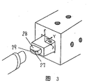
Fig. 3 is the cutter head enlarged drawing of positioning device of cutting tool of the present invention.
Fig. 4 (a) adds Ministry of worker's front view for what cutting element localization method in the past was shown.
Fig. 4 (b) is for adding the vertical view of the Ministry of worker among Fig. 4 (a).
Below, with reference to accompanying drawing to 1 examples of implementation of the present invention with explanation.
Fig. 1 adds the front view that adds the Ministry of worker and the vertical view in man-hour for turning.In Fig. 1,11 is cutting element, and 12 is workpiece, and 13 is workpiece rotating shaft anchor clamps, have from two ends holding workpiece 12 and make the function of its rotation, 14 is tool rack, and 15 is hold-down screw, and 16 is feed station, 17 is tool rack bearing surface x, 18 is tool rack bearing surface y, and tool rack 14 is fixed on the feed station 16 with hold-down screw 15 under the state of being close to bearing surface 17 and bearing surface 18, and it is moved to feeding direction 19.By making workpiece 12 rotation, and make cutting element 11 limits act on the workpiece limit to move to feeding direction 19, come the surface of processing work 12 in this way.Because the cutter head posture of cutting element 11 is to be that benchmark performs adjustment with bearing surface 17 and bearing surface 18 in advance, so can carry out mirror finish immediately after the tool rack transposing.
Secondly, utilize Fig. 2 and Fig. 3 that cutting element cutter head method of adjustment is illustrated.
Fig. 2 is a positioning device of cutting tool front view of the present invention.In addition, Fig. 3 is this cutter head portion enlarged drawing.In Fig. 2,21 is cutting element, 22 for adjusting and the fixing cutting element frame of the three-dimensional posture of cutting element 21,23 is to the thing interference microscope, 24 for being fixed on fixed station on the same position well to thing interference microscope 23 reproducibilities relatively with cutting element frame 22,25 is monitor, and 26 is interference fringe.In addition, in Fig. 3,27 is that cutter head flank, 28 is the 2nd flank of cutter head for cutter head front, 29.
For the position and the angle of the cutter head flank 27 that can carry out mirror-finish cutting, be determined once by the shape and the bar number of the interference fringe 26 that thing interference microscope 23 is retouched out on monitor 25.Therefore, opposite if will make the posture of cutting element 21 meet position and the angle that can carry out mirror-finish cutting, will make the shape of interference fringe 26 of cutter head flank 27 and bar number and the former be in the operation of equal state.Because cutting element frame 22 can be repeated repeatability and is fixed on well on the fixed station 24, so the position of cutter head flank 27 and angle can reach high accuracy (10 μ m following, 5 seconds in).
The positioning device of cutting tool and the in the past feature contrast of the localization method of cutting element of table 1 for adopting present embodiment.
Table 1
| During mirror finish | Present embodiment | Traditional scheme | |
| Modus operandi | Adopt the objectivity method of adjustment of interference microscope | Rely on skilled worker's the intuition and the handwork of experience | |
| Smart | The cutter head position | ±10μm | ±10μm |
| Degree | Cutter head angle | ± 5 seconds | ± 10 seconds |
| Adjustment number of times on the process equipment | 1 time | 5-20 time | |
| Operation rate | 95% | 85% | |
As can be seen from Table 1, adopt the positioning device of cutting tool and the cutting element method of adjustment of the present invention of present embodiment, can obtain good effect aspect adjustment number of times on the minimizing machining tool and the raising operation rate.
In sum, the present invention has and can take out and can regulate and the fixing cutting element frame of the three-dimensional posture of cutting element from machining tool, to the thing interference microscope, and the cutting element frame can be fixed on fixed station on the same position well to thing interference microscope reproducibility relatively, and under off-line state, adjustment is contained in 3 dimension postures of cutting element on the tool rack to the thing interference microscope in utilization, then, after being installed on the machining tool, tool rack with the instrument stance adjustment after good can carry out machining immediately, so, the instrument stance adjustment that can not need skilled technical ability, and owing to be a kind of off line adjustment (take out from machining tool after adjustment), therefore adopt the mode of a plurality of cutting framves of preparation just need on machining tool, not adjust, make running rate might reach top.
Claims (1)
Applications Claiming Priority (3)
| Application Number | Priority Date | Filing Date | Title |
|---|---|---|---|
| JP336227/93 | 1993-12-28 | ||
| JP33622793 | 1993-12-28 | ||
| JP336227/1993 | 1993-12-28 |
Publications (2)
| Publication Number | Publication Date |
|---|---|
| CN1111555A CN1111555A (en) | 1995-11-15 |
| CN1059373C true CN1059373C (en) | 2000-12-13 |
Family
ID=18296957
Family Applications (1)
| Application Number | Title | Priority Date | Filing Date |
|---|---|---|---|
| CN94120035A Expired - Fee Related CN1059373C (en) | 1993-12-28 | 1994-12-28 | Positioning device of cutting tool |
Country Status (3)
| Country | Link |
|---|---|
| US (2) | US5619783A (en) |
| KR (1) | KR0184533B1 (en) |
| CN (1) | CN1059373C (en) |
Cited By (1)
| Publication number | Priority date | Publication date | Assignee | Title |
|---|---|---|---|---|
| CN102145392A (en) * | 2011-03-29 | 2011-08-10 | 胡林宝 | Lathe die head for processing plane of grinding disc |
Families Citing this family (8)
| Publication number | Priority date | Publication date | Assignee | Title |
|---|---|---|---|---|
| JP3792812B2 (en) * | 1996-11-11 | 2006-07-05 | オークマ株式会社 | Ball end mill sphericity measurement method |
| US6563592B2 (en) * | 2001-03-19 | 2003-05-13 | The United States Of America As Represented By The Secretary Of The Army | Interferometric alignment device |
| US7128298B1 (en) * | 2004-05-12 | 2006-10-31 | Johnson Stanley P | Component positioning device |
| CN101028692B (en) * | 2006-03-03 | 2011-07-27 | 鸿富锦精密工业(深圳)有限公司 | Measuring device and measuring method therewith |
| US9815166B2 (en) * | 2012-01-04 | 2017-11-14 | Mike Goldstein | Inspection device for mechanical instruments and uses thereof |
| CN104625117A (en) * | 2015-01-07 | 2015-05-20 | 池州共康汽车零部件有限公司 | Hydraulic telescopic turning tool setting device |
| CN104625116A (en) * | 2015-01-07 | 2015-05-20 | 池州共康汽车零部件有限公司 | Turning tool setting device |
| CN109807689B (en) * | 2019-01-31 | 2024-07-02 | 九州能源有限公司 | Cutting auxiliary device and cutting equipment with inclined installation surface |
Citations (4)
| Publication number | Priority date | Publication date | Assignee | Title |
|---|---|---|---|---|
| DE391617C (en) * | 1922-03-17 | 1924-03-08 | Endlaugenkalk Ges M B H | Process for the production of a fertilizer |
| WO1979000082A1 (en) * | 1977-08-02 | 1979-02-22 | Automated Optics | Method and apparatus adapted for automatic or semi-automatic fabrication of ultra-precision ophthalmic lenses,e.g.,contact lenses |
| DE3916171A1 (en) * | 1989-05-18 | 1990-11-22 | Siemens Ag | Microscope attachment for setting tool on lathe axis - has microscope giving view tool tip relative to circular graticule centred on lathe axis |
| EP0520396A1 (en) * | 1991-06-24 | 1992-12-30 | Günter Heilig | Automatic measuring of a working tool |
Family Cites Families (1)
| Publication number | Priority date | Publication date | Assignee | Title |
|---|---|---|---|---|
| US4460275A (en) * | 1977-08-02 | 1984-07-17 | Automated Optics, Inc. | Method and apparatus adapted for automatic or semi-automatic fabrication of ultra-precision opthalmic lenses, e.g., contact lenses |
-
1994
- 1994-12-23 KR KR1019940036301A patent/KR0184533B1/en not_active Expired - Fee Related
- 1994-12-27 US US08/364,117 patent/US5619783A/en not_active Expired - Fee Related
- 1994-12-28 CN CN94120035A patent/CN1059373C/en not_active Expired - Fee Related
-
1997
- 1997-02-14 US US08/801,581 patent/US5784773A/en not_active Expired - Fee Related
Patent Citations (4)
| Publication number | Priority date | Publication date | Assignee | Title |
|---|---|---|---|---|
| DE391617C (en) * | 1922-03-17 | 1924-03-08 | Endlaugenkalk Ges M B H | Process for the production of a fertilizer |
| WO1979000082A1 (en) * | 1977-08-02 | 1979-02-22 | Automated Optics | Method and apparatus adapted for automatic or semi-automatic fabrication of ultra-precision ophthalmic lenses,e.g.,contact lenses |
| DE3916171A1 (en) * | 1989-05-18 | 1990-11-22 | Siemens Ag | Microscope attachment for setting tool on lathe axis - has microscope giving view tool tip relative to circular graticule centred on lathe axis |
| EP0520396A1 (en) * | 1991-06-24 | 1992-12-30 | Günter Heilig | Automatic measuring of a working tool |
Cited By (1)
| Publication number | Priority date | Publication date | Assignee | Title |
|---|---|---|---|---|
| CN102145392A (en) * | 2011-03-29 | 2011-08-10 | 胡林宝 | Lathe die head for processing plane of grinding disc |
Also Published As
| Publication number | Publication date |
|---|---|
| KR950017028A (en) | 1995-07-20 |
| US5619783A (en) | 1997-04-15 |
| KR0184533B1 (en) | 1999-05-01 |
| US5784773A (en) | 1998-07-28 |
| CN1111555A (en) | 1995-11-15 |
Similar Documents
| Publication | Publication Date | Title |
|---|---|---|
| CN1050790C (en) | Machine tool | |
| CN1059373C (en) | Positioning device of cutting tool | |
| US5193314A (en) | Computer controlled grinding machine for producing objects with complex shapes | |
| DE69113502T2 (en) | Process for manufacturing turbine blades. | |
| DE102018218298B4 (en) | Machining system | |
| ATE333671T1 (en) | METHOD FOR CONTROLLING THE WORKING MOVEMENT OF A TOOL FOR MATERIAL-REMOVAL PROCESSING OF A MATERIAL BLOCK | |
| WO1982003474A1 (en) | Digital control machining method | |
| CN102099153A (en) | Method for shifting the point of machining of a work piece and machine tool | |
| KR890000944A (en) | How to compensate for misalignment of workpieces on numerically controlled machine tools | |
| CN109471408A (en) | Geometric Error Compensation Method of Three-axis Machine Tool Based on NC Code Reconstruction | |
| DE112020002392T5 (en) | WORKPIECE PROCESSING METHOD AND WORKPIECE PROCESSING DEVICE | |
| DE102020132660A1 (en) | Control device for machine tools and machine tool control methods | |
| JPS60131106A (en) | Automatic burr removing device | |
| KR20200031130A (en) | Machine tool controls and machine tools | |
| RU2355517C2 (en) | Method and facility for surfaces milling of free form | |
| US20230103408A1 (en) | Turning method for workpiece, machine tool, and non-transitory computer-readable storage medium storing machining program | |
| DE10393160B4 (en) | Screw grinder | |
| DE19804885A1 (en) | Device for superfinishing ground surfaces | |
| JP2012071381A (en) | Non-circular machining method by turning | |
| Murphy et al. | CAD directed robotic deburring | |
| JP2000515075A (en) | 3-axis lathe that performs polar coordinate motion | |
| JPH06711A (en) | Cutting method | |
| EP3801964A1 (en) | Multi-tool chamfering device for toothed workpieces | |
| DE69120060T2 (en) | CONTACTLESS DIGITIZATION PROCESS | |
| CN216178402U (en) | Lifting straight-swinging type feeding driving structure |
Legal Events
| Date | Code | Title | Description |
|---|---|---|---|
| C06 | Publication | ||
| PB01 | Publication | ||
| C10 | Entry into substantive examination | ||
| SE01 | Entry into force of request for substantive examination | ||
| C14 | Grant of patent or utility model | ||
| GR01 | Patent grant | ||
| C19 | Lapse of patent right due to non-payment of the annual fee | ||
| CF01 | Termination of patent right due to non-payment of annual fee |