CN1057856C - Improvements in photo display devices - Google Patents
Improvements in photo display devices Download PDFInfo
- Publication number
- CN1057856C CN1057856C CN92110184A CN92110184A CN1057856C CN 1057856 C CN1057856 C CN 1057856C CN 92110184 A CN92110184 A CN 92110184A CN 92110184 A CN92110184 A CN 92110184A CN 1057856 C CN1057856 C CN 1057856C
- Authority
- CN
- China
- Prior art keywords
- ratchet
- case shell
- roller assembly
- roller
- framework
- Prior art date
- Legal status (The legal status is an assumption and is not a legal conclusion. Google has not performed a legal analysis and makes no representation as to the accuracy of the status listed.)
- Expired - Fee Related
Links
Images


Classifications
-
- G—PHYSICS
- G09—EDUCATION; CRYPTOGRAPHY; DISPLAY; ADVERTISING; SEALS
- G09F—DISPLAYING; ADVERTISING; SIGNS; LABELS OR NAME-PLATES; SEALS
- G09F11/00—Indicating arrangements for variable information in which the complete information is permanently attached to a movable support which brings it to the display position
- G09F11/02—Indicating arrangements for variable information in which the complete information is permanently attached to a movable support which brings it to the display position the display elements being secured to rotating members, e.g. drums, spindles
- G09F11/06—Indicating arrangements for variable information in which the complete information is permanently attached to a movable support which brings it to the display position the display elements being secured to rotating members, e.g. drums, spindles the elements being stiff plates or cards
Landscapes
- Physics & Mathematics (AREA)
- General Physics & Mathematics (AREA)
- Engineering & Computer Science (AREA)
- Theoretical Computer Science (AREA)
- Displays For Variable Information Using Movable Means (AREA)
- Toys (AREA)
Abstract
An improved photo display device of the type having a housing with frame and double photograph envelope providing dual photo viewing as presented within the frame, a first improvement consisting of an alternative picture rotating mechanism that includes both a manual ratcheting system on one side of the housing and a motor drive or automatic ratcheting system on the other side, and a second improvement that consists of a unitary housing/frame formation that receives a spindle assembly directly through the front frame which is then secured by side entry and snap-fit of right and left ratcheting knob assemblies.
Description
The present invention relates to improved constructing technology of many photo display box and rotary drive mechanism.
The present invention relates to sequence number is No.07/591,052 U.S. Patent application formerly and sequence number thereof are No.07/628, the theme of 164 part continuation application, described U.S. Patent application are applications on October 1 nineteen ninety, and name is called: " improved photo display devices "; Described continuation application is application on Dec 17 nineteen ninety.
Existing all kinds of card retrieval device is generally people to be concerned about, for no other reason than that they the most normal be its feature with such fact, i.e. the one side that only need after retrieval, show card.Early stage U.S. Patent No. 1,813,442 discloses a kind of two visual fields that comprise, i.e. the mechanical rotation formula symbol display device showed simultaneously of the back side of the front of top card and bottom card.U.S. Patent No. 1,126,814 disclose the picture presentation device of another kind of form, and wherein, the rotation reel that respectively comprises some pictures is displayed selectively.
U.S. Patent No. 978,162 also discloses the picture presentation device of another kind of form, and wherein, plurality of pictures rotates around Z-axis in surface level.U.S. Patent No. 3,218,743 disclose a kind of picture presentation device, and this device has adopted a kind of photo album formula collection method of single photo, wherein, looks each picture for seeing respectively continuously, and each photo album all can insert in the exhibiting device.European patent application No.82104601.8 mainly is the rotation menu card plate rack that is used in the micro-wave oven about a kind of, and wherein, when this device stirred, the back side and the front of card all can be demonstrated out.
The present invention relates to the improvement of photo display devices structure, this improvement mainly is to be put the mode that is dissolved in the tank shell with the displaying of controlling many pictures roller bearing by integral body at rotation driving and/or movement control elements and these elements.Particularly, an incorporate rear cabinet shell component matches with front baffle, and the picture roller assembly is fixed on operating position.This roller assembly is suitable in each respective side edge a ratchet being installed, and have a motor and in order to by an operated driven linkage that ratchet rotates this roller bearing, simultaneously, the ratchet of mechanical ratchet wheel arm and opposite side interacts, and impels the picture conversion according to manual operation.Like this, this device has been simplified widely, and the automatic operation and the picking operation of sequence of pictures also are provided simultaneously.
The possibility that adopts monomer structure has been considered in this improvement in design, i.e. the formation of framework and case shell integral body can be by casting mold or by other making such as pottery, timber or other material.In this structure, relative each side of case shell is shaped on the hole of aligning, so that the suitable roller bearing structure of inserting between each hole can be by inserting the knob structure of opposite side in logical each hole and operationally fixing, so that interlock in each end of roller assembly.Ratchet/bearing arrangement can insert from the outside and unite with corresponding knob and work, thereby required directed engagement capability is provided.
Therefore, that an object of the present invention is to provide a kind of simplification and the picture presentation device of reliable structure more.
Another object of the present invention provides a kind of multicomponent picture presentation device, and this device is open-and-shut in assembling and operating aspect.
A further object of the present invention provide a kind of have operate the more picture presentation device of reliable mechanism, its also demonstrates simultaneously the non-fault service life of prolongation.
At last, an object of the present invention is to provide and a kind ofly have firm physical arrangement simultaneously also at the reliable exhibiting device of operating aspect.
Other purpose of the present invention and advantage will be from simultaneously being known understanding in conjunction with describing the following detailed description that accompanying drawing of the present invention carries out.
Fig. 1 is the front elevation view of this exhibiting device;
Fig. 2 is the decomposition side view of this exhibiting device;
Fig. 3 is the vertical cross section along the 3-3 line intercepting of Fig. 1;
Fig. 4 is the side cutaway view along the 4-4 line intercepting of Fig. 1;
Fig. 5 is the plan view from above of passing the horizontal cross-section of roller assembly intercepting;
Fig. 6 is the exploded view of the roller tube of band ratchet and axle sleeve structure;
Fig. 7 A is the planimetric map of the photo big envelope of the body plan according to the present invention;
Fig. 7 B is a planimetric map of describing the mode on the roller bearing that big envelope is installed on;
Fig. 7 C is the side view that includes the roller assembly that all photo big envelopes have been installed;
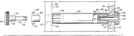
Fig. 8 is installed on the roller assembly in the tank shell and the exploded view of knob structure, and wherein the right side knob structure shows with section;
Fig. 9 A is the side view of the ratchet wheel key of formation according to the present invention;
Fig. 9 B is the plan view from above of the ratchet wheel key of Fig. 9 A;
Figure 10 is the cut-open view of roller bearing plug connector shown in Figure 8;
Figure 11 is the longitudinal sectional view of knob shown in Figure 8.
See figures.1.and.2, photo display devices 10 comprises a front baffle 12, and this front baffle 12 is changed a social system among being buckled in case shell 14.Inner edge along framework 12 is shaped on a broach 24.Rectangle front baffle 12 comprises opposed side edges 16 and 18, top margin 20 and base 22, and is provided with digraph sheet visual field.Be that front-view area 26 is divided into and is used to see last vision area 28 of looking first pictures and the following vision area 30 that is used to show second pictures.Vision area 28 and 30 all is suitable for showing the standard-sized photo of looking that is used to see, and for example, the snapshot photograph of 3 * 5 inch (9 * 12.7 centimetres) will be as below will further discussing.A upper comb dent extension 24a provides one to go up escapement, and continuous picture big envelope discharges thus.
Case columella neck extends tongue piece 42 and forms and stretch out from each of sidewall 36 is inboard, and each tongue piece 42 comprises the axis hole 43 that is used to install picture rolling sleeve axle.Front baffle 12 forms an inwall extension 44 on each side, this part 44 has axial trough 46 longitudinally, is used for photo/roller assembly is clamped in each side, and keeps suitable right alignment during operation.At last, Fig. 2 also illustrates, and on the former frame frame 12, ratchet pawl 48 Unitarily molded forming are as will be further described below.
Referring now to Fig. 3, show the present invention here automatically or the tool outfit of motor driven.Device is as shown in the figure worked with the roller bearing and the big envelope of installation in position.Like this, roller bearing axle 50 snaps in the arm of ratchet 52, and single big envelope 49 illustrates by ring shooting.An electro-motor 54 is installed in the lower relief angle of case shell 14, and motor 54 provides very slow rotation to export to a crankwheel 56, and this takes turns 56 crank pins 58 that have in the groove 60 of an embedding crank arm 52.Motor 54 can be the commercial available electro-motor of any kind of, and it comprises essential gear structure, so that low rpm (rotations per minute) output is provided.Therefore, clearly along with the inhour of crankwheel 56 is rotated, when the pawl parts 61 driving pawls 62 tooth mouth that advances, arm of ratchet 52 is just upwards driven, and the next one big envelope that will discharge is pushed over the escapement piece that is positioned on the broach of top like this, and bottom being fallen.
Fig. 4 illustrates the offside of photo display devices 10, i.e. manual operational unit.This side of roller bearing has the ratchet 64 that is fixed between big envelope 49 sequences and the outer shaft 66.An arm of ratchet operating mechanism comprises an integrally formed pressing slide block 68, and this slide block 68 extends to arm of ratchet 70, arm of ratchet 70 and returning spring 72 whole formation.Therefore, arm of ratchet 70 and returning spring 72 are all inserted the operation slotted eye 74 of logical case shell 32 back side roof parts.The installation that is fixed of a ratchet pawl 76, in fact it is with the tooth engagement of manual ratchet 64, so that with arm of ratchet 70 motions.The inner of arm of ratchet 70 comprises a hole 81 that is used to install the axle 66 of roller assembly.Therefore, clearly, travelling forward of arm of ratchet slide piece 68 will cause the engagement of pawl 76 and ratchet 64, and give its expulsive force forward that is enough to cover assembly is rotated, and directly only discharge a single big envelope 49.
With reference to Fig. 5, a common horizontal cross-section that passes exhibiting device 10 is depicted the position of roller assembly fully.Refer again to Fig. 6, the roller bearing 80 of tubular is plugged with corresponding rolling sleeve 82,84 at each end.Each rolling sleeve 82,84 as shown in Figure 6 is configured to comprise an axle neck 86 and the axle 50,66 with lock pin 90.At the left-hand side of roller assembly, because in the locked groove 92 that lock pin 90 embeds on the ratchet, ratchet 51 is fixed on the axle 50.Relative ratchet 64 is locked on the axle 86 of this exhibiting device opposite side in a similar manner.The outermost end of axle 50,66 buckle is thereafter advanced relative case columella neck and is extended (see figure 2) in the hole 43 in the tongue piece 42.
A plurality of big envelopes 49 with related application in identical mode be arranged and be fixed on the roller bearing 80.Promptly, each big envelope 49 with selected dimension of picture forms a single page, this page is converted into a long end and the short end with left and right sides of opening, and short end is sealed to long end by the hot weld seam 100 that extends along an edge, and reserves an end portion 102.Though any in many kinds of plastic sheetings all can be used to constitute roller bearing and cover assembly, adopts polypropylene to obtain extraordinary result.With reference to Fig. 7 B, discrete big envelope 49 is fixed on the roller bearing 80 by the end portion 102 around a plurality of big envelopes 49 of roller bearing 80 order hot welds.In Fig. 7 B, hot weld seam 104 plays the effect of fixing single big envelope 49, and a plurality of such hot weld seam will be around distribution, so that fixing desirable same a plurality of big envelopes.By adopting the polymer manufacture big envelope and the roller bearing of identical type, will obtain easy, firm welding, thereby a large amount of big envelopes can be fixed by intimate position around each roller bearing, and the free activity of mode that each big envelope 49 can similar hinged installation.Adopt the roller bearing 80 of about 25 millimeters (1 inch) diameters, can fix on it with very not crowded arrangement mode, two photos are arranged on each big envelope 49, therefore can hold 100 photos reaching 50 big envelopes.
Refer again to Fig. 6, show one here and novel crank arm 70.Also with reference to Fig. 4.Cranking arm 70 is formed with bandy shoulder 110, and this shoulder 110 extends termination 112 downwards, is used to provide the axle journal to roller bearing axle 66 to support.Therefore, shoulder 110 has formed the outer side clearance around ratchet 64.Simultaneously, an oblique reclinate flange is for forming pawl 76.In Fig. 3, arm of ratchet 52 is formed with a shoulder bending in the same manner, the gap of ratchet 62 not only is provided, and the support of roller bearing axle 50 is provided, and flange bending part 61 is as ratchet pawl (see figure 3).
In operation, roller bearing 80 can so load, and promptly each big envelope comprises its two photos that are inverted, and corresponding rolling sleeve 82 and 84 (Fig. 6) is placed in the roller bearing 80, and each is equipped with corresponding ratchet 62 and 64.With reference to Fig. 2, roller bearing/picture cover assembly is pressed onto the axle journal that stretches out from the sidewall 36 of case shell 14 thereafter and extends on the tongue piece 42.After this, front baffle 12 is pressed onto the front portion of case shell 14, in this process, and opposing sidewalls extension 44 sliding nearly adjacent rolling sleeve 82 and 84 (see figure 5)s, and the roller bearing groove 46 of opposite side is along opposite side axle journal 86 slip (see figure 6)s.After this front baffle 12 is pressed against the position of the front portion that covers case shell 14, and clamped by hook part 40.
Referring now to Fig. 3 and Fig. 4, when front baffle 12 is installed into case shell 14 that roller bearing/cover assembly has been placed in one anterior, 52 (Fig. 3) that crank arm will be placed on the roller bearing axle 50 of the pawl 61 that has mesh ratchet gear 62.Similarly, also will be in suitable confined state at the hand control part of exhibiting device opposite side, manually arm of ratchet 70 is placed on the roller bearing axle 66 of the pawl 76 that has mesh ratchet gear 64.Exhibiting device is operational fully thereafter, and can be used for the automatic or manual operation at any time.
For automatic operation, motor operated switch and power supply (not shown) are activated and are used for encouraging motor 54, this motor is with the very low rotating speed rotation of per minute, and therefore swing arm of ratchet 52 by the motion of one group of ratchet, each swing all will discharge next big envelope 49 from last escapement parts 24a, and it is seen at one and drops to escapement parts 38a during fixation pause pauses like this.In each case, a pictures both can also can be looked in visual space, the end in top view space 28 in 30 quilt sights.
Manual operation is carried out in a similar manner, when the compression of pressing slide block 68 and arm of ratchet 70 contrary springs 72 travels forward.The motion of ratchet 64 is enough to discharge a big envelope 49 from the vertical parts 24a of last Qin, and it just drops to down escapement parts 38a like this, and demonstrates out the upper and lower picture of next sequence.The elastic force of returning spring arm 72 makes slide switch 68 move to its original position, and the rotation of the motion of picture or big envelope 49 no longer carries out, until the manually reach next time of pressing slide block 68.
In Fig. 8, another kind of roller assembly uses with incorporate case shell/frame assembly 120.For simplicity, only show the relative side part of case shell/framework 120; But, the global shape of case shell/framework 120 appropriate section desirable and other two-piece type the basic configuration identical with the inner space, promptly roller bearing will be similar arc outer cover with the revolution space that big envelope rotates within it.The relative side of case shell/framework 120 is provided with the hole 122,124 near the identical size of case shell/framework 120 front portions, and corresponding ratchet parts of bearings 126,128 pins are embedded in the hole 122,124, as will be further described below.
As described above, the length of roller bearing 130 that carries the big envelope that the digraph sheet is housed in a week make it just in time only can pack into relative inwall or big envelope led between the wall 132,134, and every end of roller bearing 130 is installed a corresponding roller bearing plug connector 136 and 138 with tight interlocking fixed form.Roller bearing plug connector 136 is shown in broken lines, and further specifies with reference to Figure 10.At last, when the knob 140,142 of opposite side be inserted into and fastener behind interlocking position, whole assembling has just been finished, this also will further describe in the back.
Referring now to Fig. 9 A and 9B, ratchet/parts of bearings 126 and 128 is except they form with the mirror image counter structure, they have identical construction, each has a cylindrical shell 144, the size of cylindrical shell 144 is suitable for packing in corresponding hole 122 and 124, and cylindrical shell 144 provides a sleeve surface 146 of passing wherein.A guiding key pin 148 is formed on the cylindrical shell 144, so as interlocking hole 122 and 124 and the sidewall of case shell/framework 120 among insertion within the keyway (not illustrating especially) that forms.An outside formation of radially extending broach 150 along cylindrical shell 144, and around extending to form a concentric ratchet pawl 152, so that match with non-return knob, just as will be described further.
Figure 10 shows the cut-open view of roller bearing plug connector 136 and 138.Roller bearing plug connector 136 and 138 all is formed with an outer rim 154, and outer rim 154 has a cylinder 156, and forms a plurality of anti-skidding rib 158 (see figure 8)s along the circumference of cylinder 156, so that obtain closely in roller tube 130 and quite lasting engagement.Because the support of sufficiently long web (webbing) 162 (illustrating especially), an inner square duct 160 forms in cylinder 156 with one heart, so that interact with a projected square part that matches of control handle, as will be further described below.
Referring now to Figure 11, knob 140 and 142 respectively comprises an outer knob 166 that forms on a tubular turning axle 168, turning axle 168 comprises that one is used for being used in rolling sleeve 136 and 138 and the projected square part 172 of square internal channel 160 locking engagements the outer ring portion 170 of the smooth engagement of lining 146 (seeing Fig. 9 B) and one.A plurality of ratchets 174 form along the inner edge of knob 166, are used for matching with ratchet pawl 152 (Fig. 9 B) after assembling is finished.The flexible dop 176 of perpendicular array is formed on the inner of cylindrical part 168, is used for when single unit system knob assembly 140,142 lockings being put in place.
The structure that assembles illustrates in the sectional view of Fig. 8 better.
Mainly with reference to Fig. 8, in this total implementation device, the roller bearing 130 that has a plurality of digraph sheet big envelopes is manually inserted in the open front framework of case shell/framework 120, and relative roller bearing plug connector 136 and 138 is aimed at corresponding hole 122 and 124.Ratchet plug connector 126 and 128 have been inserted into supported hole 122 and 124 from the outside.After this, corresponding knob 140 and 142 is inserted into by ratchet/parts of bearings 126 and 128 corresponding linings 146, in annular section 170 is placed in lining 146 (each side), square tube shape part 172 is inserted into by the interior square duct 160 of each roller bearing plug connector 136 and 138, so that their corresponding locking dops outwards launch with interlock method.When assembling like this, ratchet 174 in the knob 166 cap shells will mesh with ratchet pawl 152, so that the restriction roller bearing only rotates in a direction, the release of the digraph sheet big envelope that control is in the opposite direction simultaneously upwards arranged continuously, so that look the photo of tossing about for seeing, each big envelope falls to down the escapement component locations.
Aforementionedly disclose a kind of new of picture presentation device, wherein manual and automatic operation all can be used, and two kinds of modes of operation realize by a kind of more basic mechanism.No matter still be manual operation automatically, this device all can be worked very reliably, and it can easily be applicable to the assembly of using that has a plurality of roller bearings/big envelope picture in can being called the operation of photo album formula.
Element arrangements that describe in the instructions as the front and that show in the accompanying drawings and combination can change, should be understood that, under the prerequisite that does not break away from the spirit and scope of the present invention that are limited by the accompanying claims, in disclosed embodiment, can make various variations.
Claims (16)
1. photo storage and exhibiting device comprise: a case shell, and it has the open front of essentially rectangular, and described front portion has top margin, base and opposed side edges;
A framework, it limits upper and lower photo vision area, and described framework is placed in the open front of described case shell in knock-down mode;
A roller assembly, it comprises a plurality of big envelopes that flexibly continued circling is fixing, and each big envelope includes and can see the photo of looking from each side, and described roller assembly rotatably places on the bisector of open front of described case shell;
A ratchet, it is fixed on an end of described roller assembly and can rotates therewith;
An arm of ratchet, it has first and second ends, and described first end is rotatably fixed to an end of described roller assembly, and extends a ratchet pawl that is engaged on the described ratchet; With
Motor and crankwheel, it slides with second end of arm of ratchet and is connected, and makes it to produce the to-and-fro movement of inclination, and the motion of ratchet pawl causes the periodic rotary of ratchet, thereby makes each continuous big envelope move to down vision area from last vision area.
2. the device described in claim 1, wherein said roller assembly further comprises:
A roller tube, it sequentially fixes described a plurality of big envelope around it; With
First and second insert the axle sleeve of the opposite end of described roller tube, and each axle sleeve extends a roller bearing axle, so that setting-in is gone in the opposite side of open front of described case shell.
3. the device described in claim 2, wherein: described ratchet is installed on one of described roller bearing axle, and near the roller tube setting.
4. the device described in claim 1, wherein said framework further comprises:
Connect into top margin, base and the opposed side edges parts of a rectangular frame;
The first and second framework inner panels, they are installed on the corresponding side members separately, and each fixing inner panel respective edges of becoming an accurate straight line to stretch to described a plurality of big envelopes in set case shell, so that photo clip is held in wherein.
5. the device described in claim 3, it is further characterized in that and comprises:
A pawl, it is in a side position and the whole formation of described framework of contiguous roller assembly, to prevent described ratchet reversing.
6. photo storage and exhibiting device comprise: a case shell, and it has the open front of essentially rectangular, and described front portion has top margin, base and opposed side edges;
A framework, it limits upper and lower photo vision area, and described framework is placed in the open front of described case shell in knock-down mode;
A roller assembly, it comprises a plurality of big envelopes that flexibly continued circling is fixing, and each big envelope includes and can see the photo of looking by each side, and described roller assembly rotatably places on the bisector of open front of described case shell;
A ratchet, it is fixed on an end of described roller assembly, and can rotate therewith;
An arm of ratchet, it has first and second ends, described first end is rotatably fixed to an end of described roller assembly, and stretch out a ratchet pawl with described ratchet engaged, the opening that second end passes on the described case shell is protruding, thereby so that provides manual operation to described ratchet and roller assembly at described this second end of case shell slide outside.
7. the device described in claim 6, wherein said roller assembly further comprises:
A roller tube, it makes described a plurality of big envelope order fix around it; With
First and second insert the axle sleeve of the opposite end of described roller tube, and each axle sleeve extends a roller bearing axle, so that setting-in is gone into the relative anterior side of described case shell.
8. the device described in claim 7, wherein:
Described ratchet is installed on one of described roller bearing axle, and contiguous roller tube setting.
9. the device described in claim 6, wherein said framework further comprises:
Connect into top margin, base and the opposed side edges parts of a rectangular frame;
The first and second framework inner panels, they are contained on the corresponding side separately, and each fixing inner panel respective edges of becoming an accurate straight line to stretch to described a plurality of big envelopes in said case shell, so that photo clip is held in wherein.
10. the device described in claim 8, it is further characterized in that and comprises:
A pawl, it is in a side position and the whole formation of described framework of contiguous roller assembly, to prevent described ratchet reversing.
11. the device described in claim 6, it is further characterized in that and comprises:
One second ratchet, it is fixed on the opposite end of described roller assembly, and can rotate therewith;
An arm of ratchet, it has first and second ends, described first end rotatably is fixed on the opposite end of described roller assembly, and extend second a ratchet pawl with described second ratchet engaged, it is protruding that second end passes an opening of described case shell, so that outside described case shell, slide this second end, thereby provide manual operation to described ratchet and roller assembly.
12. photo storage and exhibiting device comprise:
A case shell outer cover, it has pedestal, relative sidewall, curved back and roof, they are integrally formed with front baffle, described framework defines an open front with rectangle of upper and lower vision area, and described case shell has and passing first and second holes that relative sidewall forms in line;
A roller assembly, it has around the fixing a plurality of big envelopes of its perisporium, and each big envelope includes the photo of back-to-back placement, and described roller assembly is installed between the described case shell side wall, and locatees in line between described first and second holes;
First and second knob assemblies, they each have a knob and a coaxial tubular turning axle so that insert corresponding first and second holes, and with the attaching of roller assembly buckle-type.
13. the device described in claim 12, wherein roller assembly is further characterized in that and comprises:
One tubular roller bearing; With
The first and second roller bearing plug connectors, they are installed in the opposite end of roller bearing, and each has a coaxial configuration described roller bearing plug connector, is used for installing with interlock method therein the tubular turning axle of corresponding knob assembly.
14. the device described in claim 13, it is further characterized in that and comprises:
The first and second key lock shaft socket joint fittings, they are placed in the described relative sidewall coaxial aperture, and a coaxial bearings surface is provided, and being used to install first and second knob assemblies and tubular turning axle, each extends a concentric ratchet pawl described bearing unit.
15. the device described in claim 14, it is further characterized in that and comprises:
A plurality of ratchets, they form along the inner edge of each described knob, are used for cooperating with the concentric ratchet pawl of the described first and second key lock shaft socket joint fittings.
16. the device described in claim 14, wherein:
Each described tubular turning axle comprises the annular section of a corresponding knob of vicinity, be used for contacting with the described bearing surface rotation of corresponding bearing plug connector, a square barrel is stretched out from this annular section, is used for interlocking inserting the square coaxial configuration of a corresponding roller bearing plug connector.
Applications Claiming Priority (2)
| Application Number | Priority Date | Filing Date | Title |
|---|---|---|---|
| US07/908,300 US5289651A (en) | 1990-12-17 | 1992-07-02 | Photo display devices |
| US908,300 | 1992-07-02 |
Publications (2)
| Publication Number | Publication Date |
|---|---|
| CN1080758A CN1080758A (en) | 1994-01-12 |
| CN1057856C true CN1057856C (en) | 2000-10-25 |
Family
ID=25425550
Family Applications (1)
| Application Number | Title | Priority Date | Filing Date |
|---|---|---|---|
| CN92110184A Expired - Fee Related CN1057856C (en) | 1992-07-02 | 1992-09-01 | Improvements in photo display devices |
Country Status (5)
| Country | Link |
|---|---|
| US (1) | US5289651A (en) |
| EP (1) | EP0581430B1 (en) |
| JP (1) | JPH0659213A (en) |
| CN (1) | CN1057856C (en) |
| DE (1) | DE69308952D1 (en) |
Families Citing this family (10)
| Publication number | Priority date | Publication date | Assignee | Title |
|---|---|---|---|---|
| DE4428528A1 (en) * | 1994-08-12 | 1996-02-22 | Krone Ag | Fall sheet display module |
| US6119381A (en) * | 1996-12-31 | 2000-09-19 | Grocholski; Adam | Disc storage and display device |
| FR2843691B1 (en) * | 2002-08-26 | 2005-04-01 | Roland Robert | DEVICE FOR PRESENTING PHOTOGRAPHS OR OBJECTS ESSENTIALLY SIMILAR DECORATIVE DISHES |
| JP4058374B2 (en) * | 2003-03-07 | 2008-03-05 | キヤノンファインテック株式会社 | Sheet processing apparatus and image forming apparatus provided with the apparatus |
| US7583923B2 (en) * | 2004-05-06 | 2009-09-01 | Samsung Electronics Co., Ltd. | Bearing structure and fusing device for image forming apparatus employing the bearing structure |
| US20090119965A1 (en) * | 2007-11-09 | 2009-05-14 | Wilton Industries, Inc. | Picture frame |
| US7637043B2 (en) * | 2008-03-11 | 2009-12-29 | Brown Jr Jimmie R | Motorized photo display |
| US10034558B2 (en) * | 2016-08-30 | 2018-07-31 | Pepsico, Inc. | Product display systems and methods |
| US10506888B2 (en) | 2017-12-06 | 2019-12-17 | Bay Island, LLC | Frame with interchangeable panels |
| US11482139B2 (en) * | 2019-07-01 | 2022-10-25 | Vestaboard, Inc. | Latch for mount and dismount of a modular housing |
Family Cites Families (34)
| Publication number | Priority date | Publication date | Assignee | Title |
|---|---|---|---|---|
| US512034A (en) * | 1894-01-02 | Charles m | ||
| US421266A (en) * | 1890-02-11 | Album or picture-exhibitor | ||
| US380090A (en) * | 1888-03-27 | John b | ||
| US686965A (en) * | 1901-04-09 | 1901-11-19 | Leopold Breton | Picture-exhibitor. |
| US978162A (en) * | 1909-03-09 | 1910-12-13 | Leslie Hopkins | Sign-exhibiting apparatus. |
| US1006188A (en) * | 1910-10-18 | 1911-10-17 | Curtis G Edson | Street-indicator. |
| US1126814A (en) * | 1913-04-25 | 1915-02-02 | Louis L Manetsch | Picture-exhibitor. |
| US1214732A (en) * | 1915-08-13 | 1917-02-06 | Robert Hopkins | Card-display device. |
| US1713140A (en) * | 1924-09-10 | 1929-05-14 | Mcdonald Securities Company Lt | Advertising apparatus |
| US1596741A (en) * | 1925-10-16 | 1926-08-17 | Kranz Richard | Filing device for cards and the like |
| US1848296A (en) * | 1928-05-11 | 1932-03-08 | Trico Products Corp | Advertising device |
| DE574990C (en) * | 1928-12-02 | 1933-04-21 | Siemens & Halske Akt Ges | Device for controlling the movement of display boards in display devices |
| US1813442A (en) * | 1930-03-05 | 1931-07-07 | Motor Car Advertising Device C | Advertising device |
| CH176167A (en) * | 1934-03-13 | 1935-03-31 | Moeller Friedrich | Advertising machine with swiveling, exchangeable signs. |
| US2554941A (en) * | 1946-04-05 | 1951-05-29 | Dobrowsky Emmanuel | Musical toy |
| GB619299A (en) * | 1946-12-02 | 1949-03-07 | Trevor Hammond | Improvements in or relating to apparatus for displaying information for advertising or other purposes, for example, announcing |
| US2703744A (en) * | 1951-04-28 | 1955-03-08 | Abraham S Karper | Rotary card file |
| US2761750A (en) * | 1951-07-03 | 1956-09-04 | Zephyr American Corp | Rotary card filing device and card backing means therein |
| US3212205A (en) * | 1962-02-05 | 1965-10-19 | Ronald D Alleman | Animation device |
| US3218743A (en) * | 1962-07-16 | 1965-11-23 | Shneider Aaron Harry | Device for storing and displaying photographs, snapshots and the like |
| US3260006A (en) * | 1963-12-13 | 1966-07-12 | Dunmar Products Inc | Card clip |
| US3261649A (en) * | 1964-07-17 | 1966-07-19 | Dial A Card Inc | Card holder and dialer |
| US3323243A (en) * | 1965-09-27 | 1967-06-06 | Edgar W Blair | Rotary display unit |
| US3973339A (en) * | 1972-12-25 | 1976-08-10 | Copal Company Limited | Flap type indicating device |
| JPS50128266A (en) * | 1974-03-26 | 1975-10-09 | ||
| FR2266247B1 (en) * | 1974-03-28 | 1979-04-20 | Derot Marie Therese | |
| US4021947A (en) * | 1975-10-30 | 1977-05-10 | Shneider Aaron H | Rotary display stands |
| US4215511A (en) * | 1978-08-11 | 1980-08-05 | Masatoshi Todokoro | Toy television set with musical box |
| US4517428A (en) * | 1981-05-29 | 1985-05-14 | Tokyo Shibaura Denki Kabushiki Kaisha | Menu display device |
| US4530176A (en) * | 1983-09-27 | 1985-07-23 | Berkey Photo, Inc. | Apparatus for cataloguing photographs and negatives |
| US4514919A (en) * | 1983-10-17 | 1985-05-07 | Pioneer Photo Albums, Inc. | Apparatus for storing, displaying and identifying photographs |
| US4599815A (en) * | 1984-08-31 | 1986-07-15 | Waldo Tim R | Photograph display wheel |
| US4832369A (en) * | 1987-10-30 | 1989-05-23 | Johnson Gary W | Wind resistant clipboard/padholder |
| US5493803A (en) * | 1990-10-01 | 1996-02-27 | Byers; Thomas L. | Photo display device |
-
1992
- 1992-07-02 US US07/908,300 patent/US5289651A/en not_active Expired - Fee Related
- 1992-09-01 CN CN92110184A patent/CN1057856C/en not_active Expired - Fee Related
- 1992-11-04 JP JP4317955A patent/JPH0659213A/en not_active Withdrawn
-
1993
- 1993-06-14 DE DE69308952T patent/DE69308952D1/en not_active Expired - Lifetime
- 1993-06-14 EP EP93304583A patent/EP0581430B1/en not_active Expired - Lifetime
Also Published As
| Publication number | Publication date |
|---|---|
| US5289651A (en) | 1994-03-01 |
| EP0581430B1 (en) | 1997-03-19 |
| JPH0659213A (en) | 1994-03-04 |
| EP0581430A3 (en) | 1994-03-23 |
| EP0581430A2 (en) | 1994-02-02 |
| DE69308952D1 (en) | 1997-04-24 |
| CN1080758A (en) | 1994-01-12 |
Similar Documents
| Publication | Publication Date | Title |
|---|---|---|
| CN1057856C (en) | Improvements in photo display devices | |
| US4809137A (en) | Back-mirror fitted with illumination light at car side | |
| CN1152283C (en) | Fil unit with waterproof lens and waterproof ring | |
| EP1381004B1 (en) | Rotation type camera apparatus | |
| CN1488050A (en) | Actuator for driving rotary valve and valve device with the actuator | |
| EP1229406A3 (en) | Coupling part for photosensitive drum in process cartridge and electrophotographic image forming apparatus | |
| EP1068982A3 (en) | Display apparatus and display drive mechanism for vehicle | |
| CN1025375C (en) | Film cassette with lock-out means for preventing load of exposed film | |
| CN1164681A (en) | Toner supply device and toner cartridge | |
| US4995568A (en) | Wire terminal attaching structure of a driven rotary body | |
| US5145467A (en) | Geared motor for the drive of components, such as motor-vehicle accessories, particularly an opening roof | |
| US6064846A (en) | Developer container including flange for supporting container on flat surface | |
| CN1058657A (en) | The magazine that the film exposure positioning indicator is arranged | |
| US6266090B1 (en) | Device for controlling a rotation of a lens in a digital camera | |
| CN219122560U (en) | Projector focusing structure and projector | |
| CN1191996A (en) | Toner replenishing device of image forming machine and toner cartridge for use therein | |
| US5737861A (en) | Intermittent motion gear box | |
| CN211043915U (en) | Imaging device based on film | |
| US6597864B2 (en) | Process and an apparatus for loading a disposable camera with a photographic roll film, and a disposable camera loaded with a photographic roll film | |
| CN1080894C (en) | Film winding apparatus | |
| CN1026164C (en) | Film Cassette with film exposure status indicator | |
| CN1577158A (en) | Developer supply device and container for holding developer | |
| US4690535A (en) | Automatic film processor arrangement | |
| CN1296108A (en) | Press-button lock | |
| CN1165322A (en) | Film cartridge |
Legal Events
| Date | Code | Title | Description |
|---|---|---|---|
| C06 | Publication | ||
| PB01 | Publication | ||
| C10 | Entry into substantive examination | ||
| SE01 | Entry into force of request for substantive examination | ||
| C14 | Grant of patent or utility model | ||
| GR01 | Patent grant | ||
| C15 | Extension of patent right duration from 15 to 20 years for appl. with date before 31.12.1992 and still valid on 11.12.2001 (patent law change 1993) | ||
| OR01 | Other related matters | ||
| C19 | Lapse of patent right due to non-payment of the annual fee | ||
| CF01 | Termination of patent right due to non-payment of annual fee |