CN105701793B - Method and apparatus for digitizing the appearance of real materials - Google Patents
Method and apparatus for digitizing the appearance of real materials Download PDFInfo
- Publication number
- CN105701793B CN105701793B CN201510917597.0A CN201510917597A CN105701793B CN 105701793 B CN105701793 B CN 105701793B CN 201510917597 A CN201510917597 A CN 201510917597A CN 105701793 B CN105701793 B CN 105701793B
- Authority
- CN
- China
- Prior art keywords
- data
- image
- image data
- light source
- light
- Prior art date
- Legal status (The legal status is an assumption and is not a legal conclusion. Google has not performed a legal analysis and makes no representation as to the accuracy of the status listed.)
- Active
Links
Images


Classifications
-
- G—PHYSICS
- G06—COMPUTING; CALCULATING OR COUNTING
- G06T—IMAGE DATA PROCESSING OR GENERATION, IN GENERAL
- G06T7/00—Image analysis
- G06T7/0002—Inspection of images, e.g. flaw detection
- G06T7/0004—Industrial image inspection
-
- G—PHYSICS
- G06—COMPUTING; CALCULATING OR COUNTING
- G06T—IMAGE DATA PROCESSING OR GENERATION, IN GENERAL
- G06T15/00—3D [Three Dimensional] image rendering
- G06T15/10—Geometric effects
-
- G—PHYSICS
- G01—MEASURING; TESTING
- G01N—INVESTIGATING OR ANALYSING MATERIALS BY DETERMINING THEIR CHEMICAL OR PHYSICAL PROPERTIES
- G01N21/00—Investigating or analysing materials by the use of optical means, i.e. using sub-millimetre waves, infrared, visible or ultraviolet light
- G01N21/17—Systems in which incident light is modified in accordance with the properties of the material investigated
- G01N21/55—Specular reflectivity
- G01N21/57—Measuring gloss
-
- G—PHYSICS
- G01—MEASURING; TESTING
- G01B—MEASURING LENGTH, THICKNESS OR SIMILAR LINEAR DIMENSIONS; MEASURING ANGLES; MEASURING AREAS; MEASURING IRREGULARITIES OF SURFACES OR CONTOURS
- G01B11/00—Measuring arrangements characterised by the use of optical techniques
- G01B11/24—Measuring arrangements characterised by the use of optical techniques for measuring contours or curvatures
-
- H—ELECTRICITY
- H04—ELECTRIC COMMUNICATION TECHNIQUE
- H04N—PICTORIAL COMMUNICATION, e.g. TELEVISION
- H04N23/00—Cameras or camera modules comprising electronic image sensors; Control thereof
- H04N23/56—Cameras or camera modules comprising electronic image sensors; Control thereof provided with illuminating means
-
- G—PHYSICS
- G06—COMPUTING; CALCULATING OR COUNTING
- G06T—IMAGE DATA PROCESSING OR GENERATION, IN GENERAL
- G06T2200/00—Indexing scheme for image data processing or generation, in general
- G06T2200/04—Indexing scheme for image data processing or generation, in general involving 3D image data
Abstract
The invention relates to a digital data processing method for determining data representative of the mapping of an optical signal represented by image data of a reflecting surface of a structure onto a three-dimensional surface geometry, comprising: acquiring first image data describing a reflected image of the first type of light of the reflecting surface; acquiring second image data describing a reflected image of the second type of light of the reflecting surface; acquiring third image data describing a reflected image of the third type of light of the reflecting surface; the first type light, the second type light and the third type light form three different light types; e) obtaining surface geometry data describing the geometry of the three-dimensional surface of the reflecting surface; and f) determining, based on the first image data, the second image data, the third image data, and the surface geometry data, reflector mapping data describing a mapping between the reflections depicted by the first image data, the second image data, and the third image data and the three-dimensional surface geometry.
Description
Technical Field
The present invention relates to a method of determining data representing a mapping of an optical signal described by image data of a reflecting surface of a structure onto a three-dimensional surface geometry of the reflecting surface, and to an apparatus for acquiring data representing an optical signal received from a reflecting surface of a structure, the apparatus comprising a computer configured to run a program for performing the above method.
Background
When measuring the optical properties of the reflective surface and determining the resulting spatially varying bi-directional reflectance function, one problem is: there is a need to improve the measurement of gloss properties. The mere use of a point source having a fixed position on the device to illuminate the sample to determine the reflective properties of the sample may result in a loss of spatial information, for example in the case of anisotropic reflection of the sample. Such prior art methods disclose, for example, "dome II: the parallel BTF collection system "published in pages 25-31 of the European cartographic Association of 6 months 2013. Another prior art method is disclosed in US8,872,811B1 which teaches inserting sensor locations of a measuring device to make up for possible undersampling. However, this involves some uncertainty in the correctness of the measurement data and may lead to increased computational effort due to the generation of additional data.
It is therefore an object of the present invention to provide a method and apparatus for: when the spatially varying bi-directional reflectance function is determined for a particular structure, improved gloss measurements can be provided while maintaining the amount of data at affordable levels.
This object is achieved by the subject matter of any of the independent claims attached. Other features and aspects of the invention are disclosed below and are encompassed by the subject matter of the dependent claims. Different features can be combined according to the invention as long as they are technically reasonable and feasible. For example, a feature of one embodiment may be interchanged with another feature of another embodiment having the same or similar functionality. For example, certain features of one embodiment may be added to the embodiment that can supplement other functions of the other embodiment.
Disclosure of Invention
In order to achieve the above object, in a first aspect, the present invention provides a digital data processing method for determining data representing a mapping of an optical signal depicted by image data of a reflective surface of a structure onto a three-dimensional surface geometry of the reflective surface. The structure may be any kind of (three-dimensional) structure, such as a solid (in particular, tangible) structure. For example, the structure is at least one of a textile structure and/or a plastic structure and/or a leather structure and/or a metal structure and/or a colored structure. The reflective surface is an outer surface (e.g., a textured surface) of the structure that is illuminated with and reflects the measurement light. The method includes the following features (steps below) that are constructed to be executable by, for example, a computer.
In an (e.g., first) exemplary step, the method acquires first image data describing (e.g., defining) a reflected image (first image) of the first type of light from the reflective surface of the structure. As an example, the first type of light is broadband point light, which is emitted, for example, from a white Light Emitting Diode (LED) or an equivalent light source.
In a (e.g., second) exemplary step, the method acquires second image data describing (e.g., defining) a reflected image (second image) of the second type of light from the reflective surface of the structure. As an example, the second type of light is spectral (non-white) point light, which is emitted, for example, from a colored (non-white) LED, a white LED fitted with a colored filter, or an equivalent light source.
In an (e.g., third) exemplary step, the method acquires third image data describing (e.g., defining) an image of the reflection of the third type of light from the reflective surface of the structure (third image). As an example, the third type of light is broadband line type light, which is emitted from a line light source such as a fluorescent tube or a line array of LEDs. The linear light source is, for example, elongated in one dimension and has a limited (smaller) thickness in the other dimension. For example, a line light source comprises only one fluorescent tube, or a linear array comprising only one row of LEDs. Alternatively, the line light source may be presented as a display (e.g. flat panel display, liquid crystal display) programmed to display line-type graphical features having a predetermined geometry (e.g. relatively thin line-like lines consisting of a predetermined number of pixels in the row direction and/or the column direction of the display reference frame), in particular at a predetermined brightness. The use of the display as a line light source offers the advantages of: by appropriately controlling the display to display line-type light, the geometry of the line light source can be adapted as desired. Furthermore, the display offers the advantage that it can produce not only white, but also, if desired, light of a spectrum (colored, i.e. non-white), if it is controlled appropriately. In one example, the linear light source is disposed below a support that supports the structure, which allows transmission measurements of the structure with a third type of light when the detection system is at least partially disposed on the other side of the structure as viewed from the position of the linear light source.
From the above, it is apparent that the first type of light, the second type of light and the third type of light constitute three different types of light. Specifically, the three types of light constitute different types of light, respectively. Thus, the method of the present invention uses at least three different types of light to illuminate the reflective surface. It also falls within the framework of the inventive method that more than three different types of light can also be used, for example four or five different types of light. Combining three types of light, including linear light, to derive a reflectivity signal provides the advantage of: gloss measurements are improved which are extremely sensitive to undersampling in space of the reflected signal produced by a point source, such as the broadband and spectral LEDs described above. The common causes of this undersampling are: the point source is in a consistently fixed position defined relative to the structure and relative to the detector. The inventors have surprisingly found that by combining a gloss measurement using only point light sources with a reflected signal received from an extended light source, e.g. a line light source, the gloss measurement can be greatly improved, so that the effects of undersampling can be avoided while maintaining an acceptable level of data volume to be processed, when taking into account processing time and computational resources, including electronic data storage space.
In an (e.g., fourth) exemplary step, the method acquires surface geometry data that describes (e.g., defines) the surface geometry of the reflective surface. In one embodiment, the surface geometry is defined as the (relative) height (height separation and/or vertical separation) between individual elements of the reflecting surface. In another embodiment, the surface geometry is not defined as height information for each such element, but rather as information defining the orientation of the surface elements. The direction may be defined in a global coordinate system or as a relative relationship between elements on the reflecting surface. In another embodiment, the surface geometry is provided as a large collection of points in three-dimensional space. In another embodiment, the surface geometry is a triangular or quadrilateral mesh consisting of vertices and planar triangles or quadrilaterals spanning between the vertices. In another embodiment, the surface geometry is a combination of height fields, point clouds or grids together with directions stored at different (e.g. higher) resolutions.
In an (e.g. fifth) exemplary step, the structured light pattern of the fourth light source may be used to determine parameters of the sub-surface that scatter light below the surface of the structure (this effect is also referred to as translucency). The scattering principle of the subsurface is the reflection (reflexion) phenomenon that occurs inside the structure. Therefore, any term in the present invention relating to the reflective optical phenomenon encompasses the semitransparent phenomenon. However, in the present invention, any term relating to reflective optical phenomena may be alternatively understood to refer exclusively to reflection occurring on the outer surface of the structure. In one example, a pattern consisting of single points at a distance from each other may be projected onto the surface of the structure. In each image on the reflective surface illuminated by such spaced points, measurements of the subsurface scattered light can be extracted from the non-illuminated portion of the surface, and a model can be fitted to the extracted measurements.
According to a first embodiment of the method, the surface geometry data describe (e.g. define) a height field of the reflecting surface. The surface geometry data is for example acquired based on (in particular from) fourth image data describing a reflected image (fourth image) of the fourth type of light reflected from the reflective surface of the structure. The fourth type of light is a different light pattern than the first type of light, the second type of light, and the third type of light. In one example, the fourth type of light is structured light, such as light emitted from a structured light source such as a projector (light projector). Structured light is light that exhibits a certain pattern, e.g. a visual pattern, i.e. light that is emitted in a specific, in particular two-dimensional, pattern. Therefore, the image depicted by the fourth image data is also referred to as a structured light image. This image describes the topography of the reflective surface, e.g., a relief. The height field describes the height (e.g., relative height) of elements of the reflecting surface. For example, a height field describes the height (i.e. the spacing/distance/coordinate difference in a third dimension (e.g. vertical direction)) of at least one of those elements relative to at least one of the other of those elements.A dot cloud is generated by a method according to the prior art, which height field can be reconstructed from a structured light image (Salvi, J. et al, "Pattern Recognition 43" No.8(2010) page 2666 and 2680. overview is made of "most recent structured light Pattern of surface profile", and to take into account the geometrical calibration of the detection system employed for detecting the reflection of structured light.
According to a second embodiment of the method according to the first aspect, the surface geometry data describes (e.g. defines) a normal field of the reflecting surface. In this case, the surface geometry data is acquired, for example, based on at least one of the first image data, the second image data, and the third image data. The normal field describes the orientation of the elements of the reflecting surface. For example, the orientation of each element is defined as the direction of its surface normal. A normal field is a data set that contains information about the desired surface normal. In case it is assumed that the reflecting surface is a diffuse reflecting surface and the orientation of each surface element is determined for the determined brightness of each surface element, the normal field may be derived based on (e.g. from) the first image, the second image and the third image. For non-diffusely reflective surfaces, the normal field may also be improved by combining gloss information taken from the first, second, and third image data. This can be done using a non-linear optimization method.
In summary, the surface geometry data describes (e.g., defines) at least one of the above-mentioned height field and the above-mentioned normal field.
In an (e.g., sixth) exemplary step, the method determines, based on the first image data, the second image data, the third image data, and the surface geometry data, the reflecting surface mapping data describing (e.g., defining) a mapping between the reflections depicted by the first image data, the second image data, and the third image data and the three-dimensional surface geometry of the reflecting surface. For example, the optical signal (specifically, the reflected signal) is mapped onto a three-dimensional surface geometry. The mapping is established, for example, by projecting each image depicted by the first image data, the image data and the third image data onto a surface geometry depicted by the surface geometry data. The three-dimensional geometry is, for example, described (e.g., defined) by information contained in the surface geometry data that enables determination of the orientation of surface elements (e.g., at least one of the height field and the normal field of the reflecting surface).
The image depicted by the first image data, the second image data, the third image data and, if applicable, the fourth image data is, for example, a digital image generated by a detection system comprising at least one detection unit, for example at least one digital camera (in other examples a plurality of digital cameras, for example three digital cameras) for detecting reflected signals of the first type of light, the second type of light and, if applicable, the third type of light and the fourth type of light. The detection system is therefore particularly sensitive in the spectral ranges of the first type of light, the second type of light and the third type of light and, if applicable, the fourth type of light.
In a second aspect, the invention relates to a method of determining data capable of delineating (e.g. defining or representing) a spatially varying bi-directional reflectivity profile of a reflective surface of a structure, the method comprising the steps of:
1. the above-described (according to the first aspect) digital data processing method for determining data indicative of a mapping is performed.
2. Reflection function data is obtained that depicts a bi-directional reflectance distribution function (BRDF) model. The reflection function data includes, for example, codes representing mathematical expressions of the BRDF model.
3. Based on the reflecting surface mapping data and the reflectivity function data, reflectivity distribution data describing a spatially varying bi-directional reflectivity distribution of the reflecting surface is determined. This is done, for example, by fitting a BRDF model to the reflectivity information contained in the first, second and third image data (while taking into account surface geometry data, e.g., per surface location). For the fitting process, a non-linear optimization algorithm is used. The resulting SVBRDF (spatially varying bidirectional reflectance distribution function) parameters, which define the spatially varying bidirectional reflectance distribution of the reflective surface, are stored in a digital file containing reflectance distribution data in a non-volatile electronic storage device.
In a third aspect, the invention relates to a method of off-line rendering (i.e. displaying a pre-rendered digital image representation, which is in particular visually recognizable and thus readable by a person) of a digital image representation of a reflective surface of a structure, the method comprising the steps of:
1. the above-described method (according to the second aspect) for determining data delineating a spatially varying bi-directional reflectivity profile of a reflective surface of the structure is performed.
2. Based on the reflectance distribution data, surface representation data that can describe (e.g., define) the image (digital image) of the reflecting surface is determined (e.g., synthesized). For example, surface representation data is determined for a particular viewing angle (both elevation and azimuth from which the surface may actually be viewed).
3. For example, the method according to the third aspect comprises: the information content of the surface representation data (i.e. the digital image representing the reflective surface) is rendered (e.g. displayed) offline, e.g. on a display device (e.g. a standard monitor) or by a projector and screen (projector screen, e.g. canvas screen).
In a fourth aspect, the invention relates to a method for determining data (e.g. models and parameters) descriptive of (e.g. defining or representing) the shadow appearance of a reflective surface of a structure, in particular descriptive of models and parameters defining the shadow appearance, the method comprising the steps made executable by a computer of:
1. the above-described method (according to the second aspect) for determining the reflectivity profile of the reflecting surface of the structure is performed.
2. Shadow appearance data depicting (e.g., defining) an appearance of a shadow of the reflective surface is determined based on the reflective surface mapping data and at least one of the first image data, the second image data, and the third image data. Shadow appearance parameters included in the shadow appearance data to characterize the appearance of the shadow may be stored in a digital file for subsequent use. In particular, the shadow appearance parameters may be stored in a single file along with the spatially varying bi-directional reflectance distribution parameters.
In a fifth aspect, the invention relates to a method of rendering in real time (i.e. a display of a digital image representation, which is generated in a networked manner, in particular visually recognizable and thus readable by a human being) a digital image representation of a reflective surface of a structure, the method comprising the steps of:
1. the above-described method (according to the second aspect) for determining the reflectivity profile of the reflecting surface of the structure is performed.
2. Surface representation data describing (e.g., defining) an image of the reflective surface is determined based on the reflectivity distribution data, and optionally the shadow appearance data.
3. For example, the method according to the fifth aspect comprises: the information content of the surface representation data, i.e. the data image representing the reflecting surface, is rendered (e.g. displayed) networked (i.e. in real time), for example on a display device, e.g. a standard monitor, or by a projector and a screen (projector screen, e.g. canvas screen).
In a sixth aspect, the invention relates to the use of the output of the method according to the second aspect as input for further electronic data processing, for example in the framework of a method for determining surface properties, for example at least one of gloss, frosting (haze), distinctness of image and brightness, as depicted (e.g. defined) by the reflectance of a reflective surface of a sample structure. Such a method would utilize the output of the method according to the second aspect, for example for comparison with measurements taken for the samples (e.g. the measurements are done on a quality control framework for the respective surface properties of the samples). The method is intended to be computer-executable.
In a seventh aspect, the invention relates to a computer program which, when run on a computer or loaded onto a computer, causes the computer to perform a method according to any of the above aspects.
In an eighth aspect, the invention relates to a non-transitory computer-readable storage medium for storing the above computer program.
A ninth aspect of the invention is described below, which relates to an apparatus that can be used to carry out the method according to the first to sixth aspects. The description of the method features also applies to similar features of the device.
In a first embodiment of a ninth aspect, the invention relates to an apparatus for acquiring data representative of an optical signal received from a reflective surface of a structure, the apparatus comprising:
a) at least one first light source configured to emit a first type of light onto the reflective surface;
b) at least one second light source configured to emit a second type of light onto the reflective surface;
c) at least one third light source configured to emit a third type of light onto the reflective surface; alternatively or additionally, the structure is transmissive for a third type of light, and the third light source is configured to emit a fourth type of light through the structure (such that the fourth type of light penetrates the reflective surface, e.g. penetrates the reflective surface, to the detection system);
d) as explained above for the method according to the first aspect, the first type of light, the second type of light and the third type of light constitute three different types of light;
e) a support for supporting the structure (e.g., a turntable on which the structure is placed to illuminate the structure with first, second, third, and fourth types of light, if applicable);
f) a detection system configured to:
detecting a first reflected signal of the first type of light from the reflective surface and converting the first reflected signal into first image data descriptive of a reflective surface image of the structure;
detecting a second reflected signal of the second type of light from the reflective surface and converting the second reflected signal into second image data descriptive of a reflective surface image of the structure; and
detecting a third reflected signal or a transmitted signal of a third type of light from the reflective surface and converting the third reflected signal into third image data descriptive of an image of the reflective surface of the structure or converting the transmitted signal into third image data descriptive of an image of the structure;
g) a computer operatively connected to the detection system, configured to run the computer program according to the seventh method and/or comprising the storage medium according to the eighth aspect.
Thus, the disclosed apparatus uses at least three different types of light sources to illuminate the reflective surface. It is also possible to let the disclosed device comprise more than three different types of light sources, for example four or five different types of light sources, which are configured to emit respective amounts of different types of light.
In one example, the detection system is the detection system described in the lines of the method according to the first aspect.
In a second embodiment of the ninth aspect, the apparatus comprises:
at least one fourth light source configured to emit a fourth type of light onto the reflective surface;
wherein the detection system is configured to detect a fourth reflected or transmitted signal of a fourth type of light from the structure and convert the fourth reflected or transmitted signal into surface geometry data descriptive of a height field of a reflective surface of the structure;
wherein the at least one first light source is a broadband point light source, the at least one second light source is a spectral point light source, the third light source is a broadband line light source, and the fourth light source is a structured light source. The structured light source is for example a structured light source of the kind described in the text of the method according to the first aspect.
In a third embodiment of the ninth aspect, the detection system and the first, second, third and fourth light sources (provided that the apparatus comprises the further features of the second embodiment of the ninth aspect) are arranged in a hemisphere above the support portion, and at least one further light source configured to emit at least one of the first type of light, the second type of light, the third type of light and the fourth type of light (provided that the apparatus comprises the further features as claimed above) is arranged in a hemisphere below the support portion. For example, the first light source, the second light source, the third light source, the fourth light source (as long as the device comprises the other features of the second embodiment of the ninth aspect) and the detection system are fixed to a holding portion (e.g. to an at least partially spherical (e.g. dome-shaped) structure) which is arranged above the above-mentioned support portion and thus in the hemisphere above the support portion. Furthermore, such a structure may be provided below the support portion, so that a light source of the type described above may also illuminate the structure from below (i.e. from a hemisphere below the support portion), thereby allowing the transmittance (e.g. transparency) or translucency of the structure to be measured.
Definition of
Within the framework of the invention, the computer program element may be implemented by hardware and/or by software (this includes firmware, resident software, micro-code, etc.). Within the framework of the invention, a computer program element may take the form of a computer program product embodied by a computer-usable, e.g., computer-readable, data storage medium including computer-usable, e.g., computer-readable, program instructions, "code" or a "computer program", the instructions, code or program being embodied in the data storage medium for use on or in connection with an instruction execution system. Such a system may be a computer; the computer may be a data processing device comprising means for executing the computer program element and/or the program according to the invention, for example a data processing device comprising a digital electronic processor (central processing unit or CPU) executing the computer program element and optionally a volatile memory (for example random access memory or RAM) for storing data used and/or generated by the execution of the computer program element. Within the framework of the present invention, a computer-usable, e.g., computer-readable, data storage medium may be any data storage medium that can contain, store, communicate, propagate, or transport the program for use by or in connection with the instruction execution system, apparatus, or device. The computer-usable, computer-readable data storage medium may be, for example but not limited to, an electronic, magnetic, optical, electromagnetic, infrared, or semiconductor system, apparatus, or device, or a propagation medium such as the internet. The computer-usable or computer-readable data storage medium may even be, for example, paper or another suitable medium upon which the program is printed, as the program can be electronically captured, via, for instance, optical scanning of the paper or other suitable medium, then compiled, decoded, or otherwise processed in a suitable manner. The data storage medium is, for example, a nonvolatile data storage medium. The computer program product and any software and/or hardware described herein form the various means for carrying out the functions of the invention in the example embodiments. The computer and/or data processing device comprises, for example, a guidance information device with means for outputting guidance information. The guidance information may be output to the user visually, for example, by a visual indication device such as a monitor and/or a light, audibly, by an audible indication device such as a speaker and/or a digital voice output device, and/or tactilely, by a tactile indication device such as a vibrating element or a vibrating element.
The method according to the invention is for example a data processing method. The data processing method is performed, for example, using technical means such as a computer. The data processing method is executed by or on a computer, for example. For processing data, for example for processing data electrically and/or optically, the computer for example further comprises a processor and a memory. The described calculation steps are performed, for example, by a computer. The determining step or the calculating step and the capturing step are, for example, steps for determining data within the framework of the technical data processing method (for example, within the framework of a program). The computer may for example be any kind of data processing device, such as an electronic data processing device. The computers may be those devices that are generally considered to be, for example, desktop personal computers PCs, notebooks, netbooks, etc., but the computers may also be any programmable device, such as mobile phones or embedded processors. The computer may, for example, comprise a "sub-computer" system (network), wherein each sub-computer represents its own computer. The computer comprises, for example, an interface to receive or output data and/or to perform analog-to-digital conversion. Such as data that may represent physical characteristics and/or data that may be generated from technical signals. The computer is for example operatively connected to the apparatus according to the ninth aspect, in particular in order to be able to receive from the detection system reflections indicative of the first type of light, the second type of light, the third type of light and the type of light being digital signals (first, second, third and fourth image data), and to be able to perform further data processing based on at least the received image data according to the methods of the first to sixth aspects. The digital signal is generated, for example, by analog-to-digital conversion (by known means) of an electrical signal generated by the detection system when a reflection is detected.
The expression "acquiring data" for example (within the framework of a data processing method) encompasses the case where the data is determined by a data processing method or program. Determining data includes, for example: measuring a physical quantity and converting the measured value into, for example, digital data and/or calculating the data by means of a computer, for example calculating the data within the scope of the method of the invention. The meaning of "acquiring data" also includes, for example, the case where data is received or retrieved by a data processing method or program from, for example, another program, a previous method step or a data storage medium, for example, for further processing by the data processing method or program. Thus, "acquiring data" may also, for example, mean waiting to receive data and/or receiving data. The received data may be input, for example, via an interface. "acquiring data" may also refer to steps performed by a data processing method or program to receive or retrieve data from a data source, such as a data storage medium (e.g., ROM, RAM, database, hard disk, etc.), or via an interface (e.g., from another computer or a network). The data may achieve a "ready" state by performing additional steps prior to the acquiring step. Data is generated for acquisition according to the additional steps. For example, data is detected or captured (e.g., by an analysis device). The data may also be provided by means of additional steps of storing the data on a data storage medium, e.g. a ROM, RAM, CD and/or hard drive, so that the data is ready within the framework of the method or program according to the invention. Thus, "acquiring data" may also involve manipulating the device to obtain and/or provide data to be acquired.
Drawings
Aspects and embodiments in accordance with the present invention are described below with reference to the accompanying drawings, which are not limited by features described below and shown in the figures, wherein:
fig. 1 shows a first view of a device according to a second embodiment of the ninth aspect;
fig. 2 shows a second view of the apparatus according to the second embodiment of the ninth aspect;
fig. 3 shows a view of a device according to a third embodiment of a ninth reverse side;
fig. 4 shows a view of the apparatus according to the first example of the third embodiment of the ninth aspect;
fig. 5 shows a view of an apparatus according to a second example of the third embodiment of the ninth aspect;
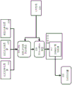
fig. 6 shows a flow chart of a method according to the first embodiment of the first aspect; and
fig. 7 shows a flow chart of a method according to the second embodiment of the first aspect.
Detailed Description
As shown in fig. 1, the device according to the second embodiment of the ninth aspect comprises a plurality of first light sources realized as white LEDs 1a, a plurality of second light sources realized as white LEDs 1b fitted with variable color filters 2 (i.e. color filters 2 adjustable for the emitted color), and a third light source realized as a line light source 3. A projector 9 is provided as a fourth light source for illuminating the structure 7 with structured light. The linear light source is a linear array (one line) of white LEDs connected to at least one arm 4 (the two arms 4 in this example). The at least one arm 4 is driven by a conventional motor, for example a stepper motor, to move over the position of the flat structure 7 so as to illuminate the reflective surface (the upper surface of the structure 7 facing the first, second, third and fourth light sources) in discrete steps representing a quasi-continuous motion. Thereby, the reflective surface can be continuously illuminated with the third type of light. The detection system comprises three digital cameras 5 configured to generate monochromatic (grey scale) image information, which allows detecting luminance values by analyzing image contrast. The structure 7 is arranged on a supporting structure realized as a turntable 6 which is driven in rotation by a stepping motor contained in a base part 8.
As shown in fig. 2, the LEDs 1a,1b, the color filter 2, the camera 5, and the projector 9 are disposed on a holding portion of a dome 10 (i.e., a hemispherical shell) implemented in a dome shape. The dome 10 has an opening so that the light source can shine light onto the structure 7 and the camera 5 to detect a reflected signal from the structure 7. A dome 10 is arranged above the structure 7 for reflection measurements of the structure 7.
As shown in fig. 3, the apparatus according to the third embodiment of the ninth aspect does not include only those features described in the lines of fig. 1 and 2. In addition to this, the device comprises a second holding portion realized by a dome 11 below the structure 7. The turntable 6 is driven by at least one motor (e.g., a stepping motor) 12 (three stepping motors 12 in this example) fixed on a support portion of the turntable 6.
In a first example of the third embodiment of the ninth aspect shown in fig. 4, the second dome 11 is provided with a point light source 1c, which may be a white LED or a colored (spectral) LED or a mixture of both, configured to illuminate the structure 7 from below with point light. Furthermore, the third light source 3 is arranged to be movable under the structure 7. The second dome 11 may also be equipped with other features with which the first dome 10 is provided (e.g. a white LED 1b provided with a colour filter 2, e.g. instead of a colour LED 1c, a projector 9 and possibly an added camera 5). The camera 5 is disposed in the first dome 10, and is located at the other side position of the structure 7 when the structure 7 is viewed from the position of the LED 1 c. The third light source 3 may be provided twice, once in the upper hemisphere above the structure 7 and once in the lower hemisphere below the structure 7. However, it still falls within the framework of the invention that the third light source is provided only once and is arranged such that it can be freely moved (rotated) by the lower and upper hemisphere. In this case, a bearing (the turntable 6) must be provided which is controlled, for example, by at least one drive which is located on the axis of rotation of the third light source 3 and is guided at least in part by at least one arm 4 in order to be able to connect and drive the turntable 6. The camera 5, which is located at the other side position of the structure 7 when the structure 7 is viewed from the position of the LED 1c, again allows transparency and/or translucency measurements to be made of the structure 7.
Fig. 5 shows a second example in a third embodiment of the ninth aspect. Instead of the second dome structure 11, a planar third light source 1d is arranged in the lower hemisphere and on the other side of the structure 7 when the structure 7 is viewed from the position of the camera 5, thereby also allowing translucency and transparency measurements to be made on the structure 7. The planar light source 1d is implemented as a standard LCD display which, if controlled appropriately, is capable of providing both the functionality of the first and second light sources and the third light source in the lower hemisphere. This avoids providing the line light source 3 as an LED array or fluorescent tube and associated drive and holding mechanisms. The line light source 3 may be provided by a display by displaying a linear bright image at predetermined pixel positions. The pixel position can be changed when the structure 7 is illuminated from below, simulating a movement of the position of the line light source 3 along the structure 7 from below. Compared to the arrangement of fig. 1 to 4, the use of a display device, e.g. a display, instead of the other alternatives for the line light source 3 provides greater flexibility and allows for a simplification of the construction of the apparatus. Instead of a display, a large two-dimensional (planar) array of controllable color light emitting diodes (which can emit white light and spectral light) may be used as the planar third light source 1 d.
The flow chart of fig. 6 shows a method according to the first embodiment of the first aspect. Step 101 comprises acquiring first image data describing at least one punctiform light monochromatic image, step 102 comprises acquiring second image data describing at least one punctiform light spectral image, step 103 comprises acquiring third image data describing at least one linear light monochromatic image, and step 104 comprises acquiring fourth image data describing at least one structured light image.
After applying High Dynamic Range (HDR) combining and radiometric correction to the original image, a set of calibrated images of the reflective surfaces of the structure 7 made of a certain material is received. They may be divided into different lighting conditions in the device according to the ninth aspect. On the one hand, there are monochromatic images of the material captured at different positions using the point light sources 1a,1b,1c,1d, the line light sources 3,1d, or there are monochromatic images of the material illuminated by the pattern emitted by the projector 9. On the other hand, there are several color images or spectral images produced using the color filters (filter wheel system) 2. Further, in another example, geometric calibration data for the device may be obtained that contains detailed information for setting up the components for each image. Geometric calibration data is acquired in step 110.
In step 107, the height field of the material is reconstructed from the structured-light image acquired in step 104. First, a dot cloud is generated by using a standard method in the prior art, and the summary of the dot cloud is made by Salvi, J. et al in "Pattern Recognition 43" No.8(2010) pages 2666-2680: "most recent structured light pattern of surface profile", a geometric calibration with pattern images and cameras is used. A height value is then generated for each pixel on the material reference plane, which forms the height field that is acquired as surface geometry data in step 106. For this, all points p of the point cloud are projected perpendicularly to the reference plane and their distance to the plane (their height) is measured. This results in a set of projection coordinates p' and corresponding heights h. For each pixel (x, y) on the reference plane, a k value P ═ P 'near a set of points is collected'i}, utilizingFor corresponding height hiTo generate a height value for (x, y):

where F is the filter kernel. E.g. a Gaussian normal distribution function, and | - |2Is the euclidean distance.
After the height field reconstruction, all other images are projected onto the height field in step 105 in order to align all images in a common coordinate system, which means that the same pixels of all projected images will correspond to the same location on the material surface. Thereby, the reflector mapping data (in particular, the mapping described in the text of the method according to the first aspect) is determined.
The projected image is then provided for SVBRDF fitting, which is contained in step 109, where a set of parameters for a given BRDF model will be found for each pixel (x, y) on the material reference plane. In step 112, a mapping of these parameters is determined, which is then stored, for example, in a digital (electronic) file, and may be fed to the image generation process: i.e. a real-time rendering referred to in step 113, an off-line rendering referred to in step 114 or other processing employed in the method according to the sixth aspect (comparative measurements for quality control of the optical properties of the material in step 115). When determining the reflectivity distribution data, the processing of step 109 can eliminate the effect of the fixed illumination geometry of the device and the specific geometry of the structure 7 (in particular the reflecting surface).
For real-time rendering, the delineation of self-shadows within the material may also be extracted from the projected image by looking up the per-pixel parameters of the shadow model in step 108, where the real-time shadow model is stored in the second map in the digital file in step 111.
SVBRDF fitting
The SVBRDF fitting process in step 109 can be roughly divided into two stages. In the first phase, data is prepared and in the second phase, the BRDF model parameters per pixel are found by a fitting process. The BRDF fitting process differs from previously published fitting processes in that it distinguishes the fit of the BRDF 4D "shape" from the fit of the "color" component of the model to account for sparse color information.
The first stage begins with the calculation of monochrome information from the available color samples. This requires knowledge about the spectral response of the capture system (detection system). In the case of spectral samples, this involves calculating a convolution of all image spectra with the spectral system response of the monochromatic imaging portion. In the case of a three-color image, a 1 × 3 matrix is calculated based on spectral responses corresponding to a three-color space, spectral system responses of a monochrome imaging section, and some exercise data. Then, a monochrome image is calculated by left-multiplying the matrix to all color vectors (pixels) of the color image.
Second, a set of pixels is selected for a butt fit of the BRDF parameters. In the simplest case, this can consist of only a single pixel at a time. However, clustering techniques may also be used to group pixels according to their appearance. This helps to stabilize the fit, after which more data can be acquired during the fitting phase.
In a further (final) step, the preparation phase comprises extracting the data value corresponding to the selected pixel. In this regard, the pixel values of each pixel are extracted from the image, and the geometric calibration and height fields are then used to calculate the position of the light source and sensor relative to the individual pixels.
This data is then fed to the second stage where an actual BRDF fit (fitting of the bi-directional reflectance distribution function parameters) is performed. This involves fitting of a monochromatic BRDF, followed by "coloring" the monochromatic BRDF. The result of this process is: a set of parameters per pixel (which includes the surface normal vector), the specular parameters of the model, and the color values of the BRDF model.
Monochromatic BRDF fitting
Fitting of a monochromatic BRDF model can be seen as an energy minimization problem, where an attempt is made to find a set of parameters for the BRDF model in such a way that: that is, simulation of the measured material using the BRDF model can match the measured value to the minimum error that results from measuring with a certain distance. However, when trying to solve this problem in a straightforward manner, the challenges encountered are: the resulting energy function may have a number of local minima, where all practical algorithms are easily unable to proceed. For this reason, good initialization of the BRDF model parameters is required to start optimization as close to optimal results as possible. Furthermore, it is mandatory to limit the optimizer to certain decreasing directions in the parameter space at one moment in time.
The scheme included in the disclosed method begins with the initialization of a closed form of surface normal and diffuse reflectance (diffuse "color" for a monochromatic BRDF). For extremely matt materials, this is done using the well-known photometric stereo technique published in "photometric stereo" published by Woodham, Rober J in the 22 nd SPIE conference record 0155 "image understanding system and industrial applications I" 136(1979, 1/9 th): one type of determining the orientation of a surface based on image intensity is a reflection mapping technique ". For more specular material, the maximum measurement produced by the linear light source illumination is searched for all rotation angles of the sample. Assuming perfect specular material is present, the normal vector can be calculated from the law of reflection. The user may select an appropriate algorithm. A complete initialization of the per-pixel parameters is obtained by setting the mirror color to zero and the mirror parameters to some average value (depending on the model used).
After this initialization, the parameters and data are fed into a main optimization loop consisting of only diffuse and specular parameters, followed by an optimization of only the normal vector. Thereafter, a convergence check is performed. The algorithm is terminated if the error obtained in the last step decreases below a given (e.g., predetermined or user-specified) threshold. Otherwise, the loop starts again.
Fitting procedure
Optimization of specular and diffuse parameters and normal vectors proceeds in the same manner, although constraints are placed on the optimization of the subset of parameters per pixel parameter. An optimization loop is employed in which the first step is to synthesize measurements from a given set of per-pixel parameters. This is essentially a simulation of the measurement device for virtual materials. Technically, this is done by resolving the rendering equation for each pixel and each lighting condition considered. Rendering equations are disclosed, for example, in Kajiya, James T, in the United states computer society, 1986, "ACM SIGGRAPH (American computer science, computer graphics image Special interest group) computer graphics", Vol.20, No.4, p.143-. To this end, a virtual scene is constructed from the calibration, and the emergent radiation in the sensor direction is calculated as follows:

where x is the position on the surface, ωoIs the direction of emission, LeIs the radiation emitted by the surface, omega is the local hemisphere above the point x, omegaiIs the direction of incident light, nxIs the local surface normal at x, ρ is the selected BRDF model, and ρ isxIs a set of pixel parameters. Equation (2) is recursive in that it is oriented in the direction ωiIncident radiation L at point x' in the scene can be seeni(x,ωi) Equal to the emergent radiation Lo(x’,-ωi)。
To simplify the synthesis process, the method only considers the first level of recursion, i.e. only assumes direct illumination. The virtual material is assumed to be the only reflecting surface in the scene and the light source is the only light emitting surface. When the light source is also diverged into a set of n point light sources, the rendering equation will be reduced to:

wherein L isijIs the radiation emitted by the j point source, and ωijIn its direction.
After the radiation value is calculated, the calculated radiation value is compared with the measured radiation value, and an error value is calculated. The error function may be, for example, a relative error or an L1 error.
Thereafter, the optimization is checked for convergence. The algorithm is terminated if the decrease in error value between the last iteration and the current iteration is below a threshold, or if a given total number of iterations is reached. Otherwise, a new set of parameters is calculated based on the old set of parameters to reduce the error function. This is done using standard methods such as gradient descent and may require additional forward synthetic evaluation and error evaluation in order to numerically calculate the gradient of the error function. After the parameters improve, the next iteration starts.
Color fitting
The final part of the overall algorithm according to the method of the invention is to determine the color of the monochromatic BRDF. The first step is to calculate the specular color from the monochromatic specular part. For dielectric materials, this is done by copying the monochrome values into all color channels, since these materials have a white highlight. Different strategies may be employed for metal or other conductors, for example combining prior knowledge about the material classes.
Thereafter, the specular portion is deleted from all measured values to end up with a color value containing only diffuse reflection color information. To this end, the forward synthesis in the previous step, for example, is calculated only in conjunction with the specular part of the BRDF model. The resulting synthesized specular color is then subtracted from the measured color values.
In a further (final) step, these color values are input to a diffuse reflectance color fit. This is calculated as a linear least squares problem for each color channel. In the simplest case, the error function can be formulated as:

where N is the number of color samples, diIs the diffuse reflectance color value of channel i, mi,jIs the measured specular free diffuse reflectance value of channel i, and wjIs the weight of sample j. The weight may be calculated based on multiple considerationsSuch as the angular distance of the sample from the specular highlight, or the saturation of the measured color. When fitting colors in XYZ color space (rather than spectra), a well-known linear approximation of Δ E may be used to fit perceptually closer colors. In addition, the RANSAC algorithm can be used to remove outliers.
Shadow fitting
In an off-line rendering method like ray tracing in step 114, the correct self-shading can be generated inside the material by reconstructing the height field in step 108. However, this approach is not directly applicable in the real-time rendering application involved in step 113. Of course, techniques such as shadow mapping may be used, but the resulting shadows are rather rough and unnatural.
To generate real-time self-shadows, the method of the invention formulates a second function for each location on the surface of the material, which describes the attenuation versus direction of incident light. The self-shading is derived by comparing the values of the respective pixels of the projected spot input image with the resultant values generated by forward synthesis using the final BRDF parameters for the same pixels. The ratio of the mean or difference of the two values per illumination direction can be used to express the self-shadowing effect.
To model the shading values depending on the illumination direction, smooth hemispherical functions may be used, such as the spherical harmonic functions disclosed by Sloan, Peter-Pike et al in ACM trading graphics (TOG) 2002, volume 21, 34, p 527-536, "Pre-computed radiation Transmission for real-time rendering in dynamic Low-frequency Lighting environments", or the polynomial texture mapping disclosed by Malzrender, Tom et al in computer science 2001, p 28-year computer graphics and interaction technology, p 519-528. However, since the method of the present invention obtains very regular hemispherical sampling by point light sources, and since the inventors found that the above method shows artifacts when the grazing angle is estimated, it has led to a different strategy: in step 111 a small two-dimensional table is stored per pixel, comprising for example 4 x 4 entries parameterizing the two-dimensional projection of the illuminated hemisphere. The entries of this table are calculated by filtering the samples in angular space. At the reconstruction time, a two-dimensional linear interpolation is performed. This method has a constant extrapolation for grazing illumination angles (large angles of incidence) and has an interpolation between sample points comparable to the prior art method, although consuming only a little more memory per pixel compared to the prior art. For rendering at the level of detail, a spatially down-sampled version of the table may be pre-computed.
Fig. 7 shows a second embodiment of the method according to the first aspect, which is used according to the sixth aspect. In step 206, instead of using the height field, a normal field is required as geometry data, and in step 205, the reflector mapping data is determined by projecting an image rendered by the first image data, the second image data and the third image data onto the normal field. The remaining steps shown in fig. 7, having the same designation as the remaining steps shown in fig. 6, contain the same data processing functions as the corresponding steps shown and described above with reference to fig. 6.
Claims (14)
1. A digital data processing method for determining data representing a mapping of an optical signal described by image data of a reflecting surface of a structure (7) to a three-dimensional surface geometry of the reflecting surface, the method comprising the following steps formulated to be executed by a computer:
a) acquiring (101) first image data describing a reflection image of a broadband point source from the reflection surface;
b) acquiring (102) second image data, the second image data describing a reflection image of a spectrally variable point source from the reflective surface;
c) moving the arm and acquiring (103) third image data describing a reflected image of a linear broadband light source mounted on the arm from the reflective surface;
d) acquiring (106,206) surface geometry data, the surface geometry data describing a three-dimensional surface geometry of the reflecting surface; and
e) based on the first, second, third and surface geometry data, determining (105,205) reflector mapping data describing a mapping between reflections described by the first, second and third image data and a three-dimensional surface geometry of the reflector.
2. The method of claim 1, wherein the surface geometry data describes a height field of the reflecting surface.
3. The method of claim 2, comprising:
acquiring (104) fourth image data, the fourth image data describing a light reflection image of the structured light,
wherein the surface geometry data is acquired (106,206) based on the fourth image data.
4. The method of claim 1, wherein the surface geometry data describes at least one of a height field and a normal field of the reflecting surface.
5. The method as recited in claim 4, wherein the surface geometry data describes a normal field of the reflecting surface and the surface geometry data is acquired (106,206) based on at least one of the first image data, second image data, and third image data.
6. A method for determining data describing a spatially varying bi-directional reflectivity distribution of a reflective surface of a structure (7), the method comprising the following steps made to be executed by a computer:
performing the method according to any one of the preceding claims;
obtaining reflectance function data describing a bi-directional reflectance distribution function model; and
determining reflectivity distribution data describing a spatially varying bi-directional reflectivity distribution of the reflective surface based on the reflective surface mapping data and the reflectivity function data.
7. A method of off-line rendering of a digital image representation of a reflective surface of a structure (7), the method comprising the following steps made to be executed by a computer:
performing the method of claim 6;
determining surface representation data describing an image of the reflective surface based on the reflectance distribution data and at least one of the first image data, second image data, and third image data; and
-rendering (114) the information content of the surface representation data offline on a display device.
8. A method for determining data describing the shadow appearance of a reflective surface of a structure (7), the method comprising the following steps made to be executed by a computer:
performing the method of claim 6; and
determining (108) shadow appearance data describing a model and parameters defining a shadow appearance of the reflective surface based on the reflective surface mapping data and at least one of the first image data, second image data and third image data.
9. A method of rendering a digital image representation of a reflecting surface of a structure in real time, the method comprising the steps formulated for execution by a computer of:
performing the method of any one of claims 6 to 8;
determining surface representation data describing an image of the reflective surface based on the reflectivity profile data; and
rendering (113) the information content of the surface representation data in real time on a display device.
10. A computer program which, when run on a computer or loaded onto a computer, causes the computer to perform a method according to any preceding claim.
11. A non-transitory computer readable storage medium on which the computer program according to claim 10 is stored.
12. An apparatus for acquiring data representative of an optical signal received from a reflective surface of a structure (7), comprising:
a) at least one first light source (1a) comprising a broadband point light source oriented towards said reflective surface;
b) at least one second light source (1b,2) comprising a spectrally variable point light source oriented towards said reflective surface;
c) at least one third light source (3) comprising a linear broadband light source mounted on the movable arm and oriented towards the reflecting surface;
d) a dome surrounding the movable arm and at least one third light source;
e) a support (6) for supporting the structure (7) enclosed within the dome;
f) a detection system (5) configured to:
detecting a first reflection signal from a first light source of the reflecting surface and converting the first reflection signal into first image data describing an image of the reflecting surface of the structure (7);
detecting at least one second reflection signal from a second light source of the reflecting surface and converting the second reflection signal into second image data describing an image of the reflecting surface of the structure (7); and
detecting at least one third reflection signal from a third light source of the reflecting surface and converting the third reflection signal into third image data describing an image of the reflecting surface of the structure (7);
g) computer operatively connected to the detection system (5) and configured to execute the computer program according to claim 10, and/or comprising the storage medium according to claim 11.
13. The device of claim 12, comprising:
at least one fourth light source (9) comprising a structured light source oriented towards said reflective surface;
wherein the detection system (5) is configured to detect a fourth reflection signal from the fourth light source of the structure (7) and to convert the fourth reflection signal into surface geometry data describing a height field of the structure (7).
14. The device according to claim 13, wherein the detection system (5) and the first (1a), second (1b,2), third (1d,3) and fourth (9) light sources are arranged in a dome above the support (6) and at least one other light source (1d,3) is arranged in a hemisphere below the support (6).
Applications Claiming Priority (2)
| Application Number | Priority Date | Filing Date | Title |
|---|---|---|---|
| EP14197409.7A EP3032241B1 (en) | 2014-12-11 | 2014-12-11 | Method and apparatus for digitizing the appearance of a real material |
| EP14197409.7 | 2014-12-11 |
Publications (2)
| Publication Number | Publication Date |
|---|---|
| CN105701793A CN105701793A (en) | 2016-06-22 |
| CN105701793B true CN105701793B (en) | 2021-05-28 |
Family
ID=52302047
Family Applications (1)
| Application Number | Title | Priority Date | Filing Date |
|---|---|---|---|
| CN201510917597.0A Active CN105701793B (en) | 2014-12-11 | 2015-12-10 | Method and apparatus for digitizing the appearance of real materials |
Country Status (5)
| Country | Link |
|---|---|
| US (2) | US10026215B2 (en) |
| EP (1) | EP3032241B1 (en) |
| JP (1) | JP6661336B2 (en) |
| CN (1) | CN105701793B (en) |
| DE (1) | DE202015102081U1 (en) |
Families Citing this family (21)
| Publication number | Priority date | Publication date | Assignee | Title |
|---|---|---|---|---|
| JP6604744B2 (en) * | 2015-05-03 | 2019-11-13 | キヤノン株式会社 | Image processing apparatus, image processing method, image forming system, and program |
| US10564096B2 (en) * | 2015-09-14 | 2020-02-18 | University Of Florida Research Foundation, Incorporated | Method for measuring bi-directional reflectance distribution function (BRDF) and associated device |
| US20170109895A1 (en) * | 2015-10-19 | 2017-04-20 | Honeywell International Inc. | Apparatus and method for measuring haze of sheet materials or other materials using off-axis detector |
| US11170514B2 (en) * | 2015-10-27 | 2021-11-09 | Canon Kabushiki Kaisha | Image processing apparatus, image processing method, 3D printing system, and storage medium |
| CZ307214B6 (en) * | 2016-11-30 | 2018-03-28 | České vysoké učenà technické v Praze | A portable device for measuring object geometry and spatially variable reflection functions on sample surface with multiplication of elements involved in imaging and scanning systems on moving arms allowing for field measurements |
| US10636140B2 (en) * | 2017-05-18 | 2020-04-28 | Applied Materials Israel Ltd. | Technique for inspecting semiconductor wafers |
| JP6950544B2 (en) * | 2018-01-17 | 2021-10-13 | トヨタ自動車株式会社 | Simulation equipment, reflection characteristic estimation method, and program |
| US11209360B2 (en) | 2018-03-16 | 2021-12-28 | Konica Minolta, Inc. | Color tone quantification device for glossy color, color tone measurement device for glossy color and color tone quantification method for glossy color |
| US10740954B2 (en) | 2018-03-17 | 2020-08-11 | Nvidia Corporation | Shadow denoising in ray-tracing applications |
| US11436791B2 (en) * | 2018-04-30 | 2022-09-06 | The Regents Of The University Of California | Methods and systems for acquiring svBRDF measurements |
| JP7087687B2 (en) * | 2018-06-01 | 2022-06-21 | 株式会社サタケ | Grain gloss measuring device |
| KR102599207B1 (en) * | 2018-07-20 | 2023-12-15 | 삼성전자 주식회사 | Apparatus and method for measuring surface of electronic device |
| US10991079B2 (en) | 2018-08-14 | 2021-04-27 | Nvidia Corporation | Using previously rendered scene frames to reduce pixel noise |
| US10883823B2 (en) | 2018-10-18 | 2021-01-05 | Cyberoptics Corporation | Three-dimensional sensor with counterposed channels |
| US11295969B2 (en) | 2018-11-27 | 2022-04-05 | International Business Machines Corporation | Hybridization for characterization and metrology |
| US11480868B2 (en) | 2019-03-22 | 2022-10-25 | International Business Machines Corporation | Determination of optical roughness in EUV structures |
| US20220364852A1 (en) * | 2019-06-28 | 2022-11-17 | Koh Young Technology Inc. | Apparatus and method for determining three-dimensional shape of object |
| US10805549B1 (en) * | 2019-08-20 | 2020-10-13 | Himax Technologies Limited | Method and apparatus of auto exposure control based on pattern detection in depth sensing system |
| JP7411928B2 (en) | 2019-12-26 | 2024-01-12 | 株式会社Rutilea | Item photography device |
| JP7412610B2 (en) * | 2020-06-29 | 2024-01-12 | ビーエーエスエフ コーティングス ゲゼルシャフト ミット ベシュレンクテル ハフツング | Using bidirectional texture functions |
| CN113138027A (en) * | 2021-05-07 | 2021-07-20 | 东南大学 | Far infrared non-vision object positioning method based on bidirectional refractive index distribution function |
Citations (6)
| Publication number | Priority date | Publication date | Assignee | Title |
|---|---|---|---|---|
| EP0452905A1 (en) * | 1990-04-18 | 1991-10-23 | Hitachi, Ltd. | Method and apparatus for inspecting surface pattern of object |
| CN1364230A (en) * | 1999-06-01 | 2002-08-14 | 加拿大国家研究委员会 | Three dimensional optical scanning |
| US20030231174A1 (en) * | 2002-06-17 | 2003-12-18 | Wojciech Matusik | Modeling and rendering of surface reflectance fields of 3D objects |
| US20080232679A1 (en) * | 2005-08-17 | 2008-09-25 | Hahn Daniel V | Apparatus and Method for 3-Dimensional Scanning of an Object |
| CN103649677A (en) * | 2011-07-13 | 2014-03-19 | 法罗技术股份有限公司 | Device and method using a spatial light modulator to find 3D coordinates of an object |
| WO2014091214A1 (en) * | 2012-12-12 | 2014-06-19 | The University Of Birmingham | Surface geometry imaging |
Family Cites Families (14)
| Publication number | Priority date | Publication date | Assignee | Title |
|---|---|---|---|---|
| US2353512A (en) * | 1943-05-05 | 1944-07-11 | Simmon Alfred | Photographic enlarger |
| DE1489395B2 (en) * | 1965-06-01 | 1971-07-22 | Maehler & Kaege Elektrotechnische Spezialfabnk AG, 6507 Ingelheim | DIMMABLE INDICATOR LIGHT |
| US5710876A (en) * | 1995-05-25 | 1998-01-20 | Silicon Graphics, Inc. | Computer graphics system for rendering images using full spectral illumination data |
| US6084663A (en) * | 1997-04-07 | 2000-07-04 | Hewlett-Packard Company | Method and an apparatus for inspection of a printed circuit board assembly |
| GB9911266D0 (en) * | 1999-05-15 | 1999-07-14 | Metcalfe Nicholas | Display apparatus |
| US6950104B1 (en) * | 2000-08-30 | 2005-09-27 | Microsoft Corporation | Methods and systems for animating facial features, and methods and systems for expression transformation |
| US7102647B2 (en) * | 2001-06-26 | 2006-09-05 | Microsoft Corporation | Interactive horizon mapping |
| JP4335589B2 (en) * | 2002-06-27 | 2009-09-30 | ミツビシ・エレクトリック・リサーチ・ラボラトリーズ・インコーポレイテッド | How to model a 3D object |
| US7940396B2 (en) * | 2005-04-25 | 2011-05-10 | X-Rite, Inc. | Measuring an appearance property of a surface using a spatially under-sampled bidirectional reflectance distribution function |
| JP5251678B2 (en) * | 2009-03-31 | 2013-07-31 | ソニー株式会社 | Illumination device for visual inspection and visual inspection device |
| CN101901302A (en) * | 2010-07-16 | 2010-12-01 | 中国人民解放军信息工程大学 | Light scattering modeling method for complex spatial object |
| CN102175012A (en) * | 2011-03-17 | 2011-09-07 | 赵景琪 | Light source adjusting device |
| US9562857B2 (en) * | 2013-03-14 | 2017-02-07 | University Of Southern California | Specular object scanner for measuring reflectance properties of objects |
| US20150032430A1 (en) | 2013-07-29 | 2015-01-29 | X-Rite Europe Gmbh | Visualization Method |
-
2014
- 2014-12-11 EP EP14197409.7A patent/EP3032241B1/en active Active
-
2015
- 2015-03-30 US US14/673,312 patent/US10026215B2/en active Active
- 2015-04-27 DE DE202015102081.3U patent/DE202015102081U1/en active Active
- 2015-11-18 JP JP2015225385A patent/JP6661336B2/en active Active
- 2015-12-10 CN CN201510917597.0A patent/CN105701793B/en active Active
-
2018
- 2018-07-13 US US16/034,515 patent/US10332306B2/en active Active
Patent Citations (6)
| Publication number | Priority date | Publication date | Assignee | Title |
|---|---|---|---|---|
| EP0452905A1 (en) * | 1990-04-18 | 1991-10-23 | Hitachi, Ltd. | Method and apparatus for inspecting surface pattern of object |
| CN1364230A (en) * | 1999-06-01 | 2002-08-14 | 加拿大国家研究委员会 | Three dimensional optical scanning |
| US20030231174A1 (en) * | 2002-06-17 | 2003-12-18 | Wojciech Matusik | Modeling and rendering of surface reflectance fields of 3D objects |
| US20080232679A1 (en) * | 2005-08-17 | 2008-09-25 | Hahn Daniel V | Apparatus and Method for 3-Dimensional Scanning of an Object |
| CN103649677A (en) * | 2011-07-13 | 2014-03-19 | 法罗技术股份有限公司 | Device and method using a spatial light modulator to find 3D coordinates of an object |
| WO2014091214A1 (en) * | 2012-12-12 | 2014-06-19 | The University Of Birmingham | Surface geometry imaging |
Non-Patent Citations (1)
| Title |
|---|
| 《DOME II:A Parallelized BTF Acquisition System》;SCHWARTZ,C.et al.;《PROCEEDINGS OF EUROGRAPHICS WORKSHOP ON MATERIAL APPEARANCE MODELING:ISSUES AND ACQUISITION》;20130630;第25页第1段-27页第2段,第28页,图1 * |
Also Published As
| Publication number | Publication date |
|---|---|
| CN105701793A (en) | 2016-06-22 |
| JP2016114598A (en) | 2016-06-23 |
| EP3032241A1 (en) | 2016-06-15 |
| US10332306B2 (en) | 2019-06-25 |
| US20160171748A1 (en) | 2016-06-16 |
| EP3032241B1 (en) | 2023-03-01 |
| JP6661336B2 (en) | 2020-03-11 |
| DE202015102081U1 (en) | 2016-03-17 |
| US10026215B2 (en) | 2018-07-17 |
| US20180322686A1 (en) | 2018-11-08 |
Similar Documents
| Publication | Publication Date | Title |
|---|---|---|
| CN105701793B (en) | Method and apparatus for digitizing the appearance of real materials | |
| JP6407607B2 (en) | Method and apparatus for digitally generating appearance data | |
| US6831641B2 (en) | Modeling and rendering of surface reflectance fields of 3D objects | |
| JP4335588B2 (en) | How to model a 3D object | |
| EP3051793B1 (en) | Imaging apparatus, systems and methods | |
| US20030231175A1 (en) | Image-based 3D modeling rendering system | |
| JP7027807B2 (en) | Display devices, scanners, display systems and programs | |
| Sitnik et al. | Archiving shape and appearance of cultural heritage objects using structured light projection and multispectral imaging | |
| Pitard et al. | Discrete modal decomposition for surface appearance modelling and rendering | |
| Ciortan et al. | A practical reflectance transformation imaging pipeline for surface characterization in cultural heritage | |
| KR20210011966A (en) | Dental 3D scanner using angle-based tone matching | |
| Castro et al. | A new method for calibration of the spatial distribution of light positions in free-form RTI acquisitions | |
| Guarnera et al. | Material capture and representation with applications in virtual reality | |
| US20230343051A1 (en) | Visualizing the appearances of at least two materials | |
| KR102171773B1 (en) | Inspection area determination method and visual inspection apparatus using the same | |
| Guarnera et al. | Virtual material acquisition and representation for computer graphics | |
| US20230260193A1 (en) | Generating a destination texture from a plurality of source textures | |
| US20230260237A1 (en) | Visualizing the appearance of at least two materials | |
| Eilertsen et al. | A versatile material reflectance measurement system for use in production | |
| Sitnik et al. | Integrated shape, color, and reflectivity measurement method for 3D digitization of cultural heritage objects | |
| Guarnera et al. | BxDF material acquisition, representation, and rendering for VR and design | |
| Ladefoged et al. | Spatially-varying diffuse reflectance capture using irradiance map rendering for image-based modeling applications | |
| Padhye | Techniques to Create a Realistic Digital Collection of Near Planar Cultural Heritage Objects | |
| WO2023131863A1 (en) | Method, computer and computer program for modifying texture images | |
| JP6379651B2 (en) | Apparatus, method, and program for measuring light distribution of light source and bidirectional reflectance distribution function of object |
Legal Events
| Date | Code | Title | Description |
|---|---|---|---|
| C06 | Publication | ||
| PB01 | Publication | ||
| SE01 | Entry into force of request for substantive examination | ||
| SE01 | Entry into force of request for substantive examination | ||
| GR01 | Patent grant | ||
| GR01 | Patent grant |