CN1056268A - Combined small ferrous rolling mill and rod-rolling mill machine row - Google Patents
Combined small ferrous rolling mill and rod-rolling mill machine row Download PDFInfo
- Publication number
- CN1056268A CN1056268A CN91102780A CN91102780A CN1056268A CN 1056268 A CN1056268 A CN 1056268A CN 91102780 A CN91102780 A CN 91102780A CN 91102780 A CN91102780 A CN 91102780A CN 1056268 A CN1056268 A CN 1056268A
- Authority
- CN
- China
- Prior art keywords
- collars
- rolling mill
- rod
- machine row
- described light
- Prior art date
- Legal status (The legal status is an assumption and is not a legal conclusion. Google has not performed a legal analysis and makes no representation as to the accuracy of the status listed.)
- Pending
Links
- 238000005096 rolling process Methods 0.000 title claims abstract description 59
- CWYNVVGOOAEACU-UHFFFAOYSA-N Fe2+ Chemical compound [Fe+2] CWYNVVGOOAEACU-UHFFFAOYSA-N 0.000 title claims description 6
- 238000003801 milling Methods 0.000 claims abstract description 21
- 230000005540 biological transmission Effects 0.000 claims abstract description 20
- 230000009471 action Effects 0.000 claims abstract description 4
- 238000001816 cooling Methods 0.000 claims description 5
- 239000000463 material Substances 0.000 claims description 5
- 238000012545 processing Methods 0.000 claims description 4
- 230000003044 adaptive effect Effects 0.000 claims description 3
- 230000000694 effects Effects 0.000 claims description 3
- 238000009434 installation Methods 0.000 abstract description 2
- 238000004519 manufacturing process Methods 0.000 description 5
- 230000008859 change Effects 0.000 description 3
- 238000013461 design Methods 0.000 description 3
- 238000007493 shaping process Methods 0.000 description 3
- 229910000831 Steel Inorganic materials 0.000 description 2
- 230000006835 compression Effects 0.000 description 2
- 238000007906 compression Methods 0.000 description 2
- 230000006837 decompression Effects 0.000 description 2
- 239000010959 steel Substances 0.000 description 2
- 238000005299 abrasion Methods 0.000 description 1
- 230000008901 benefit Effects 0.000 description 1
- 238000010276 construction Methods 0.000 description 1
- 238000011161 development Methods 0.000 description 1
- 238000005516 engineering process Methods 0.000 description 1
- 230000002349 favourable effect Effects 0.000 description 1
- 230000005484 gravity Effects 0.000 description 1
- 238000012423 maintenance Methods 0.000 description 1
- 230000005012 migration Effects 0.000 description 1
- 238000013508 migration Methods 0.000 description 1
- 230000008520 organization Effects 0.000 description 1
- 238000005498 polishing Methods 0.000 description 1
- 238000003825 pressing Methods 0.000 description 1
- 230000003014 reinforcing effect Effects 0.000 description 1
- 238000012857 repacking Methods 0.000 description 1
- 230000008439 repair process Effects 0.000 description 1
- 238000003860 storage Methods 0.000 description 1
- 230000001360 synchronised effect Effects 0.000 description 1
Images

Classifications
-
- B—PERFORMING OPERATIONS; TRANSPORTING
- B21—MECHANICAL METAL-WORKING WITHOUT ESSENTIALLY REMOVING MATERIAL; PUNCHING METAL
- B21B—ROLLING OF METAL
- B21B27/00—Rolls, roll alloys or roll fabrication; Lubricating, cooling or heating rolls while in use
- B21B27/02—Shape or construction of rolls
- B21B27/03—Sleeved rolls
- B21B27/035—Rolls for bars, rods, rounds, tubes, wire or the like
-
- B—PERFORMING OPERATIONS; TRANSPORTING
- B21—MECHANICAL METAL-WORKING WITHOUT ESSENTIALLY REMOVING MATERIAL; PUNCHING METAL
- B21B—ROLLING OF METAL
- B21B1/00—Metal-rolling methods or mills for making semi-finished products of solid or profiled cross-section; Sequence of operations in milling trains; Layout of rolling-mill plant, e.g. grouping of stands; Succession of passes or of sectional pass alternations
- B21B1/16—Metal-rolling methods or mills for making semi-finished products of solid or profiled cross-section; Sequence of operations in milling trains; Layout of rolling-mill plant, e.g. grouping of stands; Succession of passes or of sectional pass alternations for rolling wire rods, bars, merchant bars, rounds wire or material of like small cross-section
- B21B1/18—Metal-rolling methods or mills for making semi-finished products of solid or profiled cross-section; Sequence of operations in milling trains; Layout of rolling-mill plant, e.g. grouping of stands; Succession of passes or of sectional pass alternations for rolling wire rods, bars, merchant bars, rounds wire or material of like small cross-section in a continuous process
-
- B—PERFORMING OPERATIONS; TRANSPORTING
- B21—MECHANICAL METAL-WORKING WITHOUT ESSENTIALLY REMOVING MATERIAL; PUNCHING METAL
- B21B—ROLLING OF METAL
- B21B31/00—Rolling stand structures; Mounting, adjusting, or interchanging rolls, roll mountings, or stand frames
- B21B31/08—Interchanging rolls, roll mountings, or stand frames, e.g. using C-hooks; Replacing roll chocks on roll shafts
-
- B—PERFORMING OPERATIONS; TRANSPORTING
- B21—MECHANICAL METAL-WORKING WITHOUT ESSENTIALLY REMOVING MATERIAL; PUNCHING METAL
- B21B—ROLLING OF METAL
- B21B1/00—Metal-rolling methods or mills for making semi-finished products of solid or profiled cross-section; Sequence of operations in milling trains; Layout of rolling-mill plant, e.g. grouping of stands; Succession of passes or of sectional pass alternations
- B21B1/08—Metal-rolling methods or mills for making semi-finished products of solid or profiled cross-section; Sequence of operations in milling trains; Layout of rolling-mill plant, e.g. grouping of stands; Succession of passes or of sectional pass alternations for rolling structural sections, i.e. work of special cross-section, e.g. angle steel
- B21B1/12—Metal-rolling methods or mills for making semi-finished products of solid or profiled cross-section; Sequence of operations in milling trains; Layout of rolling-mill plant, e.g. grouping of stands; Succession of passes or of sectional pass alternations for rolling structural sections, i.e. work of special cross-section, e.g. angle steel in a continuous process, i.e. without reversing stands
-
- B—PERFORMING OPERATIONS; TRANSPORTING
- B21—MECHANICAL METAL-WORKING WITHOUT ESSENTIALLY REMOVING MATERIAL; PUNCHING METAL
- B21B—ROLLING OF METAL
- B21B13/00—Metal-rolling stands, i.e. an assembly composed of a stand frame, rolls, and accessories
- B21B13/001—Convertible or tiltable stands, e.g. from duo to universal stands, from horizontal to vertical stands
-
- B—PERFORMING OPERATIONS; TRANSPORTING
- B21—MECHANICAL METAL-WORKING WITHOUT ESSENTIALLY REMOVING MATERIAL; PUNCHING METAL
- B21B—ROLLING OF METAL
- B21B13/00—Metal-rolling stands, i.e. an assembly composed of a stand frame, rolls, and accessories
- B21B13/005—Cantilevered roll stands
-
- B—PERFORMING OPERATIONS; TRANSPORTING
- B21—MECHANICAL METAL-WORKING WITHOUT ESSENTIALLY REMOVING MATERIAL; PUNCHING METAL
- B21B—ROLLING OF METAL
- B21B13/00—Metal-rolling stands, i.e. an assembly composed of a stand frame, rolls, and accessories
- B21B2013/006—Multiple strand rolling mills; Mill stands with multiple caliber rolls
-
- B—PERFORMING OPERATIONS; TRANSPORTING
- B21—MECHANICAL METAL-WORKING WITHOUT ESSENTIALLY REMOVING MATERIAL; PUNCHING METAL
- B21B—ROLLING OF METAL
- B21B27/00—Rolls, roll alloys or roll fabrication; Lubricating, cooling or heating rolls while in use
- B21B27/06—Lubricating, cooling or heating rolls
- B21B27/10—Lubricating, cooling or heating rolls externally
- B21B2027/103—Lubricating, cooling or heating rolls externally cooling externally
-
- B—PERFORMING OPERATIONS; TRANSPORTING
- B21—MECHANICAL METAL-WORKING WITHOUT ESSENTIALLY REMOVING MATERIAL; PUNCHING METAL
- B21B—ROLLING OF METAL
- B21B2203/00—Auxiliary arrangements, devices or methods in combination with rolling mills or rolling methods
- B21B2203/06—Cassettes
-
- B—PERFORMING OPERATIONS; TRANSPORTING
- B21—MECHANICAL METAL-WORKING WITHOUT ESSENTIALLY REMOVING MATERIAL; PUNCHING METAL
- B21B—ROLLING OF METAL
- B21B31/00—Rolling stand structures; Mounting, adjusting, or interchanging rolls, roll mountings, or stand frames
- B21B31/16—Adjusting or positioning rolls
- B21B31/20—Adjusting or positioning rolls by moving rolls perpendicularly to roll axis
- B21B31/22—Adjusting or positioning rolls by moving rolls perpendicularly to roll axis mechanically, e.g. by thrust blocks, inserts for removal
- B21B31/26—Adjusting eccentrically-mounted roll bearings
Landscapes
- Engineering & Computer Science (AREA)
- Mechanical Engineering (AREA)
- Physics & Mathematics (AREA)
- Geometry (AREA)
- Reduction Rolling/Reduction Stand/Operation Of Reduction Machine (AREA)
- Metal Rolling (AREA)
- Superconductors And Manufacturing Methods Therefor (AREA)
- Ropes Or Cables (AREA)
- Treatment Of Steel In Its Molten State (AREA)
Abstract
A kind of light shape milling train of combined type continuous operation and rod-rolling mill machine row mainly are made of the suspend cantilever frame of collars of band, are provided with the mill stand of several band double base collars adjustment units in roughing train and middle machine row and/or finishing mill line.Be with the CL frame adjustment unit of the collars that suspends to replace by the adjustment unit of band double base collars.Second bearing of adjustment unit be located at one with the pieceable cramp frame of CL frame transmission clamping frame in, collars is by an automatically control, preferably the quick-speed jigs with hydraulic action carries out installation and dismantling, these anchor clamps by piston-cylinder tube unit make collars on axle vertically and radially clamp and loosen.
Description
The present invention relates to a kind of high-efficiency small-sized ferrous rolling mill and rod-rolling mill machine row of combined type continuous operation, the roughing train that respectively has a plurality of mill stands or roll unit has in the middle of one machine row and the finishing mill line that is connected at least together with the final processing section that may be used for the back.
According to a undocumented patent application P 3940236.5, the described mill train of a kind of beginning is proposed, finish roll change according to miniaturization pass schedule standard in each machine row section, wherein use lifting gear in the roughing train, use in the middle machine row manipulation machine in finishing mill line then by quick replacement device in case of necessity again the additional manipulation machine finish roll change, wherein all mill stands of each machine row section or roll unit all have and suspend and dismountable roll, to improve the practicality and the productivity ratio of mill train.The mill stand that has the collars that suspends is known as the cantilever frame or is called for short the CL frame in relevant technical term.Therefore its feature of compact rack construction in this modern times is exactly the roll mandrel that suspends.The collars that high abrasion damage material is made has guaranteed permanent pass durability.Vertical Rack starts from the below, is provided with a preposition transmission device between engine and frame, and this device is to be arranged to the beveled spur gear transmission device in Vertical Rack, then is spur gearing in horizontal framework.In rolling-mill housing, driving shaft in addition drive asessory shaft simultaneously and two roll mandrels in one.Another roll mandrel then rotates together by asessory shaft.Driving shaft, asessory shaft and roll mandrel be modified and polishing processing through height.Move in the sliding bearing of roll mandrel in being encased in rotatable eccentric bushing, collars is adjusted simultaneously, and is adjusted by a housing pin by rotating eccentric sleeve, and this screw has the screw thread of opposite rotation direction.At this moment the pass line remains unchanged.The axial force that produces at the roll place is born by a pair of angular contact ball bearing that is assembled into no end play.Therefore by the mutual accurate parallel installation of roll mandrel, also reverse and the rolling rolled products that makes that do not have a pulling force reaches high-quality by nothing.Frame is changed the time, and it is all very short to be that collars replacing time or the whole transmission clamping frame that comprises collars are changed the time, and rolling-mill housing can be moved in fact always.Described specifically-built standby frame is unnecessary.
The draught pressure that is applied by rolled piece in a mill train of being made up of the CL frame acts on the foremost portion bearing of the roll that suspends basically.This causes collars, bearing and housing when the material of rolling big open rolling cross section and high shaping resistance sizable driven dimension must be arranged.There is a kind of danger in this big framework accessory size, and promptly CL frame compact structure mode might lose.Big and the draught pressure height in open rolling cross section reaches capacity typical C L frame on technology and structure.The chances are uses general no frame but have the frame of two-side supporting roll in bearing block for technical outlet, for example has that the roll of two-side supporting in bearing block has a plurality of passes of one-tenth in the frame of support and the framework window.This frame cost height, occupied ground big and because of roll to reequip other passes very high to curing requirements.
A common wire rod of forming by the CL frame and light shape milling train in the middle of it machine machine row or finishing mill line be not used in rolling section bar because it is because the bearing arrangement that suspends of roll generally may cause the inaccuracy of size.If however also will do like this, just the independent mill stand that generally has both sides roll bearing structure must be installed to rolling axis and get on according to the prior art level.This is a kind of solution of expense costliness, because this mill train mainly is to move by the size design of wire rod and round steel.
Task of the present invention is, improves the mill train that development is made of the CL frame, and the reconstructional measures that is listed as with acceptable cost and short time by means of this machine enables rolling rolled piece with big open rolling cross section and high shaping resistance, in case of necessity also can rolling section bar.Therefore the task of this invention also comprises an improved bearing arrangement and the device that is used for highly automated fast replacing frame roller ring.This task is accomplished with typical way by following measure.
Combined high-efficiency light shape milling train that a kind of this paper beginning is mentioned and rod-rolling mill machine are listed as its projecting point and are, mill train of mainly forming by the CL frame that has the collars that suspends roughing train and middle machine is listed as and/or finishing mill line in some mill stands of disposing have the adjustment unit of a double base collars.The strong point of these measures is, makes the big open rolling cross section material that requires high roll-force also can be called on the light shape of CL frame and the rod-rolling mill rolling at this continuous equipment; Particularly in the roughing train that has double base collars adjustment unit, be provided with initial CL frame.If the several mill stands that have the double base collars adjustment unit that requires of configuration in middle machine row or finishing mill line, the section bar of the rolling small lot of repacking measure that then available when needed economy is little again.Mainly the mill train of being made up of the CL frame is therefore from wanting the angle of rolling product designs and varieties, very flexible, as can to adapt to market soon product demand.
Propose on other structures of the present invention, in some frames of roughing train and middle machine row and/or finishing mill line, the CL adjustment unit that has the collars that suspends can be replaced by an adjustment unit that has the double base collars.The clamping frame unit that has the two-side supporting collars can be when needed, and for adapting to the open rolling cross section, draught pressure and stocking section select to substitute the CL adjustment unit of a side bearing roll.Whole transmissions, driving and the housing unit of CL frame all can adopt in the mill train, other clamping frames also can be installed in this way or have other very little clamping frames of disalignment carpenters square.The adjustment unit that has especially the double base collars in middle machine row or finishing mill line adds man-hour at section bar needn't be as the original equipment of mill train, and can mend dress when needed.When for example for enlarging plan also will be the time with the small lot batch manufacture section bar, just can be with plain mode with the adjustment unit replacement of the CL adjustment unit of a side bearing collars with the double base collars.
The adjustment unit that has the double base collars also can be used for by cracked by another structure of the present invention, promptly divides the bifilar finish rolling of rolling the circle material, as is specially adapted to the production of reinforcing bar.Here collars is provided with two passes, generally can be provided with a pass.In addition advantageously, the horizontal/vertical device of suspend a collars and a double base collars can be set between frame, or make a roll unit have the horizontal/vertical device of double base collars adjustment unit, thereby the distortion when particularly rolling circle is expected between frame is avoided.
As changing collars because of pass wearing and tearing or because of rolling another section bar, can carry out in two ways: promptly as previously mentioned by changing an adjustment unit that installs in advance, perhaps according to another structure of the present invention, by changing collars, wherein necessary is, its second bearing arrangement of axle that has collars can be arranged to, and makes it just can finish the work of supermatic dismounting collars by minimum maintenance cost.Here proposing one can control automatically, the quick-speed jigs that is used for the double base collars of hydraulic action preferably, these anchor clamps have at least a piston-cylinder tube unit that acts on an end face of collars at least be used for this collars vertically clamping and loosen, and also have at least a piston-cylinder tube unit that acts on the collars be used for one that collars is housed and can on it, move the tapered sleeve that disposes radially clamping and loosen.Tapered sleeve is distolateral can be connected by means of piston-cylinder tube unit by splicing sleeve mobile configuration, that second bearing of collars is housed on the axle of collars with one, and splicing sleeve abuts against on the end face of collars.Advantageously make the adjustment unit that has the double base collars have one to comprise second bearing and be configured in the cramp frame that comprises on the clutch shaft bearing transmission clamping frame this moment, and it is made of the camber member that two available engagement devices that can separate fast connect.The eccentric bushing that has its bearing of axle of collars is to force to connect by means of another connector, to guarantee the synchronous rotation of eccentric bushing.New roll is adjusted on the new rolling axis by the eccentric bushing of forcing to be connected with new roll fittings.
The present invention is used for the advantage of quick-speed jigs on structural design of adjustment unit double base collars and describes in the back.If the collars that suspends of CL frame in the roughing train or in the finishing stand of middle machine row or roughing train is replaced with a double base collars, with regard to replaceable whole adjustment clamping frame, clamping frame is changed and collars is changed and can be finished with the shortest time by the structure that has proposed highly automatedly.Thereby mill train can be respectively according to instructions for use, with minimum expense intactly be equipped with the CL frame or in roughing train the several frames that have the adjustment unit of cross collar bearing arrangement of configuration, and the cross collar bearing arrangement is used for rolling section bar or branch rolls in middle machine row and finishing mill line or initially equipping or be equipped with afterwards.
According to another structure of the present invention, the adjustment unit that has replaceable roll clamping frame constitutes with layer structure, and the clamping plate that mainly by two single collars axle are housed at least and its bearing unit and adjustment unit be housed are formed together with in its end bosses and the mutual fastener of wedging.
The present invention also is provided with a kind of possibility, and promptly the front plate of roll clamping frame can be changed separately when needed, changes together with collars and/or roll fittings in case of necessity.Can change separately because of front plate in this example, collars cooling device and other hydraulic joints suitably can be configured in can with clamping plate that the transmission clamping frame is connected on.
The roll nip shelf structure of the used layer structure of another structure according to the present invention, also allow the collars simple fixation on the collars axle, its projecting point is, collars is enclosed within one on the tapered sleeve of pushing open on the collars axle, for collars radially clamping and loosen the effect that this tapered sleeve is subjected to a hydraulic nut axial compressive force.It is favourable being fixed between the annular clamping element at axial collars, and clamping element is close on the side of collars with the friction plate connector; Above-mentioned clamping element and tapered sleeve or collars suitably mesh with keyway.
The present invention is illustrated a kind of combined small ferrous rolling mill and rod-rolling mill machine row by the part schematic figures, wherein:
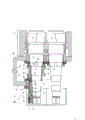
Fig. 1 represents the layout drawing of mill train,
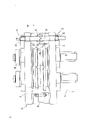
Fig. 2 represents the quick-speed jigs of an adjustment unit double base collars,
Fig. 3 represents the adjustment unit of layer structure roll clamping frame,
Fig. 4 represents the partial cross section figure by roll clamping frame shown in Figure 3.
Figure 1 shows that the high-efficiency small-sized ferrous rolling mill and the rod-rolling mill machine row of combined type continuous operation, it have by and be listed in and arrange the roughing train 1 that the arranged in order mill stand is formed by horizontal/vertical (H/V) frame on the rolling axis, and equally also the configuration mill stand forms by putting in order by horizontal/Vertical Rack side by side thereafter, the middle machine row 2 of a finishing mill line 3 of its heel.Finishing mill line is middle machine row in wire production.These finishing mill line 3 back be final processing section 4 be provided with detailed show mostly by a cooling device 5 that has pusher/form around the water-cooled section of volume device and stelmor (Stelmor) equipment.The back of finishing mill line 3 is a cooling bed or storage bed 6 when producing bar steel or section bar.A whole set of mill train abbreviates the CL frame as and forms mainly by so-called cantilever rolling mill frame, promptly has the suspend frame of collars of a side and forms.The characteristics of mill train are that particularly initial CL frame has interconvertible clamping frame unit in the roughing train, and promptly it can be replaced by the collars of two-side supporting.Whole transmissions, driving and the housing unit of the CL frame on the mill train (not detailed illustrating) all can be used for double base collars clamping frame.Collars with supporting like this provides the rolled piece possibility that rolling in high quality open rolling cross section is big and shaping resistance is high for the initial frame of roughing train just.Middle machine row 2 or can be on demand in finishing mill line 3 for section bar production dispose the adjustment unit 8 that several mill stands have a double base collars 10 ', 8 ".Because whole transmissions, driving and the housing unit of the CL frame of mill train also all can be utilized in middle machine row or finishing mill line, the adjustment unit that is used for section bar production must not belong to the original equipment of mill train, and can have when needed the CL adjustment unit of the collars that suspends and adjustment unit 8 that has double base collars 10 ', 8 " replace.
Fig. 2 represents the quick-speed jigs of the double base collars 10 of a corresponding adjustment unit in roughing train and middle machine row or the finishing mill line.Quick-speed jigs 11 is to be configured on the transmission clamping frame 12.First bearing 13, a multilayer plain bearing of the axle 14 of collars 10 preferably is positioned at eccentric bushing 15, and this eccentric bushing can rotate by a unshowned housing pin that has worm thread 16.Therefore the pass gap of collars is adjustable.Be equipped with collars 10,10 ' axle 14,14 ' by means of by the gear 17,17 of detailed preposition actuator drives of showing ' drive.Second bearing 18 of collars 10 is a multilayer plain bearing equally, it be installed in an eccentric bushing 15 ' in.One of second bearing 18 and eccentric bushing 15 ' be positioned at and transmission clamping frame 12 are by for example bolted cramp frame 19.Cramp frame 19 is made up of two camber members, but their engagement devices 20 by a quick-release link together.The eccentric bushing 15 and 15 of the clutch shaft bearing 13 and second bearing 18 ' be connected for known pressure is realized rotation synchronously to guarantee eccentric bushing by the housing pin of engagement in screw flight 16.
The tension of the quick-speed jigs 11 of collars 10 and assembling element comprise the detailed importing of showing and derive guide and guards-begun-be described as follows by the end of axle 14:
For dismounting collars 10, at first cramp frame 19 is separated the transmission clamping frame by engagement device 20.Be installed in centering unit on the transmission clamping frame by hydraulic clamp, make owing to clamping the centering bolt that is suppressed with compression spring to advance, then steady pin is screwed out (know clearly and illustrate) from the centering bolt with hand.
Now, the clamping piston 25 of collars is clamped more by hydraulic pressure, clamp nut 21 is loosened and is rotated.Clamping piston 25 is and then released, to tapered sleeve 27 loosen piston 26 by hydraulic clamp, therefore by cylinder barrel spare 24, splicing sleeve 28, the member unit that tapered sleeve 27 and collars 10 are formed is split out from axle 14.An independent provision for disengagement does not then need.Owing on cramp frame 19, also be fixed with the not detailed roll fittings that shows, so the center of gravity 9 that whole unit can be pressed it is by a lifting unit, for example be configured in transportation ring on the cramp frame 19 from frame migration assembly section by means of one, the collars 10 that suit is new there, fixing new guide and guards is also finished adjustment work.
For assembling new collars together with the new guide and guards of harmonizing, with combiner by means of crane or quick exchange apparatus is transported to mill stand 7 from the assembly section and cover installs on the roll mandrel 14.Assembling is carried out as follows: clamp nut 21 is to screwing the direction rotation, and combiner centrally is pulled on axle 14.The annular that is used to clamp the annular clamping piston 37 of tapered sleeve 27 and be used for tapered sleeve 27 is loosened piston 26 by hydraulic unlock.The clamping piston 25 that is used for collars now is clamped, thereby collars is pressed on the restraint face 30 of stop collar 32 by the bearing-surface 29 of splicing sleeve 28.
The annular piston 37 that is used to clamp tapered sleeve 27 is clamped and is pushed into by hydraulic pressure pwc.And then the clamping piston 25 of collars 10 with maximum pressure pre-clamp and with locking nut 22 hand-tight make-ups on backstop.
New roll and new roll fittings are by the eccentric bushing of forcing to be connected 15,15 ' adjust on the new pass gap.
Fig. 3 and Fig. 4 illustrate another have the interconvertible adjustment unit 8,8 of being arranged to layer structure roll clamping frame 40 ', 8 ".The roll clamping frame has at the clamping plate 44 of its end protrusion and mutual wedging fastener 45 by two and forms.Collars axle 41 is bearing in the bearing 42 in the clamping plate.The axle head of collars axle 41 can insert in the unshowned transmission clamping frame 47.At the visible hydraulic nut 50 of another axle head of collars axle 41, by means of a tapered sleeve 49 of shifting onto on the collars axle, collars 46 radially is fixed on the axle 41 by it.Dispose adjustment unit 43 in the outside of clamping plate 44 to adjust collars 46 each pass gap.Pinion 54 shown in Figure 3, as to rotate by the not shown handwheel that can shift onto on the axle 55 separately, by unshowned, the eccentric bushing 57(Fig. 4 that has at least another intermediate spur gear to act on to be provided with external tooth 56) on.The bearing unit of collars axle in eccentric bushing 57 disposes self aligning roller bearing in this example.Eccentric bushing 57 is connected with another adjustment unit 43 pressures on the clamping plate 44 that are installed in sensing transmission clamping frame 47 by jackshaft 55 at transmission side.Another only is shown for the sake of simplicity by the bearing unit 42 that self aligning roller bearing is formed among Fig. 4, it is identical with the eccentric bushing 57 shown on front plate 44 that the eccentric bushing of self aligning roller bearing 42 is housed.
Fig. 3 also shows, whole roll clamping frame 40 can be dismantled from transmission clamping frame 47 and be changed by a new clamping frame, changes with another clamping frame or another clamping frame with disalignment carpenters square cun in case of necessity.Fig. 3 also illustrates, and the front plate 44 of roll clamping frame 40 can be changed separately when needed, changes together with collars 46 and/or roll fittings in case of necessity.To loosen or dismantle for this reason the bolt of fastener 45, and hydraulic nut 50 decompressions are loosened.When the dismounting front plate, because collars 46 is enclosed within on the tapered sleeve 49, it also together is disassembled from the collars axle.Thereby collars 46 just can be near also directly changing a new collars from tapered sleeve 49 dismountings like this.If collars cooling device 48 is stayed on those clamping plate 44 that can be connected with transmission clamping frame 47 (Fig. 3) with other hydraulic joints, then keep in repair the roll clamping frame and will more can significantly reduce with replacing collars required time.The collars of the different-diameter of being changed in the drawings with 46 ' and 46 " mark.
Collars 46 is installed in one on the tapered sleeve of pushing open on the collars axle 41 49 as previously mentioned, and for the clamping of collars with loosen this tapered sleeve and radially be subjected to the axial pressure effect of hydraulic nut 50, its mode of action supposition is known.For making collars 46 not only radially, and axially and tangential direction be fixed on the collars axle 41, collars 46 is fixed between the annular clamping element 51, wherein embed friction plate 52 as connector, and clamping element 51 is with tapered sleeve 49 or mesh with keyway on the opposite side of collars axle 41 53 of clamping element 51 and collars sidewalls.
Above-mentioned embodiment shown in not only being confined to according to measures of the present invention equally also is applicable to this type of organization plan in all authority claimed range.
Claims (19)
1, the high-efficiency small-sized ferrous rolling mill of combined type continuous operation and rod-rolling mill machine row, the roughing train that respectively has a plurality of mill stands or roll unit, have in the middle of one machine row and the finishing mill line that is connected at least together with the final processing section that may be used for the back, it is characterized in that some mill stands (7) that mainly one-sided by having (hanging) puts mill train configuration in roughing train (1) and middle machine row (2) and/or finishing mill line (3) that the CL frame (7) of collars (10) forms have the adjustment unit (8 that collars (10) are supported in both sides (two), 8 ', 8 ").
2, by described light shape milling train of claim 1 and rod-rolling mill machine row, it is characterized in that, in some frames (7) of roughing train (1) and middle machine row (2) and/or finishing mill line (3), have the collars that suspends the CL adjustment unit can by an adjustment unit that has double base collars (10) (8,8 ', 8 ") replace.
3, by claim 1 or 2 described light shape milling trains and rod-rolling mill machine row, it is characterized in that (8 ") can be used for dividing before this bifilar finish rolling of rolling the circle material to the adjustment unit of band double base collars (10) in finishing mill line (3).
4, by described light shape milling train of claim 3 and rod-rolling mill machine row, it is characterized in that the collars of adjustment unit (10) is provided with one or two pass.
By claim 3 or 4 described light shape milling trains and rod-rolling mill machine row, it is characterized in that 5, a roll unit has horizontal/vertical (H/V) device of double base collars (10) adjustment unit.
6, by at least one described light shape milling train of item in the claim 1 to 5 and rod-rolling mill machine row, it is characterized in that a horizontal/vertical device of suspend between frame (7) collars and double base collars (10).
7, by at least one described light shape milling train of item in the claim 1 to 6 and rod-rolling mill machine row, it is characterized in that, the adjustment unit (8 8 ' 8 ') that has double base collars (10) has one to comprise second bearing (18) and be configured in cramp frame (19) on the transmission clamping frame (12) that comprises clutch shaft bearing (13), the camber member that it is connected by two available engagement devices that can separate fast (20) (19 ', 19 ") constitute.
8, described by one of aforementioned claim, particularly described light shape milling train of claim 7 and rod-rolling mill machine are listed as, it is characterized in that, can control automatically for one, the quick-speed jigs that is used for double base collars (10) (11) of hydraulic action preferably, these anchor clamps have a piston-cylinder tube unit (25 that acts on (10) end faces of collars (30) at least at least, 26) be used for this collars vertically clamping and loosen, and also have at least a piston-cylinder tube unit (37) that acts on the collars (10) be used for one that collars (10) is housed and can go up tapered sleeve (27) of moving configuration in radially clamping with loosen at its axle (14).
9, by at least one described light shape milling train of item in the aforementioned claim and rod-rolling mill machine row, it is characterized in that, tapered sleeve (27) is distolateral can be connected by means of piston-cylinder tube unit by upward mobile configuration, that (10) second bearings of collars (18) are housed splicing sleeve (28) at the axle (14) of collars (10) with one, and splicing sleeve (28) abuts against on the end face (30) of collars (10).
10, by at least one described light shape milling train of item in the aforementioned claim and rod-rolling mill machine row, it is characterized in that the other end (31) of collars (10) abuts against on the stop collar (32) of collars (10) axle (14).
11, by at least one described light shape milling train of item in the aforementioned claim and rod-rolling mill machine row, it is characterized in that, respectively be provided with a friction plate (28) between bearing-surface of splicing sleeve (28) (29,30) and the collars (10) and between the bearing-surface (33,31) of stop collar (32) and the collars (10).
12, by at least one described light shape milling train of item in the aforementioned claim and rod-rolling mill machine row, it is characterized in that, the other end (39) of splicing sleeve (28) is connected with a cylinder barrel spare (24), be used for the piston (25) that collars (10) clamps and be used for piston (26) that tapered sleeve (27) loosens be slide arrangement therein, piston (25,26) all is arranged to annular piston and is sleeved on the axle (14) that collars (10) are housed at this moment.
13, by at least one described light shape milling train of item in the aforementioned claim and rod-rolling mill machine row, it is characterized in that, cylinder barrel spare (24) connects same clamp nut (21) by the intermediate structure of a retainer ring (23) in case of necessity, a locking nut (22) particularly, direction at axle (14) can clamp facing to splicing sleeve (28) and tapered sleeve (27), for improving the clamping force on the axle (14), locking nut this moment (22) can be tightened by means of screw thread.
14, by at least one described light shape milling train of item in the aforementioned claim and rod-rolling mill machine row, it is characterized in that, stop collar (32), tapered sleeve (27) and splicing sleeve (28) are that shape is adaptive in tangential direction, preferably go up configuration wedge key (36) by means of vertical tooth (34,35) or at the axle (14) that collars (10) is housed.
15, by at least one described light shape milling train of item in the claim 1 to 6 and rod-rolling mill machine row, it is characterized in that, adjustment unit (8,8 ', 8 ") have an interchangeable roll clamping frame (40) and constitute with layer structure, mainly single collars axle (41) is housed at least by two and its bearing unit (42) is housed and the clamping plate (44) of adjustment unit (43) together with in its end bosses and the fastener (45) of mutual wedging is formed.
16, by described light shape milling train of claim 15 and rod-rolling mill machine row, it is characterized in that the front plate (44) of roll clamping frame (40) can be changed separately when needing, and changes together with collars (46) and/or roll fittings in case of necessity.
17, by claim 15 or 16 described light shape milling trains and rod-rolling mill machine row, it is characterized in that, on the clamping plate (44) that can be connected, be provided with collars cooling device (48) and other hydraulic joints with transmission clamping frame (47).
18, by claim 15,16 or 17 described light shape milling trains and rod-rolling mill machine row, it is characterized in that, collars (46) is enclosed within one on the tapered sleeve of pushing open on the collars axle (41) (49), for collars (46) radially clamping and loosen the effect that this tapered sleeve is subjected to a hydraulic nut (50) axial compressive force.
19, by at least one described light shape milling train of item in the claim 15 to 18 and rod-rolling mill machine row, it is characterized in that, collars (46) is fixed between the annular clamping element (51), clamping element is close on the side (53) with friction plate connector (52), and meshes with keyway with tapered sleeve (49) or collars axle (41).
Applications Claiming Priority (2)
| Application Number | Priority Date | Filing Date | Title |
|---|---|---|---|
| DE4014411 | 1990-05-04 | ||
| DEP4014411.9 | 1990-05-04 |
Publications (1)
| Publication Number | Publication Date |
|---|---|
| CN1056268A true CN1056268A (en) | 1991-11-20 |
Family
ID=6405745
Family Applications (1)
| Application Number | Title | Priority Date | Filing Date |
|---|---|---|---|
| CN91102780A Pending CN1056268A (en) | 1990-05-04 | 1991-05-04 | Combined small ferrous rolling mill and rod-rolling mill machine row |
Country Status (6)
| Country | Link |
|---|---|
| US (1) | US5144828A (en) |
| EP (1) | EP0455082B1 (en) |
| JP (1) | JP2810557B2 (en) |
| CN (1) | CN1056268A (en) |
| AT (1) | ATE107876T1 (en) |
| DE (1) | DE59102051D1 (en) |
Cited By (2)
| Publication number | Priority date | Publication date | Assignee | Title |
|---|---|---|---|---|
| CN107052044A (en) * | 2016-12-01 | 2017-08-18 | 成都金中机械设备制造有限公司 | The roller list eccentric bushing milling train of central driving cantilever two and adjusting method |
| CN117282765A (en) * | 2023-09-26 | 2023-12-26 | 安徽富凯特材有限公司 | Continuous rolling mill capable of circumferential deformation |
Families Citing this family (14)
| Publication number | Priority date | Publication date | Assignee | Title |
|---|---|---|---|---|
| US5307663A (en) * | 1993-01-12 | 1994-05-03 | Morgan Construction Company | Multiple outlet finishing mill |
| US5595083A (en) * | 1994-08-01 | 1997-01-21 | Morgan Construction Company | Modular rolling mill |
| IT1281447B1 (en) * | 1995-11-09 | 1998-02-18 | Danieli Off Mecc | LAMINATION RING LOCKING GROUP |
| US6053022A (en) * | 1998-09-14 | 2000-04-25 | Morgan Construction Company | Modular rolling mill |
| US6604859B1 (en) | 2002-01-23 | 2003-08-12 | Morgan Construction Company | Bushing for oil film bearing |
| ITUD20040057A1 (en) * | 2004-03-29 | 2004-06-29 | Pittini Impianti Srl | COLD ROLLING PLANT FOR WIRES AND |
| US7191629B1 (en) | 2006-04-13 | 2007-03-20 | Morgan Construction Company | Modular rolling mill |
| US7523632B2 (en) * | 2007-02-15 | 2009-04-28 | Morgan Construction Company | Modular rolling mill |
| CN101929014B (en) * | 2010-08-30 | 2011-12-07 | 苏州迪盛织造整理有限公司 | Connecting device of sectional warping machine and sizing machine |
| CN103691738A (en) * | 2013-12-20 | 2014-04-02 | 宣化钢铁集团有限责任公司 | Technology of 10 rack finishing mill group for producing anti-seismic reinforcing steel bar |
| CN106185465A (en) * | 2016-08-31 | 2016-12-07 | 漯河利通液压科技股份有限公司 | Supertension heavy caliber petroleum drilling delivery hose steel wire coiler tenslator |
| ES2774536T3 (en) * | 2017-03-22 | 2020-07-21 | Koellges Ralf | Hydraulic tensioning device for detachable friction drag connection of two components |
| CN109848208A (en) * | 2017-11-30 | 2019-06-07 | 浙江立新珠宝科技有限公司 | A kind of fully automatic loop rolling line mechanism |
| US11478831B2 (en) | 2020-03-04 | 2022-10-25 | Primetals Technologies USA LLC | Mechanical high speed roll change system for use with robotic roll change system |
Family Cites Families (18)
| Publication number | Priority date | Publication date | Assignee | Title |
|---|---|---|---|---|
| DE1232915B (en) * | 1957-11-16 | 1967-01-26 | Kocks Gmbh Friedrich | Rolling mill for the continuous rolling of fine iron |
| DE1243621B (en) * | 1961-02-06 | 1967-07-06 | Schloemann Ag | Rolling frame, in particular for rolling wire |
| AT256006B (en) * | 1961-11-25 | 1967-08-10 | Moossche Eisenwerke Ag | Process for rolling out profiles by means of caliber rollers |
| GB1119581A (en) * | 1965-02-04 | 1968-07-10 | Hille Engineering Company Ltd | An improvements in or relating to rolling mill apparatus |
| US3587277A (en) * | 1968-09-30 | 1971-06-28 | Pomini Farrel Spa | Continuous rolling mill |
| FR2048693A5 (en) * | 1969-05-27 | 1971-03-19 | Properzi Ilario | |
| JPS4949856A (en) * | 1972-05-26 | 1974-05-15 | ||
| US3945234A (en) * | 1975-01-02 | 1976-03-23 | Rolf Steinbock | Tandem rolling mill arrangement |
| US3995353A (en) * | 1975-12-10 | 1976-12-07 | Morgan Construction Company | Multi groove roll mounting means |
| JPS53132451A (en) * | 1977-04-26 | 1978-11-18 | Nippon Kokan Kk <Nkk> | Rolling mill |
| AT370643B (en) * | 1981-05-14 | 1983-04-25 | Gfm Fertigungstechnik | ROLLING MILLS |
| US4423612A (en) * | 1981-12-18 | 1984-01-03 | Southwire Company | Cantilevered roll shaft bearing bracket |
| IT1175058B (en) * | 1983-02-25 | 1987-07-01 | Danieli Off Mecc | SUPER-COMPACT LAMINATION BLOCK WITH ROLLER ROLLERS AND LAMINATION LINE INCLUDING BLOCKS SO FORMED |
| DE3316289A1 (en) * | 1983-05-04 | 1984-11-08 | Uwe 2104 Hamburg Kark | COMPOSITE ROLLER WITH A MEANS OF A CONE SLEEVE ON THE ROLL RING HOLDED |
| JPS6049804A (en) * | 1983-08-30 | 1985-03-19 | Kobe Steel Ltd | Roll mounting device of cantilever mill |
| EP0163104B1 (en) * | 1984-04-28 | 1989-11-29 | Sms Schloemann-Siemag Aktiengesellschaft | Roll stand |
| AT390572B (en) * | 1988-05-13 | 1990-05-25 | Voest Alpine Ind Anlagen | DEVICE FOR FASTENING A ROLL RING ON A ROLL SHAFT |
| DE3834606A1 (en) * | 1988-10-11 | 1990-04-12 | Voest Alpine Ind Anlagen | Device for fixing a roll ring |
-
1991
- 1991-04-20 AT AT91106401T patent/ATE107876T1/en active
- 1991-04-20 DE DE59102051T patent/DE59102051D1/en not_active Expired - Fee Related
- 1991-04-20 EP EP91106401A patent/EP0455082B1/en not_active Expired - Lifetime
- 1991-05-01 JP JP3099995A patent/JP2810557B2/en not_active Expired - Fee Related
- 1991-05-04 CN CN91102780A patent/CN1056268A/en active Pending
- 1991-05-06 US US07/696,190 patent/US5144828A/en not_active Expired - Lifetime
Cited By (3)
| Publication number | Priority date | Publication date | Assignee | Title |
|---|---|---|---|---|
| CN107052044A (en) * | 2016-12-01 | 2017-08-18 | 成都金中机械设备制造有限公司 | The roller list eccentric bushing milling train of central driving cantilever two and adjusting method |
| CN107052044B (en) * | 2016-12-01 | 2019-02-05 | 成都金中机械设备制造有限公司 | Two roller list eccentric bushing milling train of central driving cantilever and adjusting method |
| CN117282765A (en) * | 2023-09-26 | 2023-12-26 | 安徽富凯特材有限公司 | Continuous rolling mill capable of circumferential deformation |
Also Published As
| Publication number | Publication date |
|---|---|
| JPH04228205A (en) | 1992-08-18 |
| ATE107876T1 (en) | 1994-07-15 |
| EP0455082B1 (en) | 1994-06-29 |
| EP0455082A1 (en) | 1991-11-06 |
| US5144828A (en) | 1992-09-08 |
| JP2810557B2 (en) | 1998-10-15 |
| DE59102051D1 (en) | 1994-08-04 |
Similar Documents
| Publication | Publication Date | Title |
|---|---|---|
| CN1056268A (en) | Combined small ferrous rolling mill and rod-rolling mill machine row | |
| CN101574705B (en) | Two transmission shaft and four roller cross adjustable universal rolling mill and universal continuous rolling mill set formed by same | |
| EP0346880B1 (en) | Adjustable width rolls for rolling mill | |
| CA2627586C (en) | Elimination of rolling mill chatter | |
| US4305678A (en) | Coupling for a mill roll | |
| DE19816602C1 (en) | Roller frame for roll forming materials | |
| EP0560093B1 (en) | Small section-/wire rod mill | |
| EP1019204A1 (en) | Rolling mill stand | |
| JPH01313101A (en) | Working method and roll train for continuously rolling molded continuous rolling material into production cross-sectional shape having accurate dimension | |
| US4182149A (en) | Roll stand | |
| CN201214103Y (en) | Double transmission shaft four roll cross adjustable universal rolling mill and universal continuous rolling mills constituted thereby | |
| US4993251A (en) | Rollstand having easily replaceable roll dies | |
| CN111375635B (en) | Automatic disassembling tool for roller bearing and using method thereof | |
| US4976127A (en) | Double roller crossrolling mill for piercing and stretching of solid and hollow blocks | |
| US2688891A (en) | Rolling mill | |
| US7024906B2 (en) | Roll stand for rolling bar-shaped or tubular material | |
| US4287745A (en) | Rolling mill screwdown | |
| SU1724400A1 (en) | Rolling mill | |
| CN1050542C (en) | A roll-pair drive arrangement | |
| US2002531A (en) | Rolling mill | |
| JPH0433709A (en) | Rolling roll of variable width | |
| EP0501600B1 (en) | Rolling stand | |
| CN2366193Y (en) | Integral bearing type high stiffness rolling mill | |
| US3323344A (en) | Roll forging machine | |
| JP2545947B2 (en) | Centering method for multi-stage steel pipe rolling machine |
Legal Events
| Date | Code | Title | Description |
|---|---|---|---|
| C06 | Publication | ||
| PB01 | Publication | ||
| C10 | Entry into substantive examination | ||
| SE01 | Entry into force of request for substantive examination | ||
| C01 | Deemed withdrawal of patent application (patent law 1993) | ||
| WD01 | Invention patent application deemed withdrawn after publication |