CN1052953A - Coherent radar - Google Patents
Coherent radar Download PDFInfo
- Publication number
- CN1052953A CN1052953A CN89102320.8A CN89102320A CN1052953A CN 1052953 A CN1052953 A CN 1052953A CN 89102320 A CN89102320 A CN 89102320A CN 1052953 A CN1052953 A CN 1052953A
- Authority
- CN
- China
- Prior art keywords
- frequency
- magnetron
- signal
- pulse
- oscillator
- Prior art date
- Legal status (The legal status is an assumption and is not a legal conclusion. Google has not performed a legal analysis and makes no representation as to the accuracy of the status listed.)
- Pending
Links
- 230000001427 coherent effect Effects 0.000 title claims abstract description 12
- 230000005540 biological transmission Effects 0.000 claims abstract description 15
- 238000011105 stabilization Methods 0.000 claims abstract description 8
- 238000006243 chemical reaction Methods 0.000 claims description 8
- 238000000034 method Methods 0.000 claims description 8
- 230000006641 stabilisation Effects 0.000 claims description 7
- 230000010355 oscillation Effects 0.000 abstract description 10
- 230000001960 triggered effect Effects 0.000 abstract description 5
- 239000000203 mixture Substances 0.000 description 4
- 238000002347 injection Methods 0.000 description 3
- 239000007924 injection Substances 0.000 description 3
- 239000004020 conductor Substances 0.000 description 2
- 238000010586 diagram Methods 0.000 description 2
- 238000001914 filtration Methods 0.000 description 2
- 230000009466 transformation Effects 0.000 description 2
- 230000003321 amplification Effects 0.000 description 1
- 238000013459 approach Methods 0.000 description 1
- 230000008859 change Effects 0.000 description 1
- SOPYTFSYTUAGFR-OEAKJJBVSA-N chembl2431390 Chemical compound C1=CC=C2C(/C=N/NC(=O)CCN3C4=CC=CC=C4N=C3C)=C(O)C=CC2=C1 SOPYTFSYTUAGFR-OEAKJJBVSA-N 0.000 description 1
- 230000005284 excitation Effects 0.000 description 1
- 230000007246 mechanism Effects 0.000 description 1
- 238000003199 nucleic acid amplification method Methods 0.000 description 1
- 230000008569 process Effects 0.000 description 1
- 239000000243 solution Substances 0.000 description 1
- 125000006850 spacer group Chemical group 0.000 description 1
- 230000007704 transition Effects 0.000 description 1
- 230000003245 working effect Effects 0.000 description 1
Images

Classifications
-
- G—PHYSICS
- G01—MEASURING; TESTING
- G01S—RADIO DIRECTION-FINDING; RADIO NAVIGATION; DETERMINING DISTANCE OR VELOCITY BY USE OF RADIO WAVES; LOCATING OR PRESENCE-DETECTING BY USE OF THE REFLECTION OR RERADIATION OF RADIO WAVES; ANALOGOUS ARRANGEMENTS USING OTHER WAVES
- G01S7/00—Details of systems according to groups G01S13/00, G01S15/00, G01S17/00
- G01S7/02—Details of systems according to groups G01S13/00, G01S15/00, G01S17/00 of systems according to group G01S13/00
- G01S7/28—Details of pulse systems
- G01S7/285—Receivers
- G01S7/288—Coherent receivers
-
- G—PHYSICS
- G01—MEASURING; TESTING
- G01S—RADIO DIRECTION-FINDING; RADIO NAVIGATION; DETERMINING DISTANCE OR VELOCITY BY USE OF RADIO WAVES; LOCATING OR PRESENCE-DETECTING BY USE OF THE REFLECTION OR RERADIATION OF RADIO WAVES; ANALOGOUS ARRANGEMENTS USING OTHER WAVES
- G01S7/00—Details of systems according to groups G01S13/00, G01S15/00, G01S17/00
- G01S7/02—Details of systems according to groups G01S13/00, G01S15/00, G01S17/00 of systems according to group G01S13/00
- G01S7/28—Details of pulse systems
- G01S7/282—Transmitters
Abstract
Coherent radar comprises magnetron, modulator, local oscillator, frequency mixer, intermediate-frequency oscillator and phase-sensitive detector (PSD).According to the present invention, the vibration of magnetron is locked in extraneous signal in two steps.It is achieved in that before magnetron triggered, the signal of the local oscillator of self-stabilization was delivered to its tuning cavity in the future.Magnetron when not reaching its final amplitude in magnetron starting of oscillation, interrupts described signal to present after triggering immediately, replaces the signal that will have the magnetron transmission frequency and is added to tuning cavity.So the vibration of magnetron is locked in the signal that is produced by stable oscillation device.
Description
The present invention relates to coherent radar, described radar comprises: (1) magnetron; (2) modulator drives magnetron with it and produces and send high-frequency impulse; (3) stalo, produce intermediate-freuqncy signal with it, that is, by this local oscillator frequency with produce frequency by the echo-pulse mixing that transponder pulse causes and produce the intermediate-freuqncy signal of frequency corresponding to the difference of described local oscillator frequency and transponder pulse frequency corresponding to the echo-pulse mixing that described local oscillator frequency and transponder pulse cause; And (4) work in the oscillator of intermediate frequency.The intermediate-freuqncy signal of the output signal of described intermediate-frequency oscillator after described mixing delivered to phase-sensitive detector (PSD), so that detect echo-pulse and produce so-called bipolar video signal, it especially comprises the information of mutual phase relation between the high-frequency signal of launching and receiving.After Filtering Processing, the bipolar video signal can be used for (not only in the monodrome distance interior but also in non-monodrome distance) and separately has the target with respect to the different radial velocities of radar station, for example, be used to suppress the echo that comes from fixed target, so that show events target only.
When magnetron during as the high frequency source in this quasi-coherent radar, importantly: can make it produce a kind of like this vibration, that is, this vibration have with respect to from the signal of intermediate-frequency oscillator and from the mixing composition of the signal of stalo, the fixed phase relationship of pulse one by one.
Formerly propose, promptly, in the ways of addressing this issue of describing in Swedish patent SE8400140-3 number, in such a way modulator and intermediate-frequency oscillator are carried out mutual timing controlled, promptly, the modulator pulses forward position, thereby the magnetron pulse forward position always appears at the predetermined phase position of intermediate-frequency oscillator output signal, in addition, before triggering magnetron, at a time in the interbody spacer, suitably deriving from the tuning cavity of delivering to magnetron in the signal of the phase stabilization of the stalo that has existed, that is, so-called " igniting ".This igniting means, when triggering magnetron and beginning to set up self-sustained oscillation, has had given oscillation energy in magnetron cavity.This phase place that causes vibrating will be locked in the ignition signal that derives from the stable oscillator of continuous working.So just obtain the phase continuity of the pulse one by one of magnetron vibration.
Shortcoming according to the solution of Swedish patent 8400140-3 number is: the duration of whole magnetron pulse, the magnetron vibration is not phase-locked, and the duration of pulse itself, described phase place easily produces drift.Although when short pulse uses, moving-target indication (MTI) performance can be fairly good, especially when prolonging magnetron pulse, will cause the MTI performance bad.
Purpose of the present invention will be improved as opening TOUYIJIE described exactly, the coherent radar that has the type of IGNITION CONTROL like that 8400140-3 number according to Swedish patent, make that this radar all has MTI performance preferably no matter be used for the still long radar pulse of short radar pulse.
According to the present invention, realize above-mentioned purpose by the following method, promptly, this radar comprises the device that is used for changing the frequency of described phase stabilization signal between the magnetron pulse front porch interval, and described frequency shift makes that the final frequency (also keeping this terminal point frequency duration of magnetron pulse) of pulse front edge end is consistent with the transmission frequency of magnetron.
The most handy reversing arrangement of variation of frequency, with the mode proceed step by step at least one step, this is just controlled the simple mechanism of (for example controlling by the time) easily.
The present invention relates to carry out being same as extraneous signal phase-locked of magnetron transmission frequency with respect to its frequency with at least two kinds of working methods.The first step is the previous IGNITION CONTROL that proposes, and this step is just interrupted when magnetron has started but also do not reached final amplitude, that is, continue the duration of pulse front edge.Then, in last working method, the phase-locked accurately of the signal identical with the magnetron transmission frequency occur, the duration of magnetron pulse, keep this lockin signal with respect to frequency.Because ignition signal and lockin signal all result from the stable oscillator of continuous working, so the mutual phase relation between ignition signal and the lockin signal is also with constant, the pulse of magnetic tubulation will have the phase continuity from the pulse to the pulse.
Owing to carry out phase-locked with at least two kinds of working methods, so, during the whole pulse persistance of magnetron (that is end) from the starting point of pulse to the magnetron pulse non-neutralizable fraction, with compare from the phase-locked situation of single working method, the phase place of magnetron vibration will be more constant.
Should be noted that the process that magnetron is locked in the extraneous signal with frequency identical with the magnetron transmission frequency is known.In this case, the work of magnetron more resembles amplifier and does not resemble self-excited oscillator; Effectively phase-locked in order to obtain, must be injected into magnetron to the quantity of power of considerable outer lock phase signals.In addition, after magnetron pulse begins and before the phase stabilization of the vibration that is produced, need the regular hour.At this moment, to long magnetron pulse, its MTI performance can be relatively good, and to short pulse, its MTI performance is with bad.
If the conversion of two signals by having different frequency in one step changes realizes that frequency change (wherein, first signal with first frequency was fed to magnetron before the magnetron excitation, and the secondary signal of second frequency with the final frequency of equaling is before magnetron vibration reaches its whole range, between the magnetron pulse front porch interval, be transported to magnetron), so, when according to most preferred embodiment of the present invention, the oscillator that above-mentioned two kinds of frequencies all result from existing phase stabilization (promptly, stalo and intermediate-frequency oscillator) time, the simplest device just obtained.
Suitable method is: the signal with second frequency or final frequency can be produced by frequency mixer, in described frequency mixer, and the output signal mixing of the output signal of local oscillator and intermediate-frequency oscillator; Signal with first frequency is then produced by the output signal from local oscillator self.Therefore, the duration of the magnetron pulse forward position, be injected into the intermediate frequency that difference between two frequencies of magnetron tuning cavity will equal system.
In another embodiment, the signal of first frequency also can result from frequency mixer.In described frequency mixer, derive from the signal of local oscillator and derive from intermediate-frequency oscillator by conversion stage, for example signal mixing of frequency divider.Therefore, the difference that is injected into two frequencies of magnetron tuning cavity between the magnetron pulse front porch interval will depart from intermediate frequency.
If the control device by modulator or modulator is carried out control, just can obtain conversion equipment simply and is accurately controlled, if necessary, can also pass through chronotron, so that triggering moment of the starting of conversion equipment and magnetron will have given time relationship.
To and the present invention be described with reference to the accompanying drawings by means of embodiment below, in the accompanying drawings:
Fig. 1 illustrate according to of the present invention be the calcspar of the radar of high frequency source with the magnetron,
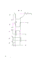
Fig. 2 illustrates and explains time diagram of the present invention, and
Fig. 3 illustrates the second embodiment of the present invention.
According to Fig. 1, from the short potential pulse driving magnetron MAG of modulator MOD, then, the high frequency HF pulse that is produced arrives by circulator CIRC and transmit-receive switch TR and is used for exomonental antenna ANT.Echo-pulse by the reflectance target that causes of radar pulse of emission is received by same antenna ANT, then, and via transmit-receive switch TR arrival frequency mixer B
1, there with from the combination of the output signal of stalo STALO.For example, by means of mechanical locking or step motor magnetron is adjusted to fixing transmission frequency.The transmission frequency f of magnetron
MAGWith the stalo frequency f
STALODifference be selected nominal IF-FRE f
MFOSo, from frequency mixer B
1Acquisition has described nominal value f
MFOIntermediate frequency f
MEEcho-pulse.Described intermediate-freuqncy signal arrives phase-sensitive detector (PSD) D again by intermediate frequency amplifier MF amplification, and the latter also receives the output signal from the oscillator MFO of continuous working.The frequency of operation of described oscillator is selected nominal intermediate frequency f
MFO, then, obtain to be called the V of bipolar video signal from phase-sensitive detector (PSD) D
BipSo it is called bipolarity is because it both can present on the occasion of also presenting negative value.The bipolar video signal except the intensity of expression echoed signal, the mutual phase position between the HF signal of expression emission and reception also.If the distance between radar equipment and the reflectance target becomes in time, bipolar video signal V then
BipTo become with frequency according to variable in distance, in other words, for the variable in distance of the every half-wavelength from the transmitter to the reflectance target, described bipolar signal will be covered one 360 ° sequence.Then, described bipolar signal is subjected to Filtering Processing at for example mti filter (on this wave filter principle is Hi-pass filter), so that suppress from fixed echo, perhaps separates apart from carrying out speed under the situation in non-monodrome.
In order to guarantee bipolar video signal V
BipCan represent effectively to launch and received signal between mutual phase relation, adopt following steps:
At first, magnetron oscillator is locked in the stable signal that is produced by two stable oscillator STALO and MFO, the output signal that this locking signal more approaches above-mentioned two oscillators is fed to frequency mixer B
2The signal that is obtained.From frequency mixer B
2This signal via the break-make type first converter SW
1, the second converter SW
2(may also have amplifier AMP) and circulator CIRC are fed to the tuning cavity of magnetron.Described converter SW
2Be controlled by the control module PRF of modulator MOD, its mode is: it is opened a way usually, but the moment closure before magnetron is triggered just in time, and, during the pulse persistance of whole magnetron, remain closed.Phase locking is carried out with two steps, before the triggering magnetron and during the first of magnetron pulse ascent stage, is not described from frequency mixer B therefore
2Output signal but be fed to the tuning cavity of magnetron from the output signal of stalo STALO.The conversion of described two kinds of signals is by means of converter SW
1Realize that when position 1, the output signal of this switch self-oscillation in the future device STALO is sent to the tuning cavity of magnetron, and when the second place 0, this switch is self-mixing device B in the future
2Output signal be sent to described resonator cavity.Converter SW
1Control module PRF by modulator controls (also may via chronotron DEL), its mode is: before triggering magnetron, place it in primary importance, and when magnetron starting of oscillation but when also not arriving the final value amplitude, promptly, between the magnetron pulse front porch interval, be placed on the second place 0.
Secondly, via control device PRF modulator MOD is carried out time control by intermediate-freuqncy signal oscillator MFO, its mode is: the magnetron pulse forward position always coincides with the given phase position of intermediate-frequency oscillator MFO output signal (for example, changing at zero of assigned direction).
Produce among the embodiment of pulse repetition rate prf in inside, described control device PRF can comprise counter, and it is used for writing down zero number of transitions of the plus or minus of intermediate-frequency oscillator output signal, and, make each the n time zero described modulator of transformation startup.The other practice is, can be by leading to the control conductor EXT of control device PRF
PrfCome to produce pulse repetition rate, as dotting among Fig. 1 from the outside.In this case, control device PRF can comprise AND gate, and it passes through control conductor EXT at one of its input end
PrfReception is from the signal of outside prf generator.At second input end, describedly can receive the pulse that the expression zero in the output signal of intermediate-frequency oscillator changes with door.So after receiving the prf signal from external generator, modulator (thereby magnetron) will be activated in first zero transformation place of assigned direction.
Described function is: in the last period in the back to back time interval of triggering magnetron, the sub-fraction of the output signal of stalo STALO is fed to the resonator cavity of magnetron.So, when magnetron is triggered, in magnetron cavity, have a spot of energy with frequency of stabilized oscillator.According to noted earlier, this frequency can be write as:
f
STALO=f
MAG-f
MFO
In the formula, f
MAGBe the transmission frequency of magnetron, f
STALOAnd f
MFOIt is the frequency of two stable oscillator STALO and MFO.
Because described oscillation energy derives from the continuous working stable oscillator, so it has the phase continuity from the pulse to the pulse; The self-oscillatory phase place that described oscillation energy influence is set up in this pipe when triggering magnetron.When the amplitude of vibration reach certain value, but have described oscillation frequency f when also little
STALOThe transmission of energy just interrupt, and replace from frequency mixer B
2The mixing composition be fed to magnetron cavity.From frequency mixer B
2One of mixing composition be:
f
STALO+f
MFO=f
MAG
Be locked in now and had frequency f by the phased magnetron vibration of external signal
MAGSignal.Frequency f
MAGThe mixing composition also have phase continuity from the pulse to the pulse because it derives from the stable oscillator of two continuous workings.Obviously, during whole magnetron pulse, when dividing two steps phase-locked, phase place is more stable when comparing only with a step.
By means of time diagram described function is described among Fig. 2, wherein, a) expression is from the voltage V of modulator
C, it represents the cathode voltage as the function of time t simultaneously, b) expression is as the cathode current I of the function of time
C, c) expression HF voltage (being the magnetron pulse that is produced) V
HFEnvelope, d) expression is fed to converter SW
2Gating pulse V
2, and e) expression is fed to converter SW
1Gating pulse V
1In Fig. 2 d, level 0 expression converter SW
2Be in position 0, promptly open a way, and the described converter of level 1 expression is in 1, promptly closed.In Fig. 2 e, level 0 expression converter SW
1Place position 0, at this moment, frequency mixer B
2Output signal inject the resonator cavity of magnetron, and level 1 expression converter SW
1Place position 1, at this moment, the output signal of local oscillator STALO is injected magnetron.
At t
1Moment, the potential pulse V that delivers to magnetron cathode that beginning is provided by modulator MOD
C, cathode voltage rises to very soon near its final value then.At time interval t
1To t
2In, the charging of magnetic control internal capacity.At t
2Moment (after this moment, and then cathode voltage arrives its final value), magnetron begins to produce the higher-order of oscillation.In the embodiment that provides, be positioned at t
1Moment the front t
0Moment, two converter SW
2And SW
1All place position 1.This means, in the described time interval before triggering magnetron, be fed to magnetron cavity from the output signal of local oscillator STALO.At t
3Moment, converter SW
1Get back to position 0, this means, local oscillator is ended to transmit output signal to magnetron cavity, and replaces frequency mixer B
2Output signal be fed to magnetron.t
3Moment must appear at the t that magnetron starts
2After moment.And, t
3Moment should appear at the t that the higher-order of oscillation reaches its last amplitude
4Before moment.In the embodiment that provides, t
3Moment is very near t
2Moment, this helps by with frequency mixer B
2Output signal inject magnetron cavity and carry out phase-locked.t
0Moment must appear at t
2Before moment, and, must be for example earlier than t
1Moment.At t
5Moment, converter SW
2Reset to position 0, thereby, the injection of lockin signal interrupted.t
5Moment appears at after magnetron pulse interrupted, this means the injection of keeping lockin signal during whole magnetron pulse.
Fig. 3 illustrates circuit embodiment, and in this embodiment, transmission frequency is different with the intermediate frequency in the system with the difference of the frequency that is sent to magnetron when magnetron starts.
In the mode same with first embodiment, by from the output signal of stable oscillator STALO and from the output signal of intermediate-frequency oscillator MFO at frequency mixer B
2The signal that middle mixing obtains to have transmission frequency.Oscillator STALO is tuned in the transmission frequency of magnetron and the difference of intermediate-frequency oscillator MFO frequency, therefore, and from B
2Mixing results have the transmission frequency of magnetron, this mixing results is at converter SW
1Inject magnetron when being in position 0.This was right after before magnetron pulse reaches its final amplitude and takes place.In embodiment, be from frequency mixer B starting the signal that moment delivers to magnetron according to Fig. 3
3Obtain, in described frequency mixer, from frequency mixer B
2The signal that comes with from oscillator MFO via frequency divider F
DivThe signal mixing that attracts with appropriate frequency.In the embodiment shown, from frequency divider F
DivThe output signal of coming also is used to control control module PRF.For the normal operation of system, after modulator MOD is triggered, the signal that comes from oscillator MFO with from frequency divider F
DivThe phase difference between signals of coming all must equate for all pulses.If at frequency divider F
DivIn cut apart with integer, then available simple mode is guaranteed this point, but other splitting factor also allows.But modulator can not be from frequency divider F
DivOutput signal in arbitrarily selected zero changing moment be triggered.
Except by means of the converter SW that controls by time variable from the signal of modulator (the perhaps control module of this modulator)
2Outward, also can be at the parameter of measuring magnetron, as cathode voltage, start converter SW comes up on the basis of cathode current or high-frequency envelope
2Also can the duration of the magnetron pulse forward position, use way to realize phase-locked more than two steps or frequency sweep.The transmission frequency of magnetron can depart from the final frequency of the lockin signal of injection a little, as long as this departing from remains in the what is called locking bandwidth relevant with injected frequency.The deviation that allows between injected frequency and magnetron self frequency is generally less than 1%.
Claims (7)
1, coherent radar comprises:
(1) control tube,
(2) modulator, it is used to drive magnetron and produces and send high-frequency impulse,
(3) stalo, it is used to produce intermediate-freuqncy signal, that is, the mixing of the echo-pulse that causes by described oscillator output signal with by transponder pulse produces the signal of frequency corresponding to the difference frequency between described local oscillator frequency and the transponder pulse frequency, and
(4) work in the oscillator of intermediate frequency,
The output signal of described intermediate-frequency oscillator is delivered to phase-sensitive detector (PSD) with the intermediate-freuqncy signal that obtains by described mixing and is detected echo-pulse, and generation especially comprises the signal of mutual phase location between the high-frequency signal of launching and receiving, as follows modulator and intermediate-frequency oscillator are carried out mutual timing controlled, promptly, the modulator pulses forward position, thereby the magnetron pulse forward position always appears at the predetermined phase position of intermediate-frequency oscillator output signal, simultaneously, the signal of phase stabilization is before triggering magnetron in certain time interval and during the magnetron pulse ascent stage, promptly, the duration of the magnetron pulse forward position, be fed to the magnetron tuning cavity, it is characterized in that also comprising:
Be used for the duration of the magnetron pulse forward position, changing the device of frequency of the signal of described phase stabilization, described frequency shift makes final frequency at the end of pulse front edge, and the transmission frequency with magnetron is consistent substantially, also keeps this final frequency during whole pulse persistance.
2, coherent radar as claimed in claim 1 is characterized in that:
By the starting conversion equipment, with the described frequency shift of mode proceed step by step at least one step.
3, coherent radar as claimed in claim 2, with a step by having under the situation that the method for changing between the signal of different frequency realizes described frequency shift at two, before triggering, magnetron adds first signal with first frequency, and between the magnetron pulse front porch interval, magnetron vibration adds the signal with second frequency or final frequency before reaching crest amplitude, it is characterized in that:
Described two kinds of frequencies all result from the oscillator of the phase stabilization that has existed, promptly described stalo and intermediate-frequency oscillator.
4, coherent radar as claimed in claim 3 is characterized in that:
Signal with second frequency or final frequency is produced the output signal of described local oscillator and the mixing in described frequency mixer of the output signal of described intermediate-frequency oscillator by mixing.
5, as the coherent radar of claim 3 or 4, it is characterized in that:
Signal with first frequency is the output signal from described local oscillator self, thereby, delivering to the frequency that difference frequency between two frequencies of magnetron tuning cavity equals intermediate-freuqncy signal between the magnetron pulse front porch interval.
6, as the coherent radar of claim 3 or 4, it is characterized in that:
Signal with first frequency results from frequency mixer, the signal that derives from local oscillator with derive from intermediate-frequency oscillator, via signal mixing in described frequency mixer of a conversion stage (for example frequency divider), thereby, delivering to the frequency that difference frequency between two frequencies of magnetron tuning cavity will depart from intermediate-freuqncy signal between the magnetron pulse front porch interval.
7, as each coherent radar among the claim 2-6, it is characterized in that:
Described conversion equipment is controlled by the control device of modulator or modulator, in case of necessity can be via chronotron, so that its starting will have the given time relationship with respect to triggering moment of magnetron.
Applications Claiming Priority (2)
| Application Number | Priority Date | Filing Date | Title |
|---|---|---|---|
| SE8801385A SE460805B (en) | 1988-04-14 | 1988-04-14 | COHERENT RADAR |
| SE8801385.9 | 1988-04-14 |
Publications (1)
| Publication Number | Publication Date |
|---|---|
| CN1052953A true CN1052953A (en) | 1991-07-10 |
Family
ID=20372012
Family Applications (1)
| Application Number | Title | Priority Date | Filing Date |
|---|---|---|---|
| CN89102320.8A Pending CN1052953A (en) | 1988-04-14 | 1989-04-11 | Coherent radar |
Country Status (5)
| Country | Link |
|---|---|
| US (1) | US4935744A (en) |
| EP (1) | EP0337567B1 (en) |
| CN (1) | CN1052953A (en) |
| DE (1) | DE68910862D1 (en) |
| SE (1) | SE460805B (en) |
Cited By (2)
| Publication number | Priority date | Publication date | Assignee | Title |
|---|---|---|---|---|
| RU2710363C1 (en) * | 2019-07-10 | 2019-12-26 | Акционерное общество "Центральный научно-исследовательский радиотехнический институт имени академика А.И. Берга" | Onboard detector with compensation for variations of magnetic fields |
| CN111913154A (en) * | 2020-08-14 | 2020-11-10 | 成都亘波雷达科技有限公司 | Magnetron radar receiving phase parameter word processing method |
Families Citing this family (41)
| Publication number | Priority date | Publication date | Assignee | Title |
|---|---|---|---|---|
| GB2444299B (en) * | 2006-11-30 | 2011-07-27 | Secr Defence | Weather radar signal processing |
| US8118447B2 (en) | 2007-12-20 | 2012-02-21 | Altair Engineering, Inc. | LED lighting apparatus with swivel connection |
| US7712918B2 (en) | 2007-12-21 | 2010-05-11 | Altair Engineering , Inc. | Light distribution using a light emitting diode assembly |
| US8360599B2 (en) | 2008-05-23 | 2013-01-29 | Ilumisys, Inc. | Electric shock resistant L.E.D. based light |
| US7976196B2 (en) | 2008-07-09 | 2011-07-12 | Altair Engineering, Inc. | Method of forming LED-based light and resulting LED-based light |
| US7946729B2 (en) | 2008-07-31 | 2011-05-24 | Altair Engineering, Inc. | Fluorescent tube replacement having longitudinally oriented LEDs |
| US8674626B2 (en) | 2008-09-02 | 2014-03-18 | Ilumisys, Inc. | LED lamp failure alerting system |
| US8256924B2 (en) | 2008-09-15 | 2012-09-04 | Ilumisys, Inc. | LED-based light having rapidly oscillating LEDs |
| US8444292B2 (en) | 2008-10-24 | 2013-05-21 | Ilumisys, Inc. | End cap substitute for LED-based tube replacement light |
| US8214084B2 (en) | 2008-10-24 | 2012-07-03 | Ilumisys, Inc. | Integration of LED lighting with building controls |
| US8653984B2 (en) | 2008-10-24 | 2014-02-18 | Ilumisys, Inc. | Integration of LED lighting control with emergency notification systems |
| US8901823B2 (en) | 2008-10-24 | 2014-12-02 | Ilumisys, Inc. | Light and light sensor |
| US7938562B2 (en) | 2008-10-24 | 2011-05-10 | Altair Engineering, Inc. | Lighting including integral communication apparatus |
| US8324817B2 (en) | 2008-10-24 | 2012-12-04 | Ilumisys, Inc. | Light and light sensor |
| US8556452B2 (en) | 2009-01-15 | 2013-10-15 | Ilumisys, Inc. | LED lens |
| US8362710B2 (en) | 2009-01-21 | 2013-01-29 | Ilumisys, Inc. | Direct AC-to-DC converter for passive component minimization and universal operation of LED arrays |
| US8664880B2 (en) | 2009-01-21 | 2014-03-04 | Ilumisys, Inc. | Ballast/line detection circuit for fluorescent replacement lamps |
| US8330381B2 (en) | 2009-05-14 | 2012-12-11 | Ilumisys, Inc. | Electronic circuit for DC conversion of fluorescent lighting ballast |
| US8299695B2 (en) | 2009-06-02 | 2012-10-30 | Ilumisys, Inc. | Screw-in LED bulb comprising a base having outwardly projecting nodes |
| WO2011005579A2 (en) | 2009-06-23 | 2011-01-13 | Altair Engineering, Inc. | Illumination device including leds and a switching power control system |
| CA2794512A1 (en) | 2010-03-26 | 2011-09-29 | David L. Simon | Led light tube with dual sided light distribution |
| CA2792940A1 (en) | 2010-03-26 | 2011-09-19 | Ilumisys, Inc. | Led light with thermoelectric generator |
| US8540401B2 (en) | 2010-03-26 | 2013-09-24 | Ilumisys, Inc. | LED bulb with internal heat dissipating structures |
| US8454193B2 (en) | 2010-07-08 | 2013-06-04 | Ilumisys, Inc. | Independent modules for LED fluorescent light tube replacement |
| JP2013531350A (en) | 2010-07-12 | 2013-08-01 | イルミシス,インコーポレイテッド | Circuit board mount for LED arc tube |
| US8523394B2 (en) | 2010-10-29 | 2013-09-03 | Ilumisys, Inc. | Mechanisms for reducing risk of shock during installation of light tube |
| US8870415B2 (en) | 2010-12-09 | 2014-10-28 | Ilumisys, Inc. | LED fluorescent tube replacement light with reduced shock hazard |
| CN102540262B (en) * | 2010-12-27 | 2013-10-30 | 中国电子科技集团公司第五十研究所 | Nonlinear node detector |
| US9072171B2 (en) | 2011-08-24 | 2015-06-30 | Ilumisys, Inc. | Circuit board mount for LED light |
| US9184518B2 (en) | 2012-03-02 | 2015-11-10 | Ilumisys, Inc. | Electrical connector header for an LED-based light |
| JP5963573B2 (en) * | 2012-06-29 | 2016-08-03 | 古野電気株式会社 | Radar equipment |
| US9163794B2 (en) | 2012-07-06 | 2015-10-20 | Ilumisys, Inc. | Power supply assembly for LED-based light tube |
| US9271367B2 (en) | 2012-07-09 | 2016-02-23 | Ilumisys, Inc. | System and method for controlling operation of an LED-based light |
| RU2503972C1 (en) * | 2012-08-07 | 2014-01-10 | Закрытое акционерное общество "Комплексный технический сервис" | Coherent-pulse radar set |
| US9285084B2 (en) | 2013-03-14 | 2016-03-15 | Ilumisys, Inc. | Diffusers for LED-based lights |
| CN103412311A (en) * | 2013-07-15 | 2013-11-27 | 陕西兴源电子设备有限公司 | Pulse digitalized radar |
| US9267650B2 (en) | 2013-10-09 | 2016-02-23 | Ilumisys, Inc. | Lens for an LED-based light |
| CN106063381A (en) | 2014-01-22 | 2016-10-26 | 伊卢米斯公司 | LED-based light with addressed LEDs |
| US9510400B2 (en) | 2014-05-13 | 2016-11-29 | Ilumisys, Inc. | User input systems for an LED-based light |
| US10161568B2 (en) | 2015-06-01 | 2018-12-25 | Ilumisys, Inc. | LED-based light with canted outer walls |
| JP7297619B2 (en) * | 2019-09-18 | 2023-06-26 | 株式会社東芝 | rangefinder |
Family Cites Families (8)
| Publication number | Priority date | Publication date | Assignee | Title |
|---|---|---|---|---|
| US2586028A (en) * | 1945-02-28 | 1952-02-19 | Grayson Harry | Radio echo moving target indicator |
| US2977589A (en) * | 1954-09-18 | 1961-03-28 | Csf | Electromagnetic detecting and tracking devices |
| US2901707A (en) * | 1956-10-19 | 1959-08-25 | Sanders Associates Inc | Coherent-pulsed oscillator |
| US3020539A (en) * | 1958-03-24 | 1962-02-06 | Maxson Electronics Corp | Modulated carrier wave moving target detection radar system |
| US4072944A (en) * | 1967-03-29 | 1978-02-07 | Sanders Associates, Inc. | Imminent collision detection apparatus |
| GB1468546A (en) * | 1974-07-11 | 1977-03-30 | Marconi Co Ltd | Pulsed doppler radar systems |
| US4079378A (en) * | 1977-02-28 | 1978-03-14 | General Dynamics Corporation | Coherent pulse radar system with time-shared frequency source |
| SE440958B (en) * | 1984-01-12 | 1985-08-26 | Philips Norden Ab | COHERENT RADAR |
-
1988
- 1988-04-14 SE SE8801385A patent/SE460805B/en not_active IP Right Cessation
-
1989
- 1989-04-10 EP EP89200893A patent/EP0337567B1/en not_active Expired - Lifetime
- 1989-04-10 US US07/335,915 patent/US4935744A/en not_active Expired - Fee Related
- 1989-04-10 DE DE89200893T patent/DE68910862D1/en not_active Expired - Lifetime
- 1989-04-11 CN CN89102320.8A patent/CN1052953A/en active Pending
Cited By (2)
| Publication number | Priority date | Publication date | Assignee | Title |
|---|---|---|---|---|
| RU2710363C1 (en) * | 2019-07-10 | 2019-12-26 | Акционерное общество "Центральный научно-исследовательский радиотехнический институт имени академика А.И. Берга" | Onboard detector with compensation for variations of magnetic fields |
| CN111913154A (en) * | 2020-08-14 | 2020-11-10 | 成都亘波雷达科技有限公司 | Magnetron radar receiving phase parameter word processing method |
Also Published As
| Publication number | Publication date |
|---|---|
| DE68910862D1 (en) | 1994-01-05 |
| EP0337567A1 (en) | 1989-10-18 |
| US4935744A (en) | 1990-06-19 |
| SE460805B (en) | 1989-11-20 |
| EP0337567B1 (en) | 1993-11-24 |
| SE8801385D0 (en) | 1988-04-14 |
| SE8801385L (en) | 1989-10-15 |
Similar Documents
| Publication | Publication Date | Title |
|---|---|---|
| CN1052953A (en) | Coherent radar | |
| US6462705B1 (en) | Spread spectrum radar clock | |
| US4427982A (en) | Radar clutter reduction by use of frequency-diverse, wideband pulse-compression waveforms | |
| US4135189A (en) | Random frequency radar system | |
| US6914556B1 (en) | Method and apparatus for magnetron coherence | |
| KR20000022354A (en) | Method of and arrangement for controlling oscillator | |
| US3979752A (en) | Pulse-type radar with modulated carrier frequency | |
| US4682178A (en) | HF arrangement | |
| US5019826A (en) | Coherent radar using recirculating delay line | |
| US3728723A (en) | Monopulse radar apparatus | |
| US3339197A (en) | Pulsed radar system | |
| US3303497A (en) | Time expansion radar | |
| US2977589A (en) | Electromagnetic detecting and tracking devices | |
| CA1037145A (en) | Pulse radar utilizing time shifted sampling of returns to reduce noise interference | |
| US4356490A (en) | Transmission frequency diversity radar | |
| US3509567A (en) | Solid state radar | |
| CN85101915A (en) | High-frequency device | |
| US3900799A (en) | Split pulse generator | |
| US2639420A (en) | Radar system for moving target indication | |
| GB2029150A (en) | Radar systems | |
| GB1188514A (en) | Improvements in or relating to the Automatic Phase Control of Oscillators | |
| US11789137B2 (en) | FMCW chirp bandwidth control | |
| SU991594A1 (en) | Vf device for shaping pulse trains | |
| SU489465A1 (en) | Calibrator of meteorological radar | |
| GB1468546A (en) | Pulsed doppler radar systems |
Legal Events
| Date | Code | Title | Description |
|---|---|---|---|
| C06 | Publication | ||
| PB01 | Publication | ||
| C01 | Deemed withdrawal of patent application (patent law 1993) | ||
| WD01 | Invention patent application deemed withdrawn after publication |