CN1052810C - Circuit breaker - Google Patents
Circuit breaker Download PDFInfo
- Publication number
- CN1052810C CN1052810C CN95107358A CN95107358A CN1052810C CN 1052810 C CN1052810 C CN 1052810C CN 95107358 A CN95107358 A CN 95107358A CN 95107358 A CN95107358 A CN 95107358A CN 1052810 C CN1052810 C CN 1052810C
- Authority
- CN
- China
- Prior art keywords
- conductor
- fixed conductor
- moving
- fixed
- circuit breaker
- Prior art date
- Legal status (The legal status is an assumption and is not a legal conclusion. Google has not performed a legal analysis and makes no representation as to the accuracy of the status listed.)
- Expired - Fee Related
Links
Images


Landscapes
- Breakers (AREA)
Abstract
A circuit breaker suppresses generation of an arc and enhances breaking performance by simplifying structure and evidently reducing part number. A first fixed conductor is installed on a power source side, a second fixed conductor is installed on a load side, and an intermediate conductor is installed between the two fixed conductors. A first and a second movable conductors are positioned between a power source side fixed conductor and a load side fixed conductor to interpose an intermediate fixed conductor to constitute a series electric circuit with each conductor, wherein the ON/OFF devices basically at the same time open the movable conductors between the power source side fixed conductor and the intermediate fixed conductor and between the load side fixed conductor and the intermediate fixed conductor.
Description
The present invention relates to circuit breaker, the circuit breaker that relates more specifically to is suitable for preventing to produce electric arc, and simplified structure greatly reduces number of parts.
Typical existing circuit breaker comprises a pair of fixed contact and moving contact, and arc-control device rotates the branch of moving contact/close mechanism, manual operation handle and suchlike parts.When the electric current overrate in the electrical path of flowing through, the tripping mechanism of circuit breaker just starts, and divides/close mechanism action, and moving contact is separated with fixed contact, and electric current just is cut off.For being connected between moving contact end and the electrical path, adopted by metal wire and woven webbed flexible flexible wire, make rotation not influence and be electrically connected.Divide/close mechanism and adopt crank connecting link to connect, with the mobile moving contact that passes to of tripping mechanism or handle.
In addition, utilize electromagnetic repulsion power in flow restriction, contact arrangement is being the two ends of the moving contact of rotating shaft with the center, and two fixed contacts are relative with above moving contact respectively.So, when big electric current flows through two electrical path of contact of normal contact,, make the moving contact rotation, separate with fixed contact owing to be added in electromagnetic repulsion power between the contact.This structure makes moving contact only because electromagnetic repulsion power produces spinning movement.
In above-mentioned prior art, owing to adopt flexible wire to connect moving contact and electrical path, the coupling part of processing net metal line needs multiple working procedure, makes cost increase.Simultaneously, one of flexible wire big shortcoming is that the flexure cycles life-span is shorter relatively.Because network structure reduces the cross section, has just increased the current density that wherein flows through, thereby has often caused heating problem.In addition, adopt crank connecting link to connect in the mechanism owing to divide/close, the problem of bringing is a complex structure, and number of parts increases.
During the electric arc measure, number of parts is increased when adopting arc-control device to open circuit as elimination, the size of product strengthens, and in addition, owing to make the arc transfer that is produced will spend the plenty of time in arc-chute, current limiting performance is had a restriction.
In the flow restriction that adopts electromagnetic repulsion power, because the conductor of moving contact passes the pivot of contact, the problem that it brings is that the insulation distance along the moving contact rotating shaft is not easy to guarantee, in multi-phase circuit breaker, has shortened alternate electric insulation distance.
The purpose of this invention is to provide a kind of circuit breaker, it is by suppressing the generation of electric arc, simplified structure and reduce number of parts significantly, thus improve break performance.
In order to achieve the above object, the present invention includes mains side first fixed conductor, load side second fixed conductor, be inserted in the center fixed conductor between the fixed conductor, first moving-conductor and second moving-conductor, place each mains side and load side fixed conductor and center fixed conductor respectively, wherein, form the electrical path of series connection by each conductor.
Most preferred embodiment comprises a branch/close mechanism, make respectively between mains side first fixed conductor and the center fixed conductor and same basically time-division of first and second moving-conductors between center fixed conductor and load side second fixed conductor/close, also comprise one or more center fixed conductors in addition.
And then, also comprise the moving-conductor that rotates around rotating shaft according to circuit breaker of the present invention, first fixed conductor relative with moving-conductor one end, second fixed conductor relative with the mobile conductor other end, contact is partly arranged to such an extent that make first fixed conductor, be connected in series on the moving-conductor and second fixed conductor are electric, divide/attach together to put and be used to rotate moving-conductor, the contact part is opened simultaneously, wherein, moving-conductor is arranged on the position that separates with the axle center or is arranged on the position that separates with the center of rotation of dividing/closing mechanism.
And then, in order to achieve the above object, also comprise a holding components according to circuit breaker of the present invention, be used to support mobile contact; Rotatable handle with the rotating shaft coaxle of holding components is placed is used for dividing effectively/closing operation first moving contact and second moving contact; Tripping mechanism moves according to the output of overcurrent detecting device, and drive unit is used for 113 tripping operation directions and drives holding components; Geared assembly is used for holding components is engaged to operating grip, wherein, and when tripgear discharges the engagement of geared assembly, because drive unit makes holding components be independent of the action of operating grip in the action of tripping operation direction.
Because moving-conductor is arranged between first fixed conductor and the center fixed conductor and between the center fixed conductor and second fixed conductor, in order to divide/close first fixed conductor and center fixed conductor and center fixed conductor and second fixed conductor, divide/closing mechanism only is made of rigid conductor, therefore, no longer need the existing used fexible conductor of electric connection moving-conductor.Owing to divide/close mechanism to open simultaneously basically and first fixed conductor and center fixed conductor and the moving-conductor relevant with second fixed conductor with the center fixed conductor, the distance of opening of each contact has just shortened.
And then because a plurality of series connection contacts are opened simultaneously, the total opening speed between the contact can improve, so that improve current limitation effect, thereby suppresses the electric arc that each contact produces.Since divide/close mechanism be suitable for by moving-conductor rotatablely move or rectilinear motion divides/closes, perhaps be suitable for divide/closing, thereby do not need crank connecting link connection, thereby can reduce number of parts and simplified structure by the coupling that acts on power on the moving-conductor.
And then, because moving-conductor is arranged to such an extent that rotate around rotating shaft, and be positioned at position at regular intervals, rotating shaft center on, perhaps be positioned at and divide/attach together on the pivot of the putting position at regular intervals, the insulation distance between just can holding plate.
The rotating shaft coaxle rotation of operating grip and holding components is arranged, generally, and by geared assembly and holding components engagement.Thereby when operating grip rotated, holding components can rotate simultaneously, thereby influenced the branch/closing operation of first moving contact and second moving contact.In addition, when holding components on the tripping operation direction by driving when advising device to drive, it normally is engaged on the operating grip by geared assembly, so, just can not trip.When overcurrent, output makes the tripgear action according to overcurrent detecting device, goes to discharge the engagement of geared assembly.Therefore, the holding components driven device drives, and moves on the tripping operation direction, and is irrelevant with the action of operating grip.So, even operating grip is locked under the ON state, still can trip reliably.
According to the present invention, can be by suppressing the electric arc generation, simplified structure and minimizing number of parts obtain a kind of circuit breaker that can improve the disconnection performance.
Fig. 1 is a perspective view, and the internal structure of first embodiment according to the invention circuit breaker is shown.
Fig. 2 is a profile, and the internal structure of first embodiment according to the invention circuit breaker is shown.
Fig. 3 is a circuit diagram, and the equivalent circuit of first embodiment according to the invention circuit breaker when short circuit is shown.
Fig. 4 is a characteristic curve, and the arc voltage of first embodiment according to the invention circuit breaker and the relation between the time are shown.
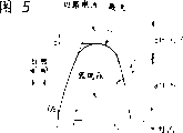
Fig. 5 is a characteristic curve, and the current limitation effect of first embodiment according to the invention circuit breaker is shown.
Fig. 6 is a perspective view, and the internal structure according to the second embodiment of the invention circuit breaker is shown.
Fig. 7 is a profile, and the internal structure according to the second embodiment of the invention circuit breaker is shown.
Fig. 8 is a perspective view, and the profile according to the second embodiment of the invention circuit breaker is shown.
Fig. 9 is a perspective view, and the state that is installed to distribution panelboard according to the first embodiment of the invention circuit breaker is shown.
Figure 10 is a perspective view, and the internal structure according to the third embodiment of the invention circuit breaker is shown.
Figure 11 is a perspective view, and the structure of contact terminal according to the third embodiment of the invention circuit breaker is shown.
Figure 12 is a perspective view, and the structure of contact terminal according to the third embodiment of the invention circuit breaker is shown.
Figure 13 is a perspective view, and the internal structure according to the four embodiment of the invention circuit breaker is shown.
Figure 14 is a perspective view, and the structure according to rotating parts in the fifth embodiment of the invention circuit breaker is shown.
The perspective view that Figure 15 cuts open for part illustrates " connection " state according to the sixth embodiment of the invention circuit breaker.
Figure 16 is a perspective view, and the structure according to holding member and control crank in the sixth embodiment of the invention circuit breaker is shown.
The perspective view that Figure 17 cuts open for part illustrates the off-state according to the sixth embodiment of the invention circuit breaker.
The perspective view that Figure 18 cuts open for part illustrates the tripped condition according to the sixth embodiment of the invention circuit breaker.
Figure 19 is a perspective view, and the engagement according to geared assembly in the sixth embodiment of the invention circuit breaker is shown.
Figure 20 is a perspective view, and the disengaged condition according to geared assembly in the sixth embodiment of the invention circuit breaker is shown.
Figure 21 is a perspective view, and the engagement according to geared assembly in the sixth embodiment of the invention circuit breaker is shown.
Figure 22 is a perspective view, and the disengaged condition according to geared assembly in the sixth embodiment of the invention circuit breaker is shown.
Figure 23 is the perspective view of partly cut-away, and the closure state according to the seventh embodiment of the invention circuit breaker is shown.
Figure 24 is the side cross section view, and the state according to seventh embodiment of the invention circuit breaker mechanical part under closure state is shown.
Figure 25 is the perspective view of partly cut-away, and the off-state according to the seventh embodiment of the invention circuit breaker is shown.
The perspective view that Figure 26 cuts open for part illustrates the tripped condition according to the seventh embodiment of the invention circuit breaker.
With reference now to Fig. 1 to Figure 26, most preferred embodiment of the present invention is described.
Earlier first embodiment of the present invention is described referring to figs. 1 to Fig. 5 and Fig. 9.
Fig. 1 and Fig. 2 provide the structure of this embodiment circuit breaker.In this embodiment, rotating parts made of insulating material 4 is as holding components, relies on to be located substantially on bearing 4c that casing central portion branch provides by rotatably axle journal support in a casing.Casing is by housing 1, and casting moulded closure 2 and side plate 2a form.Figure 1 shows that the state after side plate 2a unloads.On the inner surface of moulded closure 2 and side plate 2a, form bearing 4c.Rotating parts 4 is being installed to base body 1, and cover in the assembly method on it with moulded closure 2 and side plate 2a, can earlier casting moulded closure 2 and side plate 2a be combined, perhaps rotating parts 4 is being packed into from the side, and cover in the assembly method on it with side plate 2a, can earlier housing 1 and moulded closure 2 be combined.
As the moving contact matrix 5a of first moving-conductor and as the moving contact matrix 5b of second moving-conductor by rotating parts 4 fixing supports. Moving contact matrix 5a and 5b are by being clamped on the rotating parts 4 on the formed thrust 4d and 4e, also can be by being assembled in the groove that on rotating parts 4, forms, be secured on the rotating parts 4, wherein, moving contact matrix 5a and 5b rely on the thrust 4d of rotating parts 4 and the resilience force of 4e, perhaps rely on spiral positioning to be secured on the rotating parts 4 to the way of rotating parts 4.In this embodiment, thrust 4d is positioned at the back side of moving contact matrix 5a and 5b upper contact head 6, and thrust 4e then is positioned at the homonymy of contact 6, and contact matrix 5a and 5b are clamped between them.Thrust 4d prevents because contact pressure makes the distortion of each moving contact matrix also as holding components.Contact 6 is arranged as moving contact on each moving contact matrix 5a and the 5b, use silver brazing, riveted joint or similar approach are attached to the two ends of contact matrix.Rotating parts 4 rotates as the center of circle with pivot 4a, and pivot 4a is formed by rotating parts 4 integral body, or is formed by the pin that passes rotating parts 4.Operating grip 3 is installed on the rotating parts 4, and give prominence in the outside of moulded closure 2 at its top, because the branch/closing operation of operating grip 3, making rotating parts 4 is that (in Fig. 1, clockwise direction is for disconnecting, counterclockwise for connecting) rotated in the center of circle with pivot 4a.In this embodiment, because binding post, operating grip and profile and existing circuit breaker compatibility, condition without limits from the angle of use circuit breaker does not influence the convenience of use.
Fixed contact matrix 8 as first fixed conductor, at the one end mains side binding post 8a is arranged, the other end is attached with the contact 6 as fixed contact, and it is to use silver brazing, and riveted joint or similar approach are attached on the position relative with moving contact on the moving contact matrix 5a.Center fixed contact matrix 7 as the center fixed conductor is being fixed in below the rotating parts 4 on the housing 1, use silver brazing, riveted joint or other similar approach will be as the contact 6 of fixed contact attached on the positions relative with the moving contact of moving contact matrix 5a and 5b, its two ends.The position that center fixed contact matrix 7 is installed on the housing 1 falls in, and is convenient to location fixedly the time.In addition, because the thickness of this place plate reduced compared with other parts, the heat that is produced by center fixed contact matrix can be by installing dull and stereotyped 80 contact with equipment, looses effectively and install on the flat board 80 to the equipment of distribution panelboard as shown in Figure 9.Use silver brazing on the load side conductor 9 as second fixed conductor, riveted joint or similar approach will be attached to as the contact 6 of fixed contact on the one end position relative with moving contact on the moving contact matrix 5b, and load side binding post 9a is arranged on the other end.Fixed contact matrix 8, moving contact matrix 5a, 5b, the writing board shape that center fixed contact matrix 7 and load side conductor 9 are respectively made for the rigid conductive material, for example dull and stereotyped copper bar or similar material.Electric conducting material has more than and is confined to copper, also can be other metal as copper alloy, for example ooze iron copper or aluminium, as long as material is good conduction, heat carrier, and suitably elasticity allows that contact collides.In this embodiment, on mains side binding post 8a and the load side binding post 9a terminal metal 10 is arranged, use screw-clamped respectively so that when it is assembled to distribution panelboard, make link the there lead 82 and 84 terminal fix.
Figure 1 shows that the on-state of circuit breaker, under the situation of this state manual brake separating operation, operating grip 3 moves right in the drawings, because rotating parts clockwise rotates, opens substantially simultaneously at four locational moving contacts and fixed contact.The closing by hand operation is opposite with the action of sub-switching operation, and at this moment, operating grip 3 is moved to the left in the drawings from the separating brake position, because rotating counterclockwise of rotating parts contacts with fixed contact simultaneously at four locational moving contacts.
In this embodiment, because fixed contact matrix 8, moving contact matrix 5a and 5b, the writing board shape that center fixed contact matrix 7 and load side conductor 9 are respectively made for the rigid conductive material, can save the flexible line conductor of using in the existing circuit breaker of great majority, thereby eliminated the existing problem of existing circuit breaker, for example, the problem that the flexible line conductor in limiting circuit breaker life-span is become flexible or disconnected.
In this embodiment, with 4 o'clock structure of contact terminal rotary contacts of series connection minute/close mechanism.In rotary-type structure, do not need crank connecting link to connect or similar means, can simplify the mechanical part of circuit breaker widely, thereby improve assembly performance, and reduce product cost.In addition, simplifying greatly the life-span that prolongs circuit breaker owing to mechanical part.
And then, because the arc energy of 4 structure of contact terminals of series connection when reducing the utmost point widely and opening just can suppress the generation of electric arc on each contact, thereby save arc-control device, perhaps dwindle the size of arc-control device widely.At this moment, when cutting-off of short-circuit electric current,, select the lead supporting structure for the user because 4 structure of contact terminals of series connection have suppressed short circuit current widely, the thermal capacity of load equipment, and the top/bottom latitude of circuit breaker is without limits, for the user provides very big benefit.
Cut-off phenomenon when illustrating by circuit breaker cutting-off of short-circuit electric current with reference to figure 3 to Fig. 5.
When short trouble having occurred in the circuit, big electric current flows through circuit.Because the repulsion of big electric current is opened when contact, when suppressing short circuit current, just produces arc voltage between contact, this just is referred to as current limliting, and breaker mechanism moves subsequently, bears the recovery voltage between the contact, and finishes disconnection.
Figure 3 shows that the circuit diagram of the equivalent circuit when short trouble takes place.In the case, set up following equation
(formula 1)
 I wherein: short circuit current (A)
e
0: current/voltage amplitude (V)
R: circuitous resistance (Ω)
L: circuit inductance (H)
Va: arc voltage (V)
ω: supply voltage angular frequency (Hz)
θ: short circuit phase place (rad)
Arc voltage Va is subjected to the influence of moving contact matrix displacement the most significantly.As the result of various experiences, arc voltage is approximate as shown in Figure 4, and it can formula (2), and (3) and (4) are represented.
(formula 2)
As 0≤t≤t
1The time
Va=0 (formula 2)
(formula 3)
Work as t
1<t≤t
2The time
Va=Vo+a (t-t
1) (formula 3)
(formula 4)
Work as t
2During<t
Va=V
0+ a (t-t
1)+b (t-t
2)
2(formula 4)
By formula (5), calculate (6) and (7) at each cut-off current constantly.
(formula 5)
When≤t≤t
1The time
 In the formula
(formula 6)
Work as t
1<t≤t
2The time

(formula 7)
Work as t
2During<t
(formula 7)
Never the electric current (short circuit current of estimation) during arc voltage deducts the formula V that is represented to limit electric current by the generation of arc voltage
0, a (t-t
1) and b (t-t
2)
2, obtain formula (5), (6) and (7).
With formula (8), (9) and (10) represent current limliting.
(formula 8)
V
0Current limliting iv
0
(formula 9)
A (t-t
1) current limliting ia

(formula 10)
B (t-t
2)
2Current limliting ib
 Find out from the above, suppose that the short stream of short circuit of estimation is i
0, each cut-off current iv constantly
0, ia and ib such as formula (11), shown in (12) and (13), iv
0, ia and ib have limited the short circuit current estimated as shown in Figure 5.
Find out from the above, suppose that the short stream of short circuit of estimation is i
0, each cut-off current iv constantly
0, ia and ib such as formula (11), shown in (12) and (13), iv
0, ia and ib have limited the short circuit current estimated as shown in Figure 5.
(formula 11)
As 0≤t≤t
1The time
I=i
0(formula 11)
(formula 12)
Work as t
1<t≤t
2The time
I=i
0-(iv
0+ ia) (formula 12)
(formula 13)
Work as t
2During<t
I=i
0-(iv
0+ ia+ib) (formula 13)
Further, after i is multiply by at formula (1) two ends, be integrated to and cut-off the concluding time, as the formula (14).
Circuit energy:
Supply with from power supply
Energy (formula 14) wherein

As can be seen, the energy that is provided by power supply is divided into energy and the arc energy that consumes in the circuit from formula (14), and the latter consumes in arc-extinguishing chamber of circuit breaker.
Find out the rising (t of arc voltage from above-mentioned
1, t
2, a, b) thermal capacity with arc control device has determined the characteristic that circuit breaker cut-offs.
Correspondingly, in order to improve break performance, the rising that can make arc voltage at least more earlier, in the circuit breaker of a plurality of structure of contact terminals of series connection, break performance has been improved significantly.
In simple terms, in 2 series connection structure of contact terminals of a same structure, according to the approximate arc voltage of numerical computations, the arc energy that is produced nearly is suppressed to for whole 2 contacts
 , each arc-control device is just enough as long as consume 1/4 arc energy.
And then, owing to increasing the contact number arc energy is reduced, along with the contact logarithm increases, cut-off distance relatively with needed under the rated current that provides in the table 1, the actual distance of cut-offfing has shortened.
(table 1)
The relation of cut-offfing distance of contact number and circuit breaker
(for the 30A structure) needed actual the cut-offfing of each contact of contact number of rated current (structure) cut-off distance (right the cut-offfing apart from distance of contact
(mm) number) (mm) from (B)
(N) (B/N)
(mm)30A 12 1 12 1230A 12 2 5.4 10.830A 12 4 2.42 9.730A 12 6 1.45 8.7
Actual distance=required distance * 0.9 (N-1) that cut-off that cut-off
Second embodiment of the present invention will describe with reference to figure 6 to Fig. 8.In first embodiment (Fig. 1 and Fig. 2), provided the example of single-pole circuit breaker.And in the present embodiment, the two poles of the earth product is built in the box.Box is by housing 21, and moulded closure 22 and side panel 2a form, and it is first fixed conductor that each utmost point disposes fixed contact matrix 8; Moving contact matrix 5a is first moving-conductor; Center fixed contact matrix 7 is the center fixed conductor; Moving contact matrix 5b is second moving-conductor, and load side conductor 9 is second fixed conductor, and the two poles of the earth are positioned at the both sides of rotating parts 24 abreast.In this embodiment, forming insulation barrier 22a respectively between the mains side binding post 8a and between the load side binding post 9a, as the electrode insulation between the two poles of the earth.As shown in Figure 7, the pivot point of rotating parts 24 is positioned at pivot 24a, and this center relies on the bearing 24c that forms on moulded closure 22 and the side plate 2a inner surface and supports.Moving contact matrix 5a and 5b are secured on formed thrust 4d and 4e (not shown in Fig. 6) on the rotating parts 24, are fixed on the rotating parts 24, and its mode is identical with first embodiment.In addition, in this embodiment, thrust 4d is positioned at the back side of the contact 6 on moving contact matrix 5a and the 5b, and thrust 4e then is positioned at the homonymy of contact 6, and moving contact matrix 5a and 5b are clamped on (not shown in Fig. 6) between them.In the present embodiment, current transformer 11 also is housed on load side conductor 9, overcurrent sensing circuit 12 is supplied with in the output of current transformer 11, under overcurrent condition, output by overcurrent sensing circuit 12 drives over current trip 13, and plug 13a is stretched out, and promotes the drive part 4b of rotating parts 24, turn parts 24 just clockwise rotate, and open four locational contacts substantially simultaneously.
The structure of other parts is identical with first embodiment basically.In the present embodiment, the moving contact matrix 5a at the two poles of the earth, 5b can be operated simultaneously by a rotating parts 24.Be easy to further promote the use of three utmost points and four utmost point products, can fully adapt to the three-stage structure of common employing, the profile of three-stage structure also is shown except two electrode structures among Fig. 8.
Illustrate according to the 3rd embodiment of the present invention to Figure 12 with Figure 10.This embodiment has provided structure of contact terminal has been made current limliting repulsion type.Improve the example of break performance further.Figure 10 illustrates the entire infrastructure of this embodiment.Present embodiment has identical part and identical structure with first embodiment, and different is fixed contact matrix 28, center fixed contact matrix 27, load side conductor 29, housing 31 and moulded closure 32.In the present embodiment, at fixed contact matrix 28, center fixed contact matrix 27, form a U-lag on each fixed conductor of load side conductor 29 near the fixed contact, round fixed contact, make current opposite in direction on the sense of current and the moving-conductor to form lug 28b respectively in the inside of U-lag, 27a, 29b.Lug 28b, 27a and 29b can make the direction that mutual electric current passes through between conductor and the moving-conductor that is relatively fixed opposite, so, (when producing short circuit current) is under the effect of electromagnetic force when big electric current flows through, just add repulsive force between fixed contact and the moving contact, the utmost point is opened earlier, thereby the effect of obvious inhibition short circuit current (current limliting) is provided.Figure 11 is the details drawing of part A.Part A provides the relative part between center fixed contact matrix 27 and the moving contact matrix 5a, wherein because the sense of current B of influence on mobile contact matrix 5a of lug in U-lag and the center fixed contact matrix 27
1With the sense of current B on the lug 27a
2Opposite each other, just produce electromagnetic repulsive force.In addition, except U-lag, can also make center fixed contact matrix 27 bend to the U-shaped structure as shown in figure 12, form current limliting and repel structure, the sense of current B on the moving contact matrix 5a
1With the sense of current B on the crooked lug 27a of U-shaped
2On the contrary, thus produce electromagnetic repulsive force.
With reference to Figure 13 the 4th embodiment of the present invention is described.In this embodiment, three moving- conductor 55a, 55b and 55c and two center fixed conductor 57a, 57b is placed in the box of being made up of housing 51 and moulded closure 52.In the present embodiment, improve with three pairs of contacts and cut-off characteristic.Other parts and first embodiment are identical.
With reference to Figure 14 the 5th embodiment of the present invention is described.In this embodiment, the disc of the structure of rotating parts from other embodiment replaces to the rotating parts 74 that is essentially the X-shaped structure.The pivot 74a of rotating parts 74 is that dependence bearing 4c and 24c are rotating fulcrum, just as other embodiment.Be formed with thrust 74d on rotating parts 74,74e is used to tighten mobile contact matrix 5a and 5b.Thrust 74d is positioned at the back side of moving contact matrix 5a and 5b upper contact head 6, and thrust 74e then is positioned at the same side of contact 6.Thrust 74d prevents because contact pressure makes each moving contact matrix distortion also as holding components.Other parts then can adopt among first to the 3rd embodiment parts in any one.
Illustrate according to a sixth embodiment of the present to Figure 22 with reference to Figure 15.
Figure 15 has provided the breaker structure of this embodiment, is depicted as on-state.The circuit breaker of this embodiment includes fixed contact matrix 111 as first fixed conductor in the box inside of being made up of housing 101 and moulded closure 102, and the one end is connected on the power supply terminal 111-a, and the first fixed contact 112-a is arranged on the other end; Conductor 113 is as second fixed conductor, and the one end is connected on the load binding post 113-b, and the second fixed contact 112-b is arranged on the other end; The first moving contact 106-a and the second moving contact 106-b are arranged on the moving contact matrix 105, relative with the first fixed contact 112-a respectively with the second fixed contact 112-b; Rotor 104 is as holding components, is that rotate in the center of circle with rotating shaft 104-b, is used to support moving contact matrix 105, makes win moving contact 106-a and the second moving contact 106-b and the first fixed contact 112-a with second fixed contact 112-b contact with separate; Operating grip 103 rotates with the rotating shaft coaxle of rotor 104, is used to realize branch/closing operation of the first moving contact 106-a and the second moving contact 106-b; Current transformer 114 and overcurrent sensing circuit 115 are used for detecting the overcurrent condition of the electrical path from power supply terminal 111-a to load binding post 113-b as overcurrent detecting device; Trip unit 116 is as tripgear, according to the output action of overcurrent detecting device; Torsion spring 107 is used for driving rotor 104 in the tripping operation direction as drive unit; Link up with 108 in addition as geared assembly, rotor 104 is engaged to operating grip 103 gets on.
Carry out closing/minute operation of circuit breaker with the operating grip of giving prominence to outside moulded closure 102 103.As shown in figure 16, lever operated part 103a is arranged at operating grip top, protrusion 103-c is arranged as center of rotation under it, and extension 103-b stretches out to the right in addition, and there is a groove 103d upper end of extension 103-b.Protrusion 103-c rotatably is assembled on the rotor 104.Rotor 104 is that rotate at the center with projection 104-b, and the assembled portion between handle 103 and rotor 104 has a torsion spring 107, and when handle fixedly the time, torsion spring 107 clockwise rotates it to rotor 104 energy.As the extension on the operating grip 103, the upper right side of rotor 104 has the 104-c of extension portion.On the 104-c of extension, form a groove 104-d, be used for adorning hook 108.Hook 108 is done the pivot support by pin 110.In addition, see that hook 108 relies on spring 109 accumulation of energy along clockwise direction from above.One end of hook 108 has drive part 108-b, and the other end has mate 108-a.In the normal state, hook mate 108-a stretches to the operating grip 103 that is driven by spring 109 from groove 104-d, rotor 104 and operating grip 103 engagements, and along with operating grip 103 rotates together.One moving contact matrix 105 is arranged on the rotor 104, have moving contact 106-a and 106-b along a string that with main 104-b in rotating is the circle in the center of circle.Extension 104-a is arranged on the rotor 104, cover the extension side, the cardinal extremity of operation part 103-a on the operating grip 103.In this embodiment, be marked with letter " ON ", place the opening part of handle at (ON) state of connecting on by moulded closure 102 and can see this letter at extension 104-a.With operation part 103-a extension opposite position, base portion 103-e is marked with letter " OFF " on operating grip 103, under off-state, can see it is these letters by the opening part of placing handle on the moulded closure 102.In addition, the base portion 103-f of the extension side of operation part 103-a is marked with letter " TRIP " on the operating grip 103, they are covered by extension 104-a on the rotor 104 usually and hide, because the mobile of extension 104-a caused under the tripped condition, just can see these letters by the opening part of placing handle on the moulded closure 102.
As shown in figure 15, an end of fixed contact matrix 111 is with power supply terminal 111-a, and this matrix 111 is essentially Z-shaped construction stretch, and the other end is with fixed contact 112-a.On the other hand, an end of conductor 113 is with load binding post 113-b, and it is essentially L shaped construction stretch, and the other end is with fixed contact 112-b.Fixed contact 112-a is installed on the position relative with 106-b with moving contact 106-a with 112-b, leaves equidistant from distance, as the spacing that moving contact is installed.In Figure 15, rotor 104 clockwise rotates opens contact.Open for the rotation that relies on rotor 104 makes moving contact 106-a and 106-b divide with fixed contact 112-a and 112-b, it is that the center of circle is on the right half part at last two the string centers of circle of radius to mobile contact 106-a surface distance substantially that moving contact matrix 105 can be attached to pivot 104-b with rotor 104.Radially (from mobile contact 106-a to the 106-b direction) length setting of mobile contact matrix 105 is half less than chord length.
On the inner surface of moulded closure 102, form thrust 101-b, as the bearing of extension 103-b, so that closing/during minute conversion, stop the rotation of handle 103.Thrust 101-b does not draw in Figure 17 and Figure 18.
Further, spring 130 is housed on handle 103, so as to divide, the quick acting during closing operation.The other end of spring 130 hangs on the thrust 101-a of housing 101.
Figure 17 shows that the off-state of circuit breaker among this embodiment.Lever operated part 103-a overturn to the right from state shown in Figure 15 carry out opening operation.When lever operated part 103-a when right is overturn, whole movable part such as the handle 103 shown in Figure 16, rotor 104, the hook 108, clockwise rotate as pivot with the rotor 104 upper process thing 104-b that are assemblied on the housing 101.Because the rotation of handle 103, the upper end of spring 107 moves right, and when the center line of spring 107 surpasses the center of rotor thrust 104-b, only depends on the resilience of spring force direction that whole movable part is promptly rotated.When movable part further rotated, handle portion 103-b was by the thrust 101-b stop on the housing, and rotation just stops.
Figure 18 shows that the circuit breaker trip state of present embodiment.Current transformer 114 detects main circuit current, and its output is sent in the overcurrent sensing circuit 115.If electric current surpasses the rated current in the main circuit, judge the overcurrent value by overcurrent sensing circuit 115, then, send a characteristic triggering signal that defines in the inverse time lag mode as the output that is used to trip, to trip unit 116 from overcurrent sensing circuit 115.The operating part 116-a of trip unit 116 promotes the drive part 108-b of hook 108 because triggering signal occurs suddenly.Figure 19 to Figure 22 illustrates the action of hook 108.Figure 19 and Figure 21 are that circuit breaker is at the state that switches on and off state lower draw-bar 108.Figure 19 is hook 108 states on rotor 104, and Figure 21 is hook 108 and handle groove 103-d engagement.Under this state, because drive part 108-b is not subjected to the pressure of operating part 116-a, the mate 108-a on the hook stretches out from the groove 104-d of rotor 104, as shown in Figure 19, and the groove 103-d on the engagement handle, as shown in figure 21.The pin 110 that do not draw among Figure 19, rotor 104 does not draw among Figure 21.Figure 20 and Figure 22 are the state of circuit breaker trip state lower draw-bar.Figure 20 shows that hook 108 states on rotor 104, Figure 22 is hook 108 and handle groove 103-d engagement.When overcurrent takes place, owing to popping, operating part 116-a promotes to link up with 108 drive part 108-b, with the opposite direction of spring 109 accumulation of energys, rotate (seeing from above counterclockwise) around pinning 110 for center of rotation, as shown in figure 20 for hook 108.Hook mate 108-a breaks away from the groove 103-d of handle, as shown in figure 22, has just discharged the engagement between handle 103 and the rotor 104.Then, rotor 104 is that pivot clockwise rotates with the assembled portion of protrusion 103-c on the handle under the elastic force effect of spring 130, so make moving contact 106-a, 106-b leaves fixed contact 112-a and 112-b, and the contact open mode is provided, thereby circuit is cut-off.In this case, owing to rotor 104 can be in the motion of tripping operation direction, irrelevant with the operation of operating grip 103, shape still can trip if operating grip 103 is locked in the connection shape, just but the circuit breaker of acquisition free-handle.
And then, in this case, only rely on the rotation of rotor 104 that extension 104-a is moved, letter under covering " TRIP " is just located to show by moulded closure 102 upper handle openings (edge) on operating grip 103 base portion 103-f.
This embodiment can reduce the mechanical part number of parts significantly and improve assembly performance, and then reduces the cost of product widely, on the other hand, has improved reliability of products owing to number of parts reduces.
The circuit breaker of seventh embodiment of the invention is described with reference to Figure 23 to Figure 26.This embodiment is applied to big relatively value (the 225A structure is to the 400A structure).
Figure 23 and Figure 24 illustrate overall structure respectively and the structure of critical piece under the on-state of contact closure.
The circuit breaker of this embodiment comprises that fixed contact matrix 211 is as mains side first fixed conductor; Conductor 213 is as load side second fixed conductor; Fixed contact matrix 207 as the center fixed conductor, places between first fixed conductor and second fixed conductor; Moving contact matrix 205 as first moving-conductor, places between contact matrix 211 and the fixed contact matrix 207; Moving contact matrix 206 as second moving-conductor, places between fixed contact matrix 207 and the conductor 213; Rotor 204 is rotatably arranged as holding components, to support moving contact matrix 205 and 206.In addition, it also comprises heating member 122 and bimetal leaf 125; Also have fixed iron core 123 and moving unshakable in one's determination 124 as overcurrent detecting device, be used for detecting overcurrent condition in 213 electrical path from fixed contact matrix 211 to conductor; Hook 208 is as tripgear, and according to the current sensing means output action, when tripgear moved, rotor 204 is in the action of tripping operation direction, and was irrelevant with the operation of operating grip 230.
Because the operating physical force of large capcity breaker is big, strengthen with metallic handlebar 117 in the handle 230.U-lag 117-a on the handlebar is coupled on the protrusion 118-a as the fixed mount 118 of make-up machinery part pedestal, is that rotate in the center of circle with protrusion 118-a.In addition, hook 208 relies on pin to be fixed on the fixed mount 118 at hook hole 208-a place, and can rotate.Hook top 208-b and 119 engagements of tripping operation metal.Tripping operation metal 119 relies on pins to support on the fixed mount 118, and that works rotates as hook 208.The other end of tripping operation metal 119 is engaged on the interlock plate 120.Make tripping operation metal 119 and interlock plate 120 clockwise direction accumulation of energys by spring 132.The center of rotation 204-a of rotor 204 also is assembled on the fixed mount 118.Two ends are attached with moving contact 112-a respectively, and 112-b and moving contact matrix 206 are installed on the rotor 204, so that stop is attached to the fixed contact 106 on the fixed contact matrix 211 and the second contact matrix 207.
The fixed contact 106-d that conductor 213 tops are adhered to is leaning terminal moving contact 112-d.The other end of conductor 213 and heating member 122 connect, and the other end of heating member then constitutes load side binding post matrix 122-b.Fixed iron core 123 and moving unshakable in one's determination 124 is arranged in around the conductor, and bimetal leaf 125 links with heating member 122, at the top of bimetal leaf 125 set screw 126 is housed.
In addition, between handlebar 117 and rotor 204, connect with spring 130.
Rely on bar 133 will link up with 208 and rotor 204 composition connecting rods.、
The state of opening for contact that cut-offs shown in Figure 25.For cut-offfing operation, when handle 230 and second embodiment same way as are operated,, thereby open contact to the right because the direction of the power of spring 130 clockwise rotates rotor 204.
Shown in Figure 26 is tripgear.When having overcurrent to flow through in the main circuit, make bimetal leaf 125 heating by heating member 122, electric current in the overload scope makes bimetal leaf 125 distortion, perhaps attract moving unshakable in one's determination 124 at short circuit current scope internal fixation unshakable in one's determination 123, junction panel 120 is rotated counterclockwise and metal 119 disengagements of tripping, tripping operation metal 119 just clockwise rotates.Just discharge owing to rotate and link up with the engagement at top 208, hook 208 just is center of circle rotation with 208-a, acts on owing to connect the bar 133 of hook 208 and rotor 204, and rotor 204 turns clockwise, and contact is opened.Handle 230 and handlebar 117 are that the center of circle turns right with protrusion 118-a on the fixed mount 118, withstand on the protrusion 208-b of hook 208, stop to connect and cut-off between the position, and handle 230 indicates TRIP shown on the centre position.
This embodiment is applicable to the circuit breaker of big relatively value, because the overcurrent detection system is mechanical, its structure relatively reduces cost.And then, because it is four contact systems, the break performance that can obtain.
Claims (8)
1. circuit breaker, comprise fixed conductor and moving-conductor, it is characterized in that, described fixed conductor comprises first fixed conductor of mains side, second fixed conductor of load side and place first fixed conductor and second fixed conductor between the center fixed conductor, described moving-conductor comprises first moving-conductor that places between described first fixed conductor and the described center fixed conductor, places second moving-conductor between described center fixed conductor and described second fixed conductor.
2. the described circuit breaker of claim 1, it is characterized in that, provide branch/close mechanism, make described first and described second between described first fixed conductor and the described center fixed conductor and between described center fixed conductor and described second fixed conductor move conductor and divide respectively simultaneously basically/close.
3. the described circuit breaker of claim 2, it is characterized in that, described first and described second moving-conductor each be attached to basic on the holding components made of insulating material with the electric insulation state, the branch of being joined/close mechanism to make rotatablely moving of described holding components drive described moving-conductor around the rotating shaft rotation, thus carry out the branch/closing operation between each fixed conductor and the described moving-conductor effectively.
4. circuit breaker, comprise fixed conductor and moving-conductor, it is characterized in that, described fixed conductor comprises first fixed conductor of mains side, second fixed conductor of load side and be inserted in first fixed conductor and second fixed conductor between one or more (N) center fixed conductor, described moving-conductor comprises a plurality of (N+1), and moving-conductor places between each described fixed conductor.
5. circuit breaker comprises a shell, fixed conductor, moving-conductor, places near the contact part the lateral edges of each conductor and be used to rotate described moving-conductor so that the branch that each described contact is partly divided/closes/closing operation mechanism substantially simultaneously,
It is characterized in that, described moving-conductor rotates around rotating shaft in described shell, described fixed conductor comprises mains side first fixed conductor of relative moving-conductor one end, load side second fixed conductor of the described relatively moving-conductor other end, described contact partly makes described first fixed conductor, described moving-conductor and described second fixed conductor are electric goes up series connection, and described branch/closing operation mechanism provides the action bars that stretches out by on the described outer casing top surface outside shell.
6. circuit breaker as claimed in claim 5 is characterized in that, described moving-conductor is arranged in described rotating shaft to be had on the position of spacing, and making does not have electric conductor near the described rotating shaft.
7. circuit breaker, comprise fixed conductor, moving-conductor, one be used for supporting the holding components, one of described moving-conductor be used for to electrical path divide/operating grip of closing operation, one be used to detect described electrical path overcurrent condition overcurrent detecting device and based on the tripgear of the output function of overcurrent detecting device
It is characterized in that described fixed conductor comprises first fixed conductor of mains side; Second fixed conductor of load side, described moving-conductor place between described first fixed conductor and described second fixed conductor; Described electrical path is extended to described second fixed conductor from described first fixed conductor, and, the operation of described operating grip when described holding components is independent of the tripgear action in the action of tripping operation direction.
8. circuit breaker, comprise fixed conductor, moving-conductor, one be used for supporting the holding components, one of described moving-conductor be used for to electrical path divide/operating grip of closing operation, one be used to detect described electrical path overcurrent condition overcurrent detecting device and based on the tripgear of the output function of overcurrent detecting device
It is characterized in that described fixed conductor comprises first fixed conductor of mains side; Second fixed conductor of load side; Place the center fixed conductor between described first fixed conductor and described second fixed conductor, described moving-conductor comprises first moving-conductor that places between described first fixed conductor and the described center fixed conductor; Place second moving-conductor between described center fixed conductor and described second fixed conductor; Described electrical path is extended to described second fixed conductor from described first fixed conductor, and, the operation of described operating grip when described holding components is independent of the tripgear action in the action of tripping operation direction.
Applications Claiming Priority (4)
| Application Number | Priority Date | Filing Date | Title |
|---|---|---|---|
| JP12607694A JP3228002B2 (en) | 1994-06-08 | 1994-06-08 | Circuit breaker |
| JP126076/94 | 1994-06-08 | ||
| JP22449694A JPH0887945A (en) | 1994-09-20 | 1994-09-20 | Circuit breaker |
| JP224496/94 | 1994-09-20 |
Publications (2)
| Publication Number | Publication Date |
|---|---|
| CN1117200A CN1117200A (en) | 1996-02-21 |
| CN1052810C true CN1052810C (en) | 2000-05-24 |
Family
ID=26462316
Family Applications (1)
| Application Number | Title | Priority Date | Filing Date |
|---|---|---|---|
| CN95107358A Expired - Fee Related CN1052810C (en) | 1994-06-08 | 1995-06-08 | Circuit breaker |
Country Status (2)
| Country | Link |
|---|---|
| CN (1) | CN1052810C (en) |
| TW (1) | TW282549B (en) |
Families Citing this family (2)
| Publication number | Priority date | Publication date | Assignee | Title |
|---|---|---|---|---|
| US8350168B2 (en) * | 2010-06-30 | 2013-01-08 | Schneider Electric USA, Inc. | Quad break modular circuit breaker interrupter |
| JP5862818B1 (en) * | 2015-01-30 | 2016-02-16 | ソニー株式会社 | Current limiting circuit, DC power supply connector, and DC power supply device |
Citations (1)
| Publication number | Priority date | Publication date | Assignee | Title |
|---|---|---|---|---|
| US4771140A (en) * | 1986-09-11 | 1988-09-13 | Mitsubishi Denki Kabushiki Kaisha | Circuit interrupter |
-
1995
- 1995-05-16 TW TW84104828A patent/TW282549B/zh active
- 1995-06-08 CN CN95107358A patent/CN1052810C/en not_active Expired - Fee Related
Patent Citations (1)
| Publication number | Priority date | Publication date | Assignee | Title |
|---|---|---|---|---|
| US4771140A (en) * | 1986-09-11 | 1988-09-13 | Mitsubishi Denki Kabushiki Kaisha | Circuit interrupter |
Also Published As
| Publication number | Publication date |
|---|---|
| CN1117200A (en) | 1996-02-21 |
| TW282549B (en) | 1996-08-01 |
Similar Documents
| Publication | Publication Date | Title |
|---|---|---|
| EP1876615B1 (en) | Electrical switching apparatus contact assembly and movable contact arm therefor | |
| JP4629754B2 (en) | Low voltage circuit breaker | |
| CN1918679A (en) | Switch and device using the switch | |
| CN101036211A (en) | Systems, methods, and device for actuating a circuit breaker | |
| CN107731580B (en) | Automatic change-over switch electrical apparatus and contact assembly thereof | |
| CN107004527B (en) | Low section meltability separating switch device | |
| CN1052810C (en) | Circuit breaker | |
| EP2290667B1 (en) | Slide type movable contactor assembly for circuit breaker | |
| CN107396609B (en) | A kind of brush DC switch | |
| CN1040922C (en) | Movable contactor device in circuit breaker | |
| CN210296138U (en) | Isolating switch | |
| KR101579698B1 (en) | Circuit breaker | |
| CN211828620U (en) | Primary and secondary fusion modular switch mechanism | |
| CN1043222A (en) | Be used for the device that the limiting circuit breaker joystick moves | |
| EP3217413B1 (en) | Electric switch with high thermal performance, and method for cutting off an electrical current | |
| CN108133868B (en) | Direct current contactor contact system | |
| CN209804496U (en) | micro switch | |
| CN101620955B (en) | Method for locking contacts of low-voltage circuit breaker | |
| CN211479970U (en) | Contact structure of molded case circuit breaker | |
| KR200377715Y1 (en) | A Connecting Device Between Cubicle Type SF6 Gas Insulated Switchgear And Vacuum Interupter | |
| CN1357154A (en) | Fuse switch | |
| CN217485390U (en) | Electromagnetic system and circuit breaker | |
| CN210535533U (en) | Brushless motor integrated switch | |
| US5584379A (en) | Disconnect switch double motion mechanism | |
| CN217280662U (en) | Moving contact assembly |
Legal Events
| Date | Code | Title | Description |
|---|---|---|---|
| C06 | Publication | ||
| PB01 | Publication | ||
| C10 | Entry into substantive examination | ||
| SE01 | Entry into force of request for substantive examination | ||
| C14 | Grant of patent or utility model | ||
| GR01 | Patent grant | ||
| C17 | Cessation of patent right | ||
| CF01 | Termination of patent right due to non-payment of annual fee |
Granted publication date: 20000524 Termination date: 20100608 |