CN105226314B - Heat recovery and temperature control for underwater vehicles utilizing fuel cells - Google Patents
Heat recovery and temperature control for underwater vehicles utilizing fuel cells Download PDFInfo
- Publication number
- CN105226314B CN105226314B CN201510379060.3A CN201510379060A CN105226314B CN 105226314 B CN105226314 B CN 105226314B CN 201510379060 A CN201510379060 A CN 201510379060A CN 105226314 B CN105226314 B CN 105226314B
- Authority
- CN
- China
- Prior art keywords
- temperature
- outlet
- fuel cell
- solid oxide
- cathode
- Prior art date
- Legal status (The legal status is an assumption and is not a legal conclusion. Google has not performed a legal analysis and makes no representation as to the accuracy of the status listed.)
- Active
Links
Images


Classifications
-
- H—ELECTRICITY
- H01—ELECTRIC ELEMENTS
- H01M—PROCESSES OR MEANS, e.g. BATTERIES, FOR THE DIRECT CONVERSION OF CHEMICAL ENERGY INTO ELECTRICAL ENERGY
- H01M8/00—Fuel cells; Manufacture thereof
- H01M8/10—Fuel cells with solid electrolytes
-
- H—ELECTRICITY
- H01—ELECTRIC ELEMENTS
- H01M—PROCESSES OR MEANS, e.g. BATTERIES, FOR THE DIRECT CONVERSION OF CHEMICAL ENERGY INTO ELECTRICAL ENERGY
- H01M8/00—Fuel cells; Manufacture thereof
- H01M8/06—Combination of fuel cells with means for production of reactants or for treatment of residues
- H01M8/0606—Combination of fuel cells with means for production of reactants or for treatment of residues with means for production of gaseous reactants
- H01M8/0612—Combination of fuel cells with means for production of reactants or for treatment of residues with means for production of gaseous reactants from carbon-containing material
- H01M8/0618—Reforming processes, e.g. autothermal, partial oxidation or steam reforming
-
- B—PERFORMING OPERATIONS; TRANSPORTING
- B63—SHIPS OR OTHER WATERBORNE VESSELS; RELATED EQUIPMENT
- B63G—OFFENSIVE OR DEFENSIVE ARRANGEMENTS ON VESSELS; MINE-LAYING; MINE-SWEEPING; SUBMARINES; AIRCRAFT CARRIERS
- B63G8/00—Underwater vessels, e.g. submarines; Equipment specially adapted therefor
- B63G8/36—Adaptations of ventilation, e.g. schnorkels, cooling, heating, or air-conditioning
-
- F—MECHANICAL ENGINEERING; LIGHTING; HEATING; WEAPONS; BLASTING
- F02—COMBUSTION ENGINES; HOT-GAS OR COMBUSTION-PRODUCT ENGINE PLANTS
- F02G—HOT GAS OR COMBUSTION-PRODUCT POSITIVE-DISPLACEMENT ENGINE PLANTS; USE OF WASTE HEAT OF COMBUSTION ENGINES; NOT OTHERWISE PROVIDED FOR
- F02G1/00—Hot gas positive-displacement engine plants
- F02G1/04—Hot gas positive-displacement engine plants of closed-cycle type
- F02G1/043—Hot gas positive-displacement engine plants of closed-cycle type the engine being operated by expansion and contraction of a mass of working gas which is heated and cooled in one of a plurality of constantly communicating expansible chambers, e.g. Stirling cycle type engines
-
- H—ELECTRICITY
- H01—ELECTRIC ELEMENTS
- H01M—PROCESSES OR MEANS, e.g. BATTERIES, FOR THE DIRECT CONVERSION OF CHEMICAL ENERGY INTO ELECTRICAL ENERGY
- H01M8/00—Fuel cells; Manufacture thereof
- H01M8/04—Auxiliary arrangements, e.g. for control of pressure or for circulation of fluids
-
- H—ELECTRICITY
- H01—ELECTRIC ELEMENTS
- H01M—PROCESSES OR MEANS, e.g. BATTERIES, FOR THE DIRECT CONVERSION OF CHEMICAL ENERGY INTO ELECTRICAL ENERGY
- H01M8/00—Fuel cells; Manufacture thereof
- H01M8/04—Auxiliary arrangements, e.g. for control of pressure or for circulation of fluids
- H01M8/04007—Auxiliary arrangements, e.g. for control of pressure or for circulation of fluids related to heat exchange
- H01M8/04014—Heat exchange using gaseous fluids; Heat exchange by combustion of reactants
-
- H—ELECTRICITY
- H01—ELECTRIC ELEMENTS
- H01M—PROCESSES OR MEANS, e.g. BATTERIES, FOR THE DIRECT CONVERSION OF CHEMICAL ENERGY INTO ELECTRICAL ENERGY
- H01M8/00—Fuel cells; Manufacture thereof
- H01M8/04—Auxiliary arrangements, e.g. for control of pressure or for circulation of fluids
- H01M8/04007—Auxiliary arrangements, e.g. for control of pressure or for circulation of fluids related to heat exchange
- H01M8/04067—Heat exchange or temperature measuring elements, thermal insulation, e.g. heat pipes, heat pumps, fins
-
- H—ELECTRICITY
- H01—ELECTRIC ELEMENTS
- H01M—PROCESSES OR MEANS, e.g. BATTERIES, FOR THE DIRECT CONVERSION OF CHEMICAL ENERGY INTO ELECTRICAL ENERGY
- H01M8/00—Fuel cells; Manufacture thereof
- H01M8/04—Auxiliary arrangements, e.g. for control of pressure or for circulation of fluids
- H01M8/04298—Processes for controlling fuel cells or fuel cell systems
- H01M8/04313—Processes for controlling fuel cells or fuel cell systems characterised by the detection or assessment of variables; characterised by the detection or assessment of failure or abnormal function
- H01M8/0432—Temperature; Ambient temperature
- H01M8/0435—Temperature; Ambient temperature of cathode exhausts
-
- H—ELECTRICITY
- H01—ELECTRIC ELEMENTS
- H01M—PROCESSES OR MEANS, e.g. BATTERIES, FOR THE DIRECT CONVERSION OF CHEMICAL ENERGY INTO ELECTRICAL ENERGY
- H01M8/00—Fuel cells; Manufacture thereof
- H01M8/04—Auxiliary arrangements, e.g. for control of pressure or for circulation of fluids
- H01M8/04298—Processes for controlling fuel cells or fuel cell systems
- H01M8/04313—Processes for controlling fuel cells or fuel cell systems characterised by the detection or assessment of variables; characterised by the detection or assessment of failure or abnormal function
- H01M8/0432—Temperature; Ambient temperature
- H01M8/04373—Temperature; Ambient temperature of auxiliary devices, e.g. reformers, compressors, burners
-
- H—ELECTRICITY
- H01—ELECTRIC ELEMENTS
- H01M—PROCESSES OR MEANS, e.g. BATTERIES, FOR THE DIRECT CONVERSION OF CHEMICAL ENERGY INTO ELECTRICAL ENERGY
- H01M8/00—Fuel cells; Manufacture thereof
- H01M8/04—Auxiliary arrangements, e.g. for control of pressure or for circulation of fluids
- H01M8/04298—Processes for controlling fuel cells or fuel cell systems
- H01M8/04694—Processes for controlling fuel cells or fuel cell systems characterised by variables to be controlled
- H01M8/04701—Temperature
- H01M8/04716—Temperature of fuel cell exhausts
-
- B—PERFORMING OPERATIONS; TRANSPORTING
- B63—SHIPS OR OTHER WATERBORNE VESSELS; RELATED EQUIPMENT
- B63G—OFFENSIVE OR DEFENSIVE ARRANGEMENTS ON VESSELS; MINE-LAYING; MINE-SWEEPING; SUBMARINES; AIRCRAFT CARRIERS
- B63G8/00—Underwater vessels, e.g. submarines; Equipment specially adapted therefor
- B63G8/001—Underwater vessels adapted for special purposes, e.g. unmanned underwater vessels; Equipment specially adapted therefor, e.g. docking stations
- B63G2008/002—Underwater vessels adapted for special purposes, e.g. unmanned underwater vessels; Equipment specially adapted therefor, e.g. docking stations unmanned
- B63G2008/004—Underwater vessels adapted for special purposes, e.g. unmanned underwater vessels; Equipment specially adapted therefor, e.g. docking stations unmanned autonomously operating
-
- B—PERFORMING OPERATIONS; TRANSPORTING
- B63—SHIPS OR OTHER WATERBORNE VESSELS; RELATED EQUIPMENT
- B63H—MARINE PROPULSION OR STEERING
- B63H21/00—Use of propulsion power plant or units on vessels
- B63H2021/003—Use of propulsion power plant or units on vessels the power plant using fuel cells for energy supply or accumulation, e.g. for buffering photovoltaic energy
-
- H—ELECTRICITY
- H01—ELECTRIC ELEMENTS
- H01M—PROCESSES OR MEANS, e.g. BATTERIES, FOR THE DIRECT CONVERSION OF CHEMICAL ENERGY INTO ELECTRICAL ENERGY
- H01M8/00—Fuel cells; Manufacture thereof
- H01M8/10—Fuel cells with solid electrolytes
- H01M8/12—Fuel cells with solid electrolytes operating at high temperature, e.g. with stabilised ZrO2 electrolyte
- H01M2008/1293—Fuel cells with solid oxide electrolytes
-
- H—ELECTRICITY
- H01—ELECTRIC ELEMENTS
- H01M—PROCESSES OR MEANS, e.g. BATTERIES, FOR THE DIRECT CONVERSION OF CHEMICAL ENERGY INTO ELECTRICAL ENERGY
- H01M2250/00—Fuel cells for particular applications; Specific features of fuel cell system
- H01M2250/20—Fuel cells in motive systems, e.g. vehicle, ship, plane
-
- H—ELECTRICITY
- H01—ELECTRIC ELEMENTS
- H01M—PROCESSES OR MEANS, e.g. BATTERIES, FOR THE DIRECT CONVERSION OF CHEMICAL ENERGY INTO ELECTRICAL ENERGY
- H01M2250/00—Fuel cells for particular applications; Specific features of fuel cell system
- H01M2250/40—Combination of fuel cells with other energy production systems
- H01M2250/407—Combination of fuel cells with mechanical energy generators
-
- Y—GENERAL TAGGING OF NEW TECHNOLOGICAL DEVELOPMENTS; GENERAL TAGGING OF CROSS-SECTIONAL TECHNOLOGIES SPANNING OVER SEVERAL SECTIONS OF THE IPC; TECHNICAL SUBJECTS COVERED BY FORMER USPC CROSS-REFERENCE ART COLLECTIONS [XRACs] AND DIGESTS
- Y02—TECHNOLOGIES OR APPLICATIONS FOR MITIGATION OR ADAPTATION AGAINST CLIMATE CHANGE
- Y02E—REDUCTION OF GREENHOUSE GAS [GHG] EMISSIONS, RELATED TO ENERGY GENERATION, TRANSMISSION OR DISTRIBUTION
- Y02E60/00—Enabling technologies; Technologies with a potential or indirect contribution to GHG emissions mitigation
- Y02E60/30—Hydrogen technology
- Y02E60/50—Fuel cells
-
- Y—GENERAL TAGGING OF NEW TECHNOLOGICAL DEVELOPMENTS; GENERAL TAGGING OF CROSS-SECTIONAL TECHNOLOGIES SPANNING OVER SEVERAL SECTIONS OF THE IPC; TECHNICAL SUBJECTS COVERED BY FORMER USPC CROSS-REFERENCE ART COLLECTIONS [XRACs] AND DIGESTS
- Y02—TECHNOLOGIES OR APPLICATIONS FOR MITIGATION OR ADAPTATION AGAINST CLIMATE CHANGE
- Y02T—CLIMATE CHANGE MITIGATION TECHNOLOGIES RELATED TO TRANSPORTATION
- Y02T90/00—Enabling technologies or technologies with a potential or indirect contribution to GHG emissions mitigation
- Y02T90/40—Application of hydrogen technology to transportation, e.g. using fuel cells
Abstract
The present invention relates to heat recovery and temperature control for underwater vehicles utilizing fuel cells. Embodiments described herein provide heat recovery and temperature control of SOFCs for underwater vehicles. The vehicle includes a SOFC, a thermal insulation box surrounding the SOFC, a cooling circuit, and a stirling engine. The cooling circuit has a heat exchanger and a cooling pump. The heat exchanger thermally couples the cooling circuit to the water. A stirling engine has a first end thermally coupled to the interior of the heat shield box and a second end thermally coupled to the cooling circuit. The cooling pump varies a heat dissipation rate of the second end of the stirling engine based on the pump control signal. A thermal management controller that monitors a temperature of a cathode outlet of the SOFC and varies a pump control signal to maintain the temperature of the cathode outlet within a temperature range.
Description
Technical Field
The present disclosure relates to the field of underwater vehicles, and more particularly, to underwater vehicles that utilize Solid Oxide Fuel Cells (SOFCs) to generate electricity.
Background
Underwater vehicles, such as unmanned vehicles (UUVs), sometimes utilize fuel cells to generate electricity. One example of a fuel cell is a Solid Oxide Fuel Cell (SOFC). SOFCs operate by electrochemically converting a fuel and an oxidant into electricity and heat. Typical SOFCs operate between 650-850 degrees celsius and the conversion process is exothermic. This generates a large amount of waste heat, which is problematic in UUVs. Typically, waste heat is removed from the UUV using a cooling circuit that transfers the heat to the water surrounding the UUV.
For temperature control of the SOFC itself, a cathode blower is utilized to provide both oxygen to the cathode of the SOFC and cooling for the SOFC. As the temperature of the SOFC rises near the upper end of the operating range, the cathode blower speed is increased to provide additional cooling to the SOFC. However, the cathode blower may utilize a significant amount of additional power from the SOFC for cooling activities, which reduces the power available to the UUV. For example, when the cathode blower is operating at maximum flow rate, the cathode blower may utilize up to 20% of the total power generated from the SOFC. This maximum flow rate is often much higher than the flow rate required to oxidize the fuel in the SOFC.
Disclosure of Invention
Embodiments described herein utilize stirling engines to provide heat recovery and temperature control of SOFCs for underwater vehicles. The stirling engine uses the temperature difference to produce useful work, which can then be used in a vehicle to enhance the power generation capability of the SOFC. Further, the stirling engine operates as a variable fin capable of controlling the temperature of the SOFC in the SOFC. For example, by increasing the temperature differential across the stirling engine, the SOFC temperature can be controlled without resorting to a high cathode blower flow rate. This improves system efficiency by reducing parasitic losses of the cathode blower.
One embodiment is a vehicle configured to be submerged in water. The vehicle includes a SOFC having a cathode inlet, a cathode outlet, an anode inlet, and an anode outlet. The vehicle also includes a thermal insulation box surrounding the SOFC. The vehicle further includes a cooling circuit including a heat exchanger and a cooling pump. The heat exchanger thermally couples the cooling circuit to water. The vehicle also includes a Stirling engine having a first end thermally coupled to the interior of the heat shield box and a second end thermally coupled to the cooling circuit. The cooling pump is configured to vary a heat dissipation rate of the second end of the stirling engine based on the pump control signal. The vehicle also includes a thermal management controller configured to monitor a temperature of a cathode outlet of the SOFC and vary a pump control signal to maintain the temperature of the cathode outlet of the SOFC within a temperature range.
Another embodiment is a vehicle configured to be submerged in water. The vehicle includes a SOFC having a cathode inlet, a cathode outlet, an anode inlet, and an anode outlet. The vehicle also includes a thermal insulation box surrounding the SOFC. The vehicle also includes a cathode blower having an outlet and an inlet. An inlet of the cathode blower is coupled to a cathode outlet of the SOFC. The cathode blower is configured to vary a cooling rate provided to the SOFC based on a cathode blower control signal. The vehicle also includes a stirling engine having a first end thermally coupled to the interior of the thermal box and a second end coupling the outlet of the cathode blower to the cathode inlet of the SOFC. The cathode blower is configured to vary a heat dissipation rate of the second end of the stirling engine based on the cathode blower signal. The vehicle also includes a thermal management controller configured to monitor a temperature of the cathode outlet of the SOFC and to vary the cathode blower control signal to maintain the temperature of the cathode outlet of the SOFC within a temperature range.
Another embodiment is a method of controlling the temperature of an SOFC using a stirling engine. The method includes monitoring a temperature of a cathode outlet of the SOFC, wherein the SOFC is surrounded by a thermally insulated case thermally coupled to a first end of the stirling engine. The method further includes varying a heat dissipation rate of the second end of the stirling engine to maintain the temperature of the cathode outlet of the SOFC within a temperature range.
The foregoing summary provides a basic understanding of some aspects of the specification. This summary is not an extensive overview of the specification. It is intended to neither identify key or critical elements of the specification nor delineate any scope of the detailed description or any scope of the claims. Its sole purpose is to present some concepts of the specification in a simplified form as a prelude to the more detailed description that is presented later.
Drawings
Some embodiments will now be described, by way of example only, with reference to the accompanying drawings. The same reference numbers will be used throughout the drawings to refer to the same or like elements.
Fig. 1 shows an underwater vehicle utilizing a stirling engine for heat recovery and temperature control of a SOFC in an exemplary embodiment.
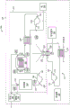
Fig. 2 is a block diagram of an underwater vehicle utilizing a stirling engine for heat recovery and temperature control of a SOFC in an exemplary embodiment.
Fig. 3 is a block diagram of a subsea vehicle utilizing a stirling engine for heat recovery and temperature control of a SOFC in an exemplary embodiment in an anode blower circuit.
Fig. 4 is a block diagram of a submerged vehicle utilizing a stirling engine for heat recovery and temperature control of a SOFC in an exemplary embodiment in a cathode blower circuit.
Fig. 5 is a flow chart of a method of controlling the temperature of an SOFC using a stirling engine in an exemplary embodiment.
Detailed Description
The figures and the following description illustrate specific exemplary embodiments. It will thus be appreciated that those skilled in the art will be able to devise various arrangements that, although not explicitly described or shown herein, embody the principles of the embodiments and are included within its scope. Moreover, any examples described herein are intended to aid in understanding the principles of the embodiments and are to be construed as being without limitation to such specifically recited examples and conditions. Therefore, the inventive concept is not limited to the specific embodiments or examples described below, but is defined by the claims and their equivalents.
Fig. 1 shows an underwater vehicle 100 that utilizes a stirling engine for heat recovery and temperature control of an SOFC in an exemplary embodiment. In this embodiment, the vehicle 100 is described as an unmanned submersible vehicle (UUV), but in other embodiments, the vehicle 100 may be any type of vehicle capable of being submerged and generating electricity using a SOFC fuel cell.
In this embodiment, the vehicle 100 is a submersible that utilizes an onboard energy source that allows the vehicle 100 to operate for a long period of time without floating out of the water. Typically, submersibles utilize nuclear energy sources or batteries to provide power to the vehicle. However, in this embodiment, the vehicle 100 utilizes an onboard fuel cell (e.g., SOFC) that is supplied with locally stored fuel (e.g., hydrocarbon fuel) and locally stored oxidant (e.g., oxygen) to allow for long periods of underwater mission without floating out of the water.
SOFCs generate a large amount of waste heat due to the exothermic oxidation of fuel within the SOFC, which is typically removed by transferring the waste heat into the water in which the vehicle is operating. Furthermore, SOFCs require cooling to prevent them from exceeding their maximum operating temperature. This cooling is typically performed by operating the cathode blower of the SOFC at a higher rate than is required for the SOFC's fuel oxidation rate. This increases additional power losses in the system and reduces efficiency. In the embodiments described herein, the vehicle 100 uses the SOFC in combination with a stirling engine to recover some of the waste heat generated by the SOFC while also controlling the temperature of the SOFC. This allows the cathode blower to run at a lower speed, which reduces system parasitic losses and improves efficiency. Also, in some embodiments, the stirling engine may use the recovered waste heat to rotate the generator head, which may increase the power generation through the SOFC. This allows the vehicle 100 to operate for long periods of time without refueling.
Fig. 2 is a block diagram 200 of the vehicle 100 utilizing a stirling engine 222 for heat recovery and temperature control of the SOFC202 in an exemplary embodiment. Block diagram 200 is a simplified representation of SOFC202 and several components to support the operation of SOFC202, and it should be understood by those skilled in the art that additional components not shown (e.g., valves, cooling circuits, blowers, etc.) may be used as a matter of design choice.
In this embodiment, fuel 246 is combined with oxygen 236 and oxidized within SOFC202 to generate electricity for vehicle 100. Although heavy hydrocarbon fuels may be used due to their high energy density, fuel 246 may include any type of hydrogen-based fuel as a matter of design choice (e.g., H)2). Some examples of heavy hydrocarbon fuels are alcohols, gasoline, diesel, and jet fuels. When using heavy hydrocarbon fuels, fuel reformer 240 is used to generate free H2For use in SOFC202, free H2May be provided to the anode side of the SOFC202 (e.g., through the anode inlet 208) by an anode blower 248. Unoxidized H2And water is discharged from SOFC202 (e.g., through anode outlet 210) and returned to reformer 240. Anode purge system 264 removes generated H2O and CO2。
FIG. 2 also shows a number of temperature sensors 254 and 260 that are used to monitor various temperatures inside the insulated box 201. Sensors 254-255 measure the temperature of the cathode inlet 204 and the cathode outlet 206 of the SOFC, respectively. Sensors 256 and 257 measure the temperature at anode inlet 208 and anode outlet 210, respectively, of SOFC 202. Sensors 258 and 259 respectively measure the temperature of inlet 242 and outlet 244 of reformer 240. The sensor 260 measures the temperature inside the heat insulation box 201.
In this embodiment, the stirling engine 222 is used to recover waste heat generated within the insulated cabinet 201 and provide temperature control of the SOFC202 and/or other components within the insulated cabinet 201. The Stirling engine 222 includes a hot end 224 and a cold end 226. The hot end 224 is thermally coupled to the inside of the heat insulation box 201 and absorbs radiant heat from the inside of the heat insulation box 201. The cold end 226 is thermally coupled to the cooling circuit 212. The temperature difference between the hot end 224 and the cold end 226 heats the working gas within the stirling engine 222 to drive one or more pistons (not shown) of the rotating shaft. During operation of the Stirling engine 222, heat flows from the hot end 224 to the cold end 226. This allows heat to be removed from the insulated box 201 at variable flow rates depending on the temperature difference between the hot 224 and cold 226 ends. In some embodiments, the stirling engine 222 is coupled to a generator head (generating head)262 that provides power to the vehicle 100 that is in addition to the power generated by the SOFC 202.
The cooling circuit 212 is used to dissipate heat from the cold end 226 of the stirling engine 222 and to provide a temperature differential between the hot end 224 and the cold end 226. In this embodiment, the cooling circuit 212 includes a cooling pump 216 having an outlet 220 coupled to a cold end 226 of a Stirling engine 222 and an inlet 218 coupled to a heat exchanger 214. The cooling pump 216 circulates a coolant (e.g., water, glycol, etc.) that circulates around the cooling circuit 212. The heat at the cold end 226 of the stirling engine 222 is transferred to the coolant in the cooling circuit 212 and then to the cooling water in the heat exchanger 214. The cooling water used by the heat exchanger 214 may be water in which the vehicle 100 is operating.
In this embodiment, the thermal management controller 228 includes any component, system, or device capable of monitoring the temperature inside the insulated cabinet 201 via the sensors 254 and 260 and controlling the temperature by varying the heat dissipation rate of the cold end 226 of the Stirling engine 222. To do so, the controller 228 varies a pump control signal applied to the cooling pump 216, thereby varying the flow rate of coolant within the cooling circuit 212. As the flow rate of the coolant increases, a greater thermal gradient is created between the hot end 224 and the cold end 226 of the stirling engine 222. This increases the speed of the Stirling engine 222 and increases the amount of thermal energy (e.g., electricity generation) that is converted into useful work. As the flow rate of the coolant decreases, a smaller thermal gradient is created between the hot end 224 and the cold end 226 of the stirling engine 222. This reduces the speed of the Stirling engine 222 and reduces the amount of thermal energy (e.g., electricity) that is converted into useful work. Using the stirling engine 222, the temperature of the SOFC202 and/or other components within the insulated cabinet 201 can be controlled. When the stirling engine 222 is utilized to control the temperature of the SOFC202, the cooling typically provided by the cathode blower 230 can be reduced, thereby reducing the power used by the cathode blower 230. This reduces the additional power that would normally be consumed by cathode blower 230.
The following examples are considered. In the first example, the temperature of the cathode outlet 206 of the SOFC202 is considered to rise slowly. During operation, SOFC202 oxidizes fuel 246 and generates heat. The SOFC202 radiates heat into the insulated cabinet 201 at a rate that is generally dependent on the temperature differential between the SOFC202 and the interior of the insulated cabinet 201. Thus, in some cases, the temperature difference may be reduced, thereby reducing the heat transfer rate from the SOFC202 to the inside of the insulation box 201. This causes the SOFC202 to heat up over time. This can be detected at the cathode outlet 206 using a temperature sensor 255 for control by the controller 228, which is a good proxy for the temperature of the SOFC 202. SOFC202, however, operates more efficiently over a particular temperature range. For example, it may be desirable to maintain the temperature of SOFC202 within about +/-100 degrees celsius of about 750 degrees celsius. If the temperature drops too low (e.g., about 600 degrees celsius), the ceramic electrolyte in the SOFC202 may not effectively transfer oxygen ions from the cathode to the anode. However, if the temperature rises too high (e.g., about 1000 degrees celsius), the SOFC202 may be damaged due to thermal stress.
A typical reaction to the heat generation of the SOFC202 towards the high end of the operating temperature over time is to increase the cathode flow rate of the SOFC 202. Controller 228 may increase the cathode flow rate of SOFC202 by varying the cathode blower signal applied to cathode blower 230. An increase in the cathode flow rate of the SOFC202 will remove heat from the SOFC202 at a faster rate because the oxygen at the outlet 234 of the cathode blower 230 is less than about 100 degrees celsius. This will reduce the temperature of the SOFC202 due to cooling. However, the cathode blower 230 will consume more power to increase the cathode flow rate, which is inefficient.
Instead of and/or in addition to increasing the cathode flow rate, the controller 228 varies a pump control signal applied to the cooling pump 216 to increase the flow rate of coolant within the cooling circuit 212. The increased coolant flow rate allows the stirling engine 222 to dissipate heat within the insulated cabinet 201 at a faster rate, which reduces the cooling requirements for the various components (e.g., SOFC 202) within the insulated cabinet 201. The heat consumed by the stirling engine 222 mitigates the amount of cooling that is provided instead by the cathode blower. Furthermore, the work performed by the stirling engine 222 may be used to generate electricity, more efficiently utilizing waste heat generated by the components within the SOFC202 and the insulated cabinet 201 than merely dumping the waste heat into the water surrounding the vehicle 100. In the next example, the temperature of the cathode outlet 206 of the SOFC202 is considered to be slowly decreasing. During operation, SOFC202 oxidizes fuel 246 and generates heat. The SOFC202 radiates heat into the insulated cabinet 201 at a rate that is generally dependent on the temperature differential between the SOFC202 and the interior of the insulated cabinet 201. Thus, in some cases, the temperature difference may be higher, thereby increasing the heat transfer rate from the SOFC202 to the interior of the insulation box 201. This cools the SOFC202 over time. This can be detected at the cathode outlet 206 using a temperature sensor 255 and controlled by the controller 228, which is a good proxy for the temperature of the SOFC 202.
A typical reaction to the SOFC202 cooling down to the low end of the operating temperature over time is to reduce the cathode flow rate of the SOFC202 towards some minimum flow rate, some of which depends on the oxidation rate of the fuel 246 at the SOFC 202. The controller 228 can reduce the cathode flow rate of the SOFC202 by varying the cathode blower signal applied to the cathode blower 230. Although the SOFC202 may still heat up even when the cathode flow rate of the SOFC202 is a minimum flow rate, the reduced cathode flow rate of the SOFC202 removes heat from the SOFC202 at a slower rate.
In this case, the controller 228 varies the pump control signal of the cooling pump 216 to decrease the flow rate of the coolant in the cooling circuit 212. The reduced coolant flow rate allows the stirling engine 222 to dissipate heat within the insulated box 201 at a slower rate, which allows the SOFC202 to heat up. Further, the work produced by the Stirling engine 222 during this process may be used to generate electricity, thereby increasing efficiency.
While the temperature control process performed by the controller 228 has been specifically described with respect to the temperature of the cathode outlet 206 of the SOFC202, there are other control points inside the insulated box 201. For example, instead of and/or in addition to the temperature of cathode outlet 206, controller 228 may vary the pump control signal applied to cooling pump 216 to control the temperature of inlet 242 of reformer 240 (via sensor 258), outlet 244 of reformer 240 (via sensor 259), the interior of insulated cabinet 201 (via sensor 260), cathode inlet 204 (via sensor 254), anode inlet 208 (via sensor 256), and/or anode outlet 210 (via sensor 257). For example, if the cathode blower 230 is at a minimum flow rate, then decreasing the temperature within the insulated cabinet 201 indicates that the Stirling engine 222 is consuming a significant amount of heat within the insulated cabinet 201. In this case, the pump control signal of the cooling pump 216 is changed to decrease the flow rate of the coolant in the cooling circuit 212.
Fig. 3 is a block diagram 300 of the vehicle 100 utilizing the stirling engine 222 in an anode blower circuit for heat recovery and temperature control of the SOFC202 in an exemplary embodiment. In this embodiment, the outlet 244 of the reformer 240 is routed to the hot end 224 of the stirling engine 222 and returned to the inlet 250 of the anode blower 248. This thermally couples the high temperature outlet 244 of the reformer 240 to the hot end 224 of the stirling engine. During operation, the Stirling engine 222 extracts heat from the reformed fuel exiting the reformer 240 and cools the reformed fuel before it enters the anode blower 248. The reformed fuel is typically cooled using a separate cooling loop. Thus, the Stirling engine 222 is able to recover waste heat from the reformed fuel that would normally be lost. Fig. 3 further illustrates the hot end 224 of the stirling engine 222 coupled to an anode purge system 264. This allows the Stirling engine 222 to extract waste heat from the anode purification system 264, which is typically dissipated. In addition to collecting radiant heat from the insulated box 201, heat extraction may be performed on the reformate and anode purge system 264.
Fig. 4 is a block diagram 400 of the vehicle 100 utilizing the stirling engine 222 in the cathode blower circuit for heat recovery and temperature control of the SOFC202 in an exemplary embodiment. In this embodiment, the outlet 234 of the cathode blower 230 is routed to the cold end 226 of the Stirling engine 222 and returned to the heat exchanger 238. This allows heat to be transferred from the hot end 224 of the stirling engine 222 to the oxygen provided to the cathode of the SOFC 202. The mixture is preheated before being transferred to heat exchanger 238, which is typically heated from less than about 100 degrees celsius to about 650 degrees celsius. This allows the cooling circuit of the stirling engine 222 to be used as part of a pre-heat treatment of the oxygen provided to the cathode of the SOFC 202. Although this embodiment illustrates the hot end 224 of the stirling engine 222 thermally coupled to the interior of the insulated cabinet 201 as a heat source, any of the heat sources previously described for the hot end 224 may additionally and/or alternatively be used as the subject of design choice.
With the stirling engine 222, waste heat that would normally be lost to the water in which the vehicle 100 is operating can be used for additional work. In addition, the stirling engine 222 operates as a variable heat sink, which allows the controller 228 to control the temperature within the insulated cabinet 201 by varying the flow rate of the cooling circuit 212. In some cases, this may allow cathode blower 230 to run at a reduced speed, thereby reducing additional electrical losses of vehicle 100.
Fig. 5 is a flow chart of a method 500 of controlling the temperature of an SOFC using a stirling engine in an exemplary embodiment. The steps of method 500 will be described with respect to controller 228 in fig. 2-4, but those skilled in the art will appreciate that method 500 described herein may be performed by other devices or systems not shown. The steps of method 500 are not all inclusive and may include other steps not shown. In step 502, the controller 228 monitors the temperature of the cathode outlet 206 of the SOFC202 (e.g., via the sensor 255). SOFC202 is surrounded by insulated box 201 and thermally coupled to hot end 224 of stirling engine 222. In step 504, the controller 228 varies the heat dissipation rate of the cold end 226 of the stirling engine (e.g., by varying the cooling applied to the cold end 226 by the cooling circuit 212, by varying the flow rate of the cathode blower 230, etc.) to maintain the temperature of the cathode outlet 26 of the SOFC202 within a temperature range.
Any of the various elements shown in the figures or described herein may be implemented in hardware, software, firmware, or some combination of these. For example, the elements may be implemented as dedicated hardware. A dedicated hardware element may be referred to as a "processor," "controller," or some similar terminology. When provided by a processor, the functions may be provided by a single dedicated processor, by a single shared processor, or by a plurality of individual processors, some of which may be shared. Moreover, explicit use of the term "processor" or "controller" should not be construed to refer exclusively to hardware capable of executing software, and may implicitly include, without limitation, Digital Signal Processor (DSP) hardware, network processor, Application Specific Integrated Circuit (ASIC) or other circuitry, Field Programmable Gate Array (FPGA), Read Only Memory (ROM) for storing software, Random Access Memory (RAM), non-transitory memory, logic, or some other physical hardware component or module.
Also, the elements may be implemented as instructions executable by a processor or a computer to perform the functions of the elements. Some examples of instructions are software, program code, and firmware. The instructions are operable, when executed by the processor, to direct the processor to perform the functions of the element. The instructions may be stored on a storage device readable by the processor. Some examples of storage devices are digital or solid state memory, magnetic storage media such as disks and tapes, hard drives, or optically readable digital data storage media.
Although specific embodiments have been described herein, the scope is not limited to those specific embodiments. Rather, the scope is defined by the appended claims and any equivalents thereof.
Claims (17)
1. An apparatus for heat recovery and thermal control of a solid oxide fuel cell in an underwater vehicle, the apparatus comprising a vehicle configured to be submerged,
the vehicle includes: a solid oxide fuel cell, the vehicle further comprising:
a thermal box surrounding the solid oxide fuel cell, wherein the solid oxide fuel cell comprises a cathode inlet, a cathode outlet, an anode inlet, and an anode outlet;
a cooling circuit of the vehicle comprising a heat exchanger and a cooling pump, wherein the heat exchanger thermally couples the cooling circuit to the water;
a Stirling engine having a first end thermally coupled to an interior of the heat shield case and a second end thermally coupled to the cooling circuit;
the cooling pump is configured to vary a heat dissipation rate of the second end of the Stirling engine based on a pump control signal;
a thermal management controller configured to monitor a temperature of the cathode outlet of the solid oxide fuel cell and to vary the pump control signal to maintain the temperature of the cathode outlet of the solid oxide fuel cell within a temperature range,
a generator head coupled to a power output shaft of the Stirling engine; and
a power bus for distributing power to the vehicle, wherein the solid oxide fuel cell and the generator head are electrically coupled to the power bus.
2. The apparatus of claim 1, further comprising:
a cathode blower having an outlet and an inlet, wherein the inlet of the cathode blower is coupled to the cathode outlet of the solid oxide fuel cell;
wherein the cathode blower is configured to vary a cooling rate provided to the solid oxide fuel cell based on a cathode blower control signal;
wherein the thermal management controller is configured to vary the pump control signal to increase a heat dissipation rate of the second end of the Stirling engine and to vary the cathode blower control signal to decrease a cooling rate provided to the solid oxide fuel cell in response to the heat dissipation rate of the second end of the Stirling engine increasing.
3. The apparatus of claim 2, further comprising:
an oxygen source coupled to the outlet of the cathode blower.
4. The apparatus of claim 1, wherein:
the thermal management controller is configured to monitor at least one of a temperature of the anode inlet of the solid oxide fuel cell and a temperature of the cathode inlet of the solid oxide fuel cell and to vary the pump control signal to maintain at least one of the temperature of the anode inlet of the solid oxide fuel cell and the temperature of the cathode inlet of the solid oxide fuel cell within a temperature range.
5. The apparatus of claim 1, wherein:
the thermal management controller is configured to monitor at least one of the temperature of the interior of the insulated cabinet and the temperature of the anode outlet of the solid oxide fuel cell and to vary the pump control signal to maintain at least one of the temperature of the interior of the insulated cabinet and the temperature of the anode outlet of the solid oxide fuel cell within a temperature range.
6. The apparatus of claim 1, further comprising:
a fuel source; and
a fuel reformer having an inlet and an outlet, wherein the inlet of the fuel reformer is coupled to the fuel source and the anode outlet of the solid oxide fuel cell;
an anode blower having an inlet and an outlet, wherein the outlet of the anode blower is coupled to the anode inlet of the solid oxide fuel cell, wherein the first end of the Stirling engine couples the outlet of the fuel reformer to the inlet of the anode blower.
7. The apparatus of claim 6, wherein:
the thermal management controller is configured to monitor at least one of a temperature of an inlet of the fuel reformer and a temperature of an outlet of the fuel reformer and to vary the pump control signal to maintain at least one of the temperature of the inlet of the fuel reformer and the temperature of the outlet of the fuel reformer within a temperature range.
8. The apparatus of claim 3, wherein:
the oxygen source stores an oxidant.
9. The apparatus of claim 1, wherein:
a first end of the stirling engine is coupled to the anode outlet of the solid oxide fuel cell.
10. An apparatus for heat recovery and thermal control of a solid oxide fuel cell in an underwater vehicle, the apparatus comprising a vehicle configured to be submerged,
the vehicle comprises a solid oxide fuel cell, the vehicle further comprising:
a thermal box surrounding the solid oxide fuel cell, wherein the solid oxide fuel cell comprises a cathode inlet, a cathode outlet, an anode inlet, and an anode outlet;
a cathode blower having an outlet and an inlet, wherein the inlet of the cathode blower is coupled to the cathode outlet of the solid oxide fuel cell, wherein the cathode blower is configured to vary a cooling rate provided to the solid oxide fuel cell based on a cathode blower control signal;
a Stirling engine having a first end thermally coupled to an interior of the heat shield box and a second end coupling an outlet of the cathode blower to the cathode inlet of the solid oxide fuel cell, wherein the cathode blower is configured to vary a heat dissipation rate of the Stirling engine second end based on the cathode blower control signal; and
a thermal management controller configured to monitor a temperature of the cathode outlet of the solid oxide fuel cell and to vary the cathode blower control signal to maintain the temperature of the cathode outlet of the solid oxide fuel cell within a temperature range,
a generator head coupled to a power output shaft of the Stirling engine; and
a power bus for distributing power to the vehicle, wherein the solid oxide fuel cell and the generator head are electrically coupled to the power bus.
11. The apparatus of claim 10, further comprising:
an oxygen source coupled to an outlet of the cathode blower.
12. The apparatus of claim 11, wherein:
the oxygen source stores an oxidant.
13. The apparatus of claim 10, wherein:
the thermal management controller is configured to monitor at least one of a temperature of the anode inlet of the solid oxide fuel cell and a temperature of the cathode inlet of the solid oxide fuel cell and to vary the cathode blower control signal to maintain at least one of the temperature of the anode inlet of the solid oxide fuel cell and the temperature of the cathode inlet of the solid oxide fuel cell within a temperature range.
14. The apparatus of claim 10, wherein:
the thermal management controller is configured to monitor at least one of the temperature of the interior of the insulated cabinet and the temperature of the anode outlet of the solid oxide fuel cell and to vary the cathode blower control signal to maintain at least one of the temperature of the interior of the insulated cabinet and the temperature of the anode outlet of the solid oxide fuel cell within a temperature range.
15. The apparatus of claim 10, wherein:
a first end of the stirling engine is coupled to the anode outlet of the solid oxide fuel cell.
16. The apparatus of claim 10, further comprising:
a fuel source;
a fuel reformer having an inlet and an outlet, wherein the inlet of the fuel reformer is coupled to the fuel source and the anode outlet of the solid oxide fuel cell; and
an anode blower having an inlet and an outlet, wherein the outlet of the anode blower is coupled to the anode inlet of the solid oxide fuel cell, wherein the first end of the Stirling engine couples the outlet of the fuel reformer to the inlet of the anode blower.
17. The apparatus of claim 16, wherein:
the thermal management controller is configured to monitor at least one of a temperature of an inlet of the fuel reformer and a temperature of an outlet of the fuel reformer and to vary the cathode blower control signal to maintain at least one of the temperature of the inlet of the fuel reformer and the temperature of the outlet of the fuel reformer within a temperature range.
Applications Claiming Priority (2)
| Application Number | Priority Date | Filing Date | Title |
|---|---|---|---|
| US14/319,091 US9716284B2 (en) | 2014-06-30 | 2014-06-30 | Heat reclamation and temperature control for submersible vehicles that utilize fuel cells |
| US14/319,091 | 2014-06-30 |
Publications (2)
| Publication Number | Publication Date |
|---|---|
| CN105226314A CN105226314A (en) | 2016-01-06 |
| CN105226314B true CN105226314B (en) | 2020-07-07 |
Family
ID=53483749
Family Applications (1)
| Application Number | Title | Priority Date | Filing Date |
|---|---|---|---|
| CN201510379060.3A Active CN105226314B (en) | 2014-06-30 | 2015-06-30 | Heat recovery and temperature control for underwater vehicles utilizing fuel cells |
Country Status (6)
| Country | Link |
|---|---|
| US (1) | US9716284B2 (en) |
| EP (1) | EP2975683B1 (en) |
| JP (2) | JP6532733B2 (en) |
| CN (1) | CN105226314B (en) |
| BR (1) | BR102015011276B1 (en) |
| NO (1) | NO3136728T3 (en) |
Families Citing this family (10)
| Publication number | Priority date | Publication date | Assignee | Title |
|---|---|---|---|---|
| US9742196B1 (en) * | 2016-02-24 | 2017-08-22 | Doosan Fuel Cell America, Inc. | Fuel cell power plant cooling network integrated with a thermal hydraulic engine |
| EP3538430B1 (en) * | 2016-11-10 | 2022-01-12 | Cappelletti, Sergio | Ventilation system |
| CN108071477B (en) * | 2016-11-11 | 2019-05-28 | 中国科学院沈阳自动化研究所 | A kind of ocean robot cooling water control system and method |
| CN112644672A (en) * | 2018-08-13 | 2021-04-13 | 东莞市凯勒帝数控科技有限公司 | Underwater bionic robot propelling device with damping function |
| US11465766B2 (en) * | 2019-06-28 | 2022-10-11 | The Boeing Company | Systems and methods for cooling and generating power on high speed flight vehicles |
| US10781771B1 (en) * | 2019-09-22 | 2020-09-22 | Ghasem Kahe | Automatic cooling system for combustion engine |
| JP7481168B2 (en) * | 2020-06-04 | 2024-05-10 | 株式会社豊田自動織機 | Fuel cell pump |
| CN111846167B (en) * | 2020-07-29 | 2021-11-02 | 青岛海研电子有限公司 | Seabed-based monitoring system |
| EP4001599B8 (en) | 2020-11-23 | 2023-04-12 | The Boeing Company | Methods and systems for generating power and thermal management having combined cycle architecture |
| CN113157016B (en) * | 2021-03-23 | 2022-08-23 | 北京无线电计量测试研究所 | Incubator for atomic clock and use method |
Citations (6)
| Publication number | Priority date | Publication date | Assignee | Title |
|---|---|---|---|---|
| CA2394924A1 (en) * | 2000-10-30 | 2002-05-10 | Questair Technologies Inc. | Energy efficient gas separation for fuel cells |
| CN1516310A (en) * | 2002-12-23 | 2004-07-28 | ͨ�õ�����˾ | Integrated fuel cell mixed power plant with recirculating air and fuel flow |
| JP2010174686A (en) * | 2009-01-28 | 2010-08-12 | Kyocera Corp | Composite power generation device |
| CN102468505A (en) * | 2010-11-17 | 2012-05-23 | 现代自动车株式会社 | Method for controlling temperature of fuel cell system |
| CN102975836A (en) * | 2012-12-18 | 2013-03-20 | 天津大学 | Underwater glider energy source system and control method thereof |
| CN103119770A (en) * | 2010-09-30 | 2013-05-22 | Toto株式会社 | Solid oxide fuel cell device |
Family Cites Families (11)
| Publication number | Priority date | Publication date | Assignee | Title |
|---|---|---|---|---|
| JP2526330Y2 (en) * | 1991-04-01 | 1997-02-19 | 三菱重工業株式会社 | Power source for underwater vehicles |
| JPH11214021A (en) * | 1998-01-27 | 1999-08-06 | Ishikawajima Harima Heavy Ind Co Ltd | Solid electrolyte type fuel cell power generating apparatus |
| DE10045899A1 (en) * | 2000-09-16 | 2002-04-25 | Forschungszentrum Juelich Gmbh | Device and method for generating electricity |
| JP2004512665A (en) * | 2000-10-30 | 2004-04-22 | クエストエアー テクノロジーズ インコーポレイテッド | Energy efficient gas separation for fuel cells |
| JP2002266702A (en) * | 2001-03-12 | 2002-09-18 | Honda Motor Co Ltd | Composite energy generating device |
| JP3897149B2 (en) * | 2001-08-23 | 2007-03-22 | 独立行政法人産業技術総合研究所 | Solid oxide fuel cell and Stirling engine combined system |
| JP3917838B2 (en) * | 2001-10-12 | 2007-05-23 | 三菱重工業株式会社 | Fuel cell system and combined power generation system |
| JP2006032262A (en) * | 2004-07-21 | 2006-02-02 | Tokyo Gas Co Ltd | Fuel cell system and control method |
| US20060168951A1 (en) * | 2005-01-31 | 2006-08-03 | Caterpillar Inc. | Regeneration management system for a work machine |
| JP2008051062A (en) * | 2006-08-28 | 2008-03-06 | Hitachi Ltd | Automobile |
| WO2010027726A1 (en) * | 2008-08-27 | 2010-03-11 | Alliant Techsystems Inc. | Methods and systems of producing hydrogen and oxygen for power generation, and power source |
-
2012
- 2012-06-27 NO NO16192028A patent/NO3136728T3/no unknown
-
2014
- 2014-06-30 US US14/319,091 patent/US9716284B2/en active Active
-
2015
- 2015-03-31 JP JP2015071341A patent/JP6532733B2/en active Active
- 2015-05-15 BR BR102015011276-9A patent/BR102015011276B1/en active IP Right Grant
- 2015-06-30 EP EP15174482.8A patent/EP2975683B1/en active Active
- 2015-06-30 CN CN201510379060.3A patent/CN105226314B/en active Active
-
2019
- 2019-04-01 JP JP2019069781A patent/JP6782808B2/en active Active
Patent Citations (6)
| Publication number | Priority date | Publication date | Assignee | Title |
|---|---|---|---|---|
| CA2394924A1 (en) * | 2000-10-30 | 2002-05-10 | Questair Technologies Inc. | Energy efficient gas separation for fuel cells |
| CN1516310A (en) * | 2002-12-23 | 2004-07-28 | ͨ�õ�����˾ | Integrated fuel cell mixed power plant with recirculating air and fuel flow |
| JP2010174686A (en) * | 2009-01-28 | 2010-08-12 | Kyocera Corp | Composite power generation device |
| CN103119770A (en) * | 2010-09-30 | 2013-05-22 | Toto株式会社 | Solid oxide fuel cell device |
| CN102468505A (en) * | 2010-11-17 | 2012-05-23 | 现代自动车株式会社 | Method for controlling temperature of fuel cell system |
| CN102975836A (en) * | 2012-12-18 | 2013-03-20 | 天津大学 | Underwater glider energy source system and control method thereof |
Also Published As
| Publication number | Publication date |
|---|---|
| JP6782808B2 (en) | 2020-11-11 |
| EP2975683A1 (en) | 2016-01-20 |
| EP2975683B1 (en) | 2017-08-16 |
| CN105226314A (en) | 2016-01-06 |
| JP2019114556A (en) | 2019-07-11 |
| JP2016015309A (en) | 2016-01-28 |
| NO3136728T3 (en) | 2018-07-28 |
| US9716284B2 (en) | 2017-07-25 |
| US20150380748A1 (en) | 2015-12-31 |
| JP6532733B2 (en) | 2019-06-19 |
| BR102015011276A2 (en) | 2016-06-14 |
| BR102015011276B1 (en) | 2022-06-07 |
Similar Documents
| Publication | Publication Date | Title |
|---|---|---|
| CN105226314B (en) | Heat recovery and temperature control for underwater vehicles utilizing fuel cells | |
| US20170133731A1 (en) | Battery system with selective thermal management | |
| CN108666700B (en) | Closed-loop direct cooling system for sealed high-voltage traction battery pack | |
| US20180114998A1 (en) | Thermal management system for fuel cell vehicle and control method thereof | |
| JP2007091035A (en) | Automobile driving system and automobile | |
| JP2006024418A (en) | Fuel cell system | |
| JP2009227115A (en) | Mobile body for transporting automobile | |
| CN110165245B (en) | Fuel cell thermal management method and system based on semiconductor material and phase-change material | |
| US10026982B2 (en) | Condensate recovery for reversible solid oxide fuel cells | |
| US20130276849A1 (en) | Teg-powered cooling circuit for thermoelectric generator | |
| US20230090996A1 (en) | Systems and methods for controlling a cooling system of a vehicle | |
| JP2007134241A (en) | Fuel cell cooling system | |
| CN105336970A (en) | Fuel cell system and method for controlling the same | |
| CN113903945B (en) | Power generation system and method for operating a power generation system | |
| CN113690460A (en) | Fuel cell thermoelectric exchange cold start preheating and waste heat energy recovery system and method | |
| JP2005353327A (en) | Electric automobile | |
| JP4984546B2 (en) | Fuel cell system | |
| JP2010021061A (en) | Fuel cell power generation system | |
| WO2019031992A1 (en) | System and method of emergency cooling of nuclear reactor | |
| KR101987502B1 (en) | Surplus Electric Energy Reductor for Fuel Cell Vehicle | |
| RU2584248C2 (en) | Electric power generator on fuel elements and control method thereof | |
| JP2019160522A (en) | Energy supply system and energy supply method | |
| KR20190029015A (en) | Controlling method of fuel cell vehicle | |
| JP2005078982A (en) | Power generation system | |
| JP2009170220A (en) | Fuel cell mounted vehicle |
Legal Events
| Date | Code | Title | Description |
|---|---|---|---|
| C06 | Publication | ||
| PB01 | Publication | ||
| SE01 | Entry into force of request for substantive examination | ||
| SE01 | Entry into force of request for substantive examination | ||
| GR01 | Patent grant | ||
| GR01 | Patent grant |