CN105143990B - Developer supply container - Google Patents
Developer supply container Download PDFInfo
- Publication number
- CN105143990B CN105143990B CN201380075849.9A CN201380075849A CN105143990B CN 105143990 B CN105143990 B CN 105143990B CN 201380075849 A CN201380075849 A CN 201380075849A CN 105143990 B CN105143990 B CN 105143990B
- Authority
- CN
- China
- Prior art keywords
- developer
- discharge
- regulating
- replenishment container
- fluid communication
- Prior art date
- Legal status (The legal status is an assumption and is not a legal conclusion. Google has not performed a legal analysis and makes no representation as to the accuracy of the status listed.)
- Active
Links
- 230000001105 regulatory effect Effects 0.000 claims abstract description 127
- 238000007599 discharging Methods 0.000 claims abstract description 38
- 238000004891 communication Methods 0.000 claims description 114
- 239000012530 fluid Substances 0.000 claims description 110
- 230000007246 mechanism Effects 0.000 description 50
- 230000036961 partial effect Effects 0.000 description 48
- 239000000843 powder Substances 0.000 description 28
- 238000006243 chemical reaction Methods 0.000 description 24
- 239000000463 material Substances 0.000 description 22
- 230000008859 change Effects 0.000 description 21
- 230000002829 reductive effect Effects 0.000 description 16
- 238000012986 modification Methods 0.000 description 15
- 230000004048 modification Effects 0.000 description 15
- 239000002245 particle Substances 0.000 description 11
- 230000005484 gravity Effects 0.000 description 10
- 238000012360 testing method Methods 0.000 description 10
- 230000006835 compression Effects 0.000 description 8
- 238000007906 compression Methods 0.000 description 8
- 230000008602 contraction Effects 0.000 description 8
- 230000000052 comparative effect Effects 0.000 description 7
- 238000000034 method Methods 0.000 description 7
- 238000010586 diagram Methods 0.000 description 6
- 229920005989 resin Polymers 0.000 description 6
- 239000011347 resin Substances 0.000 description 6
- 238000012795 verification Methods 0.000 description 6
- 230000000694 effects Effects 0.000 description 5
- 238000010200 validation analysis Methods 0.000 description 5
- XECAHXYUAAWDEL-UHFFFAOYSA-N acrylonitrile butadiene styrene Chemical compound C=CC=C.C=CC#N.C=CC1=CC=CC=C1 XECAHXYUAAWDEL-UHFFFAOYSA-N 0.000 description 4
- 229920000122 acrylonitrile butadiene styrene Polymers 0.000 description 4
- 239000004676 acrylonitrile butadiene styrene Substances 0.000 description 4
- 230000007613 environmental effect Effects 0.000 description 4
- 238000005259 measurement Methods 0.000 description 4
- 230000003287 optical effect Effects 0.000 description 4
- -1 polypropylene Polymers 0.000 description 4
- 230000008569 process Effects 0.000 description 4
- 230000000452 restraining effect Effects 0.000 description 4
- 238000003756 stirring Methods 0.000 description 4
- 238000011109 contamination Methods 0.000 description 3
- 230000007423 decrease Effects 0.000 description 3
- 239000002184 metal Substances 0.000 description 3
- 229910052751 metal Inorganic materials 0.000 description 3
- 230000002265 prevention Effects 0.000 description 3
- 230000009467 reduction Effects 0.000 description 3
- 230000002441 reversible effect Effects 0.000 description 3
- 238000000926 separation method Methods 0.000 description 3
- 239000004698 Polyethylene Substances 0.000 description 2
- 239000004743 Polypropylene Substances 0.000 description 2
- 238000013019 agitation Methods 0.000 description 2
- 238000004458 analytical method Methods 0.000 description 2
- 238000000071 blow moulding Methods 0.000 description 2
- 238000004140 cleaning Methods 0.000 description 2
- 229920006026 co-polymeric resin Polymers 0.000 description 2
- 239000000470 constituent Substances 0.000 description 2
- 238000000151 deposition Methods 0.000 description 2
- 238000001514 detection method Methods 0.000 description 2
- 238000011161 development Methods 0.000 description 2
- 238000006073 displacement reaction Methods 0.000 description 2
- 238000001746 injection moulding Methods 0.000 description 2
- 229920000728 polyester Polymers 0.000 description 2
- 229920000573 polyethylene Polymers 0.000 description 2
- 229920001155 polypropylene Polymers 0.000 description 2
- 238000007789 sealing Methods 0.000 description 2
- 238000003860 storage Methods 0.000 description 2
- 238000012546 transfer Methods 0.000 description 2
- 239000004793 Polystyrene Substances 0.000 description 1
- 230000004308 accommodation Effects 0.000 description 1
- 230000015572 biosynthetic process Effects 0.000 description 1
- 239000011362 coarse particle Substances 0.000 description 1
- 230000001276 controlling effect Effects 0.000 description 1
- 230000008878 coupling Effects 0.000 description 1
- 238000010168 coupling process Methods 0.000 description 1
- 238000005859 coupling reaction Methods 0.000 description 1
- 230000003247 decreasing effect Effects 0.000 description 1
- 230000008021 deposition Effects 0.000 description 1
- 238000005516 engineering process Methods 0.000 description 1
- 238000002474 experimental method Methods 0.000 description 1
- 239000010419 fine particle Substances 0.000 description 1
- 238000005243 fluidization Methods 0.000 description 1
- 239000011521 glass Substances 0.000 description 1
- 230000002401 inhibitory effect Effects 0.000 description 1
- 238000003780 insertion Methods 0.000 description 1
- 230000037431 insertion Effects 0.000 description 1
- 238000009434 installation Methods 0.000 description 1
- 239000004973 liquid crystal related substance Substances 0.000 description 1
- 238000004519 manufacturing process Methods 0.000 description 1
- 238000000691 measurement method Methods 0.000 description 1
- 150000002739 metals Chemical class 0.000 description 1
- 239000000203 mixture Substances 0.000 description 1
- 230000035515 penetration Effects 0.000 description 1
- 230000002093 peripheral effect Effects 0.000 description 1
- 229920002223 polystyrene Polymers 0.000 description 1
- 229920005990 polystyrene resin Polymers 0.000 description 1
- 230000001681 protective effect Effects 0.000 description 1
- 230000004044 response Effects 0.000 description 1
- 230000003068 static effect Effects 0.000 description 1
Images


Classifications
-
- G—PHYSICS
- G03—PHOTOGRAPHY; CINEMATOGRAPHY; ANALOGOUS TECHNIQUES USING WAVES OTHER THAN OPTICAL WAVES; ELECTROGRAPHY; HOLOGRAPHY
- G03G—ELECTROGRAPHY; ELECTROPHOTOGRAPHY; MAGNETOGRAPHY
- G03G15/00—Apparatus for electrographic processes using a charge pattern
- G03G15/06—Apparatus for electrographic processes using a charge pattern for developing
- G03G15/08—Apparatus for electrographic processes using a charge pattern for developing using a solid developer, e.g. powder developer
- G03G15/0822—Arrangements for preparing, mixing, supplying or dispensing developer
- G03G15/0865—Arrangements for supplying new developer
- G03G15/0867—Arrangements for supplying new developer cylindrical developer cartridges, e.g. toner bottles for the developer replenishing opening
- G03G15/087—Developer cartridges having a longitudinal rotational axis, around which at least one part is rotated when mounting or using the cartridge
- G03G15/0872—Developer cartridges having a longitudinal rotational axis, around which at least one part is rotated when mounting or using the cartridge the developer cartridges being generally horizontally mounted parallel to its longitudinal rotational axis
-
- G—PHYSICS
- G03—PHOTOGRAPHY; CINEMATOGRAPHY; ANALOGOUS TECHNIQUES USING WAVES OTHER THAN OPTICAL WAVES; ELECTROGRAPHY; HOLOGRAPHY
- G03G—ELECTROGRAPHY; ELECTROPHOTOGRAPHY; MAGNETOGRAPHY
- G03G15/00—Apparatus for electrographic processes using a charge pattern
- G03G15/06—Apparatus for electrographic processes using a charge pattern for developing
- G03G15/08—Apparatus for electrographic processes using a charge pattern for developing using a solid developer, e.g. powder developer
- G03G15/0822—Arrangements for preparing, mixing, supplying or dispensing developer
- G03G15/0877—Arrangements for metering and dispensing developer from a developer cartridge into the development unit
- G03G15/0881—Sealing of developer cartridges
- G03G15/0886—Sealing of developer cartridges by mechanical means, e.g. shutter, plug
Landscapes
- Physics & Mathematics (AREA)
- General Physics & Mathematics (AREA)
- Dry Development In Electrophotography (AREA)
- Wet Developing In Electrophotography (AREA)
Abstract
A developer replenishment container (1) detachably mountable to a developer replenishment apparatus (201) includes a developer accommodating unit (2) capable of accommodating a developer, a discharge opening (4a) for discharging the developer accommodated in the developer accommodating unit (2) toward the developer replenishment apparatus (201), a pump unit (3a) operating so that a discharge action occurs through the discharge opening (4a), a communicating portion (4d) provided at a position contacting the discharge opening (4a) and capable of holding a fixed amount of the developer, and a regulating unit (7) taking a developer inflow regulating state in which an inflow of the developer is regulated and a developer inflow non-regulating state in which the inflow of the developer is not regulated with respect to the communicating unit (4d), the regulating unit (7) being in the developer flow regulating state in a discharge operation by the pump unit (3 a). the regulating unit (7) includes an air flow path (7g) capable of connecting the communicating portion (4d) and the pump unit (3 a).
Description
Technical Field
The present invention relates to developer supply containers detachably mountable to a developer supply apparatus, the developer supply containers are used with an image forming apparatus (such as a copying machine, a facsimile machine, a printer, or a complex machine having the functions of a plurality of such machines) .
Background
Generally, an image forming apparatus such as an electrophotographic copying machine uses a developer in fine particles. In such an image forming apparatus, the developer is supplied from the developer replenishment container in response to the consumption of the developer due to the image forming operation.
Such a developer supply container is disclosed, for example, in japanese laid-open patent application 2010-256894.
The apparatus disclosed in japanese laid-open patent application 2010-256894 employs a system in which developer is discharged using a bellows pump provided in a developer replenishment container. More specifically, the bellows pump expands to provide a pressure lower than the ambient pressure in the developer replenishment container, so that air is drawn into the developer replenishment container to fluidize the developer. In addition, the bellows pump contracts to provide a pressure higher than the ambient pressure in the developer replenishment container, so that the developer is pushed out by a pressure difference between the inside and the outside of the developer replenishment container, thereby discharging the developer. By alternately repeating these two steps, the developer is stably discharged.
Disclosure of Invention
[ problem to be solved by the invention ]
As described above, with the apparatus disclosed in japanese laid-open patent application 2010-256894, the developer can be stably discharged out of the developer replenishment container, but the developer replenishment container requires higher supply accuracy for more stable image formation by the image forming apparatus.
Therefore, objects of the present invention are to provide kinds of developer replenishment containers with which the developer supply accuracy from the developer replenishment container to the image forming apparatus is higher.
[ means for solving problems ]
The present invention provides kinds of developer replenishment containers detachably mountable to a developer replenishment apparatus, the developer replenishment container including a developer accommodating portion capable of accommodating a developer, a discharge opening for discharging the developer accommodated in the developer accommodating portion from the developer replenishment container, a fluid communicating path extending from an inside of the developer replenishment container to the discharge opening, a pump portion having a volume that changes with a reciprocating movement and being at least operable on the discharge opening, a regulating portion for regulating a flow rate of the developer flowing into an entry region of the penetration path formed in an inner surface of the developer replenishment container, a movable portion for achieving a purpose that the regulating portion moves to the entry region and the regulating portion is retracted from the entry region, and an air flow path provided inside the regulating portion for bringing the discharge opening and at least the pump portion into fluid communication.
[ Effect of the invention ]
According to the present invention, it is possible to discharge developer from a developer replenishment container with high supply accuracy, and therefore it is possible to provide a developer replenishment container having more stable discharge performance for an image forming apparatus.
Drawings
Fig. 1 is a sectional view illustrating an overall arrangement of an image forming apparatus;
fig. 2 is a partial sectional view of the developer replenishment apparatus, with fig. (b) being a perspective view of the mounting portion and fig. (c) being a sectional view of the mounting portion;
fig. 3 is an enlarged sectional view illustrating a developer replenishment container and a developer replenishment apparatus;
fig. 4 is a flowchart of a flow of the developer supply operation;
fig. 5 is an enlarged sectional view of a modified example of the developer replenishment apparatus;
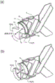
fig. 6 is a partial view (a) illustrating a developer replenishment container according to embodiment 1 of the present invention, a partial view (b) being a partially enlarged view illustrating a state around a discharge opening, and a partial view (c) being a front view illustrating a state in which the developer replenishment container is mounted to a mounting portion of the developer replenishment apparatus;
fig. 7 is a sectional perspective view of the developer replenishment container in fig. 7, in which fig. (a) is a partial sectional view of a state in which the pump portion is expanded to the maximum usable limit, and fig. (c) is a partial sectional view of a state in which the pump portion is contracted to the maximum usable limit;
fig. 8 is a partial view (a) of a vane used with the device for measuring flow energy, and a partial view (b) of the device;
fig. 9 is a graph showing the relationship between the diameter of the discharge opening and the discharge amount;
FIG. 10 is a graph showing the relationship between the amount in the container and the discharge amount;
fig. 11 is a partial view of a state in which the pump section is expanded to the maximum usable limit, (b) a partial view of a state in which the pump section is contracted to the maximum usable limit, and (c) a partial view of the pump section;
fig. 12 is an expanded front view illustrating a cam groove configuration of the developer replenishment container;
fig. 13 illustrates a change in the internal pressure of the developer replenishment container;
fig. 14 is an expanded front view of examples of the cam groove configuration of the developer replenishment container;
fig. 15 is an expanded front view of examples of the cam groove configuration of the developer replenishment container.
Fig. 16 is an expanded front view of examples of the cam groove configuration of the developer replenishment container;
fig. 17 is an expanded front view of examples of the cam groove configuration of the developer replenishment container;
fig. 18 is an expanded front view of examples of the cam groove configuration of the developer replenishment container;
fig. 19 is a partial view (a) of a perspective view of the entire feeding member according to embodiment 1 of the present invention, and a partial view (b) of a side view of the feeding member;
fig. 20 is a sectional view of a discharge portion of the pump portion in an operation stop stroke in embodiment 1;
fig. 21 is a sectional view of the discharge portion in the suction operation in embodiment 1;
fig. 22 is a sectional view of the drain portion in the drain operation in embodiment 1;
FIG. 23 is a sectional view of a discharging portion after other developers are discharged in embodiment 1;
fig. 24 is a sectional perspective view of a developer replenishment container according to a comparative example;
fig. 25 is a sectional perspective view of a modification of embodiment 1;
fig. 26 is a partially exploded perspective view of a portion of the cross section of a developer replenishment container according to embodiment 2 of the invention;
fig. 27 is a partial exploded perspective view of the entire feeding member in embodiment 2, and fig. 27 is a partial exploded perspective view of the feeding member;
the partial views (a) and (b) of fig. 28 are sectional views of the discharge portion in discharge in embodiment 2.
Detailed Description
Hereinafter, the developer replenishment container and the developer supply system according to the present invention will be described in detail. In the following description, unless otherwise specified, other known structures having similar functions may be substituted for the respective structures of the developer replenishment container within the scope of the concept of the present invention. In other words, unless otherwise specified, the present invention is not limited to the specific structures of the embodiments to be described below.
(example 1)
First, a basic structure of the image forming apparatus will be described, and subsequently, a developer supply system, that is, a developer replenishment apparatus and a developer replenishment container applied to the image forming apparatus will be described.
(image forming apparatus)
Referring to fig. 1, a structure of a copying machine (electrophotographic image forming apparatus) to which an electrophotographic type process is applied will be described as an example of an image forming apparatus using a developer replenishment apparatus to which a developer replenishment container (so-called toner cartridge) is detachably mountable.
In the drawings, a main assembly of a copying machine (a main assembly of an image forming apparatus or a main assembly of an apparatus) is denoted by reference numeral 100. An original document, which is placed on an original document support platen glass 102, is denoted by reference numeral 101. An optical image corresponding to image information of the original is imaged on an electrophotographic photosensitive member 104 (photosensitive member) by a lens Ln and a plurality of mirrors M of the optical portion 103, so that an electrostatic latent image is formed. The electrostatic latent image is made visible by a dry type developing device (one-component developing device) 201a with a toner (one-component magnetic toner) as a developer (dry powder).
In this embodiment, a one-component magnetic toner is used as the developer to be supplied from the developer replenishment container 1, but the present invention is not limited to this example but includes other examples that will be described below.
Specifically, in the case of employing a one-component developing device using a one-component non-magnetic toner, the one-component non-magnetic toner is supplied as a developer. In addition, in the case of employing a two-component developing device using a two-component developer containing a mixed magnetic carrier and a non-magnetic toner, the non-magnetic toner is supplied as the developer. In this case, both the non-magnetic toner and the magnetic carrier may be supplied as the developer.
Reference numerals 105 to 108 denote cassettes which contain recording materials (sheets) S. The optimum cassette of the sheets S stacked in the cassettes 105 to 108 is selected according to the sheet specification of the original 101 or information input by an operator (user) from a liquid crystal operation portion of the copying machine. The recording material is not limited to a paper sheet, but an OHP sheet or another material may also be used as needed.
sheets S fed by the separation and feed devices 105A to 108A are fed to the registration roller 110 along the feed portion 109 and are fed in synchronization with the rotation of the photosensitive member 104 and with the scanning of the optical portion 103.
Reference numerals 111, 112 denote a transfer charger and a separation charger. The image of the developer formed on the photosensitive member 104 is transferred onto the sheet S by the transfer charger 111. Then, the separation charger 112 separates the sheet S bearing the developed image (toner image) transferred thereon from the photosensitive member 104.
Thereafter, the sheet S fed by the feeding portion 113 is subjected to heat and pressure in the fixing portion 114, so that the developed image on the sheet is fixed, and then the sheet S passes through the discharging/reversing portion 115 in the one-sided copy mode, and then the sheet S is discharged to the discharge tray 117 by the discharge roller 116.
In the case of the double-sided copy mode, the sheet S enters the discharge/reverse portion 115 and its portion is discharged outside the apparatus by the discharge roller 116 degrees the trailing end of the sheet passes through the flapper 118, and the flapper 118 is controlled while the discharge roller 116 is still nipping the sheet S, the discharge roller 116 is rotated reversely so that the sheet S is fed into the apparatus again, then the sheet S is fed to the registration roller 110 by the refeeding portions 119, 120, and then conveyed along a path similar to that in the case of the single-sided copy mode and discharged to the discharge tray 117.
In the main assembly of the apparatus 100, image forming process equipment (process facilities) such as a developing device 201a as a developing facility, a cleaner portion 202 as a cleaning facility, and times of chargers 203 as charging facilities are provided around the photosensitive member 104. the developing device 201a develops an electrostatic latent image formed on the photosensitive member 104 by the optical portion 103 according to image information of 101 by depositing developer (toner) on the latent image.
The -time charger 203 is used to uniformly charge the surface of the photosensitive member 104 so that a desired electrostatic latent image is formed on the photosensitive member 104. in addition, the cleaning portion 202 removes the developer remaining on the photosensitive member 104.
(developer supply apparatus)
Referring to fig. 1 to 4, a developer replenishment apparatus 201 will be described, the developer replenishment apparatus 201 being a constituent element of a developer supply system. Fig. 2 is a partial sectional view of the developer replenishment apparatus, fig. 2 (a) is a perspective view of the mounting portion, and fig. (c) is a sectional view of the mounting portion.
Fig. 3 is a partially enlarged sectional view of the control system, the developer replenishment container 1, and the developer replenishment apparatus 201. Fig. 4 is a flowchart showing the developer supply operation implemented by the control system.
As shown in fig. 1, the developer replenishment apparatus 201 includes: a mounting portion (mounting space) 10 to which the developer replenishment container 1 is detachably mounted; a hopper 10a for temporarily storing the developer discharged from the developer replenishment container 1; and a developing device 201 a. As shown in a partial view (c) in fig. 2, the developer replenishment container 1 can be mounted to the mounting portion 10 in a direction indicated by an arrow M. Therefore, the longitudinal direction (rotational axis direction) of the developer replenishment container 1 is substantially the same as the direction of the arrow M. The direction of the arrow M is substantially parallel to the direction indicated by X of the partial diagram (b) of fig. 7 which will be described later. In addition, the direction of removal of the developer replenishment container 1 from the mounting portion 10 is opposite to the direction of arrow M (insertion direction).
As shown in fig. 1 and a partial view (a) of fig. 2, the developing device 201a includes a developing roller 201f, an agitating member 201c, and supplying members 201d and 201 e. The developer supplied from the developer replenishment container 1 is agitated by the agitating member 201c, supplied to the developing roller 201f by the magnet roller 201d and the supply member 201e, and supplied to the photosensitive member 104 by the developing roller 201 f.
A developing blade 201g for regulating the amount of developer overlaid on the roller is provided with respect to the developing roller 201f, and a leakage-preventive sheet 201h is provided to contact the developing roller 201f in order to prevent the developer from leaking between the developing device 201a and the developing roller 201 f.
As shown in fig. 2 (b), the mounting portion 10 is provided with a rotation regulating portion (holding mechanism) 11 for regulating the movement of the flange portion 4 in the rotational movement direction by abutting against the flange portion 4 (fig. 6) of the developer replenishment container 1 when the developer replenishment container 1 is mounted.
In addition, the mounting portion 10 is provided with a developer receiving opening (developer receiving hole) 13 for receiving the developer discharged from the developer replenishment container 1, and the developer receiving opening is in fluid communication with a discharge opening (discharge hole) 4a (fig. 6) of the developer replenishment container 1, which will be described later, when the developer replenishment container 1 is mounted on the mounting portion. The developer is supplied from the discharge opening 4a of the developer replenishment container 1 to the developing device 201a through the developer receiving opening 13. In this embodiment, the diameter of the developer receiving opening 13 About 3mm (pinhole) in order to prevent contamination by the developer in the mounting
 portion 10 as much as possible. The diameter of the developer receiving opening may be any size capable of discharging the developer through the discharge opening 4 a.
As shown in fig. 3, the hopper 10a includes: a feed screw 10b for supplying the developer to the developing device 201 a; an opening 10c in fluid communication with the developing device 201 a; and a developer sensor 10d for detecting the amount of the developer accommodated in the hopper 10 a.
As shown in the partial views (b) and (c) of fig. 2, the mounting portion 10 is provided with a drive gear 300 as a drive mechanism (driver). The drive gear 300 receives a rotational force from a drive motor 500 (not shown) through a drive gear train and serves to apply the rotational force to a developer replenishment container 1, which developer replenishment container 1 is provided in the mounting portion 10.
As shown in fig. 3, the drive motor 500 is controlled by a control device (CPU) 600. As shown in fig. 3, the control device 600 controls the operation of the drive motor 500 based on information indicating the remaining amount of the developer input from the developer sensor 10 d.
In this example, the drive gear 300 is capable of unidirectional rotation in order to simplify control for the drive motor 500. The control device 600 controls only on (operation) and off (non-operation) of the drive motor 500. This simplifies the driving mechanism for the developer replenishment apparatus 201, compared to a structure that provides a forward and reverse driving force by periodically rotating the driving motor 500 (driving gear 300) in the forward and reverse directions.
(method of attaching/detaching developer replenishment container)
A method of mounting/dismounting the developer replenishment container 1 will be described.
First, the operator opens the replacement cover and inserts and mounts the developer replenishment container 1 to the mounting portion 10 of the developer replenishment apparatus 201 by a mounting operation, and the flange portion 4 of the developer replenishment container 1 is held and fixed in the developer replenishment apparatus 201.
Thereafter, the operator closes the replacement cover to complete the installation step. Thereafter, the control device 600 controls the drive motor 500, whereby the drive gear 300 is rotated at an appropriate timing.
In another aspect, when the developer replenishment container 1 becomes empty, the operator opens the replacement cover and takes out the developer replenishment container 1 from the mounting portion 10 the operator inserts and mounts a new developer replenishment container 1 prepared in advance and closes the replacement cover, whereby the replacement operation from the removal of the developer replenishment container 1 to the re-mounting of the developer replenishment container 1 is completed.
(control of developer supply by developer supply apparatus)
With reference to the flowchart of fig. 4, the developer supply control by the developer replenishment apparatus 201 will be described. The developer supply control is performed by controlling the respective equipment by a control device (CPU) 600.
In this example, the control device 600 controls the operation/non-operation of the drive motor 500 in accordance with the output of the developer sensor 10d, whereby developer exceeding a predetermined amount is not accommodated in the hopper 10 a.
When the amount of the accommodated developer detected by the developer sensor 10d is recognized to be less than a predetermined amount, that is, when the developer sensor 10d does not detect the developer, the driving motor 500 is actuated to perform the developer supplying operation for a predetermined period of time (S101).
The amount of the accommodated developer detected by the developer sensor 10d is recognized as having reached the predetermined amount due to the developer supplying operation, i.e., when the developer is detected by the developer sensor 10d, the actuation of the driving motor 500 is released so as to stop the developer supplying operation (S102).
This developer supply step is repeatedly performed whenever the amount of the developer contained in the hopper 10a is less than a predetermined amount due to consumption of the developer by the image forming operation.
The structure may be such that the developer discharged from the developer replenishment container 1 is temporarily stored in the hopper 10a and then supplied to the developing device 201 a. More specifically, the following structure of the developer replenishment apparatus 201 can be adopted.
As shown in fig. 5, the hopper 10a described above is omitted, and the developer is directly supplied from the developer replenishment container 1 into the developing device 201 a. Fig. 5 shows an example of using a two-component developing device 800 as the developer replenishment apparatus 201. The developing device 800 includes: an agitation chamber into which the developer is supplied; and a developer chamber for supplying the developer to the developing sleeve 800a, wherein the stirring chamber and the developer chamber are provided with a stirring screw 800b, the stirring screw 800b being rotatable in directions such that the developer is fed in directions opposite to each other. The stirring chamber and the developer chamber communicate with each other in opposite longitudinal end portions, and the two-component developer circulates in both chambers. The agitation chamber is provided with a magnetometer sensor 800c for detecting the toner content of the developer, and the control means 600 controls the operation of the driving motor 500 based on the detection result of the magnetometer sensor 800 c. In this case, the developer supplied from the developer replenishment container is a non-magnetic toner or a non-magnetic toner plus a magnetic carrier.
In this example, as will be described later, it is difficult to discharge the developer in the developer replenishment container 1 through the discharge opening 4a by gravity alone, but the developer is discharged by the volume changing operation of the pump portion 3a, and therefore the discharge amount can be suppressed from varying. Therefore, the developer replenishment container 1, which will be described later, can be used for the example of fig. 5 lacking the hopper 10a, and with this structure, it is possible to stably supply the developer into the developing chamber.
(developer supply container)
Referring to fig. 6 and 7, the structure of the developer replenishment container 1, which is a constituent element of the developer supply system, will be described. Fig. 6 is a perspective view of a developer replenishment container according to embodiment 1 of the present invention, and is divided into (a) a partially enlarged view illustrating a state around a discharge opening and (c) a front view illustrating a state in which the developer replenishment container is mounted to a mounting portion of the developer replenishment apparatus. Fig. 7 (a) is a perspective view of a section of the developer replenishment container. Fig. 7 is a partial sectional view of a state in which the pump section is expanded to the maximum usable limit, and is a partial sectional view of a state in which the pump section is contracted to the maximum usable limit.
As shown in a partial view (a) of fig. 6, the developer replenishment container 1 includes a developer accommodating portion 2 (container body) having a hollow cylindrical inner space for accommodating the developer, in this example, a cylindrical portion 2k, a discharge portion 4c, and a pump portion 3a (fig. 5) as the developer accommodating portion 2, further, the developer replenishment container 1 is provided with flange portions 4 (non-rotatable portions) at ends of the developer accommodating portion 2 with respect to the longitudinal direction (developer supply direction), the cylindrical portion 2 is rotatable with respect to the flange portions 4, the cross-sectional configuration of the cylindrical portion 2k may be non-circular as long as the non-circular shape does not negatively affect the rotating operation in the developer supplying step.
In this example, as shown in a partial view (b) of fig. 7, the total length L1 of the cylindrical portion 2k as the developer accommodating chamber is about 460mm, and the outer diameter R1 is about 60 mm. The length L2 of the range of the discharge portion 4c as the developer discharge chamber was about 21 mm. The overall length L3 of the pump portion 3a (in its state of maximum extension in the expandable range of use) is about 29mm, and the overall length L4 of the pump portion 3a (in its state of maximum contraction in the expandable range of use) is about 24 mm.
As shown in fig. 6, 7, in this example, in the state where the developer replenishment container 1 is mounted to the developer replenishment apparatus 201, the cylindrical portion 2k and the discharge portion 4c are substantially aligned in a straight line in the horizontal direction, that is, the cylindrical portion 2k has a sufficient length in the horizontal direction compared to the length in the vertical direction, and end portions with respect to the horizontal direction are connected to the discharge portion 4c, therefore, the amount of the developer existing above the discharge opening 4a to be described below can be smaller compared to the case where the cylindrical portion 2k is located above the discharge portion 4c in the state where the developer replenishment container 1 is mounted to the developer replenishment apparatus 201, and therefore, the developer in the vicinity of the discharge opening 4a is compressed less, thereby completing the suction and discharge operations smoothly.
(Material for developer supply container)
In this example, as will be described later, the developer is discharged through the discharge opening 4a by changing the internal volume of the developer replenishment container 1 by the pump portion 3 a. Therefore, the material of the developer replenishment container 1 is preferably such that it provides sufficient rigidity to avoid collision or extreme expansion against volume change.
In addition, in this example, the developer replenishment container 1 is in fluid communication with the outside only through the discharge opening 4a, and the developer container 1 is sealed except for the discharge opening 4 a. Such sealing performance sufficient to maintain stable discharge performance in the discharge operation of discharging the developer through the discharge opening 4a is provided by the reduction and increase in the volume of the developer replenishment container 1 due to the pump portion 3 a.
In the present context, the present example employs a polystyrene resin material as the material of the developer accommodating portion 2 and the discharge portion 4c and employs a polypropylene resin material as the material of the pump portion 3 a.
As for the materials for the developer accommodating portion 2 and the discharge portion 4c, other resin materials such as ABS (acrylonitrile-butadiene-styrene copolymer resin material), polyester, polyethylene, polypropylene may be used as long as they have sufficient durability to resist the volume change. Alternatively, they may be metals.
As for the material of the pump portion 3a, any material may be used as long as it is expandable and contractible enough to change the internal pressure of the developer replenishment container 1 by a change in volume. Examples include thin formed ABS (acrylonitrile-butadiene-styrene copolymer resin material), polystyrene, polyester, polyethylene materials. Alternatively, other expandable and shrinkable materials such as rubber may be used.
If the thicknesses are appropriately adjustable for the pump portion 3a, the developer accommodating portion 2, and the discharge portion 3h, respectively, the pump portion 3a, the developer accommodating portion 2, and the discharge portion 3h may be molded with the same material by an injection molding method, a blow molding method, or the like.
Hereinafter, the structures of the flange portion 4, the cylindrical portion 2k, the pump portion 3a, the drive receiving mechanism 2d, and the drive converting mechanism 2e (cam groove) in the developer replenishment container will be described.
(Flange part)
As shown in partial views (a) and (b) of fig. 7, the flange portion 4 is provided with a hollow discharge portion (developer discharge chamber) 4c for temporarily accommodating the developer that has been supplied from the cylindrical portion 2 k. The bottom portion of the discharge portion 4c is provided with a small discharge opening 4a for allowing the developer to be discharged to the outside of the developer replenishment container 1, that is, for supplying the developer into the developer replenishment apparatus 201. A fluid communication path 4d is provided above the discharge opening 4a so as to provide communication between the discharge opening 4a and the interior of the developer replenishment container 1, the fluid communication path 4d being capable of storing a predetermined amount of developer before discharging the developer. The fluid communication path also serves as a developer storage portion capable of storing a constant amount of developer before discharge. The size of the discharge opening 4a will be described below.
The flange portion 4 is provided with a shutter 4b for opening and closing the discharge opening 4 a. The shutter 4b is disposed at a position such that, when the developer replenishment container 1 is mounted to the mounting portion 10, it abuts an abutment portion 21 provided in the mounting portion 10 (see fig. 2 (b)). Therefore, the shutter 4b slides with respect to the developer replenishment container 1 in the rotational axis direction of the cylindrical body 2k (opposite to the arrow M direction of the partial view (c) of fig. 2) in accordance with the mounting operation of mounting the developer replenishment container 1 to the mounting portion 10. As a result, the discharge opening 4a is exposed through the shutter 4b, thereby completing the unsealing operation.
At this time, the discharge opening 4a is positioned in alignment with the developer receiving opening 13 of the mounting portion 10, and therefore, they are in fluid communication with each other, thereby enabling the supply of the developer from the developer replenishment container 1.
The flange portion 4 is configured such that, when the developer replenishment container 1 is mounted to the mounting portion 10 of the developer replenishment apparatus 201, the developer replenishment container 1 is substantially stationary.
More specifically, the rotation regulating portion 11 shown in the partial view (b) of fig. 2 is provided so that the flange portion 4 does not rotate in the rotation direction of the cylindrical portion 2 k.
Therefore, in the state where the developer replenishment container 1 is mounted to the developer replenishment apparatus 201, the movement of the discharge portion 4c provided in the flange portion 4 in the direction of the rotational movement of the cylindrical portion 2k is substantially prevented (movement within the allowable play).
In another aspect of , the cylindrical portion 2k is not restricted in the rotational movement direction by the developer replenishment apparatus 201, and therefore the cylindrical portion 2k can be rotated in the developer supply step.
In addition, as shown in fig. 7, a supply member 6 in the form of a plate is provided so as to supply the developer supplied from the cylindrical portion 2k by a spiral protrusion (supply protrusion) 2c to the discharge portion 4 c. the supply member 6 divides the partial area of the developer accommodating portion 2 into substantially two parts and rotates integrally with the cylindrical portion 2k . the supply member 6 is provided with a plurality of inclined ribs 6a on each side portions of the side portions thereof, wherein the plurality of inclined ribs 6a are inclined toward the discharge portion 4c with respect to the rotational axis direction of the cylindrical portion 2k in this structure, the end portion of the supply member 6 is provided with a regulating portion 7. the details of the regulating portion 7 will be described later.
With the above-described structure, the developer supplied by the supply projection 2c is scooped up by the plate-like supply member 6 with the rotation of the cylindrical portion 2k, thereafter, as the cylindrical portion 2k rotates steps further, the developer slides down on the surface of the supply member 6 due to gravity, and is transferred to the discharge portion 4c by the inclined ribs 6a earlier or later with the structure of the present example, the inclined ribs 6a are provided on every of the sides of the supply member 6, so that the developer is supplied into the discharge portion 4c for every half of the full rotation of the cylindrical portion 2 k.
(discharge opening of flange part)
In this example, the size of the discharge opening 4a of the developer replenishment container 1 is selected so that the developer cannot be discharged to a sufficient degree by gravity alone in the orientation of the developer replenishment container 1 for supplying the developer into the developer replenishment apparatus 201. The opening size of the discharge opening 4a is so small that the discharge of the developer from the developer replenishment container by means of only gravity is insufficient, and therefore, the opening is hereinafter referred to as a pinhole. In other words, the opening is dimensioned such that the discharge opening 4a is substantially occluded. This is expected to be advantageous in the following points.
(1) The developer does not easily leak through the discharge opening 4 a.
(2) It is possible to suppress excessive discharge of the developer when opening the discharge opening 4 a.
(3) Discharging the developer mainly depends on the discharging operation of the pump section 3 a.
The present inventors have conducted studies on the size of the discharge opening 4a being insufficient to discharge a sufficient amount of developer by gravity alone. The verification test (measurement method) and standard will be described.
A rectangular parallelepiped container of a predetermined volume in which a discharge opening (circular shape) is formed at a central portion of a bottom portion and which is filled with 200g of a developer is prepared; subsequently, the filling opening is sealed and the discharge opening is plugged; in this state, the container is shaken sufficiently to loosen the developer. The volume of the rectangular container is 1000cm3The length is 90mm, the width is 92cm and the height is 120 mm.
Thereafter, the discharge opening was unsealed as soon as possible in a state where the discharge opening was facing downward, and the amount of developer discharged through the discharge opening was measured. At this time, the rectangular parallelepiped vessel was completely sealed except for the discharge opening. In addition, the validation test was carried out at a temperature of 24 ℃ and a relative humidity of 55%.
With these processes, the discharge amount is measured while changing the kind of developer and the size of the discharge opening. In this example, when the amount of the discharged developer does not exceed 2g, the amount is negligible, and therefore, it is considered that the size of the discharge opening at this time is insufficient to sufficiently discharge the developer by only gravity.
The developers used in the validation test are shown in table 1. The kinds of the developer are one-component magnetic toner, non-magnetic toner used for a two-component developer developing device, and a mixture of the non-magnetic toner and a magnetic carrier.
As for the property values representing the developer performance, the angle of repose representing the fluidity, the fluidity energy representing the ease of making the developer layer loose, which was measured by a Powder fluidity analysis apparatus (Powder Rheometer FT4 obtained from Freeman Technology), were measured.
Table 1
Referring to fig. 8, a measuring method for measuring the flowability energy will be described. Here, fig. 8 is a schematic view of an apparatus for measuring flow energy.
The principle of the powder flowability analysis device is that a blade moves in a powder sample, and the energy required for moving the blade in the powder, i.e., flowability energy, is measured. The blade is of the propeller type and it moves simultaneously in the direction of the axis of rotation as it rotates, and therefore the free end of the blade moves helically.
The propeller-type blade 54 is made of SUS (model C210) and has a diameter of 48mm, and is smoothly twisted in a counterclockwise direction. More specifically, the rotation axis extends in the normal direction from the blade center of 48mm × 10mm with respect to the rotation plane of the blade, and the twist angle of the blade at the facing outermost edge portion (position 24mm from the rotation axis) is 70 °, and the twist angle at the position 12mm from the rotation axis is 35 °.
The flowability energy is the total energy provided by calculating the integral over time of the sum of the rotational torque and the vertical load when the spiral rotary blade 54 enters the powder layer and advances in the powder layer. The value thus obtained represents the ease with which the developer powder layer is loosened, and a large flowability energy represents a lower degree of ease and a small flowability energy represents a greater degree of ease.
In this measurement, as shown in FIG. 8, the developer T was filled until the diameter was reached The level of the surface of the powder in a
 cylindrical container 53 of 50mm (volume 200cc, L1 (fig. 8) ═ 50mm) was 70mm (L2 in fig. 8), and the cylindrical container 53 was a standard part of the apparatus. The filling amount is adjusted according to the bulk density of the developer to be measured. As a markOf quasi-components The
The blade 54 advances into the powder bed and shows the energy required to advance from a depth of 10mm to a depth of 30 mm.
Setting conditions at the time of measurement:
the rotation speed of the blade 54 (tip speed, the peripheral speed of the outermost edge portion of the blade) is 60 mm/s;
the advancing speed of the blade into the powder layer in the vertical direction is such that an angle θ (helix angle) formed between the locus of the outermost edge portion of the blade 54 and the surface of the powder layer during the advancing is 10 °;
the advancing speed into the powder layer along the vertical direction is 11m/s (blade advancing speed of the blade in the powder layer along the vertical direction ═ (rotational speed of the blade) × tan (helix angle × pi/180)); and is
The measurements were carried out at a temperature of 24 ℃ and a relative humidity of 55%.
The bulk density of the developer at the time of measuring the fluidity energy of the developer is close to the bulk density at the time of an experiment for confirming the relationship between the discharge amount of the developer and the discharge opening size, the variation is small and stable, and more particularly, is adjusted to 0.5g/cm3。
A validation test was performed on the developer (table 1), in which the flowability energy was measured in this manner. Fig. 9 is a graph showing a relationship between the diameter of the discharge opening and the discharge amount for the respective developers.
It has been confirmed from the verification results shown in fig. 9 that the diameter at the discharge opening Not more than 4mm (opening area of 12.6 mm)2(circumferential ratio 3.14)), the amount of discharge through the discharge opening does not exceed 2g for every developers a-E, when the diameter of the discharge opening is larger than 2g
 When the thickness exceeds 4mm, the discharge amount is drastically increased.
When the developer has fluidity energy (bulk density of 0.5 g/cm)3) Not less than 4.3X 10⁻⁴kg-m2/s2(J) And not more than 4.144×10⁻³kg-m2/s2(J) Diameter of the discharge opening Preferably not more than 4mm (opening area 12.6 mm)2)。
In terms of the bulk density of the developer, the developer has been sufficiently loosened and fluidized in the validation test, and therefore, the bulk density is smaller than the bulk density expected in the normal use condition (static state), that is, the measurement is performed under a condition where the developer is more easily discharged than in the normal use condition.
A verification test was conducted for the developer a in which the discharge amount was the largest in the results of fig. 9, in which the filling amount in the container was varied in the range of 30g to 300g, and the diameter of the discharge opening was made to be the largest Constant 4 mm. The verification results are shown in fig. 10. It has been confirmed from the results of fig. 10 that the discharge amount through the discharge opening hardly changes even if the filling amount of the developer changes.
It has been confirmed from the above that the discharge opening is formed by a diameter Not more than 4mm (area of 12.6 mm)2) The developer cannot be discharged sufficiently by gravity alone through the discharge opening in a state where the discharge opening is directed downward (assuming a supply posture of supply into the developer replenishment apparatus 201), regardless of the kind of the developer or the bulk density state.
In another aspect, the lower limit value of the size of the discharge opening 4a is preferably such that the developer (one-component magnetic toner, one-component non-magnetic toner, two-component non-magnetic toner, or two-component magnetic carrier) to be supplied from the developer replenishment container 1 can pass through at least the discharge opening 4 a. more particularly, the discharge opening is preferably larger than the particle diameter of the developer contained in the developer replenishment container 1 (volume average particle diameter in the case of toner, number average particle diameter in the case of carrier). for example, in the case of a supply developer including two-component non-magnetic toner and two-component magnetic carrier, it is preferable that the discharge opening is larger than the larger particle diameter, that is, the number average particle diameter of the two-component magnetic carrier.
Specifically, in the case where the supply developer includes a two-component non-magnetic toner having a volume average particle diameter of 5.5 μm and a two-component magnetic carrier having a number average particle diameter of 40 μm, the diameter of the discharge opening 4a is preferably not less than 0.05mm (0.002 mm)2Open area of).
However, if the size of the discharge opening 4a is too close to the particle diameter of the developer, the energy required to discharge a desired amount from the developer replenishment container 1, that is, the energy required to operate the pump portion 3a is large, which may be the case, imposing restrictions on the manufacture of the developer replenishment container 1. in order to mold the discharge opening 4a in a resin material part using an injection molding method, a metal mold part for forming the discharge opening 4a is used, and the durability of the metal mold part will be problems Preferably not less than 0.5 mm.
In this example, the configuration of the discharge opening 4a is circular, but this is not essential. If the opening area is not larger than 12.6mm corresponding to an opening area of 4mm in diameter2Then a square, rectangle, oval, or a combination of straight and curved or similar lines may be used.
However, the circular discharge opening has a minimum circumferential edge length in a configuration having the same opening area, and deposition of the developer contaminates the edge. Therefore, the amount of the developer scattered by the opening and closing operation of the shutter 4b is small, and thus contamination is reduced. In addition, in the case of a circular discharge opening, the resistance during discharge is also small, and the discharge performance is high. Therefore, the configuration of the discharge opening 4a is preferably circular, which is excellent in balance between the discharge amount and the contamination prevention.
As can be seen from the foregoing, the size of the discharge opening 4a is preferably such that the developer cannot be sufficiently discharged by gravity alone in a state where the discharge opening 4a is directed downward (assumed supply attitude into the developer replenishment apparatus 201). More particularly, the diameter of the discharge opening 4aNot less than 0.05mm (0.002 mm)2Open area) and not more than 4mm (12.6 mm)2Open area of). In addition, the diameter of the discharge opening 4a Preferably not less than 0.5mm (0.2 mm)2Open area) and not more than 4mm (12.6 mm)2Open area of). In this example, according to the previous study, the
 discharge opening 4a is circular and the diameter of the opening is such that Is 2 mm.
In this example, the number of discharge openings 4a is , but this is not essential, and a plurality of discharge openings 4a may be provided if the respective opening areas satisfy the above-described range, for example, instead of diameters A
A developer receiving opening 13 of 3mm, each diameter Two
Two discharge openings 4a of 0.7mm each. However, in this case, the developer discharge amount per unit time tends to decrease, and therefore, the diameter Is
Is 2mm discharge openings 4a are preferred.
(cylindrical portion)
Referring to fig. 6, 7, the cylindrical portion 2k as the developer accommodating chamber will be described.
As shown in fig. 6 and 7, the inner surface of the cylindrical portion 2k is provided with a supply portion 2c which is protruded and extended spirally, the supply protrusion 2c serving as a supply portion for supplying the developer contained in the developer containing portion 2 toward a discharge portion 4c (discharge opening 4a) serving as a developer discharge chamber with the rotation of the cylindrical portion 2 k.
The cylindrical portion 2k is formed by blow molding from the above-described resin material.
In order to improve the filling capability by increasing the volume of the developer replenishment container 1, it is considered to increase the height of the discharge portion 4c as the developer accommodating portion 2 so as to increase the volume thereof. However, with this structure, since the weight of the developer increases, the gravity acting on the developer adjacent to the discharge opening 4a also increases. As a result, the developer adjacent to the discharge opening 4a tends to be compacted, which results in hindering the suction/discharge through the discharge opening 4 a. In this case, in order to loosen the developer compacted by suction through the discharge opening 4a or to discharge the developer by the discharge operation, it is necessary to enlarge the volume change of the pump portion 3 a. As a result, it is necessary to increase the driving force for driving the pump portion 3a, and the load of the main assembly of the image forming apparatus 100 can be greatly increased.
In this example, the cylindrical portion 2k extends from the flange portion 4 in the horizontal direction, so that the amount of developer is regulated by the volume of the cylindrical portion 2k, and therefore, the thickness of the developer layer on the discharge opening 4a in the developer replenishment container 1 can be smaller as compared with the above-described high structure. By so doing, the developer does not tend to be compacted by gravity, and therefore, the developer can be stably discharged without a large load acting on the main assembly of the image forming apparatus 100.
As shown in fig. 7 (b) and (c), the cylindrical portion 2k is rotatably fixed with respect to the flange portion 4, wherein the flange seal 5b of the annular seal member provided on the inner surface of the flange portion 4 is compressed.
By doing so, the cylindrical portion 2k rotates while sliding with respect to the flange seal 5b, and therefore, the developer does not leak during the rotation and the sealing performance is provided. Therefore, air can enter and exit through the discharge opening 4a, so that a desired state of the volume change of the developer replenishment container 1 during the supply of the developer can be achieved.
(Pump part)
Referring to fig. 7, the pump portion (reciprocating pump) 3a will be described, in which the volume thereof changes with reciprocating motion. Fig. 7 is a perspective view of a section of the developer replenishment container, fig. 7 is a partial sectional view in a state where the pump portion is expanded to the maximum usable limit, and fig. 7 is a partial sectional view in a state where the pump portion is contracted to the maximum usable limit.
The pump section 3a of this example serves as a suction and discharge mechanism for alternately repeating a suction operation and a discharge operation through the discharge opening 4 a. In other words, the pump portion 3a functions as an air flow generating mechanism for repeatedly and alternately generating an air flow into the developer replenishment container and an air flow out of the developer replenishment container through the discharge opening 4 a.
As shown in the partial view (b) of fig. 7, the pump portion 3a is disposed at a position away from the discharge portion 4c in the direction X, and therefore, the pump portion 3a is not rotated in the rotational direction of the cylindrical portion 2k together with the discharge portion 4c .
The pump portion 3a of this example can accommodate developer therein. The developer accommodating space of the pump portion 3a plays an important role in fluidizing the developer in the suction operation, as will be described later.
In this example, the pump portion 3a is a positive displacement pump (bellows pump) of a resin material in which the volume thereof changes with reciprocating motion. More specifically, as shown in partial diagrams (a) to (c) of fig. 7, the bellows pump includes peaks and valleys that occur periodically and alternately. The pump portion 3a alternately repeats compression and expansion due to the driving force received from the developer replenishment apparatus 201. In this example, the volume change due to expansion and contraction is 5cm ^3 (cc). The length L3 (panel (b) of fig. 7) is about 29mm and the length L4 (panel (c) of fig. 7) is about 24 mm. The outer diameter R2 of the pump portion 3a is about 45 mm.
With the pump portion 3a of such a structure, the volume of the developer replenishment container 1 can be repeatedly and alternately changed at predetermined intervals.
As a result, the developer in the discharge portion 4c can be effectively discharged through the small-diameter discharge opening 4a (diameter of about 2 mm).
(drive receiving mechanism)
A drive receiving mechanism (drive receiving portion, driving force receiving portion) of the developer replenishment container 1 for receiving a rotational force for rotating the cylindrical portion 2k provided with the supply protrusion 2c from the developer replenishment apparatus 201 will be described.
As shown in fig. 6, a partial view (a), the developer replenishment container 1 is provided with a gear portion 2a, the gear portion 2a serving as a drive receiving mechanism (drive receiving portion, drive force receiving portion), the gear portion 2a being capable of meshing with (drive connecting with) a drive gear 300 (serving as a drive mechanism) of the developer replenishment apparatus 201, the gear portion 2d and the cylindrical portion 2k being rotatable as an body.
Accordingly, the rotational force input from the drive gear 300 to the gear 2d is transmitted to the pump portion 3a through the reciprocating member 3b shown in fig. 11, part (a) and (b), as will be described in detail later.
The bellows-like pump portion 3a of the present example is made of a resin material having high performance against torsion or torsion about the axis within a limited range that does not negatively affect the expansion and contraction operation.
In this example, the gear portion 2d is provided at longitudinal ends (developer feeding direction) of the cylindrical portion 2k, but this is not essential, and the gear portion 2a may be provided at the other longitudinal end sides of the developer accommodating portion 2, i.e., the trailing end portion in this case, the drive gear 300 is provided at the corresponding position.
In this example, a gear mechanism is used as a drive connection mechanism between the drive receiving portion of the developer replenishment container 1 and the driver of the developer replenishment apparatus 201, but this is not essential and a known coupling mechanism may be used. More specifically, in this case, the structure may be such that a non-circular recessed portion is provided as the drive receiving portion, and correspondingly, a protruding portion having a configuration corresponding to the recessed portion is provided as the driver for the developer replenishment apparatus 201, so that they are mutually drive-connected.
(drive conversion mechanism)
A drive conversion mechanism (drive conversion portion) for the developer replenishment container 1 will be described. In this example, a cam mechanism is taken as an example of the drive conversion mechanism.
The developer replenishment container 1 is provided with a cam mechanism as a drive conversion mechanism (drive conversion portion) for converting a rotational force received by the gear portion 2d for rotating the cylindrical portion 2k into a force in the reciprocating direction of the pump portion 3 a.
In this example, drive receiving portions (gear portions 2d) receive a driving force for rotating the cylinder portion 2k and for reciprocating the pump portion 3a, and a rotational force received by converting the rotational driving force received by the gear portion 2d into a reciprocating force in the developer replenishment container 1 side.
Due to this structure, the structure of the drive receiving mechanism for the developer replenishment container 1 is simplified as compared with the case where the developer replenishment container 1 having two separate drive receiving portions is provided. In addition, the drive is received by the single drive gear of the developer replenishment apparatus 201, and therefore, the drive mechanism of the developer replenishment apparatus 201 is also simplified.
Fig. 11, section (a), is a partial view in a state where the pump portion is expanded to the maximum usable limit, section (b), section (c), is a partial view of the pump portion, as shown in fig. 11, section (a) and section (b), the member used for converting the rotational force into the reciprocating force for the pump portion 3a is a reciprocating member 3b, more specifically, it includes a rotatable cam groove 2e extending over the entire circumference of a portion for receiving a driven receiving portion (gear portion 2d) for receiving the rotation from the drive gear 300, more specifically, it will be described below that the cam groove 2e is engaged with a reciprocating member engaging projection which projects from the reciprocating member 3b, as shown in fig. 11, a protective member rotation regulating portion 3f regulates the movement of the reciprocating member 3b in the direction of the cylinder portion 2k, and a reciprocating member rotation regulating portion 3f regulates the relative movement of the reciprocating member 3b in the direction of the cylinder portion 2c, and a reciprocating member rotation regulating direction of the reciprocating member 2e is set in such a manner that the direction of the reciprocating movement of the cylinder portion 3b is not regulated by the reciprocating member rotating relative movement of the reciprocating member c, and the reciprocating member rotating direction of the reciprocating member c is set in the direction of the cylinder portion (c) so that the reciprocating member c is set in the direction of the reciprocating movement of the reciprocating member b, and the reciprocating member c is set to be not set in the direction of the reciprocating movement of the reciprocating member 3b, and the reciprocating member c).
However, considering the possibility that a moment is generated by a drag force during expansion and contraction of the pump portion 3a to cause unsmooth reciprocation, the number is preferably plural as long as an appropriate relationship is secured in relation to the configuration of the cam groove 2e to be described later.
In this way, by rotating the cam groove 2e by the rotational force received from the drive gear 300, the reciprocating member engaging projection 3c reciprocates in the arrow X direction and in the opposite direction along the cam groove 2e, whereby the pump portion 3a alternately repeats the expanded state (diagram (a) of fig. 11) and the contracted state (diagram (b) of fig. 11), thereby changing the volume of the developer replenishment container 1.
(setting conditions of drive conversion mechanism)
In this example, the drive conversion mechanism performs drive conversion such that the amount of developer (per unit time) supplied to the discharge portion 4c by the rotation of the cylindrical portion 2k is larger than the discharge amount (per unit time) discharged from the discharge portion 4c to the developer replenishment apparatus 201 by the function of the pump portion.
This is because if the developer discharging capability of the pump portion 3a is higher than the developer supplying capability of the supply protrusion portion 2c to the pump portion 3a, the amount of the developer existing in the discharge portion 4c is gradually reduced. In other words, it is avoided to lengthen the time required to supply the developer from the developer replenishment container 1 to the developer replenishment apparatus 201.
In addition, in the drive conversion mechanism of the present example, the drive conversion causes the pump portion 3a to reciprocate a plurality of times per full rotations of the cylindrical portion 2k because of the following reason.
In the case of the structure in which the cylindrical portion 2k rotates within the developer replenishment apparatus 201, it is preferable that the drive motor 500 is provided under the output condition required to cause the cylindrical portion 2k to rotate constantly, however, from the viewpoint of reducing the power consumption in the image forming apparatus 100 as much as possible, it is preferable to minimize the output of the drive motor 500. the output required for the drive motor 500 is calculated from the cylindrical portion 2k and the rotational frequency of the rotational torque, and therefore, in order to reduce the output of the drive motor 500, the rotational frequency of the cylindrical portion 2k is minimized.
However, in the case of the present example, if the rotational frequency of the cylindrical portion 2k is reduced, the number of times the pump portion 3a is operated per unit time is reduced, and therefore, the amount of developer discharged from the developer replenishment container 1 (per unit time) is reduced. In other words, there is a possibility that the amount of developer discharged from the developer replenishment container 1 is insufficient to quickly satisfy the developer supply amount required by the main assembly of the image forming apparatus 100.
If the volume change amount of the pump portion 3a is increased, the developer discharge amount per unit cycle period of the pump portion 3a can be increased, and therefore, the requirements of the main assembly of the image forming apparatus 100 can be satisfied, but doing so causes the following problems.
If the volume change amount of the pump portion 3a is increased, the peak value of the internal pressure (positive pressure) of the developer replenishment container 1 in the discharging step is increased, and therefore the load required for reciprocating the pump portion 3a is increased.
Accordingly, in this example, the pump section 3a operates for a plurality of cycle periods per full rotations of the cylindrical section 2k, whereby the discharge amount of the developer per unit time can be increased without increasing the amount of change in the volume of the pump section 3a, as compared with the case where the pump section 3a operates for cycle periods per full rotations of the cylindrical section 2 k.
With the structure of the present example, the required output of the drive motor 500 can be low, and therefore, the power consumption of the main assembly of the image forming apparatus 100 can be reduced.
(position of drive conversion mechanism)
As shown in fig. 11, in the present example, a drive conversion mechanism (a cam mechanism constituted by the reciprocating member engaging projection 3c and the cam groove 2e) is provided outside the developer accommodating portion 2. More specifically, the drive conversion mechanism is disposed at a position where the internal spaces of the pump portion 3a, the discharge portion 4c, and the cylindrical portion 2k are separated, so that the drive conversion mechanism does not contact the developer accommodated inside the cylindrical portion 2k, the pump portion 3a, and the discharge portion 4.
With this, it is possible to avoid a problem that may occur when the drive conversion mechanism is disposed in the internal space of the developer accommodating portion 2. More particularly, the problem is: due to the developer entering portion of the drive conversion mechanism, which is subjected to the sliding motion, the developer particles are subjected to heat and pressure so as to be softened, and therefore the developer particles are agglomerated (coarse particles) or the developer particles enter the conversion mechanism with the result that the torque is increased. This problem can be avoided.
Now, a developer supplying step of supplying the developer into the developer replenishing apparatus 201 through the developer replenishing container 1 will be described.
(developer supplying step)
Referring to fig. 11 and 12, the developer supplying step carried out by the pump portion 3a will be described. Fig. 11 is a partial view of a state in which the pump section is expanded to the maximum usable limit, (b) a partial view of a state in which the pump section is contracted to the maximum usable limit, and (c) a partial view of the pump section. Fig. 12 is a front view illustrating the development of the cam groove 21 in the above-described drive conversion mechanism (the cam mechanism includes the reciprocating member engaging projection 3c and the cam groove 2 e).
In this example, as will be described later, the drive conversion of the rotational force is performed by the drive conversion mechanism so that the suction step (suction operation through the discharge opening 4a), the discharge step (discharge operation through the discharge opening 4a), and the stop step (neither suction nor discharge is performed through the discharge opening 4a) performed by the non-operation of the pump portion are repeatedly alternately performed. The suction step, the discharge step, and the stop step will be described.
(suction step)
First, a suction step (a suction operation through the discharge opening 4a) will be described.
As shown in fig. 11, the suction operation is carried out by changing the pump portion 3a from the most contracted state (section (b) of fig. 11) to the most expanded state (section (a) of fig. 11) by the above-described drive conversion mechanism (cam mechanism). More specifically, by the suction operation, the volume of the portion (the pump portion 3a, the cylindrical portion 2k, and the discharge portion 4c) of the developer replenishment container 1 capable of accommodating the developer is increased.
At this time, the developer replenishment container 1 is substantially hermetically closed except for the discharge opening 4a, and the discharge opening 4a is substantially blocked by the developer T. Therefore, the internal pressure of the developer replenishment container 1 decreases as the volume of the portion of the developer replenishment container 1 that can contain the developer T increases.
At this time, the internal pressure of the developer replenishment container 1 is lower than the ambient pressure (external air pressure). Therefore, air outside the developer replenishment container 1 enters the developer replenishment container 1 through the discharge opening 4a by a pressure difference between the inside and the outside of the developer replenishment container 1.
At this time, air is sucked from the outside of the developer replenishment container 1, and therefore, the developer T in the vicinity of the discharge opening 4a can be made to become loose (fluidized). More specifically, air is impregnated into the developer powder present in the vicinity of the discharge opening 4a, thereby reducing the bulk density of the developer powder T and fluidizing it.
Since air is introduced into the developer replenishment container 1 through the discharge opening 4a, the internal pressure of the developer replenishment container 1 varies around the ambient pressure (external air pressure) despite the increase in volume of the developer replenishment container 1.
In this way, by fluidizing the developer T, the developer T is not pressed or jammed in the discharge opening 4a, so that the developer can be smoothly discharged through the discharge opening 4a in a discharging operation to be described later, and therefore, the amount of the developer T discharged through the discharge opening 4a (per unit time) can be kept substantially at constant levels for a long period of time.
In order to realize the suction operation, it is not essential that the pump section 3a be changed from the most contracted state to the most expanded state, but the suction operation can be realized in the case where the internal pressure of the developer replenishment container 1 is changed even if the pump section is stopped in the middle of the change from the most contracted state to the most expanded state. That is, the suction stroke corresponds to a state in which the reciprocating member engaging projection 3c is engaged with the cam groove (second operating portion) 2h shown in fig. 12.
(discharge stroke)
The discharging step (discharging operation through the discharge opening 4a) will be described.
As shown in the partial diagram (b) of fig. 11, the discharge operation is achieved by changing the pump section 3a from the most expanded state to the most contracted state. More specifically, by the discharging operation, the volume of the portion (the pump portion 3a, the cylindrical portion 2k, and the discharging portion 4c) of the developer replenishment container 1 capable of accommodating the developer is reduced. At this time, the developer replenishment container 1 is substantially hermetically closed except for the discharge opening 4a, and the discharge opening 4a is substantially blocked by the developer T until the developer is discharged. Therefore, the internal pressure of the developer container 1 increases as the volume of the portion of the developer replenishment container 1 capable of containing the developer T decreases.
The developer replenishment container 1 has an internal pressure higher than the ambient pressure (external air pressure). Therefore, the developer T is pushed out by the pressure difference between the inside and the outside of the developer replenishment container 1. That is, the developer T is discharged from the developer replenishment container 1 into the developer replenishment apparatus 201.
In addition, air in the developer replenishment container 1 is also discharged along with the developer T, and therefore, the internal pressure of the developer replenishment container 1 is lowered.
As described hereinbefore, according to the present example, the discharge of the developer can be effectively achieved using reciprocating type pump portions 3a, and therefore, the mechanism for developer discharge can be simplified.
In order to achieve the discharging operation, it is not essential that the pump section 3a be changed from the maximally expanded state to the maximally contracted state, but the discharging operation can be achieved in the case where the internal pressure of the developer replenishment container 1 is changed even if the pump section is stopped in the middle of the change from the maximally expanded state to the maximally contracted state. That is, the discharge stroke corresponds to a state in which the reciprocating engagement projection 3c is engaged with the cam groove 2g shown in fig. 12.
(stop stroke)
A stop stroke in which the pump portion 3a does not reciprocate will be described.
In the present example, as described previously, the operation of the drive motor 500 is controlled by the control device 600 based on the detection results of the magnetometer sensor 800c and/or the developer sensor 10 d. With this structure, the amount of developer discharged from the developer replenishment container 1 directly affects the toner content of the developer, and therefore, the amount of developer required for the image forming apparatus needs to be supplied from the developer replenishment container 1. At this time, in order to stabilize the amount of developer discharged from the developer replenishment container 1, it is desirable that the volume change amount per time is constant.
For example, if the cam groove 2e includes only portions for the discharge stroke and the suction stroke, the motor actuation may be stopped in the middle of the discharge stroke or the suction stroke. After stopping the driving motor 500, the cylinder portion 2k continues to rotate by inertia, whereby the pump portion 3a continues to reciprocate until the cylinder portion 2k stops, during which the discharge stroke or the suction stroke continues. The distance through which the cylindrical portion 2k rotates due to inertia depends on the rotational speed of the cylindrical portion 2 k. Further, the rotational speed of the cylindrical portion 2k depends on the torque applied to the drive motor 500. Thereby, the torque applied to the motor varies according to the amount of developer in the developer replenishment container 1, and the speed of the cylindrical portion 2k may also vary, and therefore, it is difficult to stop the pump portion 3a at the same position.
In order to stop the pump portion 3a at the same position, it is necessary to provide a region where the pump portion 3a does not reciprocate in the cam groove 2e even during the rotation of the cylinder portion 2 k. In this embodiment, in order to prevent the pump portion 3a from reciprocating, a cam groove 2i is provided (fig. 12). The cam groove 2i extends along the rotational movement direction of the cylindrical portion 2k, and therefore, the reciprocating member 3b does not move (linearly) despite rotating. That is, the stop stroke corresponds to the engagement of the engaging projection 3c with the cam groove 2 i.
The non-reciprocating motion of the pump portion 3a means that the developer is not discharged through the discharge opening 4a (except for the developer falling out through the discharge opening 4a due to vibration or the like during rotation of the cylindrical portion 2 k). Therefore, if the discharge stroke or the suction stroke through the discharge opening 4a is not performed, the cam groove 2i may be inclined toward the rotation axis direction with respect to the rotational movement direction. When the cam groove 2i is inclined, the pump portion 3a is allowed to reciprocate corresponding to the inclination.
(Change in internal pressure of developer supply Container)
A verification test was performed on the change in the internal pressure of the developer supply container 1. The verification test will be described.
Filling the developer so that the developer accommodating space in the developer replenishment container 1 is filled with the developer; and when the pump section 3a is at 5cm3The change in the internal pressure of the developer replenishment container 1 is measured while expanding and contracting within the range of the volume change. The internal pressure of the developer supply container 1 was measured using a pressure gauge (AP-C40 obtained from Kabushiki Kaisha KEYENCE) connected to the developer supply container 1.
Fig. 13 shows a pressure change when the pump portion 3a expands and contracts in a state where the shutter 4b of the developer replenishment container 1 filled with the developer is opened and thus in a state of communicating with the outside air.
In fig. 13, the abscissa represents time, and the ordinate represents the relative pressure (+ positive pressure side and-negative pressure side) in the developer replenishment container 1 with respect to the ambient pressure (reference (1 kPa)).
When the internal pressure of the developer replenishment container 1 is made negative with respect to the external environmental pressure by increasing the volume of the developer replenishment container 1, air is taken in through the discharge opening 4a by the pressure difference. When the internal pressure of the developer replenishment container 1 is positive with respect to the external environmental pressure due to the reduction in volume of the developer replenishment container 1, pressure is applied to the internal developer. At this time, the internal pressure is lowered corresponding to the discharged developer and air.
Through the proof test, it has been confirmed that by increasing the volume of the developer replenishment container 1, the internal pressure of the developer replenishment container 1 is negative with respect to the external environmental pressure, and air is sucked in by virtue of the pressure difference. In addition, it has been confirmed that by reducing the volume of the developer replenishment container 1, the internal pressure of the developer replenishment container 1 is positive with respect to the external environmental pressure, and pressure acts on the internal developer, so that the developer is discharged. In the validation test, the absolute value of the negative pressure was about 1.2kPa, and the absolute value of the positive pressure was about 0.5 kPa.
As described hereinbefore, with the structure of the developer replenishment container 1 of the present example, the internal pressure of the developer replenishment container 1 is alternately switched between the negative pressure and the positive pressure due to the suction operation and the discharge operation of the pump portion 3a, and the discharge of the developer is appropriately performed.
As described hereinbefore, exemplary, simple and convenient pump portions by which the developer can be stably discharged by air while providing an effect of loosening the developer by air are provided, which enable the suction operation and the discharge operation of the developer replenishment container 1.
In other words, with the structure of the example, even in the case where the size of the discharge opening 4a is extremely small, since the developer can pass through the discharge opening 4a in a state where the bulk density is small due to fluidization, high discharge performance can be ensured without applying a large stress to the developer.
In addition, in this example, the inside of the positive displacement pump portion 3a is used as a developer accommodating space, and therefore, when the internal pressure is reduced by increasing the volume of the pump portion 3a, an additional developer accommodating space can be formed. Therefore, even when the inside of the pump portion 3a is filled with the developer, the bulk density can be reduced by injecting air into the developer powder (the developer can be fluidized). Therefore, the developer can be filled in the developer replenishment container 1 at a higher density than in the conventional art.
(modification of cam groove setting conditions)
Referring to fig. 12, a modification of the setting conditions of the cam groove 2e constituting the drive switching portion will be described. Referring to the development view of the drive conversion mechanism portion of fig. 12, the influence on the operating condition of the pump portion 3a when the configuration of the cam groove 3e is changed will be described.
Here, in fig. 12, an arrow a indicates a rotational movement direction of the cylindrical portion 2k (a movement direction of the cam groove 2 e); arrow B indicates the expansion direction of the pump portion 3 a; the arrow C indicates the compression direction of the pump portion 3 a.
In addition, the cam groove 2e includes: a cam groove 2g used when the pump section 3a is compressed; a cam groove 2h used when the pump section 3a is expanded; a cam groove (pump stopping portion) 2i which does not reciprocate the pump portion 3a by the cam groove 2 i.
In addition, the angle formed between the cam groove 2g and the rotational movement direction a of the cylindrical portion 2K is α, the angle formed between the cam groove 2h and the rotational movement direction a is β, and the amplitude of the cam groove in the expanding and contracting direction B, C of the pump portion 3a (the expanding and contracting length of the pump portion 3a) is K1 as described above.
First, the expanded and contracted length K1 of the pump portion 3a will be described.
Then, the pressure applied to the developer in the developer replenishment container 1 was reduced, resulting in a reduction in the amount of developer discharged from the developer replenishment container 1 per cycle periods ( reciprocation movements, i.e., expansion and contraction operations of the pump portion 3 a).
From this consideration, as shown in fig. 14, if the amplitude K2 is selected to satisfy K2 < K1 under the constant conditions of the angles α and β, the amount of developer discharged when the pump portion 3a reciprocates times can be reduced compared to the structure of fig. 12, whereas if K2 > K1, the developer discharge amount can be increased.
As for the angles α and β of the cam grooves, when the angle is increased, for example, if the rotation speed of the cylindrical portion 2k is constant, the moving distance of the reciprocating member engaging protrusion 3c when the developer accommodating portion 2 rotates for a constant time increases, and therefore, as a result, the expanding and contracting speed of the pump portion 3a increases.
On the other hand of , when the reciprocating engagement projection 3c moves in the cam grooves 2g and 2h, the resistance received from the cam grooves 2g and 2h is large, and therefore, the torque required for rotating the cylindrical portion 2k is increased as a result.
Therefore, as shown in FIG. 15, if the angle α 'of the cam groove 2g and the angle β' of the cam groove 2h are selected to satisfy α '> α and β' > β without changing the expansion and contraction length K1, the expansion and contraction speed of the pump portion 3a can be increased as compared with the structure of FIG. 12.
In contrast, if it is selected to satisfy α '< α and β' < β, the rotational torque of the cylindrical portion 2k can be reduced, for example, when a developer having high fluidity is used, the expansion of the pump portion 3a tends to cause the air entering through the discharge opening 4a to blow out the developer present in the vicinity of the discharge opening 4 a.
As shown in fig. 16, if the angle of the cam groove 2e is selected to satisfy α < β, the expansion speed of the pump section 3a can be increased as compared with the compression speed, whereas if the angle α > β, the expansion speed of the pump section 3a can be decreased as compared with the compression speed.
By so doing, when the developer is in a highly aggregated state, for example, the operating force of the pump portion 3a is larger in the compression stroke of the pump portion 3a than in the expansion stroke of the pump portion 3a, and as a result, the rotational torque of the cylindrical portion 2k tends to be higher in the compression stroke of the pump portion 3 a. However, in this case, if the cam groove 2e is configured as shown in fig. 16, the effect of loosening of the developer in the expanding stroke of the pump portion 3a can be enhanced as compared with the structure of fig. 12. In addition, the resistance received by the reciprocating member engaging projection 3c from the cam groove 2e in the compression stroke of the pump portion 3a is small, and therefore, the increase in the rotational torque can be suppressed during the compression of the pump portion 3 a.
As shown in fig. 17, the cam groove 2e may be provided such that the reciprocating member engaging projection 3c passes through the cam groove 2g immediately after passing through the cam groove 2h in which case the discharging operation is started immediately after the sucking operation of the pump portion 3a, the operation stopping stroke in the state where the pump portion 3a is expanded as shown in fig. 12 is omitted, and therefore, the pressure-reduced state in the developer replenishment container 1 cannot be maintained during the omitted stopping operation, and therefore, the loosening effect of the developer is reduced.
As shown in fig. 18, the operation stop stroke (cam groove 2i) may be provided in the middle of the discharge stroke and the suction stroke of the pump section 3a instead of the most contracted state of the pump section 3a and the most expanded state of the pump section 3 a. By so doing, a necessary volume change amount can be selected, and the pressure in the developer replenishment container 1 can be adjusted.
By changing the configuration of the cam groove 2e as shown in fig. 12, 14 to 18, the discharge capability of the developer replenishment container 1 can be enhanced, and therefore, the apparatus of the present embodiment can satisfy the amount of developer required by the developer replenishment apparatus 201 and/or the performance of the developer used, and the like.
As described in the foregoing, in the present example, the driving force for rotating the cylindrical portion 2k provided with the feeding protrusion (spiral protrusion 2c) and the driving force for reciprocating the pump portion 3a are received by a single drive receiving portion (gear portion 2 d). Therefore, the structure of the drive input mechanism of the developer replenishment container can be simplified. In addition, by a single driving mechanism (driving gear 300) provided in the developer replenishment apparatus, a driving force is applied to the developer replenishment container, and therefore, the driving mechanism for the developer replenishment apparatus can be simplified.
With the structure of the present example, the rotational force received from the developer replenishing apparatus for rotating the cylindrical portion 2k is converted by the drive conversion mechanism of the developer replenishing container, whereby the pump portion can be appropriately reciprocated.
(tubular section)
Referring to fig. 7 and 19 to 23, the regulating portion 7 will be described in detail, and the regulating portion 7 is the most distinctive structure of the present invention. Fig. 7 (a) is a perspective view of a section of the developer replenishment container, fig. 7 (b) is a partial sectional view when the pump is expanded to the maximum, and fig. 7 (c) is a partial sectional view in a state where the pump portion is contracted to the maximum in use. Fig. 19 is a perspective view of the entirety of the feed member 6 provided in the container of embodiment 1, fig. 19 is a side view of the feed member 6, and fig. 20 to 23 are sectional views when viewed from the pump portion 3a side of fig. 7, illustrating the interior of the container during a supply operation.
As shown in the partial view (a) of fig. 7, the regulating portion 7 is provided with bodies from the pump portion 3 a-side end portion of the supply member 6, and therefore, the regulating portion 7 is rotated in accordance with the rotational operation of the supply member 6 rotating integrally with the cylindrical portion 2k .
As shown in fig. 19, the regulating portion 7 includes: two-sided thrust-preventing walls 7a and 7b, the thrust-preventing walls 7a and 7b extending parallel to each other at positions distant from each other by the width S in the rotational axis direction (arrow X in the partial view (b) of fig. 7); and two radial restraining walls 7c and 7 d. In addition, an accommodating portion opening 7e for allowing communication between the space in the developer accommodating portion 2 and the space in the regulating portion 7 is provided adjacent to the center of the rotational axis of the push preventing wall 7a provided in the pump portion 3a side. In this embodiment, the accommodation portion opening 7e is formed in the pump portion side surface of the regulating portion 7. In addition, at an outer end position away from the center of the rotation axis, a fluid communication path opening 7f communicable with the fluid communication path 4d is defined by the two thrust preventing walls 7a and 7b and the two radial direction suppressing walls 7c and 7 d. That is, the position of the communication portion opening 7f with respect to the rotational axis thrust direction is such that the communication portion opening 7f at least partially overlaps the fluid communication path 4 d. An air flow path 7g capable of communicating with the accommodating portion opening 7e and the communication portion opening 7f is defined inside the regulating portion 7 surrounded by the two thrust preventing walls 7a and 7b and the two radial direction suppressing walls 7c and 7 d. In this embodiment, the regulating portion 7 overlaps the communication portion 4d with respect to the rotational axis direction.
Referring to fig. 20 to 23, the operation of the regulating portion 7 during the developer supplying step will be described. Fig. 20 is a sectional view of a discharging portion of a pump portion in an operation stop stroke in embodiment 1, fig. 21 is a sectional view of the discharging portion in a suction operation in embodiment 1, fig. 22 is a sectional view of the discharging portion in the discharging operation in embodiment 1, and fig. 23 is a sectional view of the discharging portion after developer is discharged in embodiment 1.
In fig. 20, the pump portion 3a is in an operation stop stroke with the rotation of the cylindrical portion 2k of the developer replenishment container 1.
At this time, the regulating portion 7 rotates as the supply member 6 rotates, so that the storage portion opening 7f of the regulating portion 7 does not overlap the upper portion of the fluid communication path 4d provided at the bottom of the discharge portion 4 c. In addition, since the pump portion 3a is in the operation stop stroke, it does not reciprocate, so that the internal pressure of the developer accommodating portion 2 does not change. Here, in this embodiment, the supply member 6 functions as a movable portion so as to move the regulating portion 7 above the opening of the fluid communication path 4d (the entry region) and so as to retract from the entry region.
As a result, the regulating portion 7 does not act on the fluid communication path 4d, so that the developer T supplied by the supply member 6 to the vicinity of the upper portion of the fluid communication path 4d flows into the fluid communication path 4d and is stored (the developer enters the non-regulated state).
By causing the supply member 6 to rotate from the developer entering the non-regulated state, the position shown in fig. 21 is reached.
In fig. 21, the pump section 3a is in a suction stroke in which the pump section 3a is in a state midway from a maximally contracted state to a maximally expanded state.
At this time, the regulating portion 7 rotates with the rotation of the supply member 6, so that the upper portion of the fluid communication path 4d becomes partially overlapped with the fluid communication path opening 7f of the regulating portion 7 from a state in which the fluid communication path 4d is not overlapped with the fluid communication path opening 7f of the regulating portion 7. In addition, since the pump portion 3a is in the suction stroke, the expansion of the pump portion 3a provides a reduced pressure in the developer accommodating portion 2, whereby air moves from the outside of the developer replenishment container 1 into the developer replenishment container 1 through the discharge opening 4a due to a pressure difference between the inside and the outside of the developer replenishment container 1.
As a result, the developer powder T stored in the fluid communication path 4d in the previous stroke takes in air through the discharge opening 4a, so that the bulk density of the developer powder is lowered and the developer is fluidized.
In the portion located above the fluid communication path 4d, the fluid communication path opening 7f of the regulating portion 7 overlaps the upper portion of the fluid communication path 4d, whereby the downstream-side radial direction suppressing wall 7c pushes away the developer T located above the fluid communication path 4d (with respect to the rotational movement direction of the regulating portion 7) with the rotation of the regulating portion 7. In addition, the fluid communication path opening 7f of the regulating portion 7 partially overlaps the upper portion of the fluid communication path 4 d. As a result, the flow of the developer T adjacent to the upper portion of the fluid communication path 4d into the fluid communication path 4d is restricted by the thrust prevention walls 7a, 7b and the radial direction restraint walls 7c, 7d of the regulating portion 7 (developer flow restricting state).
By further -step rotation of the supply member 6 from the developer flow restricting state, the state becomes the state shown in fig. 22.
Fig. 22 shows the discharge stroke, i.e., a state halfway from the maximally expanded state of the pump portion 3a to the maximally contracted state thereof.
At this time, the regulating portion 7 rotates with the rotation of the supply member 6, and at least the portion of the fluid communication path opening 7f overlaps the upper portion of the fluid communication path 4d straight further, since the pump portion 3a is in the discharge stroke, a pressure higher than the ambient pressure in the developer replenishment container 1 is provided by the contraction of the pump portion 3a, so that air moves from the developer replenishment container 1 to the outside of the developer replenishment container 1 through the discharge opening 4a due to a pressure difference between the inside and the outside of the developer replenishment container 1.
As a result, the developer T in the fluid communication path 4d fluidized by the previous suction stroke is discharged into the developer replenishment apparatus 201 through the discharge opening 4 a.
Also in the discharge stroke, similarly to the above-described suction stroke, the state in the upper portion of the fluid communication path 4d is such that the downstream-side radial restraining wall 7c urges away the toner above the fluid communication path 4d (with respect to the rotational movement direction of the regulating portion 7) with the rotation of the regulating portion 7. in addition, the portion of the fluid communication path opening 7f of the regulating portion 7 directly overlaps the upper portion of the fluid communication path 4 d. as a result, in the discharge stroke, the inflow of the developer T in the vicinity of the upper portion of the fluid communication path 4d into the fluid communication path 4d is restrained by the urging- prevention walls 7a, 7b and the radial restraining walls 7c, 7d of the regulating portion 7 (developer flow restraining state).
Here, the air flow in the developer replenishment container 1, which acts on the developer T in the fluid communication path 4d in the discharge stroke, will be specifically described. With the above structure, the air flow for the fluid communication path 4d in the discharge stroke is in two ways, as will be described later.
In -way thereof, air flows from the inside of the pump portion or the developer accommodating portion 2 through the accommodating portion opening 7e provided near the center of the rotation axis of the regulating portion 7, the air flow path 7g inside the regulating portion 7, and the fluid communication path opening 7f of the regulating portion 7 which is in fluid communication with the fluid communication path 4d, thereby acting on the developer T in the fluid communication path 4d, in other words, the air flows through the gap between the upper portion of the fluid communication path 4d and the regulating portion 7 which overlaps the upper portion of the fluid communication path 4d, thereby acting on the developer T in the fluid communication path 4 d.
However, the main air flows out of the air flows flowing into the fluid communication path 4d in the discharge stroke are the first air flows for the following reason.
In the discharge stroke, the flow of the developer T flowing into the fluid communication path 4d in the vicinity of the outer periphery of the fluid communication path opening 7f in the upper portion of the regulating portion 7 covering the fluid communication path 4d is restricted by the thrust preventing walls 7a, 7b and the radial direction suppressing walls 7c, 7d, therefore, the developer T stagnates in the vicinity of the outer periphery of the fluid communication path opening 7f of the regulating portion 7, and therefore, the stagnated developer T functions as a resistance against the flow of air toward the fluid communication path 4d, conversely, in the discharge stroke, the area in the vicinity of the accommodating portion opening 7e provided in the vicinity of the rotational axis of the regulating portion 7 is higher than the fluid communication path opening 7f in the vertical direction, and therefore, the amount of the stagnated developer T is smaller than the amount of the stagnant developer T in the fluid communication path opening 7f, and the resistance against the flow of air is smaller, as a result, the main flow of air in the discharge stroke is a relatively smaller resistance against the flow of air at the air flow through the air flow path 7g (front ) in the regulating portion 7.
As a result, in the discharging stroke, the developer T in the fluid communication path 4d capable of communicating with the air flow path 7g is discharged into the developer replenishing apparatus 201 by the air having passed through the air flow path 7g in the regulating portion 7 and together with the air , as described earlier, in the discharging stroke, the flow of the developer T into the fluid communication path 4d is restricted by the regulating portion 7 at all times (developer flow restricting state), and therefore, a substantially constant amount of developer is maintained in the fluid communication path 4 d.
In addition, the internal pressure in the developer replenishment container 1 in the discharge stroke is eventually equal to the pressure outside the developer replenishment container 1, because the external space and the internal space of the developer replenishment container 1 communicate with each other when the developer T in the fluid communication path 4d is discharged along with the air flow (fig. 23), and thereafter, only the air is discharged. That is, after the developer T in the fluid communication path 4d is discharged, only air is discharged by the pressure difference between the inside and the outside of the developer replenishment container 1, and the developer is not discharged. Therefore, only a constant amount of the developer T stored in the fluid communication path 4d is discharged by the discharge stroke, and therefore, the developer T can be discharged into the developer replenishing apparatus 201 with very high supply accuracy.
In the discharge stroke, it is preferable that the fluid communication path opening 7f of the regulating portion 7 completely overlap the upper portion of the fluid communication path 4d without a clearance. This is because the developer T does not flow into the fluid communication path 4d from the vicinity above the fluid communication path 4d in this way, so that the supply accuracy is more stable.
Here, referring to fig. 24, a comparative example in which the regulating portion 7 is not provided will be described. Compared with the above-described embodiment, the structure of fig. 24 is different only in that the regulating portion 7 is omitted, but the other structures are similar to those of the embodiment.
As shown in fig. 24, with the structure of the comparative example, the regulating portion 7 is not provided above the fluid communication path 4d, and therefore, the upper portion of the fluid communication path 4d is always open, so that the flow of the developer T flowing into the fluid communication path 4d is not controlled in terms of the flow into the fluid communication path 4 d. Therefore, in addition to the constant amount of developer T stored in the fluid communication path 4d, an uncontrollable amount of developer T in the vicinity above the fluid communication path 4d is also discharged into the developer replenishment apparatus 201 in the discharge stroke. The uncontrollable amount of developer in the structure of the comparative example mainly includes developer T affected by the uncontrolled developer powder surface in developer replenishment container 1 in the vicinity above fluid communication path 4 d. When the developer powder surface is not controlled, the developer powder surface in the vicinity above the fluid communication path 4d may be higher or lower, and therefore, the amount of the developer flowing into the fluid communication path 4d in the discharging stroke is uncontrollable and non-constant. Therefore, in the comparative example, an uncontrollable amount of the developer T is discharged from the vicinity of the fluid communication path 4d in the discharging stroke.
In addition, in the case of the comparative example, the upper portion of the fluid communication path 4d is in an open state in the discharge stroke, and therefore, the developer T exists immediately above the discharge opening 4a, and the developer T continues to be discharged with the air flow due to the pressure difference between the inside and the outside of the developer replenishment container 1 until the internal pressure in the developer replenishment container 1 becomes equal to the ambient pressure.
Therefore, in the comparative example, the uncontrollable amount of developer in the vicinity above the fluid communication path 4d continues to be discharged during the discharge stroke, and it is difficult to obtain the supply accuracy provided by the present embodiment of the present invention.
In contrast, with the structure of the present embodiment described above, the developer T above the fluid communication path 4d is pushed away by the downstream-side radial direction inhibiting wall 7c (with respect to the rotational direction of the regulating portion 7) so as to provide a constant developer powder surface by interception. By the regulating portion 7 overlapping the fluid communication path 4d, the inflow of the developer T into the fluid communication path 4d is restricted, so that the developer powder surface in the fluid communication path 4d can be kept constant. In the discharging stroke, when the developer T in the fluid communication path 4d is discharged as described above, the spaces inside and outside the developer replenishment container 1 communicate with each other, and thereafter, only air is discharged, and therefore it is possible to prevent the developer from being continuously discharged due to the pressure difference between the inside and outside of the developer replenishment container 1.
Therefore, with the embodiment of the present invention including the regulating portion 7, it is possible to discharge the constant amount of developer T stored in the fluid communication path 4d into the developer replenishing apparatus 201 at all times in the discharge stroke, and it is possible to discharge the developer T with very stable supply accuracy.
Fig. 23 shows a state in which the developer in the fluid communication path 4d has been discharged, at this time, no developer T exists in the fluid communication path 4d except for the developer T deposited on the wall surface, as the supply member 6 rotates steps further, the state returns to the state shown in fig. 20, and similar steps are repeated, therefore, with the structure of the present embodiment, it is possible to discharge the developer T with stable supply accuracy from the initial stage to the later stage of discharge, and the provision of the regulating portion 7 is very effective for providing high supply accuracy.
In this embodiment, the supply member 6 is provided with two such regulating portions 7, but this is not essential to the present invention. The two regulating portions 7 are provided so as to correspond to two discharge strokes during the rotation of the cylindrical portion 2k by 360 °. If three discharge strokes are provided during the rotation of the cylinder portion 2k by 360 °, for example, three regulating portions 7 may be provided.
Further, with the structure of the present embodiment, the regulating portion 7 and the feeding member 6 are provided as bodies, the feeding member 6 being a movable portion as described above, and therefore, the regulating portion 7 and the cylindrical portion 2k are rotated as bodies in this structure, the driving force for rotating the cylindrical portion 2k and the driving force for reciprocating the pump portion 3a are received by a single drive receiving portion (gear portion 2 d). further, the driving force for rotating the regulating portion 7 and the driving force for rotating the cylindrical portion 2k are received by a single drive receiving portion (gear portion 2 d). that is, the structure of the present embodiment requires to receive the driving force for rotating the cylindrical portion 2k, the driving force for reciprocating the pump portion 3a, and the driving force for rotating the regulating portion 7, and to receive these three driving forces by drive receiving portions (gear portions 2 d).
Therefore, the structure of the present embodiment can significantly simplify the drive input mechanism for the developer replenishment container 1, compared to the case where three drive receiving portions are provided in the developer replenishment container 1. In addition, since the driving force is received by a single driving mechanism (driving gear 300) of the developer replenishment apparatus 201, the driving mechanism for the developer replenishment apparatus 201 is also significantly simplified.
In addition, double drives for the reciprocation of the pump portion 3a and the rotation of the regulating portion 7 are associated with the rotation of the cylindrical portion 2k (in which the reciprocation causes the developer T to be discharged), and therefore, the adjustment of the driving timing of the pump portion 3a and the regulating portion 7 is very simple.
< modification 1>
The developer supply container 1 of the present invention is not limited to the developer supply container 1 of embodiment 1 described above. The partial diagrams (a) and (b) of fig. 25 show a modification that can provide the same performance.
Fig. 25 is a perspective sectional view of the developer supply container 1 in partial views (a) and (b). The partial view (a) of fig. 25 illustrates a state in which a contact portion 6b and a contact portion 7i, which will be described later, are spaced apart from each other, and the partial view (b) of fig. 25 illustrates a state in which the contact portion 6b and the contact portion 7i are in contact with each other. In this modification, the structures of the supply member 6 and the regulating portion 7 are different from those of the embodiment, but the other structures are substantially similar to those of the embodiment 1. Therefore, in this modification, the same reference numerals as in embodiment 1 denote elements having corresponding functions, and a detailed description thereof will be omitted herein.
As shown in fig. 25, in contrast to embodiment 1, in this modification, the supply member 6 and the regulating portion 7 are not formed as bodies, but the supply member 6 and the regulating portion 7 are separate members, similar to embodiment 1, the supply member 6 is rotated with the cylindrical portion 2k driven by the rotational force received from the developer replenishing apparatus 201, as shown in fig. 25, the regulating portion 7 is supported by the shaft holding portion 4e provided in the discharging portion 4c, so that the rotation central shaft portion 7h of the regulating portion 7 is rotatably supported.
As shown in fig. 25, the feed member 6 and the regulating portion 7 of the present modification are provided with a contact portion 6b and a contact portion 7i, respectively, the contact portion 6b and the contact portion 7i are provided at positions such that they can contact when the feed member 6 rotates, and by virtue of the rotation of the feed member 6, the contact portion 6b contacts the contact portion 7i, whereby the regulating portion 7 rotates in association therewith, therefore, also in this modification, similarly to the structure of embodiment 1, the regulating portion 7 rotates in association with the bodies of the feed member 6 and the cylindrical portion 2k rotating.
Therefore, also in this modification, the regulating portion 7 in the developer supplying step can be driven similarly to embodiment 1 described above, whereby the operation stop stroke, the suction stroke, and the discharge stroke described in conjunction with fig. 20 to 23 can be carried out similarly to embodiment 1, the modification employing the regulating portion 7 can discharge the constant amount of the developer T stored in the fluid communication path 4d straight, and can discharge the developer T with a very stable supply accuracy, further, in this modification, the regulating portion 7 is supported on the side of the discharge portion 4c, and therefore, the gap between the outer end portion away from the rotation axis of the regulating portion 7 and the inner wall of the discharge portion 4c can be controlled with higher accuracy than embodiment 1, and therefore, more stable supply accuracy can be provided.
In addition, the present modification also requires three driving forces, a driving force for rotating the cylindrical portion 2k, a driving force for reciprocating the pump portion 3a, and a driving force for rotating the regulating portion 7, and the three driving forces are received by drive receiving portions (gear portions 2 d).
Therefore, also in this modification, the structure of the drive input mechanism for the developer replenishment container 1 can be significantly simplified as compared with the case where three separate drive receiving portions are provided in the developer replenishment container 1. In addition, since the driving force is received by a single driving mechanism (driving gear 300) of the developer replenishment apparatus 201, the driving mechanism for the developer replenishment apparatus 201 is also significantly simplified.
[ example 2 ]
With reference to fig. 26, 27, 28, embodiment 2 will be described, fig. 26 is a partially exploded perspective view of part of a section of a developer replenishment container according to embodiment 2 of the present invention, fig. 27 is a perspective view of a supply member 6 in embodiment 2, fig. 27 is a partially sectional perspective view, fig. 28 is sectional views (a) and (b) when viewed from the pump portion 3a side of fig. 26, illustrating a state in the container during a supply operation.
In this example, as shown in fig. 26, 27, the constitution of the regulating portion 7 provided as bodies from the supply member 6 is different from that of embodiment 1 the other constitution is the same as that in embodiment 1, therefore, the same description is omitted and the characteristic portion of the embodiment will be described.
The present embodiment differs from embodiment 1 in the position of the accommodating portion opening 7e of the regulating portion 7 in a state (developer flow restricting state) in which the flow of the developer T into the fluid communication path 4d is restricted. This will be described in detail below.
In embodiment 1, as shown in fig. 22, the position of the accommodating section opening 7e in the developer flow restricting state is in the vicinity of the center of the rotational axis of the push prevention wall 7a provided in the pump section 3a side. In contrast, in this embodiment, as shown in fig. 28, the position of the accommodating portion opening 7e in the developer flow restriction state is located in the vicinity of the uppermost end of the discharge portion 4c with respect to the vertical direction.
Further, as shown in fig. 28, similarly to embodiment 1, in the developer flow restriction state, the fluid communication path opening 7f of the regulating portion 7 is located in the vicinity of the lowermost end of the discharging portion 4 c. similarly to embodiment 1, the air flow path 7g located inside the regulating portion 7 is a space connecting the accommodating portion opening 7e and the fluid communication path opening 7 f. therefore, in this embodiment, in the developer flow restriction state, the air flow path 7g located inside the regulating portion 7 is a space connecting the vicinity of the uppermost end and the lowermost end of the discharging portion 4 c. further, in this embodiment, as shown in fig. 27, openings are phase-inverted by the rotation of the regulating portion 7, and therefore, serve as both the accommodating portion opening 7e and the fluid communication path opening 7 f.
In the developer supplying step shown in fig. 28, the same effect as that of embodiment 1 is provided by the rotation of the regulating portion 7, therefore, this embodiment employing the regulating portion 7 as described hereinbefore enables to discharge a constant amount of the developer T stored in the fluid communication path 4d straight in the discharge stroke, and therefore, enables the developer T to be discharged into the developer replenishing apparatus 201 with very stable supply accuracy.
In addition, in this embodiment, in the developer flow restriction state, the position of the accommodating portion opening 7e is located in the vicinity of the uppermost end of the discharging portion 4c with respect to the vertical direction, whereby the developer T can be discharged with more certain stable supply accuracy than in embodiment 1. As will be described in detail below.
When the accommodating portion opening 7e is located near the center of the rotational axis of the regulating portion 7 as in embodiment 1 shown in fig. 22, if the developer powder surface in the developer replenishment container 1 is located near the accommodating portion opening 7e, the developer T may flow from the accommodating portion opening 7e into the regulating portion 7, and in the developer flow restriction state, when the developer T flows from the accommodating portion opening 7e, the developer T may flow through the air flow path 7g and the fluid communication path opening 7f and may additionally flow into the fluid communication path 4d overlapping the regulating portion 7, therefore, although the structure employing the regulating portion 7 is intended to discharge only the developer T in the fluid communication path 4d as described hereinbefore, it is also possible that discharges an uncontrollable amount of the developer T that has flowed into the fluid communication path 4d through the accommodating portion opening 7e, as a result, although embodiment 1 can discharge the developer with very stable supply accuracy, this uncontrollable variation in the amount of the developer T that flows into the fluid communication path 4d from the developer powder surface can also occur.
However, in this embodiment, as shown in fig. 28, in the developer flow restriction state, the accommodating portion opening 7e is located in the vicinity of the uppermost end of the discharging portion 4c, and therefore, the possibility that the developer powder surface abuts the accommodating portion opening 7e is very small as compared with the case of embodiment 1, therefore, the possibility that the developer T flows into the regulating portion 7 through the accommodating portion opening 7e can be significantly reduced, and this embodiment is superior to embodiment 1 in terms of preventing the developer T from flowing into the regulating portion 7, therefore, the amount of the developer T additionally flowing into the fluid communication path 4d overlapping with the regulating portion 7 is small, and therefore, the amount of the developer T in the fluid communication path 4d is directly stabilized, with the structure of the embodiment employing the regulating portion 7, only the developer T in the fluid communication path 4d is discharged in the discharging stroke, and therefore, the developer T can be discharged with more certain stable supply accuracy, and is preferable as compared with embodiment 1.
[ Industrial applications ] to
According to the present invention, it is possible to discharge developer from a developer replenishment container with high supply accuracy, and therefore, it is possible to provide a developer replenishment container having more stable discharge performance for an image forming apparatus.
Claims (7)
1, developer replenishment containers detachably mountable to a developer replenishment apparatus, comprising:
a developer accommodating portion capable of accommodating a developer;
a discharge opening for discharging the developer accommodated in the developer accommodating portion from the developer replenishing container;
a fluid communication path extending from within the developer replenishment container to the discharge opening;
a pump portion having a volume that varies with reciprocating motion and is capable of acting at least on the discharge opening;
a regulating portion for regulating a flow of the developer into an entry region of the fluid communication path formed in an inner surface of the developer replenishment container;
a movable portion for effecting movement of the regulating portion to the entry region and for effecting retraction of the regulating portion from the entry region; and
an air flow path provided within the regulating portion for fluid communication between the discharge opening and at least the pump portion,
wherein the air flow path is provided with a communicating portion opening in fluid communication with the fluid communicating path and an accommodating portion opening in fluid communication with the developer accommodating portion, the accommodating portion opening being located at least above the communicating portion opening with respect to a vertical direction in a state in which the regulating portion regulates the flow of the developer.
2. The developer replenishment container according to claim 1, wherein the developer in the developer replenishment container has a viscosity of not less than 4.3 x 10⁻⁴kg.m2/s2And not more than 4.14X 10⁻³kg.m2/s2And wherein the area of the discharge opening is not more than 12.6mm2。
3. The developer replenishment container according to claim 1 or 2, further comprising: a supply portion for supplying the developer in the developer accommodating portion by rotation; a developer discharge chamber for receiving the developer supplied by the supply portion, the developer discharge chamber being provided with the discharge opening; a drive receiving portion for receiving a rotational force for rotating the supply portion from the developer replenishment apparatus; and a drive converting portion for converting the rotational force received by the drive receiving portion into an operating force for the pump portion.
4. The developer replenishment container according to claim 3, wherein said regulating portion is operated by rotating said movable portion with rotation of said supply portion.
5, developer replenishment containers detachably mountable to a developer replenishment apparatus, comprising:
a developer accommodating portion capable of accommodating a developer;
a discharge opening for discharging the developer accommodated in the developer accommodating portion from the developer replenishing container;
a fluid communication path extending from within the developer replenishment container to the discharge opening;
a pump portion having a volume that varies with reciprocating motion and is capable of acting at least on the discharge opening;
a regulating portion for regulating a flow of the developer into an entry region of the fluid communication path formed in an inner surface of the developer replenishment container;
a movable portion for effecting movement of the regulating portion to the entry region and for effecting retraction of the regulating portion from the entry region; and
an air flow path provided within the regulating portion for fluid communication between the discharge opening and at least the pump portion,
wherein when the regulating portion is located in a position for regulating the flow of the developer, openings of the air flow path are arranged at a portion of the regulating portion opposed to the fluid communication path.
6. The developer replenishment container according to claim 5, wherein when the regulating portion is located in a position for regulating the flow of the developer, another openings of the air flow path are arranged on a side of the regulating portion opposed to the pump portion.
7. The developer replenishment container according to claim 6, wherein the air flow path communicates between the discharge opening and the developer accommodating portion.
Priority Applications (1)
| Application Number | Priority Date | Filing Date | Title |
|---|---|---|---|
| CN202010039475.7A CN111158228B (en) | 2013-03-22 | 2013-03-29 | Developer supply container |
Applications Claiming Priority (3)
| Application Number | Priority Date | Filing Date | Title |
|---|---|---|---|
| JP2013060344A JP6025631B2 (en) | 2013-03-22 | 2013-03-22 | Developer supply container |
| JP2013-060344 | 2013-03-22 | ||
| PCT/JP2013/060408 WO2014147846A1 (en) | 2013-03-22 | 2013-03-29 | Developer replenishing container |
Related Child Applications (1)
| Application Number | Title | Priority Date | Filing Date |
|---|---|---|---|
| CN202010039475.7A Division CN111158228B (en) | 2013-03-22 | 2013-03-29 | Developer supply container |
Publications (2)
| Publication Number | Publication Date |
|---|---|
| CN105143990A CN105143990A (en) | 2015-12-09 |
| CN105143990B true CN105143990B (en) | 2020-01-31 |
Family
ID=51579570
Family Applications (2)
| Application Number | Title | Priority Date | Filing Date |
|---|---|---|---|
| CN201380075849.9A Active CN105143990B (en) | 2013-03-22 | 2013-03-29 | Developer supply container |
| CN202010039475.7A Active CN111158228B (en) | 2013-03-22 | 2013-03-29 | Developer supply container |
Family Applications After (1)
| Application Number | Title | Priority Date | Filing Date |
|---|---|---|---|
| CN202010039475.7A Active CN111158228B (en) | 2013-03-22 | 2013-03-29 | Developer supply container |
Country Status (11)
| Country | Link |
|---|---|
| US (5) | US9811024B2 (en) |
| EP (2) | EP4063965A1 (en) |
| JP (1) | JP6025631B2 (en) |
| KR (2) | KR101805281B1 (en) |
| CN (2) | CN105143990B (en) |
| BR (1) | BR112015022113B1 (en) |
| DE (1) | DE112013006853B4 (en) |
| GB (2) | GB2568610B (en) |
| MX (1) | MX2015013283A (en) |
| RU (4) | RU2697423C2 (en) |
| WO (1) | WO2014147846A1 (en) |
Families Citing this family (26)
| Publication number | Priority date | Publication date | Assignee | Title |
|---|---|---|---|---|
| JP6021699B2 (en) | 2013-03-11 | 2016-11-09 | キヤノン株式会社 | Developer supply container and developer supply system |
| JP6180140B2 (en) | 2013-03-19 | 2017-08-16 | キヤノン株式会社 | Developer supply container |
| JP6025631B2 (en) * | 2013-03-22 | 2016-11-16 | キヤノン株式会社 | Developer supply container |
| US20160091824A1 (en) * | 2014-09-29 | 2016-03-31 | Canon Kabushiki Kaisha | Developer supply cartridge |
| JP2016071346A (en) * | 2014-09-29 | 2016-05-09 | キヤノン株式会社 | Developer supply cartridge |
| JP6429597B2 (en) * | 2014-11-10 | 2018-11-28 | キヤノン株式会社 | Developer supply container |
| JP2016090932A (en) * | 2014-11-10 | 2016-05-23 | キヤノン株式会社 | Developer supply container, developer supply device, and image forming apparatus |
| JP6385251B2 (en) * | 2014-11-10 | 2018-09-05 | キヤノン株式会社 | Developer supply container, developer supply device, and image forming apparatus |
| JP6584228B2 (en) * | 2015-08-27 | 2019-10-02 | キヤノン株式会社 | Developer supply container |
| JP6639156B2 (en) | 2015-08-31 | 2020-02-05 | キヤノン株式会社 | Image forming apparatus and developer supply container |
| JP6711686B2 (en) * | 2016-05-06 | 2020-06-17 | キヤノン株式会社 | Developer supply container |
| JP6727924B2 (en) | 2016-05-27 | 2020-07-22 | キヤノン株式会社 | Image forming device |
| US20180039425A1 (en) * | 2016-08-02 | 2018-02-08 | Alibaba Group Holding Limited | Method and apparatus for improved flash memory storage latency and robustness |
| JP7051347B2 (en) | 2017-09-21 | 2022-04-11 | キヤノン株式会社 | Developer replenishment container and developer replenishment system |
| JP7005250B2 (en) | 2017-09-21 | 2022-01-21 | キヤノン株式会社 | Developer replenishment container |
| JP7039226B2 (en) * | 2017-09-21 | 2022-03-22 | キヤノン株式会社 | Developer replenishment container and developer replenishment system |
| JP7005249B2 (en) | 2017-09-21 | 2022-01-21 | キヤノン株式会社 | Developer replenishment container and developer replenishment system |
| JP7009133B2 (en) | 2017-09-21 | 2022-01-25 | キヤノン株式会社 | Developer replenishment container |
| JP7000091B2 (en) | 2017-09-21 | 2022-01-19 | キヤノン株式会社 | Developer replenishment container and developer replenishment system |
| JP6479146B2 (en) * | 2017-11-29 | 2019-03-06 | キヤノン株式会社 | Developer container |
| JP6862388B2 (en) | 2018-04-19 | 2021-04-21 | キヤノン株式会社 | Developer replenishment container |
| US10599065B1 (en) * | 2019-01-14 | 2020-03-24 | Jiangxi Kilider Technology Co., Ltd | Developer supply container with discharge of developer using gas |
| KR102541857B1 (en) | 2019-01-16 | 2023-06-09 | 휴렛-팩커드 디벨롭먼트 컴퍼니, 엘.피. | Developer cartridge with spring auger |
| JP7001727B2 (en) * | 2020-03-16 | 2022-01-20 | キヤノン株式会社 | Developer replenishment container |
| JP2022036142A (en) * | 2020-03-16 | 2022-03-04 | キヤノン株式会社 | Developer supply container |
| CN113917815B (en) * | 2021-11-01 | 2024-03-22 | 广州众诺微电子有限公司 | Powder box and printer |
Family Cites Families (40)
| Publication number | Priority date | Publication date | Assignee | Title |
|---|---|---|---|---|
| US4883019A (en) * | 1987-01-19 | 1989-11-28 | Canon Kabushiki Kaisha | Image forming apparatus having developer content detector |
| US5402158A (en) | 1989-06-07 | 1995-03-28 | Array Printers Ab | Method for improving the printing quality and repetition accuracy of electrographic printers and a device for accomplishing the method |
| SE8902090D0 (en) | 1989-06-07 | 1989-06-07 | Array Printers Ab | SET TO IMPROVE PRINT PERFORMANCE FOR PRINTERS AND DEVICES FOR IMPLEMENTATION OF THE SET |
| JPH04143781A (en) * | 1990-10-04 | 1992-05-18 | Canon Inc | Toner replenishing device for copying machine |
| JPH06130812A (en) * | 1992-10-22 | 1994-05-13 | Ricoh Co Ltd | Toner supplying device |
| JPH06250520A (en) * | 1993-02-23 | 1994-09-09 | Ricoh Co Ltd | Image forming device |
| JP3861428B2 (en) | 1997-01-14 | 2006-12-20 | コニカミノルタホールディングス株式会社 | Toner storage container and toner supply device |
| US5890040A (en) | 1997-01-14 | 1999-03-30 | Konica Corporation | Developer cartridge and developer replenishing apparatus |
| US6151471A (en) | 1998-05-25 | 2000-11-21 | Ricoh Company, Ltd. | Toner supplying device, method and image forming apparatus using the same toner supplying device or method |
| JP4143781B2 (en) * | 1999-02-26 | 2008-09-03 | 王子製紙株式会社 | Thermal insulation container |
| JP2002006601A (en) | 2000-06-23 | 2002-01-11 | Canon Inc | Developer replenishing container and image forming device |
| US6542707B2 (en) * | 2000-11-13 | 2003-04-01 | Ricoh Co., Ltd. | Method and apparatus for image forming capable of effectively transferring various kinds of powder |
| JP2003223043A (en) * | 2002-01-31 | 2003-08-08 | Konica Corp | Toner replenishing method, toner replenishing device, and image forming apparatus |
| WO2004081673A1 (en) | 2003-03-10 | 2004-09-23 | Sharp Kabushiki Kaisha | Developer receiving vessel and image forming device |
| US7050728B2 (en) | 2003-04-25 | 2006-05-23 | Canon Kabushiki Kaisha | Developer supply container detachably mountable to image forming apparatus detecting the amount of developer remaining in the container |
| JP4439994B2 (en) * | 2003-05-14 | 2010-03-24 | キヤノン株式会社 | Image forming apparatus, cartridge, and storage device mounted on cartridge |
| JP4617094B2 (en) * | 2004-03-31 | 2011-01-19 | キヤノン株式会社 | Image forming apparatus |
| JP2006119314A (en) * | 2004-10-20 | 2006-05-11 | Canon Inc | Image forming apparatus |
| JP4134061B2 (en) | 2005-02-14 | 2008-08-13 | シャープ株式会社 | Toner cartridge and image forming apparatus to which the toner cartridge is mounted |
| JP4603905B2 (en) | 2005-02-24 | 2010-12-22 | キヤノン株式会社 | Developer supply container and developer supply system |
| KR101582016B1 (en) * | 2005-03-04 | 2015-12-31 | 캐논 가부시끼가이샤 | Developer supply container and developer supplying system |
| CN100594443C (en) * | 2005-03-04 | 2010-03-17 | 佳能株式会社 | Developer supply container and developer supplying system |
| TW200732870A (en) | 2005-04-27 | 2007-09-01 | Ricoh Co Ltd | Toner container and image forming device |
| JP4517201B2 (en) | 2005-09-22 | 2010-08-04 | 中央機械有限会社 | Discharge port switching device for improver in deep mixing mixer |
| JP5234400B2 (en) * | 2007-11-20 | 2013-07-10 | 株式会社リコー | Image forming apparatus |
| JP5332542B2 (en) * | 2007-12-28 | 2013-11-06 | 株式会社リコー | Powder conveying apparatus and image forming apparatus |
| JP4580429B2 (en) * | 2008-01-09 | 2010-11-10 | 株式会社ミヤコシ | Toner supply device |
| JP5292855B2 (en) * | 2008-02-29 | 2013-09-18 | 株式会社リコー | Developer supply control method, developer supply device, and image forming apparatus |
| ES2690244T3 (en) * | 2009-03-30 | 2018-11-20 | Canon Kabushiki Kaisha | Developer supply container and developer supply system |
| DE112010001458B4 (en) * | 2009-03-30 | 2016-11-17 | Canon Kabushiki Kaisha | Developer supply container and developer supply system |
| JP5509450B2 (en) * | 2009-10-26 | 2014-06-04 | 株式会社リコー | Developer transport apparatus, image forming apparatus, developer transport method, developer transport program, and recording medium |
| JP5777469B2 (en) * | 2010-09-29 | 2015-09-09 | キヤノン株式会社 | Developer supply container and developer supply system |
| MX337912B (en) * | 2010-12-03 | 2016-03-28 | Ricoh Co Ltd | Powder container, powder supply device and image forming apparatus. |
| JP5836704B2 (en) * | 2011-08-29 | 2015-12-24 | キヤノン株式会社 | Developer supply container and developer supply system |
| JP6128908B2 (en) | 2013-03-19 | 2017-05-17 | キヤノン株式会社 | Developer supply kit, developer supply device, and image forming apparatus |
| JP6025631B2 (en) * | 2013-03-22 | 2016-11-16 | キヤノン株式会社 | Developer supply container |
| US9152088B1 (en) * | 2013-05-01 | 2015-10-06 | Canon Kabushiki Kaisha | Developer replenishing cartridge and developer replenishing method |
| JP6226640B2 (en) * | 2013-08-26 | 2017-11-08 | キヤノン株式会社 | Developer supply device |
| JP6130812B2 (en) * | 2014-05-08 | 2017-05-17 | 株式会社エム・テック | Floor structure |
| JP6429597B2 (en) * | 2014-11-10 | 2018-11-28 | キヤノン株式会社 | Developer supply container |
-
2013
- 2013-03-22 JP JP2013060344A patent/JP6025631B2/en active Active
- 2013-03-29 KR KR1020157029263A patent/KR101805281B1/en not_active Application Discontinuation
- 2013-03-29 RU RU2018142909A patent/RU2697423C2/en active
- 2013-03-29 RU RU2015145288A patent/RU2675666C2/en active
- 2013-03-29 CN CN201380075849.9A patent/CN105143990B/en active Active
- 2013-03-29 MX MX2015013283A patent/MX2015013283A/en unknown
- 2013-03-29 DE DE112013006853.2T patent/DE112013006853B4/en active Active
- 2013-03-29 KR KR1020177034495A patent/KR20170137215A/en not_active Application Discontinuation
- 2013-03-29 EP EP22169476.3A patent/EP4063965A1/en active Pending
- 2013-03-29 GB GB1900261.7A patent/GB2568610B/en active Active
- 2013-03-29 CN CN202010039475.7A patent/CN111158228B/en active Active
- 2013-03-29 GB GB1518681.0A patent/GB2527475B/en active Active
- 2013-03-29 EP EP13878542.3A patent/EP2977821B1/en active Active
- 2013-03-29 WO PCT/JP2013/060408 patent/WO2014147846A1/en active Application Filing
- 2013-03-29 BR BR112015022113-0A patent/BR112015022113B1/en active IP Right Grant
-
2015
- 2015-09-14 US US14/852,849 patent/US9811024B2/en active Active
-
2017
- 2017-09-25 US US15/713,912 patent/US10620566B2/en active Active
-
2019
- 2019-08-01 RU RU2019124474A patent/RU2718141C1/en active
-
2020
- 2020-01-31 US US16/778,678 patent/US20200166871A1/en not_active Abandoned
- 2020-03-20 RU RU2020111651A patent/RU2767148C2/en active
-
2022
- 2022-01-10 US US17/572,069 patent/US11841642B2/en active Active
-
2023
- 2023-11-10 US US18/388,575 patent/US20240077814A1/en active Pending
Also Published As
Similar Documents
| Publication | Publication Date | Title |
|---|---|---|
| CN105143990B (en) | Developer supply container | |
| CN107111265B (en) | Developer supply container and developer supply apparatus | |
| US10088775B2 (en) | Developer supply container and developer supplying system | |
| US9529299B2 (en) | Developer supply container and developer supplying apparatus | |
| US9354549B1 (en) | Developer supply container, developer supplying apparatus and image forming apparatus | |
| KR102071758B1 (en) | Developer replenishing container and image forming apparatus | |
| JP7297588B2 (en) | developer supply container | |
| JP6479146B2 (en) | Developer container | |
| JP6257727B2 (en) | Developer container | |
| JP2018128611A (en) | Developer supply container |
Legal Events
| Date | Code | Title | Description |
|---|---|---|---|
| C06 | Publication | ||
| PB01 | Publication | ||
| C10 | Entry into substantive examination | ||
| SE01 | Entry into force of request for substantive examination | ||
| GR01 | Patent grant | ||
| GR01 | Patent grant |