CN105097289B - Hybrid energy storage device - Google Patents
Hybrid energy storage device Download PDFInfo
- Publication number
- CN105097289B CN105097289B CN201410211141.8A CN201410211141A CN105097289B CN 105097289 B CN105097289 B CN 105097289B CN 201410211141 A CN201410211141 A CN 201410211141A CN 105097289 B CN105097289 B CN 105097289B
- Authority
- CN
- China
- Prior art keywords
- electrode
- battery
- energy storage
- storage device
- hybrid energy
- Prior art date
- Legal status (The legal status is an assumption and is not a legal conclusion. Google has not performed a legal analysis and makes no representation as to the accuracy of the status listed.)
- Active
Links
Images

Classifications
-
- H—ELECTRICITY
- H01—ELECTRIC ELEMENTS
- H01G—CAPACITORS; CAPACITORS, RECTIFIERS, DETECTORS, SWITCHING DEVICES OR LIGHT-SENSITIVE DEVICES, OF THE ELECTROLYTIC TYPE
- H01G11/00—Hybrid capacitors, i.e. capacitors having different positive and negative electrodes; Electric double-layer [EDL] capacitors; Processes for the manufacture thereof or of parts thereof
- H01G11/08—Structural combinations, e.g. assembly or connection, of hybrid or EDL capacitors with other electric components, at least one hybrid or EDL capacitor being the main component
-
- H—ELECTRICITY
- H01—ELECTRIC ELEMENTS
- H01G—CAPACITORS; CAPACITORS, RECTIFIERS, DETECTORS, SWITCHING DEVICES OR LIGHT-SENSITIVE DEVICES, OF THE ELECTROLYTIC TYPE
- H01G11/00—Hybrid capacitors, i.e. capacitors having different positive and negative electrodes; Electric double-layer [EDL] capacitors; Processes for the manufacture thereof or of parts thereof
- H01G11/04—Hybrid capacitors
-
- H—ELECTRICITY
- H01—ELECTRIC ELEMENTS
- H01G—CAPACITORS; CAPACITORS, RECTIFIERS, DETECTORS, SWITCHING DEVICES OR LIGHT-SENSITIVE DEVICES, OF THE ELECTROLYTIC TYPE
- H01G11/00—Hybrid capacitors, i.e. capacitors having different positive and negative electrodes; Electric double-layer [EDL] capacitors; Processes for the manufacture thereof or of parts thereof
- H01G11/22—Electrodes
- H01G11/30—Electrodes characterised by their material
- H01G11/32—Carbon-based
- H01G11/36—Nanostructures, e.g. nanofibres, nanotubes or fullerenes
-
- H—ELECTRICITY
- H01—ELECTRIC ELEMENTS
- H01G—CAPACITORS; CAPACITORS, RECTIFIERS, DETECTORS, SWITCHING DEVICES OR LIGHT-SENSITIVE DEVICES, OF THE ELECTROLYTIC TYPE
- H01G11/00—Hybrid capacitors, i.e. capacitors having different positive and negative electrodes; Electric double-layer [EDL] capacitors; Processes for the manufacture thereof or of parts thereof
- H01G11/22—Electrodes
- H01G11/30—Electrodes characterised by their material
- H01G11/32—Carbon-based
- H01G11/38—Carbon pastes or blends; Binders or additives therein
-
- H—ELECTRICITY
- H01—ELECTRIC ELEMENTS
- H01G—CAPACITORS; CAPACITORS, RECTIFIERS, DETECTORS, SWITCHING DEVICES OR LIGHT-SENSITIVE DEVICES, OF THE ELECTROLYTIC TYPE
- H01G11/00—Hybrid capacitors, i.e. capacitors having different positive and negative electrodes; Electric double-layer [EDL] capacitors; Processes for the manufacture thereof or of parts thereof
- H01G11/22—Electrodes
- H01G11/30—Electrodes characterised by their material
- H01G11/46—Metal oxides
-
- H—ELECTRICITY
- H01—ELECTRIC ELEMENTS
- H01G—CAPACITORS; CAPACITORS, RECTIFIERS, DETECTORS, SWITCHING DEVICES OR LIGHT-SENSITIVE DEVICES, OF THE ELECTROLYTIC TYPE
- H01G11/00—Hybrid capacitors, i.e. capacitors having different positive and negative electrodes; Electric double-layer [EDL] capacitors; Processes for the manufacture thereof or of parts thereof
- H01G11/52—Separators
-
- H—ELECTRICITY
- H01—ELECTRIC ELEMENTS
- H01M—PROCESSES OR MEANS, e.g. BATTERIES, FOR THE DIRECT CONVERSION OF CHEMICAL ENERGY INTO ELECTRICAL ENERGY
- H01M10/00—Secondary cells; Manufacture thereof
- H01M10/06—Lead-acid accumulators
-
- H—ELECTRICITY
- H01—ELECTRIC ELEMENTS
- H01M—PROCESSES OR MEANS, e.g. BATTERIES, FOR THE DIRECT CONVERSION OF CHEMICAL ENERGY INTO ELECTRICAL ENERGY
- H01M16/00—Structural combinations of different types of electrochemical generators
-
- H—ELECTRICITY
- H01—ELECTRIC ELEMENTS
- H01M—PROCESSES OR MEANS, e.g. BATTERIES, FOR THE DIRECT CONVERSION OF CHEMICAL ENERGY INTO ELECTRICAL ENERGY
- H01M4/00—Electrodes
-
- H—ELECTRICITY
- H01—ELECTRIC ELEMENTS
- H01M—PROCESSES OR MEANS, e.g. BATTERIES, FOR THE DIRECT CONVERSION OF CHEMICAL ENERGY INTO ELECTRICAL ENERGY
- H01M4/00—Electrodes
- H01M4/02—Electrodes composed of, or comprising, active material
- H01M4/06—Electrodes for primary cells
-
- H—ELECTRICITY
- H01—ELECTRIC ELEMENTS
- H01M—PROCESSES OR MEANS, e.g. BATTERIES, FOR THE DIRECT CONVERSION OF CHEMICAL ENERGY INTO ELECTRICAL ENERGY
- H01M4/00—Electrodes
- H01M4/02—Electrodes composed of, or comprising, active material
- H01M4/36—Selection of substances as active materials, active masses, active liquids
- H01M4/58—Selection of substances as active materials, active masses, active liquids of inorganic compounds other than oxides or hydroxides, e.g. sulfides, selenides, tellurides, halogenides or LiCoFy; of polyanionic structures, e.g. phosphates, silicates or borates
- H01M4/583—Carbonaceous material, e.g. graphite-intercalation compounds or CFx
-
- H—ELECTRICITY
- H01—ELECTRIC ELEMENTS
- H01M—PROCESSES OR MEANS, e.g. BATTERIES, FOR THE DIRECT CONVERSION OF CHEMICAL ENERGY INTO ELECTRICAL ENERGY
- H01M4/00—Electrodes
- H01M4/02—Electrodes composed of, or comprising, active material
- H01M4/62—Selection of inactive substances as ingredients for active masses, e.g. binders, fillers
- H01M4/624—Electric conductive fillers
- H01M4/625—Carbon or graphite
-
- H—ELECTRICITY
- H01—ELECTRIC ELEMENTS
- H01M—PROCESSES OR MEANS, e.g. BATTERIES, FOR THE DIRECT CONVERSION OF CHEMICAL ENERGY INTO ELECTRICAL ENERGY
- H01M6/00—Primary cells; Manufacture thereof
- H01M6/04—Cells with aqueous electrolyte
-
- H—ELECTRICITY
- H01—ELECTRIC ELEMENTS
- H01M—PROCESSES OR MEANS, e.g. BATTERIES, FOR THE DIRECT CONVERSION OF CHEMICAL ENERGY INTO ELECTRICAL ENERGY
- H01M10/00—Secondary cells; Manufacture thereof
- H01M10/05—Accumulators with non-aqueous electrolyte
- H01M10/052—Li-accumulators
-
- H—ELECTRICITY
- H01—ELECTRIC ELEMENTS
- H01M—PROCESSES OR MEANS, e.g. BATTERIES, FOR THE DIRECT CONVERSION OF CHEMICAL ENERGY INTO ELECTRICAL ENERGY
- H01M10/00—Secondary cells; Manufacture thereof
- H01M10/42—Methods or arrangements for servicing or maintenance of secondary cells or secondary half-cells
- H01M2010/4292—Aspects relating to capacity ratio of electrodes/electrolyte or anode/cathode
-
- Y—GENERAL TAGGING OF NEW TECHNOLOGICAL DEVELOPMENTS; GENERAL TAGGING OF CROSS-SECTIONAL TECHNOLOGIES SPANNING OVER SEVERAL SECTIONS OF THE IPC; TECHNICAL SUBJECTS COVERED BY FORMER USPC CROSS-REFERENCE ART COLLECTIONS [XRACs] AND DIGESTS
- Y02—TECHNOLOGIES OR APPLICATIONS FOR MITIGATION OR ADAPTATION AGAINST CLIMATE CHANGE
- Y02E—REDUCTION OF GREENHOUSE GAS [GHG] EMISSIONS, RELATED TO ENERGY GENERATION, TRANSMISSION OR DISTRIBUTION
- Y02E60/00—Enabling technologies; Technologies with a potential or indirect contribution to GHG emissions mitigation
- Y02E60/10—Energy storage using batteries
-
- Y—GENERAL TAGGING OF NEW TECHNOLOGICAL DEVELOPMENTS; GENERAL TAGGING OF CROSS-SECTIONAL TECHNOLOGIES SPANNING OVER SEVERAL SECTIONS OF THE IPC; TECHNICAL SUBJECTS COVERED BY FORMER USPC CROSS-REFERENCE ART COLLECTIONS [XRACs] AND DIGESTS
- Y02—TECHNOLOGIES OR APPLICATIONS FOR MITIGATION OR ADAPTATION AGAINST CLIMATE CHANGE
- Y02E—REDUCTION OF GREENHOUSE GAS [GHG] EMISSIONS, RELATED TO ENERGY GENERATION, TRANSMISSION OR DISTRIBUTION
- Y02E60/00—Enabling technologies; Technologies with a potential or indirect contribution to GHG emissions mitigation
- Y02E60/13—Energy storage using capacitors
-
- Y—GENERAL TAGGING OF NEW TECHNOLOGICAL DEVELOPMENTS; GENERAL TAGGING OF CROSS-SECTIONAL TECHNOLOGIES SPANNING OVER SEVERAL SECTIONS OF THE IPC; TECHNICAL SUBJECTS COVERED BY FORMER USPC CROSS-REFERENCE ART COLLECTIONS [XRACs] AND DIGESTS
- Y02—TECHNOLOGIES OR APPLICATIONS FOR MITIGATION OR ADAPTATION AGAINST CLIMATE CHANGE
- Y02T—CLIMATE CHANGE MITIGATION TECHNOLOGIES RELATED TO TRANSPORTATION
- Y02T10/00—Road transport of goods or passengers
- Y02T10/60—Other road transportation technologies with climate change mitigation effect
- Y02T10/70—Energy storage systems for electromobility, e.g. batteries
Abstract
The invention discloses a hybrid energy storage device formed by connecting a carbon nano tube/polyaniline super capacitor and a battery in parallel. The hybrid energy storage device includes: the battery comprises a first electrode of a super capacitor, a second electrode of the super capacitor, a positive electrode of the battery, a negative electrode of the battery, a diaphragm, a shell and electrolyte, wherein the first electrode of the super capacitor, the second electrode of the super capacitor are electrode plates of the super capacitor, the positive electrode of the battery and the negative electrode of the battery are electrode plates of the battery. The super capacitor and the battery are compounded into the same system by a parallel connection method, so that a hybrid energy storage device with high energy density and power density can be obtained, and the hybrid energy storage device can be applied to the fields of portable electronic products, hybrid electric vehicles and the like.
Description
Technical Field
The invention relates to an electric energy storage device, in particular to an energy storage device with a super capacitor and a battery mixed.
Background
Electric energy is the most convenient and clean important energy in modern society, is the main power for scientific and technical development and national economy growth, and the corresponding electric energy storage technology also obtains rapid development. The battery energy storage is a common electric energy storage technology, and common energy storage batteries can be divided into primary batteries and secondary batteries according to whether the batteries can be repeatedly charged and discharged for recycling, wherein the primary batteries are batteries which cannot be recharged after being discharged to recover the batteries, including zinc-manganese batteries, lithium metal batteries and the like, and the secondary batteries are batteries which can be continuously used by activating active substances in a charging mode after the batteries are discharged, including lead-acid batteries, nickel-hydrogen batteries, lithium ion batteries and the like. Both of the above batteries have extremely high energy density, but their power density is low, which limits their application in situations where the load ripple is large. The super capacitor is an emerging electric energy storage device in recent years, and has the advantages of high power density, long cycle service life, wide working temperature range, capability of realizing large-current rapid charge and discharge and the like, but the energy density is relatively low.
Aiming at different characteristics of the super capacitor and the battery, related researches are tried to manufacture various high-performance energy storage devices, so that the advantages of battery energy storage and capacitor energy storage are complemented. The prior art discloses an energy storage device combining the two energy storage modes, and the energy storage device electrically connects two independent capacitors and a battery through the external part to realize the energy storage of the battery and the energy storage and the cooperative work of the capacitors. However, since the voltages of the independent battery energy storage device and the independent capacitor energy storage device are not completely consistent during operation, a voltage control module needs to be added between the battery and the capacitor. The presence of the voltage control module increases the size and cost of the device and does not fully complement the advantages of battery storage and capacitor storage.
Disclosure of Invention
In view of the above, there is a need to provide an energy storage device that is easy to industrially produce, efficient, and light, and mixes a super capacitor and a battery.
A hybrid energy storage device comprises a first electrode of a super capacitor, a second electrode of the super capacitor, a positive electrode of a battery, a negative electrode of the battery, a diaphragm, a shell and electrolyte, wherein the first electrode of the super capacitor, the second electrode of the super capacitor, the positive electrode of the battery, the negative electrode of the battery and the diaphragm are of a laminated structure and are all arranged in the electrolyte and are packaged in the shell together with the electrolyte, the first electrode of the super capacitor and the positive electrode of the battery are tiled to form a positive electrode of the hybrid energy storage device, the second electrode of the super capacitor and the negative electrode of the battery are tiled to form a negative electrode of the hybrid energy storage device, the diaphragm is arranged between the positive electrode of the hybrid energy storage device and the negative electrode of the hybrid energy storage device, the first electrode of the super capacitor and the second electrode of the super capacitor are oppositely arranged, and the positive electrode of the battery and the negative electrode of the battery are oppositely arranged.
A hybrid energy storage device comprises a diaphragm, a positive electrode, a negative electrode and an electrolyte, wherein the diaphragm is arranged between the positive electrode and the negative electrode, the positive electrode, the negative electrode and the diaphragm are all arranged in the electrolyte, the positive electrode comprises a first positive electrode and a second positive electrode which are arranged in a tiled manner, the first positive electrode is served by a first electrode of a super capacitor, the second positive electrode is served by a positive electrode of a battery, the negative electrode comprises a first negative electrode and a second negative electrode which are arranged in a tiled manner, the first negative electrode is served by a second electrode of the super capacitor, the second negative electrode is served by a negative electrode of the battery, the first positive electrode and the first negative electrode are arranged oppositely to serve as a super capacitor, the second positive electrode and the second negative electrode are arranged oppositely to serve as a battery, wherein the weight ratio of the second positive electrode to the first positive electrode is 1000 to 125, and the weight ratio of the second negative electrode to the first negative electrode is 1000 to 125.
Compared with the prior art, the hybrid energy storage device provided by the invention has the advantages that the super capacitor and the battery are directly connected in parallel in the device, so that the equipment cost and the volume are reduced; furthermore, the hybrid energy storage device prepared by the invention also has certain flexibility and can be well applied to wearable electronic equipment.
Drawings
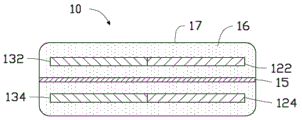
Fig. 1 is a schematic structural diagram of a hybrid energy storage device according to a first embodiment of the present invention.
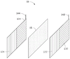
Fig. 2 is a schematic diagram of an arrangement of plates of a hybrid energy storage device according to a first embodiment of the present invention.
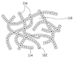
Fig. 3 is a partially enlarged view of the first electrode of the supercapacitor provided by the present invention.
Fig. 4 is a scanning electron micrograph of the carbon nanotube/polyaniline composite structure according to the first embodiment of the present invention.
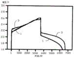
Fig. 5 is a constant current charging and discharging curve of the hybrid energy storage device according to the first embodiment of the present invention.
Description of the main elements
| Hybrid |
10,20 |
| |
112 |
| |
114 |
| Carbon nanotube |
116 |
| Micro-pores | 118 |
| First electrode of |
122 |
| Second electrode of |
124 |
| |
132 |
| Battery |
134 |
| |
142 |
| |
144 |
| |
15 |
| |
16 |
| |
17 |
The following detailed description will further illustrate the invention in conjunction with the above-described figures.
Detailed Description
The hybrid energy storage device provided by the invention will be further described in detail with reference to the accompanying drawings and specific embodiments.
Referring to fig. 1 and fig. 2 together, a hybrid energy storage device 10 is provided in a first embodiment of the present invention, in which the hybrid energy storage device 10 is composed of a super capacitor and a lead-acid battery connected in parallel. Specifically, the hybrid energy storage device 10 includes: a supercapacitor first electrode 122, a supercapacitor second electrode 124, a battery positive electrode 132, a battery negative electrode 134, a separator 15, an electrolyte 16, and a casing 17.
The supercapacitor first electrode 122, the supercapacitor second electrode 124, the battery positive electrode 132, the battery negative electrode 134 and the diaphragm 15 are all of a layered structure, are all arranged in the electrolyte 16, and are packaged in the shell 17 together with the electrolyte 16, the supercapacitor first electrode 122 and the battery positive electrode 132 are tiled to form a positive electrode of the hybrid energy storage device, the supercapacitor second electrode 124 and the battery negative electrode 134 are tiled to form a negative electrode of the hybrid energy storage device, the diaphragm 15 is arranged between the positive electrode of the hybrid energy storage device and the negative electrode of the hybrid energy storage device, the supercapacitor first electrode 122 and the supercapacitor second electrode 124 are arranged oppositely, and the battery positive electrode 132 and the battery negative electrode 134 are arranged oppositely.
The supercapacitor first electrode 122 and the supercapacitor second electrode 124 are respectively a first positive electrode and a first negative electrode of the hybrid energy storage device 10, and together form two electrodes of a supercapacitor. In this embodiment, a carbon nanotube macroscopic material is used as a skeleton, and polyaniline is composited on the carbon nanotube to obtain a carbon nanotube/polyaniline composite material for use as an electrode material of a supercapacitor. Referring to fig. 3, a partial enlarged view of a carbon nanotube/polyaniline composite according to an embodiment of the present invention is shown. The carbon nanotube/polyaniline composite material includes a carbon nanotube network 116 and a conductive polymer polyaniline layer 114, wherein the dotted line represents a carbon nanotube 112. The carbon nanotube network 116 is formed by connecting a plurality of carbon nanotubes 112 to each other. Adjacent carbon nanotubes 112 are connected to each other by van der waals force. In the carbon nanotube/polyaniline composite material, the carbon nanotube mesh structure 116 serves as a framework, and the polyaniline layer 114 is coated on the surface of the carbon nanotubes 112 in the carbon nanotube mesh structure 116, that is, the carbon nanotube mesh structure 116 can support the polyaniline layer 114, so that the polyaniline layer 114 can be distributed on the surface of the carbon nanotubes 112. In the present embodiment, the polyaniline layer 114 is uniformly distributed on the entire surface of the carbon nanotube mesh structure 116, that is, the polyaniline layer 114 is uniformly distributed on the surface of each carbon nanotube 112 in the carbon nanotube mesh structure 116. In addition, the carbon nanotube mesh structure 116 has a plurality of micropores 118. The micro-holes 118 are defined by a plurality of carbon nanotubes 112, and an inner surface of each micro-hole 118 is provided with an upper polyaniline layer 114. The size range of the micropores is 60-400 nanometers. Due to the existence of the plurality of micropores 118, the supercapacitor first electrode 122 and the supercapacitor second electrode 124 have smaller density and thus lighter weight. Because the supercapacitor first electrode 122 and the supercapacitor second electrode 124 are both made of composite materials composed of carbon nanotubes and polyaniline, the supercapacitor first electrode 122 and the supercapacitor second electrode 124 have very good flexibility and can be bent at will.
The carbon nanotube 112 includes one or more of a single-walled carbon nanotube, a double-walled carbon nanotube, and a multi-walled carbon nanotube. The diameter of the single-walled carbon nanotube is preferably 0.5 to 50 nanometers, the diameter of the double-walled carbon nanotube is preferably 1.0 to 50 nanometers, and the diameter of the multi-walled carbon nanotube is preferably 1.5 to 50 nanometers. The length of the carbon nanotubes is preferably between 100 nanometers and 10 millimeters. In this embodiment, the carbon nanotube network 116 formed by the carbon nanotubes 112 is a disordered carbon nanotube network. By "disordered" is meant that the carbon nanotubes 112 in the carbon nanotube network 116 are arranged in a random or isotropic manner. The carbon nanotubes 112 in the disordered array are attracted to each other, intertwined with each other, and uniformly distributed by van der waals force. Preferably, the carbon nanotubes 112 are substantially parallel to the surface of the carbon nanotube network 116.
The disordered carbon nanotube net structure comprises disordered carbon nanotube paper prepared by a vacuum filtration method, carbon nanotube pieces formed by flattening carbon nanotube powder under the pressure of more than 15MPa, and the like. In this embodiment, the carbon nanotube network structure is a disordered carbon nanotube paper prepared by a vacuum filtration method.
The carbon nano tube/polyaniline composite material can be prepared by the following method:
(1) Immersing the prepared carbon nano tube net structure into 40ml of aniline solution, and standing for 10 minutes, wherein the aniline solution contains 0.002M aniline monomer and 0.04M hydrochloric acid;
(2) Slowly adding pre-cooled 40ml of 0.002M ammonium persulfate solution into the solution, and standing the mixed solution at 0 ℃ for 24 hours;
(3) The carbon nanotube layer was taken out of the solution and the excess reaction solution was removed, and dried under vacuum at 80 ℃ for about 12 hours.
Fig. 4 is a scanning electron micrograph of the carbon nanotube/polyaniline composite material prepared by the above method. The carbon nanotube/polyaniline composite material is further cut into a film with the length of 1.4cm and the width of 1.2cm, and the first electrode 122 of the super capacitor and the second electrode 124 of the super capacitor can be obtained.
If only the carbon nano tube is used as the electrode of the super capacitor, the double electric layer capacitance provided by the super capacitor is about 80F/g, and the cycle life of the super capacitor is long; if the conductive polymer polyaniline is used as the electrode of the super capacitor, the redox pseudocapacitance is more than 10 times higher than the electric double layer capacitance, but the cycle life is short. The carbon nanotube/polyaniline composite material adopted in the embodiment combines the advantages of the carbon nanotube and the polyaniline, namely, the carbon nanotube/polyaniline composite material has higher specific capacitance (about 400F/g) and longer cycle life, has certain flexibility, and can be cut and bent at will.
The battery positive electrode 132 and the battery negative electrode 134 are respectively a second positive electrode and a second negative electrode of the hybrid energy storage device 10, and together form two electrodes of the battery. The battery refers to a device that converts chemical energy of positive and negative active materials into electric energy through oxidation-reduction reaction, and the active material refers to a plate material that generates electric energy through chemical reaction when the battery is discharged and recovers to an original composition when the battery is charged, for example, in a lead-acid battery, the active material of the positive electrode 132 of the battery is lead dioxide, the active material of the negative electrode 134 of the battery is lead, in a zinc-manganese battery, the active material of the positive electrode 132 of the battery is manganese dioxide, and the active material of the negative electrode 134 of the battery is zinc. Batteries are classified into primary batteries and secondary batteries according to the possibility of repeated charge and discharge cycles, the former cannot be recharged after the electricity is exhausted, and the latter can be recycled for many times. The battery type selected by the invention can be a primary battery, such as a zinc-manganese battery and a lithium metal battery; and may be a secondary battery such as a lead-acid battery or a lithium ion battery. The active materials of the battery positive electrode 132 and the battery negative electrode 134 are determined by the selected battery type. The battery selected in this example is a lead-acid battery, the positive active material of which is lead dioxide and the negative active material of which is lead. The length of the super capacitor is the same as or similar to the broadband of the super capacitor first electrode 122, and the thickness of the super capacitor is about 2mm to 4mm. In order to further improve the performance of the hybrid energy storage device 10, the electrode of the lead-acid battery may be modified, in which the modified positive electrode 132 is made of a carbon nanotube/lead dioxide composite material, and the negative electrode 134 is made of a carbon nanotube/lead composite material. The preparation process of the two composite materials is as follows: respectively ultrasonically dispersing the multi-wall carbon nano tube with lead dioxide powder and lead powder to fully mix the multi-wall carbon nano tube with the lead dioxide powder and the lead powder; and respectively carrying out suction filtration on the two mixtures to form a film shape, thus obtaining the required composite material.
The weight and volume of the battery positive electrode 132 and the battery negative electrode 134 manufactured by the above scheme are further reduced and have certain flexibility. The battery positive electrode 132 and the battery negative electrode 134, the supercapacitor first electrode 122, the supercapacitor second electrode 124, the diaphragm 15 and the shell 17 which are also flexible form the flexible hybrid energy storage device 10, and the hybrid energy storage device 10 can be bent, wound and folded at will and can be widely applied to wearable electronic equipment.
The battery positive electrode 132 further includes a positive current collector, one end of the positive current collector is provided with a positive electrode tab 142, the battery negative electrode 134 further includes a negative current collector, one end of the negative current collector is provided with a negative electrode tab 144. The current collector can provide an electron channel for electrochemical reaction to accelerate electron transfer and transfer electrons to an external circuit to form current. The mass flow body thickness can be 1 micron ~200 microns, the active material of battery positive electrode 132 cover in anodal mass flow body at least one surface, the active material of battery negative electrode 134 cover on the negative pole mass flow body at least one surface. The current collector can be a common positive current collector or a common negative current collector in the existing electrochemical battery, for example, the positive current collector can be a common cast grid, or a lead and lead alloy foil punched and drawn grid, or a lead-drawn grid; the negative current collector can be a common cast grid, or a lead and lead alloy foil flat plate, or a lead and lead alloy foil punched flat plate, or a lead and lead alloy punched net grid, or a lead net grid.
The diaphragm 15 is used for separating the positive electrode from the negative electrode to prevent direct contact of active substances of the two electrodes, and meanwhile, the diaphragm 15 also ensures that ions in the electrolyte can migrate between the positive electrode and the negative electrode, so that the diaphragm 15 is generally made of a non-metal material and is provided with a large number of micropores for the ions to pass through. The diaphragm 15 in this embodiment may be made of diaphragm materials commonly used in the art, such as: absorbent glass fiber membranes (AGM), microporous polypropylene membranes, and the like.
The electrolyte 16 is used to provide ions in a chemical reaction, and may be in liquid or gel form, and any acidic electrolyte suitable for lead-acid batteries may be used as the electrolyte 16 in this embodiment, preferably sulfuric acid. In the case of other types of batteries, the type of electrolyte can be selected by those skilled in the art as a matter of routine preference.
The supercapacitor first electrode 122, the supercapacitor second electrode 124, the battery positive electrode 132, the battery negative electrode 134, the diaphragm 15 and the electrolyte 16 are all packaged in a shell 17, wherein the supercapacitor first electrode 122 and the battery positive electrode 132 are tiled and arranged to be respectively used as a first positive electrode and a second positive electrode of the hybrid energy storage device 10 to jointly form a positive electrode of the hybrid energy storage device 10, and the supercapacitor second electrode 124 and the battery negative electrode 134 are tiled and arranged to be respectively used as a first negative electrode and a second negative electrode of the hybrid energy storage device 10 to jointly form a negative electrode of the hybrid energy storage device 10. By laid flat arrangement is meant that the two electrodes are in the same plane and have a common side in contact with each other. The first positive electrode and the first negative electrode are oppositely arranged to be used as a super capacitor, and the second positive electrode and the second negative electrode are oppositely arranged to be used as a battery. The housing 17 is a closed structure, and the electrolyte 16 inside the housing cannot penetrate outwards. The outer surface of the housing 17 has a positive output terminal and a negative output terminal for outputting electric energy, the positive output terminal is electrically connected to the positive electrode or the positive electrode tab 142 of the hybrid energy storage device disposed inside the housing 17, and the negative output terminal is electrically connected to the negative electrode or the negative electrode tab 144 of the hybrid energy storage device disposed inside the housing 17. The specific dimensions and dimensions of the housing 17 may further be referenced to existing universal battery packaging standards.
In the hybrid energy storage device 10 provided in this embodiment, the lead-acid battery and the super capacitor have a synergistic effect in the charging and discharging processes, that is, during the large-current charging period, the super capacitor is first charged quickly, then the super capacitor is discharged slowly, and the lead-acid battery is charged slowly at the same time. Therefore, during the large current charging and discharging process, the charging and discharging current of the lead-acid battery in the hybrid energy storage device 10 is smaller than the charging and discharging current of a single lead-acid battery under the same condition. The reduction of the current of the lead-acid battery in the large-current charging and discharging process can effectively protect the negative electrode 134 of the lead-acid battery, so that the service life of the hybrid energy storage device 10 is prolonged compared with that of the original lead-acid battery. Meanwhile, the reduction of the current of the lead-acid battery is also beneficial to the conversion of active substances on the positive electrode 132 and the negative electrode 134 of the battery, and the utilization rate of all electrode materials can be enhanced, so that the power of the hybrid energy storage device 10 is increased compared with that of the original lead-acid battery.
When the ratio between the battery electrode and the supercapacitor electrode is changed, the constant current charge and discharge performance of the hybrid energy storage device 10 is also changed correspondingly, when the weight ratio of the battery positive electrode 132 to the supercapacitor first electrode 122 is 1000 to 125, and the weight ratio of the battery negative electrode 134 to the supercapacitor second electrode 124 is 1000 to 1 to 125; particularly, when the weight ratio of the battery positive electrode 132 to the supercapacitor first electrode 122 is 1000. Fig. 5 is a comparison graph of the constant current charge and discharge curve (curve 3) of the hybrid energy storage device 10 and the constant current charge and discharge curve (curve 1) of the lead-acid battery when the mass ratio is 1000, and the corresponding test process steps are as follows:
1. the hybrid energy storage device 10 and the lead-acid battery are charged simultaneously in the charging process, the initial charging potential is 1.6V, the charging current is constant at 60mA, and the charging time is 1h;
2. and (3) immediately entering a discharging process after the charging process is finished in the discharging process, keeping the discharging current to be 60mA, continuously discharging, and finishing discharging when the voltage is reduced to 1.6V.
As can be seen from the curve in fig. 5, during the discharging process, the voltage of the hybrid energy storage device 10 provided by the present invention decreases to 1.6V when about 6600s, which is about 300s longer than the discharging time of the conventional lead-acid battery, and the constant current discharging voltage of the hybrid energy storage device 10 is significantly higher than that of the conventional lead-acid battery at the same time point.
The second embodiment of the invention provides a hybrid energy storage device 20, and the hybrid energy storage device 20 comprises a super capacitor and a zinc-manganese battery which are connected in parallel. Specifically, the hybrid energy storage device 20 includes: a supercapacitor first electrode 122, a supercapacitor second electrode 124, a battery positive electrode 132, a battery negative electrode 134, a separator 15, an electrolyte 16 and a casing 17.
The supercapacitor first electrode 122, the supercapacitor second electrode 124, the battery positive electrode 132, the battery negative electrode 134 and the diaphragm 15 are all of a layered structure, are all arranged in the electrolyte 16, and are packaged in the shell 17 together with the electrolyte 16, the supercapacitor first electrode 122 and the battery positive electrode 132 are tiled to form a hybrid energy storage device positive electrode, the supercapacitor second electrode 124 and the battery negative electrode 134 are tiled to form a hybrid energy storage device negative electrode, the diaphragm 15 is arranged between the hybrid energy storage device positive electrode and the hybrid energy storage device negative electrode, the supercapacitor first electrode 122 and the supercapacitor second electrode 124 are arranged oppositely, and the battery positive electrode 132 and the battery negative electrode 134 are arranged oppositely.
The battery positive electrode 132 and the battery negative electrode 134 are two electrodes of a battery, the length and the width of the battery positive electrode and the length and the width of the battery negative electrode are the same as or similar to those of the first electrode 122 of the super capacitor, and the thickness of the battery positive electrode and the battery negative electrode is about 2mm-4 mm. The active materials of the positive electrode 132 and the negative electrode 134 are determined by the selected battery type, and the battery in this embodiment is a zinc-manganese battery, the positive active material is manganese dioxide, and the negative active material is zinc. In order to further improve the performance of the hybrid energy storage device 20, the electrodes of the above-mentioned zn-mn battery may also be modified, in which the modified battery positive electrode 132 is made of a carbon nanotube/manganese dioxide composite material, and the battery negative electrode 134 is made of a carbon nanotube/zn composite material. The preparation process of the two composite materials is as follows: respectively ultrasonically dispersing the multi-walled carbon nano tube with manganese dioxide powder and zinc powder to fully mix the multi-walled carbon nano tube with the manganese dioxide powder and the zinc powder together; and respectively carrying out suction filtration on the two mixtures to form a film shape, thus obtaining the required composite material. The battery positive electrode 132 and the battery negative electrode 134 manufactured by the scheme have reduced weight and volume and flexibility. The battery positive electrode 132 and the battery negative electrode 134, the supercapacitor first electrode 122, the supercapacitor second electrode 124, the diaphragm 15 and the shell 17 which are also flexible can form the flexible hybrid energy storage device 10, and the hybrid energy storage device 10 can be bent, wound and folded at will and can be widely applied to wearable electronic equipment.
The electrolyte 16 in the present embodiment is preferably an ammonium chloride electrolyte, but any electrolyte suitable for a zinc-manganese battery may be used.
The hybrid energy storage device 20 provided in the present embodiment is different from the hybrid energy storage device 10 provided in the first embodiment described above in that the battery type connected in series with the super capacitor in the present embodiment is a zinc-manganese battery, and the battery type connected in series with the super capacitor in the hybrid energy storage device 10 provided in the first embodiment is a lead-acid battery.
The battery positive electrode 132 and the battery negative electrode 134 in the first embodiment of the present invention are of lead-acid battery type, and the battery positive electrode 132 and the battery negative electrode 134 in the second embodiment are of zinc-manganese battery type, but other battery electrode types may be used for the battery positive electrode 132 and the battery negative electrode 134 according to specific application situations, and the other batteries include: lithium metal batteries, lithium ion batteries, and the like. Electrode materials and electrode fabrication processes used in the various battery types described above are well known to those skilled in the art and are known from publications in the art.
Claims (10)
1. The utility model provides a hybrid energy storage device, includes a ultracapacitor system first electrode, a ultracapacitor system second electrode, a battery positive electrode, a battery negative electrode, a diaphragm, a shell and electrolyte, ultracapacitor system first electrode, ultracapacitor system second electrode, battery positive electrode, battery negative electrode and diaphragm are the lamellar structure, all set up in the electrolyte to together encapsulate in the shell its characterized in that with this electrolyte:
the positive electrode of the hybrid energy storage device consists of a first electrode of the super capacitor and a positive electrode of the battery, wherein the first electrode of the super capacitor and the positive electrode of the battery are tiled and arranged on the same plane and have a common side edge in mutual contact;
the cathode of the hybrid energy storage device consists of a second electrode of the super capacitor and a cathode electrode of the battery, wherein the second electrode of the super capacitor and the cathode electrode of the battery are tiled and arranged on the same plane and have a common side edge in mutual contact;
the diaphragm is arranged between the anode of the hybrid energy storage device and the cathode of the hybrid energy storage device and is used for separating the anode of the hybrid energy storage device from the cathode of the hybrid energy storage device;
the first electrode of the super capacitor is arranged opposite to the second electrode of the super capacitor, and the positive electrode of the battery is arranged opposite to the negative electrode of the battery; the first electrode of ultracapacitor system comprises carbon nanotube/polyaniline combined material, carbon nanotube/polyaniline combined material is the porous film that a plurality of carbon nanotubes and polyaniline constitute, a plurality of carbon nanotube interconnect form a carbon nanotube skeleton, every carbon nanotube's surface coating have by polyaniline layer that the polyaniline formed, battery positive electrode includes an anodal mass flow body, the one end of anodal mass flow body is equipped with anodal utmost point ear, anodal utmost point ear is connected with the anodal output electricity of shell.
2. The hybrid energy storage device of claim 1, wherein the weight ratio of the battery positive electrode to the first electrode of the supercapacitor is from 1000:1 to 125:1, and the weight ratio of the battery negative electrode to the second electrode of the supercapacitor is from 1000:1 to 125:1.
3. The hybrid energy storage device of claim 2, wherein the weight ratio of the battery positive electrode to the first electrode of the supercapacitor is 1000:3 and the weight ratio of the battery negative electrode to the second electrode of the supercapacitor is 1000: 3.
4. The hybrid energy storage device of claim 1, wherein the supercapacitor first electrode and the supercapacitor second electrode are made of a carbon nanotube/polyaniline composite.
5. The hybrid energy storage device of claim 4, wherein the carbon nanotube/polyaniline composite is prepared by a method comprising: immersing the prepared carbon nano tube net structure into aniline solution, slowly adding precooled ammonium persulfate solution into the aniline solution, taking out the carbon nano tube net structure, removing redundant reaction liquid and drying.
6. The hybrid energy storage device of claim 5, wherein said carbon nanotube backbone has a plurality of micropores defined by a plurality of carbon nanotubes, and wherein an inner surface of each micropore is provided with said polyaniline layer.
7. The hybrid energy storage device of claim 6, wherein the carbon nanotubes in the carbon nanotube backbone are randomly arranged, and wherein the randomly arranged carbon nanotubes attract each other, intertwine each other, and are uniformly distributed in the carbon nanotube backbone by van der waals forces.
8. The hybrid energy storage device of claim 1, wherein the battery positive electrode is made of a carbon nanotube/lead dioxide composite and the battery negative electrode is made of a carbon nanotube/lead composite.
9. The hybrid energy storage device of claim 1, wherein the battery positive electrode is made of a carbon nanotube/manganese dioxide composite and the battery negative electrode is made of a carbon nanotube/zinc composite.
10. A hybrid energy storage device, includes a diaphragm, an anodal, a negative pole and electrolyte, the diaphragm sets up between anodal and negative pole, anodal, negative pole and diaphragm all set up in the electrolyte, its characterized in that: the positive electrode comprises a first positive electrode and a second positive electrode which are arranged in a tiled manner, the negative electrode comprises a first negative electrode and a second negative electrode which are arranged in a tiled manner, the first positive electrode and the first negative electrode are oppositely arranged to be used as a super capacitor, the second positive electrode and the second negative electrode are oppositely arranged to be used as a battery, wherein the weight ratio of the second positive electrode to the first positive electrode is 1000: 1-125: 1, and the weight ratio of the second negative electrode to the first negative electrode is 1000: 1-125: 1; the first positive pole and the second positive pole are positioned on the same plane and are provided with a mutual contact common side edge, and the first negative pole and the second negative pole are positioned on the same plane and are provided with a mutual contact common side edge; the first positive electrode is composed of a carbon nano tube/polyaniline composite material, the carbon nano tube/polyaniline composite material is a porous film composed of a plurality of carbon nano tubes and polyaniline, the plurality of carbon nano tubes are connected with one another to form a carbon nano tube framework, and the surface of each carbon nano tube is wrapped with a polyaniline layer formed by the polyaniline; the second positive pole includes a positive mass flow body, the one end of the positive mass flow body is equipped with anodal utmost point ear, anodal utmost point ear is connected with the anodal output electricity of shell.
Priority Applications (2)
| Application Number | Priority Date | Filing Date | Title |
|---|---|---|---|
| CN201410211141.8A CN105097289B (en) | 2014-05-19 | 2014-05-19 | Hybrid energy storage device |
| US14/451,838 US9576747B2 (en) | 2014-05-19 | 2014-08-05 | Hybrid energy storage device |
Applications Claiming Priority (1)
| Application Number | Priority Date | Filing Date | Title |
|---|---|---|---|
| CN201410211141.8A CN105097289B (en) | 2014-05-19 | 2014-05-19 | Hybrid energy storage device |
Publications (2)
| Publication Number | Publication Date |
|---|---|
| CN105097289A CN105097289A (en) | 2015-11-25 |
| CN105097289B true CN105097289B (en) | 2020-12-04 |
Family
ID=54539083
Family Applications (1)
| Application Number | Title | Priority Date | Filing Date |
|---|---|---|---|
| CN201410211141.8A Active CN105097289B (en) | 2014-05-19 | 2014-05-19 | Hybrid energy storage device |
Country Status (2)
| Country | Link |
|---|---|
| US (1) | US9576747B2 (en) |
| CN (1) | CN105097289B (en) |
Families Citing this family (11)
| Publication number | Priority date | Publication date | Assignee | Title |
|---|---|---|---|---|
| US10062922B2 (en) * | 2015-01-26 | 2018-08-28 | University Of Dayton | Lithium batteries having artificial solid electrolyte interphase membrane for anode protection |
| GB2553128B (en) * | 2016-08-24 | 2020-02-26 | Dst Innovations Ltd | Rechargeable power cells |
| CN107068962A (en) * | 2016-12-08 | 2017-08-18 | 德阳九鼎智远知识产权运营有限公司 | A kind of negative electrode of secondary battery preparation method |
| CN109435672B (en) * | 2017-08-24 | 2022-12-02 | 通用汽车环球科技运作有限责任公司 | System and method for monitoring a hybrid energy storage device |
| CN109427489A (en) | 2017-08-24 | 2019-03-05 | 通用汽车环球科技运作有限责任公司 | Supercapacitor control system and method |
| CN109599270B (en) * | 2017-09-30 | 2020-08-11 | 清华大学 | Preparation method of photoelectric self-energy storage device |
| JP7218423B2 (en) * | 2018-07-18 | 2023-02-06 | ケメット エレクトロニクス コーポレーション | Hybrid capacitor and method of manufacturing capacitor |
| CN110136972A (en) * | 2019-04-25 | 2019-08-16 | 南京国轩电池有限公司 | A kind of preparation method of multilayer hierarchical structure supercapacitor composite material |
| CN111952079B (en) * | 2019-05-17 | 2022-04-22 | 清华大学 | Energy storage device capable of continuously charging |
| US11404714B2 (en) * | 2019-07-26 | 2022-08-02 | GM Global Technology Operations LLC | Capacitor assisted bipolar battery |
| CN112448069A (en) * | 2020-11-17 | 2021-03-05 | 河北工业大学 | Metal-air battery and super capacitor integrated device and preparation method thereof |
Citations (4)
| Publication number | Priority date | Publication date | Assignee | Title |
|---|---|---|---|---|
| CN101671478A (en) * | 2009-09-27 | 2010-03-17 | 西南交通大学 | Preparation method of carbon nano tube/polyaniline netty compound material |
| CN101847764A (en) * | 2010-02-26 | 2010-09-29 | 上海奥威科技开发有限公司 | High-specific-energy/high-specific-power type super battery |
| CN103050290A (en) * | 2012-12-20 | 2013-04-17 | 上海奥威科技开发有限公司 | Internally combined super capacitor |
| CN103531854A (en) * | 2012-07-04 | 2014-01-22 | 北京精密机电控制设备研究所 | Novel power supply with comprehensive performances of supercapacitor and zinc-silver battery |
Family Cites Families (6)
| Publication number | Priority date | Publication date | Assignee | Title |
|---|---|---|---|---|
| US7029794B2 (en) * | 1998-03-31 | 2006-04-18 | Celanese Ventures Gmbh | Lithium battery and electrode |
| WO2008124167A1 (en) * | 2007-04-10 | 2008-10-16 | The Regents Of The University Of California | Charge storage devices containing carbon nanotube films as electrodes and charge collectors |
| CN100590761C (en) * | 2008-06-16 | 2010-02-17 | 中南大学 | Process for manufacturing super capacitor battery |
| WO2010028162A2 (en) * | 2008-09-04 | 2010-03-11 | The Regents Of The University Of California | Charge storage device architecture for increasing energy and power density |
| CN101937776B (en) * | 2010-07-14 | 2011-12-21 | 清华大学 | Super capacitor |
| US20130171502A1 (en) * | 2011-12-29 | 2013-07-04 | Guorong Chen | Hybrid electrode and surface-mediated cell-based super-hybrid energy storage device containing same |
-
2014
- 2014-05-19 CN CN201410211141.8A patent/CN105097289B/en active Active
- 2014-08-05 US US14/451,838 patent/US9576747B2/en active Active
Patent Citations (4)
| Publication number | Priority date | Publication date | Assignee | Title |
|---|---|---|---|---|
| CN101671478A (en) * | 2009-09-27 | 2010-03-17 | 西南交通大学 | Preparation method of carbon nano tube/polyaniline netty compound material |
| CN101847764A (en) * | 2010-02-26 | 2010-09-29 | 上海奥威科技开发有限公司 | High-specific-energy/high-specific-power type super battery |
| CN103531854A (en) * | 2012-07-04 | 2014-01-22 | 北京精密机电控制设备研究所 | Novel power supply with comprehensive performances of supercapacitor and zinc-silver battery |
| CN103050290A (en) * | 2012-12-20 | 2013-04-17 | 上海奥威科技开发有限公司 | Internally combined super capacitor |
Also Published As
| Publication number | Publication date |
|---|---|
| US9576747B2 (en) | 2017-02-21 |
| US20150332861A1 (en) | 2015-11-19 |
| CN105097289A (en) | 2015-11-25 |
Similar Documents
| Publication | Publication Date | Title |
|---|---|---|
| CN105097289B (en) | Hybrid energy storage device | |
| CN105576277B (en) | rechargeable battery | |
| CN111785898B (en) | Cellulose-based integrated zinc ion battery and preparation method thereof | |
| CN105098293A (en) | Hybrid energy storage device | |
| CN107305942B (en) | Winding type negative plate, battery cell with same and lithium slurry battery | |
| CN110176591A (en) | A kind of preparation method of water system zinc ion secondary cell and its anode based on organic electrode materials | |
| CN102971889A (en) | High energy density electrochemical capacitors | |
| JP5680868B2 (en) | Lithium ion capacitor | |
| CN111952079B (en) | Energy storage device capable of continuously charging | |
| CN103000390B (en) | A kind of negative pole currect collecting preparation and use the ultracapacitor of this collector | |
| CN104241601A (en) | Preparation method of metal-current-collector-free lithium battery or super-capacitor electrode | |
| CN104599859A (en) | Lithium ion capacitor and manufacturing method thereof | |
| WO2020118880A1 (en) | Graphite positive electrode and zinc negative electrode-based hybrid super capacitor | |
| CN110729529A (en) | Energy storage battery cell with composite electrode structure and method for pre-embedding lithium in battery cell | |
| KR102098065B1 (en) | Three-dimensional porous-structured electrode, methode of manufacturing and electrochemical device having the electrode | |
| CN210272536U (en) | Novel negative plate and lithium ion battery | |
| WO2016045622A1 (en) | Battery, battery pack and continuous power supply | |
| JP6618183B2 (en) | Secondary battery, charging device and discharging device | |
| CN106876714A (en) | A kind of lithium ion battery for automobile starting/stopping system | |
| CN111180730A (en) | Rapid charging and discharging graphene power lithium battery and preparation method thereof | |
| CN107452918B (en) | Rare earth new power supply and preparation method thereof | |
| CN201886904U (en) | Laminated high-voltage mixing electrochemical capacitor | |
| CN110323483A (en) | Secondary cell and preparation method thereof with include its power device | |
| CN103996854A (en) | Electrochemical hybrid energy storage device | |
| JP2014521231A (en) | Energy storage device, inorganic gel electrolyte, and method thereof |
Legal Events
| Date | Code | Title | Description |
|---|---|---|---|
| C06 | Publication | ||
| PB01 | Publication | ||
| C10 | Entry into substantive examination | ||
| SE01 | Entry into force of request for substantive examination | ||
| GR01 | Patent grant | ||
| GR01 | Patent grant |