CN1050724C - Gray scale printing using spatial light modulator - Google Patents
Gray scale printing using spatial light modulator Download PDFInfo
- Publication number
- CN1050724C CN1050724C CN94103183A CN94103183A CN1050724C CN 1050724 C CN1050724 C CN 1050724C CN 94103183 A CN94103183 A CN 94103183A CN 94103183 A CN94103183 A CN 94103183A CN 1050724 C CN1050724 C CN 1050724C
- Authority
- CN
- China
- Prior art keywords
- row
- width modulation
- line
- pulse
- spatial light
- Prior art date
- Legal status (The legal status is an assumption and is not a legal conclusion. Google has not performed a legal analysis and makes no representation as to the accuracy of the status listed.)
- Expired - Fee Related
Links
- 238000007639 printing Methods 0.000 title claims abstract description 25
- 238000000034 method Methods 0.000 claims abstract description 24
- 230000008569 process Effects 0.000 description 8
- 230000008901 benefit Effects 0.000 description 6
- 238000006243 chemical reaction Methods 0.000 description 4
- 230000007547 defect Effects 0.000 description 4
- 238000010586 diagram Methods 0.000 description 4
- 230000000694 effects Effects 0.000 description 2
- 239000000463 material Substances 0.000 description 2
- 230000008859 change Effects 0.000 description 1
- 239000002131 composite material Substances 0.000 description 1
- 150000001875 compounds Chemical class 0.000 description 1
- 230000007812 deficiency Effects 0.000 description 1
- 238000009434 installation Methods 0.000 description 1
- 230000010354 integration Effects 0.000 description 1
- 238000007648 laser printing Methods 0.000 description 1
- 238000001208 nuclear magnetic resonance pulse sequence Methods 0.000 description 1
- 230000004044 response Effects 0.000 description 1
- 229920006395 saturated elastomer Polymers 0.000 description 1
- 230000007480 spreading Effects 0.000 description 1
Images


Classifications
-
- H—ELECTRICITY
- H04—ELECTRIC COMMUNICATION TECHNIQUE
- H04N—PICTORIAL COMMUNICATION, e.g. TELEVISION
- H04N1/00—Scanning, transmission or reproduction of documents or the like, e.g. facsimile transmission; Details thereof
- H04N1/40—Picture signal circuits
-
- H—ELECTRICITY
- H04—ELECTRIC COMMUNICATION TECHNIQUE
- H04N—PICTORIAL COMMUNICATION, e.g. TELEVISION
- H04N1/00—Scanning, transmission or reproduction of documents or the like, e.g. facsimile transmission; Details thereof
- H04N1/40—Picture signal circuits
- H04N1/405—Halftoning, i.e. converting the picture signal of a continuous-tone original into a corresponding signal showing only two levels
- H04N1/4055—Halftoning, i.e. converting the picture signal of a continuous-tone original into a corresponding signal showing only two levels producing a clustered dots or a size modulated halftone pattern
- H04N1/4056—Halftoning, i.e. converting the picture signal of a continuous-tone original into a corresponding signal showing only two levels producing a clustered dots or a size modulated halftone pattern the pattern varying in one dimension only, e.g. dash length, pulse width modulation [PWM]
-
- H—ELECTRICITY
- H04—ELECTRIC COMMUNICATION TECHNIQUE
- H04N—PICTORIAL COMMUNICATION, e.g. TELEVISION
- H04N1/00—Scanning, transmission or reproduction of documents or the like, e.g. facsimile transmission; Details thereof
- H04N1/40—Picture signal circuits
- H04N1/40025—Circuits exciting or modulating particular heads for reproducing continuous tone value scales
- H04N1/40031—Circuits exciting or modulating particular heads for reproducing continuous tone value scales for a plurality of reproducing elements simultaneously
Landscapes
- Engineering & Computer Science (AREA)
- Multimedia (AREA)
- Signal Processing (AREA)
- Facsimile Image Signal Circuits (AREA)
- Laser Beam Printer (AREA)
- Color, Gradation (AREA)
- Dot-Matrix Printers And Others (AREA)
- Fax Reproducing Arrangements (AREA)
- Mechanical Light Control Or Optical Switches (AREA)
- Image Processing (AREA)
Abstract
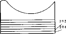
本发明提供一种将行组合与脉宽调制结合在一起的灰度印刷方法。空间光调器(102)有一条线(104),用于在给定的线时间内实现脉宽调制。调制器(106)的另一个区域有几条线,用于对印刷的图像实现行组合,以产生更多的灰度级。还可指定一辅助区域(108),用于校正光照曲线和印刷图像的缺陷。
The invention provides a grayscale printing method combining line combination and pulse width modulation. The spatial light modulator (102) has a line (104) for achieving pulse width modulation within a given line time. Another area of the modulator (106) has several lines for line combining of the printed image to produce more gray levels. An auxiliary area (108) may also be designated for correcting light curve and print image imperfections.
Description
本申请与下列申请同时提出:This application is filed concurrently with the following applications:
“空间光调制器的组合调制方法”,序列号________;TI-17335;"Combination modulation method of spatial light modulator", serial number ________; TI-17335;
“数字微镜印刷机的照相制版方法和结构”,序列号_______;TI-17632。"Photographic method and structure of digital micromirror printing machine", serial number _______; TI-17632.
本发明涉及使用空间光调制器(SLM)的印刷机,尤其涉及使用空间光调制器的灰度印刷。This invention relates to printing presses using spatial light modulators (SLMs), and more particularly to grayscale printing using spatial light modulators.
用空间光调制器实现灰度印刷存在几个难点。使用双态空间光调制器时,其元件仅能开或关。在印刷系统中,这意味着感光介质或者从元件接收到光,或者没有。如果没有接收到光,鼓不能取得上色剂,印页上的该点保持空白。如果感光介质接收到光,鼓取得上色剂,印页上的该点变黑。在大多数双态空间光调制器中,无法对感光介质作模拟式曝光以取得少量的上色剂。There are several difficulties in achieving grayscale printing with spatial light modulators. When using a two-state spatial light modulator, its elements can only be turned on or off. In printing systems, this means that the photosensitive media either receives light from the element, or it does not. If no light is received, the drum cannot pick up toner and the spot on the printed sheet remains blank. If the photosensitive medium receives light, the drum picks up toner and that spot on the printed sheet becomes black. In most two-state spatial light modulators, it is not possible to simulate exposure of the photosensitive medium to obtain a small amount of toner.
在使用激光源时激光印刷系统能通过对光作模拟式调制来实现灰度梯度。然而,作这种模拟式调制的激光系统的速度不足以实现最小灰度级。激光扫描系统通过使激光束沿光栅行逐个扫描像素进行印刷。例如,用户要在8.5″×11″的纸上以600点/英寸(dpi),每分钟40页的速率印刷。每页有11″×600dpi即6600行。每分钟40页相当于每秒4400行,每行有8.5×600,即5100个像素。这就要求每秒22.44×106个像素,每个像素占44.6毫微秒。在这样短的像素时间内激光模拟式调制无法给出足够的灰度梯度曝光量。有些SLM(空间光调制器)有这种能力。When using a laser source, a laser printing system can achieve grayscale gradients by analog modulation of light. However, laser systems for such analog modulation are not fast enough to achieve minimum gray levels. Laser scanning systems print by scanning a laser beam pixel by pixel along a raster row. For example, a user wants to print at a rate of 40 pages per minute at 600 dots per inch (dpi) on 8.5" x 11" paper. Each page has 11″×600dpi or 6600 lines. 40 pages per minute is equivalent to 4400 lines per second, and each line has 8.5×600, or 5100 pixels. This requires 22.44×10 6 pixels per second, and each pixel occupies 44.6 nanoseconds. In such a short pixel time, laser analog modulation cannot give enough gray-scale gradient exposure. Some SLMs (spatial light modulators) have this capability.
在此揭示的本发明提供一种使用空间光调制器来实现灰度印刷的方法。本发明的一个实施例是,在双态空间光调制器的一行上使用对称脉宽调制并用其它行进行行组合(row integration)。The invention disclosed herein provides a method of using spatial light modulators to achieve gray scale printing. One embodiment of the invention is to use symmetrical pulse width modulation on one row of a two-state spatial light modulator and row integration with the other rows.
本发明的优点是,以高分辨率实现多级灰度梯度。其深一层的优点在于脉宽调制能在移动感光介质的行时间内快速进行。第二个深一层优点是对装置进行数据装载的速率保持在易控制的速率上。第三个深一层的优点是提供了一种补偿阵列中缺陷的方法。The advantage of the present invention is that multi-level grayscale gradients are realized with high resolution. Its further advantage is that pulse width modulation can be performed quickly within the line time of moving the photosensitive medium. A second further advantage is that the rate at which data is loaded to the device remains at a manageable rate. A third further advantage is to provide a way to compensate for imperfections in the array.
为了更全面地了解本发明及其深一层的优点,现参照附图作如下详细说明:In order to more fully understand the present invention and its further advantages, now refer to the accompanying drawings for the following detailed description:
图1示出了双态空间光调制器正面上带有行组合和已校正行组合区域的一行脉宽调制的方块图。Figure 1 shows a block diagram of a row of pulse width modulation with row combining and corrected row combining regions on the front side of a dual-state spatial light modulator.
图2a-e图示了在元件行内,装置正面上的数据的移动。Figures 2a-e illustrate the movement of data on the front side of a device within a row of elements.
图3示出了数据装载和复位序列的时间图。Figure 3 shows a timing diagram of the data load and reset sequence.
图4示出曝光时间的柱状图。Figure 4 shows a histogram of exposure time.
图5a-c示出了双态脉宽调制的曝光曲线图。Figures 5a-c show exposure profiles for binary pulse width modulation.
图6a-b示出了对称脉宽调制器的曝光曲线图。Figures 6a-b show exposure curves for a symmetrical pulse width modulator.
脉宽调制(PWM)一般存在于图像印刷中用于实现灰度和彩色梯度。通常,PWM(脉宽调制)需对有效数据位加权,并用对应于其加权值的时间长度来表示那些位。例如,在4位系统中,系统用总帧时间的1/2表示最高有效位(MSB),一般在16毫秒左右。次有效位为1/4总帧时间,再次位为1/8总帧时间,最次有效位为1/16总帧时间。显示系统靠观者的眼睛把这些脉冲组合成灰色或彩色梯度。如将作进一步讨论的一样,印刷系统并不限于整数级的脉宽调制。虽然在脉宽调制中不可能获得“分数的”灰度级,但对于灰度级为最小有效行组合时间的分数的印刷系统有可能获得“分数”灰度级。Pulse Width Modulation (PWM) is commonly used in graphic printing to achieve grayscale and color gradients. Typically, PWM (Pulse Width Modulation) weights the valid data bits and represents those bits with a length of time corresponding to their weighted value. For example, in a 4-bit system, the system represents the most significant bit (MSB) for 1/2 of the total frame time, typically around 16 milliseconds. The least significant bit is 1/4 of the total frame time, the second bit is 1/8 of the total frame time, and the least significant bit is 1/16 of the total frame time. Display systems rely on the viewer's eyes to combine these pulses into gray or color gradients. As will be discussed further, printing systems are not limited to integer order pulse width modulation. Although it is not possible to obtain "fractional" gray levels in pulse width modulation, it is possible to obtain "fractional" gray levels for printing systems whose gray levels are fractions of the minimum effective line combination time.
在印刷中,用线时间取代帧时间。线时间是扫过感光介质上的空间光调制器的一行长度所用的时间量。这时间一般非常短,因此只能用较少的时间去对装置进行装载。装置通常在下一组数据装入到装置中和准备复位信号时显示一组数据。In printing, line time is used instead of frame time. Line time is the amount of time it takes to sweep the length of a line of the spatial light modulator on the photosensitive medium. This time is generally very short, so less time can be used to load the device. The device usually displays a set of data when the next set of data is loaded into the device and ready to reset the signal.
在有些空间光调制器中,例如在数字微镜装置(DMD)(也称为应变镜装置)中,复位脉冲使镜面阵列中的各元件能对其定址电路中的新数据起反应,调整元件以反射新数据。例如,假设元件处于“通”(ON)位置。当它显示该数据时,“关”(OFF)数据装入到定址电路内。如果有复位脉冲,该元件将记录新数据,翻转成“关”。当然,在“通”数据后可以跟“通”数据,在“关”数据后可以跟“关”数据,在这些情况下,该元件不改变状态就能反射新数据。这种复位方法通常需要在复位之前装载整个装置,需要较高的数据速率。In some spatial light modulators, such as digital micromirror devices (DMDs) (also known as strained mirror devices), a reset pulse enables each element in the mirror array to respond to new data in its addressing circuit, adjusting the element to reflect new data. For example, assume a component is in the "ON" position. When it displays the data, "OFF" data is loaded into the addressing circuit. If there is a reset pulse, the element will record new data, flipping "off". Of course, "on" data can be followed by "on" data, and "off" data can be followed by "off" data, in which case the element can reflect the new data without changing state. This method of reset typically requires loading the entire device prior to reset, requiring a higher data rate.
由于时间的限制、光转换的低效率以及在这受限制的时间内要装载所需的高数据速率的原故,因此,用脉宽调制印刷难以实现较大量的灰度级。Larger numbers of gray levels are difficult to achieve with pulse width modulated printing due to time constraints, inefficiencies in light conversion, and the high data rates required to load within this limited time.
然而,使用有独立元件的空间光调器的优点之一是可以把一些元件线放置一边(即不管这些无件线)或者指定一些元件线以实现某些不同的功能。在本发明的一个实施例中,对多行空间光调制器中的一行进行脉宽调制(PWM)。因此,仅仅一行数据需要快速更新,在其它行上的数据可锁住,并在该行的复位周期期间保持住。However, one of the advantages of using a spatial light modulator with individual elements is that some element lines can be set aside (ie, disregarded) or assigned to some different function. In one embodiment of the invention, one row of the multi-row spatial light modulator is pulse width modulated (PWM). Therefore, only one row of data needs to be updated quickly, and the data on other rows can be locked and held during the reset cycle of that row.
这种方法可以与行组合结合使用,这种行组合为现有技术,其中,数据线通过向上或向下移动调制器面来“跟踪”或跟随感光介质的同一区域,同鼓相对于调制器的移动情况无关。可打开或关闭某几条线的数据,实现灰度级。16线的行组合可有16级灰度,不包括所有线均关闭(白)的情况。空间间隔可以是所有16条线,或者15条线等。This approach can be used in conjunction with row combinations, which are known in the art, where the data lines "track" or follow the same area of the photosensitive media by moving the modulator face up or down, with the drum relative to the modulator. The movement situation is irrelevant. The data of certain lines can be turned on or off to achieve gray scale. A row combination of 16 lines can have 16 gray levels, excluding the case where all lines are turned off (white). Spacing can be all 16 lines, or 15 lines, etc.
例如,将这两种方法结合,一条2比特的脉宽调制线可有4级可能的灰度。对于128线行组合,4级可能的灰度与128级可能的灰度结合等于128×4即512级灰度。最一般的解释是,行组合提供整数灰度级,脉宽调制提供分数灰度级,这里分数灰度级即为最小有效行组合灰度级的分数。这512灰度被称为实际的灰度级。下面示出了实现这些级的比较结果。For example, combining these two methods, a 2-bit PWM line can have 4 possible gray levels. For a combination of 128 lines and rows, the combination of 4 possible gray levels and 128 possible gray levels equals 128×4,
例如,2比特PWM加上128行组合级来实现512级灰度的情况在平均数据速度上仅是简单的128行行组合的1.02倍。如果仅用行组合来实现512级灰度,数据速度将增加3倍。For example, the case of 2-bit PWM plus 128-row combination level to achieve 512-level gray scale is only 1.02 times faster than the simple 128-row combination on the average data speed. If only line combination is used to achieve 512 levels of gray, the data speed will increase by 3 times.
在下表中,假设装置的宽度为500点,印刷速度为5英寸/秒,印刷密度为600dpi,有48个输入。计算得到的数据速度为:In the following table, it is assumed that the width of the device is 500 dots, the printing speed is 5 inches/second, the printing density is 600dpi, and there are 48 inputs. The calculated data speed is:
平均数据速度=装置宽度(500点)×有效长度×印刷速度(5英寸/秒)×印刷密度(600dpi)÷输入数(48)
nI=行组合比特数;np=脉宽调制比特数;n I = number of row combination bits; n p = number of pulse width modulation bits;
RI=行组合;峰值数据速率只是相对于nI=7时的“仅有行组合”的情况。RI = row combining; the peak data rate is only relative to the "row combining only" case when n I =7.
从上表可以看出,当将脉宽调制应用于整个装置时,其数据速率比仅在一行上进行脉宽调制高得多。通常,平均带宽不象峰值带宽那样重要,峰值带宽决定了对装载电路的最高要求,对于仅有行组合的情况,其峰值数据速率与平均数据速率相等。例如,如果装置有128行,设计者希望有512级灰度。一种可能是使用512线行组合阵列,带宽将增加3倍。As can be seen from the table above, when PWM is applied to the entire device, the data rate is much higher than when PWM is applied to only one row. Usually, the average bandwidth is not as important as the peak bandwidth, which determines the maximum demand on the loading circuit, and for the case of only row combination, the peak data rate is equal to the average data rate. For example, if the device has 128 lines, the designer wishes to have 512 levels of gray. One possibility is to use a 512-row combined array, which would increase the bandwidth by a factor of three.
换句话说,可使用在整个装置上进行2比特脉宽调制的方法,并在整个装置在脉宽调制的最低有效位(LSB)时间内必须进行更新时将带宽增加2n倍。如果,仅脉宽调制一行,其峰值数据速率仅比上述的高2倍,因为整个阵列需要在脉宽调制的最高有效位(MSB)时间内更新,该时间等于行组合单元时间的1/2。如果一行脉宽调制提供所有9级灰度(没有行组合),则数据速率是7位行组合情况的4倍,因为在脉宽调制的最低有效位时间(1/2np行时间)内需要更新一行。在1行脉宽调制例子中还存在更严重问题,因为光源需要更大的功率使在短的行时间内产生有效的曝光。上述的数字仅仅是这些数据速率的一个例子,因为设计者可选择脉宽调制比特数和行组合的行。In other words, it is possible to use 2-bit PWM across the entire device and increase the bandwidth by a factor of 2n when the entire device has to be updated within the least significant bit (LSB) time of the PWM. If, only one row is pulse width modulated, its peak data rate is only 2 times higher than the above, because the entire array needs to be updated within the most significant bit (MSB) time of the pulse width modulation, which is equal to 1/2 the time of the row combination unit . If one row of PWM provides all 9 levels of gray (without row combining), the data rate is 4 times that of the 7-bit row-combining case, because within the least significant bit time (1/2 np row time) of the PWM requires Update a row. A more serious problem exists in the 1-line PWM example because more power is required from the light source to produce an effective exposure within a short line time. The above figures are only an example of these data rates, since the designer can choose the number of PWM bits and the row combination.
采用其他的将行组合与脉宽调制结合的方法是可能的。例如,在512级灰度的一个方案中,通过行组合实现128级,通过脉宽调制实现4级。需要128+1即129行的空间光调制器。在每128个行组合步骤中,在进行第129行的行组合时,对上面128行进行脉宽调制。这一周期重复进行。其平均带宽与单一的脉宽调制情况一样,但峰值速率是基行的2n-1倍。Other methods of combining row combining with pulse width modulation are possible. For example, in a scheme of 512 gray levels, 128 levels are realized through line combination, and 4 levels are realized through pulse width modulation. A spatial light modulator with 128+1 or 129 rows is required. In every 128 row combination steps, when performing the row combination of the 129th row, pulse width modulation is performed on the upper 128 rows. This cycle is repeated. Its average bandwidth is the same as that of a single PWM, but the peak rate is 2n -1 times that of the base line.
实际实现的灰度级很多,然而,人眼看得见的或者觉察得出的灰度级很少。人眼仅能觉察到这么多的灰度梯度,仅能在实际灰度级412和512之间看见一个灰度级。对灰度级的其它限制因素由上色剂和有机感光物(OPC)产生。与上色剂密度有关的是,第412级已使上色剂饱和,因此,它与第152级相比并无不同。有机感光物有一放电(discharge)曲线,在能量转换的某级之后,当超过该级时有机感光物所记录的就不再变化了。There are many gray levels that are actually realized, however, there are very few gray levels that can be seen or perceived by the human eye. The human eye can only perceive so many gray scale gradients, and only see one gray level between 412 and 512 actual gray levels. Other limiting factors on grayscale are created by toners and organic photosensitive compounds (OPCs). In relation to toner density, grade 412 has saturated the toner, so it is no different than grade 152. The organic photosensitive material has a discharge curve. After a certain level of energy conversion, when the level is exceeded, the recorded data of the organic photosensitive material will not change anymore.
另一个因素是整个印刷过程的非线性。例如,从计算机或扫描器输入的图像可有256个灰度级。当这些数据经过处理后输入到印刷机时,在一些明暗间隔非常“近”或非常远的灰度级上可能产生非性线。校正这种非线性的一种可能的方法是采用查找表,一些输入的灰度级与某一输出级对应,查找表是利用印刷机特性曲线预先确定的。Another factor is the nonlinearity of the entire printing process. For example, an image input from a computer or scanner may have 256 gray levels. When these data are processed and input to the printing press, non-linear lines may be generated on some gray levels with very "close" or very far intervals between light and dark. One possible way to correct this non-linearity is to use a look-up table, some input gray level corresponds to a certain output level, the look-up table is predetermined using the printing press characteristic curve.
图1示出了在SLM(空间光调制器面上线是如何定位的。该例子示出了有128线行组合的4比特脉宽调制,但也能适合于特定的系统和用途的需要。线104是脉宽调制的指定行。该线实际上可出现在阵列的任何位置上。最好是使用元件上的一条特定线,尤其是一条没有缺陷的线。的确,行组合的行不被限制于装置上的物理行。根据装置的定址结构和分散复位的这些特征,可用两行或更多行形成脉宽调制的一个“逻辑行”。图中示出了在线104之后的行组合区域106,它以图中箭头所示的过程方向进行,但也可在脉宽调制线周围,或者在它之前。在行组合区域106之上的是校正行组合区域108。Figure 1 shows how the wires are positioned on the SLM (Spatial Light Modulator) plane. The example shows 4-bit PWM with 128 line-row combinations, but can also be adapted to specific system and application needs.
该区域很可能处于过程方向上的阵列的终端,使能校正前几行出现的缺陷。这种可校正的缺陷可以由一给定行内的不能正常工作的单元引起的。校正区域可在以后的时间里用于重复该位置和不能正常工作的单元转换的能量,从而校正能量转换的损失。使用校正区域的这种方法和其它方法可采用查找表,查找表应预先装入校正器,并在需要时访问它。This area is likely to be at the end of the array in the process direction, enabling correction of defects present in the first few rows. Such correctable defects can be caused by non-functioning cells within a given row. The correction area can be used at a later time to repeat the position and the energy converted by the non-functioning unit, thereby correcting for the loss of energy conversion. This and other methods of using correction regions can employ look-up tables that should be preloaded with the corrector and accessed as needed.
为将数据速率保持在最小并使装置能再装载入数据,数据移动情况如图2a-2e所示。在图2a中,调制器202的线204表示第0行的最低有效位。在这种装置的结构中,这将在过程刚开始处发生,并且为纸上第一次。一般脉宽调制固有的次序首先表示脉宽调制数据的最高有效位。然而,在该实施例中,行组合数据在所有脉宽调制间隔内保持相同,整个装置在最后一个脉宽调制周期期间更新。如果在固有次序内发生脉宽调制,整个装置必须在最低有效位的时间内更新,对于4比特系统,最低有效位B时间仅为1/16线时间。如果最高有效位最后完成,则该装置的更新时间为1/2线时间。To keep the data rate to a minimum and to allow the device to be reloaded with data, the data movement is shown in Figures 2a-2e. In FIG. 2a,
图3示出了上述序列的时序图。顶行示出了双态时间片(binarytime slice)的位宽度。由于不可能将整个时间周期作连续的分割,因此,脉宽调制行有一无效的能量转换时间,在本实施例中,该时间就为图中的1/16时间周期左面所示的。在该无效时间的终端,开始装载数据,如图中标为“脉宽调制行最低有效位装载”的线所示。请注意,在此仅须装载一行或多行脉宽调制行数据。继续上述的步骤。要指出的特殊部分是在1/2位持续时间的末端,数据装载脉冲被图示成显著地大于其它脉冲。这是由于装载行组合数据以及在下一个无效时间内把脉宽调制行置零引起的。时序图的底行示出了复位脉冲序列,它使脉宽调制行能记录其新的数据,并在下一线时间起始时使整个装置能记录其新数据。FIG. 3 shows a timing diagram of the above sequence. The top row shows the bit width of a binary time slice. Since it is impossible to continuously divide the entire time period, the pulse width modulation line has an invalid energy conversion time, which is shown on the left side of the 1/16 time period in the figure in this embodiment. At the end of this inactive time, data loading begins, as shown by the line labeled "PWM Row LSB Loading" in the figure. Note that only one or more rows of PWM row data need be loaded here. Continue with the steps above. A special part to point out is that at the end of the 1/2 bit duration, the data loading pulse is shown to be significantly larger than the other pulses. This is caused by loading the row combination data and zeroing out the PWM row during the next invalid time. The bottom row of the timing diagram shows the reset pulse sequence which enables the PWM row to record its new data, and at the start of the next line time the whole device to record its new data.
图2b-2d示出了线204上的脉宽调制的脉冲。在图2e中,脉宽调制行之后的线现在开始第0行的行组合,脉宽调制线开始使用下一行数据。就在这幅图之前,整个装置被更新。第1行的脉宽调制的新数据装载到线204上,第0行行组合的数据装载到线206上。2b-2d illustrate pulse width modulated pulses on
这一过程在整个页长度上连续进行。每一更新周期在脉宽调制线204上的数据变化一次,但在装置其余部分上的数据每4个周期仅更新一次,因此,这些周期长度是不同的。在有一行脉宽调制和128线行组合的装置上,当第128行脉宽调制数据装入到线204上的时候,第0行第128线曝光的数据处于调制器行组合区域的顶部。This process continues over the entire page length. The data on the
图4示出了该过程中曝光量的柱形图。轴402是“通”元件在一行组合时间内照射到感光介质上的总能量的百分比。箭头404表示行组合数据更新的一个时间间隔的长度。线408表示在1/2指定时间内,感光介质接收到50%的能量。线410把另25%的能量在1/4总的线时间内增加到点图像上,总计为75%的能量。线412和414分别表示增加的另12.5%和6.75%能量。Figure 4 shows a histogram of the exposure during this process. Axis 402 is the percentage of the total energy that the "pass" element impinges on the photosensitive medium during a line combination time. Arrow 404 represents the length of a time interval for row combination data updates. Line 408 indicates that the photosensitive medium received 50% of the power for 1/2 the specified time. Line 410 adds another 25% of the energy to the point image for 1/4 of the total line time, for a total of 75% of the energy. Lines 412 and 414 represent an additional 12.5% and 6.75% energy increase, respectively.
图5a示出了两位脉宽调制方法的曝光曲线图502。请注意,这里没有图示出光致放电曲线和光点扩散作用的影响,但示出了介质移动产生的模糊效应。介质移动形成梯形曝光曲线而不是矩形。Figure 5a shows an exposure graph 502 for a two-bit pulse width modulation method. Note that the photodischarge profile and the effect of spot spreading are not shown here, but the blurring effect caused by the movement of the medium is shown. Media movement forms a trapezoidal exposure curve rather than a rectangle.
假设曝光持续时间为线时间的一小部分f,则梯形的底边等于单元长度的(1+f)倍,顶边等于单元长度的(1-f)倍。对于600dpi印刷,单元长度为1/600英寸。梯形的高随面积而定,与f成比例。例如,如果小数f为0,相应于瞬时曝光,则梯形变为所期望的矩形。Assuming the exposure duration is a fraction f of the line time, the bottom side of the trapezoid is equal to (1+f) times the cell length and the top side is equal to (1−f) times the cell length. For 600dpi printing, the cell length is 1/600th of an inch. The height of a trapezoid depends on its area and is proportional to f. For example, if the fraction f is 0, corresponding to an instantaneous exposure, the trapezoid becomes the desired rectangle.
箭头504示出了1/600英寸的印刷,即600dpi的“点”的印刷。在t0到t1之间,印刷最高有效位508,在t1到t2之间,印刷MSB-1(最高有效位)520,过程将继续下去。线516示出了所有位均“通”的整条曲线,因而在该点上,所有4个脉宽调制位508、520、522和524均处于“通”状态。线528示出了行组合元件在整个线时间内均处于“通”状态的曲线图。MSB(最高有效位)508有50%的区域528,MSB-1(最高有效位)520占面积的25%,LSB+1(最低有效位)522占面积的12.5%,最低有效位占面积的6.25%。请注意,处于“通”状态的一行组合元件的曝光曲线的间距为2个600dpi的点长度。这导致了在过程方向上像素曲线重叠。减少曲线重叠/扩散的一种方法是使光源产生“通”和“关”脉冲,使曝光时间为线时间的分数。2位脉宽调制由在t0-t4之间的4个复位脉冲提供16级。
上述的脉宽调制方案的一个缺点是不对称的,即不同灰度仅产生的曲线图不都以同一点为中心。例如,图5b示出了第7灰度级的曲线图,它是由第4级灰度(MSB-1)(最高有效位),第2级灰度(LSB+1)(最低有效位)和第1级灰度(LSB)叠加的结果。图5c示出了第8灰度级(MSB)的曲线图。它们中没有一个对称于图5a中的线518。这可能如小的灰度变化引起的曲线的位置偏移一样导致可看见的虚像(artifact)。A disadvantage of the above-mentioned pulse width modulation scheme is asymmetry, that is, the graphs generated by different gray levels are not all centered on the same point. For example, Figure 5b shows a graph of the 7th gray level, which is composed of the 4th gray level (MSB-1) (most significant bit), the 2nd gray level (LSB+1) (least significant bit) The result of overlaying with the first level grayscale (LSB). Figure 5c shows a graph of the 8th gray scale (MSB). None of them is symmetrical to
校正这一缺陷的一种方法是使用对称脉宽调制。图6a示出了一个这样的实施例。在图6a中,灰度是按元件处于“通”的时间量来选定。然而,这只能实现较少的灰度级图(6a仅示出4级)。与所希望的时间量无关,脉宽调制的每个元件仅“通”一次。调整“通/关”时间以保持以轴618对称。曲线616呈三角形,因为三角形的上边为单元长度的1减1即0倍。线620表示3号灰度级,线622表示2号灰度级,线624表示1号灰度级。在该例中,用6个复位仅实现了4级灰度。每个像素以仅响应于6个复位中的两个的数据来装载,该6个复位处于t-3,t-2,t-1,t1,t2和t3。One way to correct this deficiency is to use symmetrical pulse width modulation. Figure 6a shows one such embodiment. In Figure 6a, the gray scale is selected by the amount of time the element is "on". However, this only allows for fewer gray scale maps (6a only shows 4 levels). Regardless of the desired amount of time, each element of the pulse width modulation is "on" only once. The "on/off" times are adjusted to maintain symmetry about axis 618 .
为了解如何实现分数灰度0,0.025,0.5和0.75,考虑想要在一特定点上实现0.5的灰度级的情况。对应于该点的元件起始时为“关”。在复位时间t2处,装载“通”数据,在复位时间t2处装载“关”数据,其结果是,在该点上产生曲线622。如果需要0.75灰度级,则元件在时间t-3装载“通”数据,在时间t3装载“关”数据。To see how to achieve fractional gray levels of 0, 0.025, 0.5, and 0.75, consider the case where you want to achieve a gray level of 0.5 at a particular point. The component corresponding to this point is initially "off". At reset time t2 , "on" data is loaded and at reset time t2 , "off" data is loaded, resulting in
这种方法可以推广到可能产生几组不同灰度的多行对称脉宽调制。例如,可在上例中增加一个第二线元件来得到0.35、0.65和0.9倍的灰度级。可通过叠加不同色调产生的曲线,来获得更多的灰度级。This approach can be generalized to multi-line symmetric PWM that may produce several sets of different gray levels. For example, a second line element could be added to the above example to obtain gray levels of 0.35, 0.65 and 0.9 times. More shades of gray can be obtained by superimposing curves produced by different tones.
请注意,直到此处之前,已经假设复位脉冲对整个空间光调制器起作用,包括行组合区域或脉宽调制线。如果SLM对各区域能用可分开的复位和地址解码器,那么行组合带宽将不受脉宽调制带宽的影响。由于脉宽调制仅需要更新的一些线,因此,峰值带宽只由行组合区域决定。Note that until here it has been assumed that the reset pulse acts on the entire spatial light modulator, including the row combining regions or pulse width modulated lines. If the SLM can use separable reset and address decoders for each region, then the row combination bandwidth will not be affected by the PWM bandwidth. Since PWM only needs to update some of the lines, the peak bandwidth is only determined by the line-combining area.
图6b示出了将脉宽调制和行组合结合在一起产生的印刷曝光曲线图。行组合产生曲线630。线624仅示出了脉宽调制曲线,线632示出了两者组合产生的曲线。请注意图5和图6所有的附图,水平轴的长度是两个元件的,产生了重叠。通过在少于线时间的时间内关闭行组合元件和把脉宽调制改变成与行组合时间成比例,或者将光源的工作周期减少到小于100%,就能控制这种重叠。Figure 6b shows a print exposure profile resulting from the combination of pulse width modulation and row combining. The row combination produces
这种方法具有全面的灵活性。根据所用的上色剂,空间光调制器的控制器可调节脉宽调制和行组合方法来产生不多的或较多的灰度级。如果空间光调制器出现损坏,进行脉脉宽调制的装置的线可以移到没有缺陷的另一个不同的行上,或者增加缺陷校正线的数量。另外,数据速率是低的,因此可用市场上买得到的处理器来进行必要的数据处理。它还能实现比人眼能分辨的更多的灰度级。This approach has full flexibility. Depending on the toner used, the SLM's controller can adjust the pulse width modulation and row combining methods to produce fewer or more gray levels. In the event of damage to the spatial light modulator, the line of the pulse width modulated device can be moved to a different line without the defect, or the number of defect-corrected lines can be increased. In addition, the data rate is low, so a commercially available processor can be used to perform the necessary data processing. It also enables more shades of gray than the human eye can resolve.
因此,尽管已经描述了灰度印刷的特定实施例,但,这并不打算把这种具体的作为参考的描述看作对本发明范围的限制,本发明的范围应由下列权利要求书限定。Accordingly, while specific embodiments of grayscale printing have been described, it is not intended that such specific, referenced description be viewed as limiting the scope of the invention, which shall be defined by the following claims.
Claims (6)
Applications Claiming Priority (2)
| Application Number | Priority Date | Filing Date | Title |
|---|---|---|---|
| US08/038,391 US5461410A (en) | 1993-03-29 | 1993-03-29 | Gray scale printing using spatial light modulators |
| US08/038,391 | 1993-03-29 |
Publications (2)
| Publication Number | Publication Date |
|---|---|
| CN1101136A CN1101136A (en) | 1995-04-05 |
| CN1050724C true CN1050724C (en) | 2000-03-22 |
Family
ID=21899679
Family Applications (1)
| Application Number | Title | Priority Date | Filing Date |
|---|---|---|---|
| CN94103183A Expired - Fee Related CN1050724C (en) | 1993-03-29 | 1994-03-29 | Gray scale printing using spatial light modulator |
Country Status (8)
| Country | Link |
|---|---|
| US (1) | US5461410A (en) |
| EP (1) | EP0655858B1 (en) |
| JP (1) | JPH07131648A (en) |
| KR (1) | KR100318033B1 (en) |
| CN (1) | CN1050724C (en) |
| CA (1) | CA2118729C (en) |
| DE (1) | DE69421894T2 (en) |
| TW (1) | TW267218B (en) |
Families Citing this family (54)
| Publication number | Priority date | Publication date | Assignee | Title |
|---|---|---|---|---|
| US6219015B1 (en) | 1992-04-28 | 2001-04-17 | The Board Of Directors Of The Leland Stanford, Junior University | Method and apparatus for using an array of grating light valves to produce multicolor optical images |
| US5615016A (en) | 1994-11-04 | 1997-03-25 | Texas Instruments Incorporated | Exposure scheme for minimizing microbanding inslm-based printers |
| US5630027A (en) * | 1994-12-28 | 1997-05-13 | Texas Instruments Incorporated | Method and apparatus for compensating horizontal and vertical alignment errors in display systems |
| US5841579A (en) | 1995-06-07 | 1998-11-24 | Silicon Light Machines | Flat diffraction grating light valve |
| KR100449129B1 (en) * | 1995-10-25 | 2005-01-24 | 인스트루먼츠 인코포레이티드 텍사스 | Investigation system |
| EP0785524A3 (en) | 1996-01-05 | 1999-01-13 | Texas Instruments Incorporated | Printing with dot shape modulation and greyscale |
| US5841956A (en) * | 1996-01-05 | 1998-11-24 | Texas Instruments Incorporated | Anti-aliasing for digital printing with dot shape modulation and greyscale |
| EP0795995B1 (en) * | 1996-03-14 | 2001-11-21 | Agfa-Gevaert N.V. | Halftone reproduction by single spot multibeam laser recording |
| JPH09314910A (en) * | 1996-05-30 | 1997-12-09 | Fuji Photo Film Co Ltd | Color printer |
| JPH09318892A (en) | 1996-05-30 | 1997-12-12 | Fuji Photo Film Co Ltd | Printer and exposure method |
| US5982553A (en) | 1997-03-20 | 1999-11-09 | Silicon Light Machines | Display device incorporating one-dimensional grating light-valve array |
| US6088102A (en) | 1997-10-31 | 2000-07-11 | Silicon Light Machines | Display apparatus including grating light-valve array and interferometric optical system |
| EP0933925A3 (en) * | 1997-12-31 | 2002-06-26 | Texas Instruments Inc. | Photofinishing utilizing modulated light source array |
| US6271808B1 (en) | 1998-06-05 | 2001-08-07 | Silicon Light Machines | Stereo head mounted display using a single display device |
| US6101036A (en) | 1998-06-23 | 2000-08-08 | Silicon Light Machines | Embossed diffraction grating alone and in combination with changeable image display |
| US6130770A (en) | 1998-06-23 | 2000-10-10 | Silicon Light Machines | Electron gun activated grating light valve |
| US6215579B1 (en) | 1998-06-24 | 2001-04-10 | Silicon Light Machines | Method and apparatus for modulating an incident light beam for forming a two-dimensional image |
| US6303986B1 (en) | 1998-07-29 | 2001-10-16 | Silicon Light Machines | Method of and apparatus for sealing an hermetic lid to a semiconductor die |
| US6414706B1 (en) | 1998-10-30 | 2002-07-02 | Texas Instruments Incorporated | High resolution digital printing with spatial light modulator |
| US6215547B1 (en) | 1998-11-19 | 2001-04-10 | Eastman Kodak Company | Reflective liquid crystal modulator based printing system |
| US6456421B1 (en) * | 1999-09-01 | 2002-09-24 | Polaroid Corporation | System for printing with programmable spatial light modulator and method |
| US6330018B1 (en) | 1999-12-22 | 2001-12-11 | Eastman Kodak Company | Method and apparatus for printing high resolution images using reflective LCD modulators |
| US6396530B1 (en) | 2000-06-12 | 2002-05-28 | Eastman Kodak Company | Method for improving exposure resolution using multiple exposures |
| US6407766B1 (en) | 2000-07-18 | 2002-06-18 | Eastman Kodak Company | Method and apparatus for printing to a photosensitive media using multiple spatial light modulators |
| US6646716B1 (en) | 2000-07-27 | 2003-11-11 | Eastman Kodak Company | Method and apparatus for printing multiple simultaneous images onto a photosensitive media |
| US6614462B1 (en) | 2000-10-19 | 2003-09-02 | Eastman Kodak Company | Method and apparatus for printing high resolution images using reflective LCD modulators |
| US6930797B2 (en) * | 2001-02-27 | 2005-08-16 | Eastman Kodak Company | Method and apparatus for printing high resolution images using multiple reflective spatial light modulators |
| US6707591B2 (en) | 2001-04-10 | 2004-03-16 | Silicon Light Machines | Angled illumination for a single order light modulator based projection system |
| US6747781B2 (en) | 2001-06-25 | 2004-06-08 | Silicon Light Machines, Inc. | Method, apparatus, and diffuser for reducing laser speckle |
| US6782205B2 (en) | 2001-06-25 | 2004-08-24 | Silicon Light Machines | Method and apparatus for dynamic equalization in wavelength division multiplexing |
| US6829092B2 (en) | 2001-08-15 | 2004-12-07 | Silicon Light Machines, Inc. | Blazed grating light valve |
| US6980321B2 (en) * | 2001-08-20 | 2005-12-27 | Eastman Kodak Company | Method and apparatus for printing high resolution images using multiple reflective spatial light modulators |
| US6800238B1 (en) | 2002-01-15 | 2004-10-05 | Silicon Light Machines, Inc. | Method for domain patterning in low coercive field ferroelectrics |
| US6728023B1 (en) | 2002-05-28 | 2004-04-27 | Silicon Light Machines | Optical device arrays with optimized image resolution |
| US6767751B2 (en) | 2002-05-28 | 2004-07-27 | Silicon Light Machines, Inc. | Integrated driver process flow |
| US6822797B1 (en) | 2002-05-31 | 2004-11-23 | Silicon Light Machines, Inc. | Light modulator structure for producing high-contrast operation using zero-order light |
| US6829258B1 (en) | 2002-06-26 | 2004-12-07 | Silicon Light Machines, Inc. | Rapidly tunable external cavity laser |
| US6813059B2 (en) | 2002-06-28 | 2004-11-02 | Silicon Light Machines, Inc. | Reduced formation of asperities in contact micro-structures |
| US6801354B1 (en) | 2002-08-20 | 2004-10-05 | Silicon Light Machines, Inc. | 2-D diffraction grating for substantially eliminating polarization dependent losses |
| US6734889B2 (en) | 2002-09-10 | 2004-05-11 | Eastman Kodak Company | Color printer comprising a linear grating spatial light modulator |
| US6712480B1 (en) | 2002-09-27 | 2004-03-30 | Silicon Light Machines | Controlled curvature of stressed micro-structures |
| US6917462B2 (en) * | 2003-02-24 | 2005-07-12 | Eastman Kodak Company | Method and apparatus for translating a spatial light modulator to provide dithering |
| US6806997B1 (en) | 2003-02-28 | 2004-10-19 | Silicon Light Machines, Inc. | Patterned diffractive light modulator ribbon for PDL reduction |
| US6829077B1 (en) | 2003-02-28 | 2004-12-07 | Silicon Light Machines, Inc. | Diffractive light modulator with dynamically rotatable diffraction plane |
| US8519937B2 (en) * | 2005-03-31 | 2013-08-27 | Intel Corporation | Digitally modulated image projection system |
| US8451427B2 (en) | 2007-09-14 | 2013-05-28 | Nikon Corporation | Illumination optical system, exposure apparatus, optical element and manufacturing method thereof, and device manufacturing method |
| US20090091730A1 (en) * | 2007-10-03 | 2009-04-09 | Nikon Corporation | Spatial light modulation unit, illumination apparatus, exposure apparatus, and device manufacturing method |
| JP5267029B2 (en) | 2007-10-12 | 2013-08-21 | 株式会社ニコン | Illumination optical apparatus, exposure apparatus, and device manufacturing method |
| SG10201602750RA (en) * | 2007-10-16 | 2016-05-30 | Nikon Corp | Illumination Optical System, Exposure Apparatus, And Device Manufacturing Method |
| WO2009050976A1 (en) * | 2007-10-16 | 2009-04-23 | Nikon Corporation | Illumination optical system, exposure apparatus, and device manufacturing method |
| US8379187B2 (en) | 2007-10-24 | 2013-02-19 | Nikon Corporation | Optical unit, illumination optical apparatus, exposure apparatus, and device manufacturing method |
| US9116346B2 (en) * | 2007-11-06 | 2015-08-25 | Nikon Corporation | Illumination apparatus, illumination method, exposure apparatus, and device manufacturing method |
| WO2009145048A1 (en) * | 2008-05-28 | 2009-12-03 | 株式会社ニコン | Inspection device and inspecting method for spatial light modulator, illuminating optical system, method for adjusting the illuminating optical system, exposure device, and device manufacturing method |
| WO2023230586A2 (en) * | 2022-05-27 | 2023-11-30 | Seurat Technologies, Inc. | Grayscale area printing for additive manufacturing |
Family Cites Families (9)
| Publication number | Priority date | Publication date | Assignee | Title |
|---|---|---|---|---|
| US4074319A (en) * | 1976-12-13 | 1978-02-14 | Bell Telephone Laboratories, Incorporated | Light emitting diode array imaging system - parallel approach |
| US4558328A (en) * | 1982-10-26 | 1985-12-10 | Victor Company Of Japan, Ltd. | High resolution thermal ink transfer printer |
| JPS59163952A (en) * | 1983-03-08 | 1984-09-17 | Canon Inc | Picture processing device |
| JPS6070486A (en) * | 1983-09-28 | 1985-04-22 | 株式会社日立製作所 | Crt image display unit |
| US5061049A (en) * | 1984-08-31 | 1991-10-29 | Texas Instruments Incorporated | Spatial light modulator and method |
| JPS6374664A (en) * | 1986-09-18 | 1988-04-05 | Sony Corp | Drive circuit of thermal head |
| US4750010A (en) * | 1987-01-02 | 1988-06-07 | Eastman Kodak Company | Circuit for generating center pulse width modulated waveforms and non-impact printer using same |
| US4816846A (en) * | 1987-12-17 | 1989-03-28 | American Telephone And Telegraph Company, At&T Bell Laboratories | Method and apparatus for direct color printing |
| DE69113150T2 (en) * | 1990-06-29 | 1996-04-04 | Texas Instruments Inc | Deformable mirror device with updated grid. |
-
1993
- 1993-03-29 US US08/038,391 patent/US5461410A/en not_active Expired - Lifetime
-
1994
- 1994-03-10 CA CA002118729A patent/CA2118729C/en not_active Expired - Fee Related
- 1994-03-22 EP EP94104497A patent/EP0655858B1/en not_active Expired - Lifetime
- 1994-03-22 DE DE69421894T patent/DE69421894T2/en not_active Expired - Fee Related
- 1994-03-28 JP JP6057656A patent/JPH07131648A/en active Pending
- 1994-03-28 KR KR1019940006206A patent/KR100318033B1/en not_active IP Right Cessation
- 1994-03-29 CN CN94103183A patent/CN1050724C/en not_active Expired - Fee Related
- 1994-06-08 TW TW083105194A patent/TW267218B/zh active
Also Published As
| Publication number | Publication date |
|---|---|
| CA2118729C (en) | 2003-09-16 |
| KR940021266A (en) | 1994-10-17 |
| CN1101136A (en) | 1995-04-05 |
| CA2118729A1 (en) | 1994-09-30 |
| US5461410A (en) | 1995-10-24 |
| DE69421894D1 (en) | 2000-01-05 |
| EP0655858A1 (en) | 1995-05-31 |
| EP0655858B1 (en) | 1999-12-01 |
| KR100318033B1 (en) | 2002-04-06 |
| TW267218B (en) | 1996-01-01 |
| DE69421894T2 (en) | 2000-06-29 |
| JPH07131648A (en) | 1995-05-19 |
Similar Documents
| Publication | Publication Date | Title |
|---|---|---|
| CN1050724C (en) | Gray scale printing using spatial light modulator | |
| JP3360391B2 (en) | Image processing apparatus and image processing method | |
| US4491875A (en) | Apparatus and method for tonal image processing | |
| CN1050922C (en) | System and method for enhanced printing | |
| KR101413127B1 (en) | Pulse width driving method using multiple pulses | |
| JP5260865B2 (en) | Method, apparatus and computer program for halftoning a digital image | |
| JP3889837B2 (en) | Multi-gradation display method for image display device | |
| CN1118745C (en) | Methods to print N-tone images with multi-leveling techniques | |
| JPH0774950A (en) | Generating method for half-tone picture using modeling of print symbol | |
| US5602653A (en) | Pixel pair grid halftoning for a hyperacuity printer | |
| JP2644666B2 (en) | Printing equipment | |
| JP2004516520A (en) | Method and system for contour reduction of LCOS display device by dithering | |
| US6295078B1 (en) | Methods of providing lower resolution format data into a higher resolution format | |
| JP2001186349A (en) | Method and picture processing system for converting consecutive gradation picture to display picture, and printer for printing display picture | |
| US7460275B2 (en) | Odd/even error diffusion filter | |
| JP3862769B2 (en) | Image recording device | |
| JP2891775B2 (en) | Digitized density limit generation and storage method for halftone original image mesh screen | |
| JP3244081B2 (en) | Electrophotographic apparatus and electrophotographic image processing method | |
| JP4104321B2 (en) | How to adjust the brightness / darkness of halftone images | |
| JP3685148B2 (en) | Image processing apparatus and method | |
| US6356360B1 (en) | Apparatus and method for rendering halftone dot structures using grey level dots | |
| JP3276394B2 (en) | Image forming device | |
| JP3757644B2 (en) | Image processing device | |
| US7929006B2 (en) | Nonparallel beam scanning apparatus for laser printer | |
| US6628318B1 (en) | Method for driving an optical write device |
Legal Events
| Date | Code | Title | Description |
|---|---|---|---|
| C06 | Publication | ||
| PB01 | Publication | ||
| C10 | Entry into substantive examination | ||
| SE01 | Entry into force of request for substantive examination | ||
| C14 | Grant of patent or utility model | ||
| GR01 | Patent grant | ||
| C17 | Cessation of patent right | ||
| CF01 | Termination of patent right due to non-payment of annual fee |
Granted publication date: 20000322 |