CN104995873B - Data transmission using protocol exception state - Google Patents
Data transmission using protocol exception state Download PDFInfo
- Publication number
- CN104995873B CN104995873B CN201380073328.XA CN201380073328A CN104995873B CN 104995873 B CN104995873 B CN 104995873B CN 201380073328 A CN201380073328 A CN 201380073328A CN 104995873 B CN104995873 B CN 104995873B
- Authority
- CN
- China
- Prior art keywords
- communication protocol
- protocol
- message
- communication
- data
- Prior art date
- Legal status (The legal status is an assumption and is not a legal conclusion. Google has not performed a legal analysis and makes no representation as to the accuracy of the status listed.)
- Active
Links
Images


Classifications
-
- G—PHYSICS
- G06—COMPUTING; CALCULATING OR COUNTING
- G06F—ELECTRIC DIGITAL DATA PROCESSING
- G06F13/00—Interconnection of, or transfer of information or other signals between, memories, input/output devices or central processing units
- G06F13/38—Information transfer, e.g. on bus
- G06F13/42—Bus transfer protocol, e.g. handshake; Synchronisation
- G06F13/4204—Bus transfer protocol, e.g. handshake; Synchronisation on a parallel bus
- G06F13/4221—Bus transfer protocol, e.g. handshake; Synchronisation on a parallel bus being an input/output bus, e.g. ISA bus, EISA bus, PCI bus, SCSI bus
-
- G—PHYSICS
- G06—COMPUTING; CALCULATING OR COUNTING
- G06F—ELECTRIC DIGITAL DATA PROCESSING
- G06F13/00—Interconnection of, or transfer of information or other signals between, memories, input/output devices or central processing units
- G06F13/38—Information transfer, e.g. on bus
- G06F13/40—Bus structure
- G06F13/4063—Device-to-bus coupling
- G06F13/4068—Electrical coupling
-
- H—ELECTRICITY
- H04—ELECTRIC COMMUNICATION TECHNIQUE
- H04L—TRANSMISSION OF DIGITAL INFORMATION, e.g. TELEGRAPHIC COMMUNICATION
- H04L1/00—Arrangements for detecting or preventing errors in the information received
- H04L1/0078—Avoidance of errors by organising the transmitted data in a format specifically designed to deal with errors, e.g. location
- H04L1/0083—Formatting with frames or packets; Protocol or part of protocol for error control
-
- H—ELECTRICITY
- H04—ELECTRIC COMMUNICATION TECHNIQUE
- H04L—TRANSMISSION OF DIGITAL INFORMATION, e.g. TELEGRAPHIC COMMUNICATION
- H04L12/00—Data switching networks
- H04L12/28—Data switching networks characterised by path configuration, e.g. LAN [Local Area Networks] or WAN [Wide Area Networks]
- H04L12/40—Bus networks
- H04L12/4013—Management of data rate on the bus
-
- H—ELECTRICITY
- H04—ELECTRIC COMMUNICATION TECHNIQUE
- H04L—TRANSMISSION OF DIGITAL INFORMATION, e.g. TELEGRAPHIC COMMUNICATION
- H04L69/00—Network arrangements, protocols or services independent of the application payload and not provided for in the other groups of this subclass
- H04L69/18—Multiprotocol handlers, e.g. single devices capable of handling multiple protocols
-
- H—ELECTRICITY
- H04—ELECTRIC COMMUNICATION TECHNIQUE
- H04L—TRANSMISSION OF DIGITAL INFORMATION, e.g. TELEGRAPHIC COMMUNICATION
- H04L1/00—Arrangements for detecting or preventing errors in the information received
- H04L1/08—Arrangements for detecting or preventing errors in the information received by repeating transmission, e.g. Verdan system
-
- H—ELECTRICITY
- H04—ELECTRIC COMMUNICATION TECHNIQUE
- H04L—TRANSMISSION OF DIGITAL INFORMATION, e.g. TELEGRAPHIC COMMUNICATION
- H04L1/00—Arrangements for detecting or preventing errors in the information received
- H04L2001/0092—Error control systems characterised by the topology of the transmission link
- H04L2001/0094—Bus
Abstract
The method of claim 1: method for exchanging data between subscribers, which are connected to one another by means of a bus system, wherein messages containing data are exchanged according to a first communication protocol, wherein the messages consist of a sequence of bits, wherein at least one control bit having a predetermined position within the messages exchanged according to the first communication protocol must have a predetermined value, wherein for each message one user takes the role of sender and at least another user receives the message as receiver and performs error monitoring for the message, characterized in that at least one first receiver is transferred into a protocol exception state by sending a control bit having a value different from a predetermined set value, so that the at least one first receiver suspends error monitoring, wherein the transmitter starts transmitting further data according to the second communication protocol to the at least one second receiver after transmitting the control bits having a value different from the predetermined value.
Description
Background
The invention is based on a method for exchanging data between subscribers, which are connected to one another by means of a bus system, wherein messages containing data are exchanged according to a first communication protocol, wherein the messages consist of a bit sequence and at least one control bit having a predetermined position within the messages exchanged according to the first communication protocol must have a predetermined value, wherein for each message one subscriber assumes the role of a transmitter and at least one further subscriber receives the message as a receiver and performs error monitoring for the message.
Such methods are found, for example, in communication controllers of Controller Area Networks (CAN). The method is described, for example, in the BOSCH CAN Specification 2.0, which CAN be downloaded from the website http:// www.semiconductors.bosch.de of Robert Bosch, Inc. (Robert Bosch GmbH). The bus system is in this case usually a pair of lines such as twisted copper-core cables. The CAN protocol is widely spread, for example, in the automobile industry, in industrial automation or also in building networking. A message to be transmitted in the CAN protocol has a header, a data field, and a trailer, wherein the data to be transmitted is contained in the data field. The header Of the message contains a Start-Of-Frame Bit (Start-Of-Frame-Bit), an Arbitration Field (Arbitration Field), and a Control Field (Control Field). The arbitration field includes an identifier that determines the priority of the message. The CAN supports an identifier of 11 bits ("Standard Format" or "basic Format") and 29 bits ("Extended Format") length. The control field includes a Data Length Code (Data Length Code) of a predetermined Data field Length. The End Of the message has a CRC Field (CRCField), an acknowledgement Field (Acknowledge Field), and an End-Of-Frame Field (End-Of-Frame Field). In the following, this CAN protocol is referred to as "standard CAN (norm CAN)". The bit rate is up to 1Mbit/s by standard CAN.
The roles of the sender and receiver for the message to be transmitted are assigned among the users by an arbitration method according to information from the message header. Arbitration method means in this context that, according to the flag agreement contained in the message: when several users simultaneously attempt to send a message, which user gains send access to the bus, exactly one user being granted send access by an arbitration method with a univocally assigned flag. At least one control bit, which is a prerequisite for the invention, is contained in the header in the case of CAN and is, for example, a reserved bit in the arbitration field or in the control field, which must be explicitly transmitted at a predetermined value, for example at all times.
Many other communication systems are aware of similar reserved bits that are always transmitted at a fixed value. The inventive concept is shown below starting from CAN. The invention is not restricted to CAN bus systems, but CAN be implemented on the basis of all bus systems which fulfill the features of the preamble of the claimed method.
The introduction of ever more strongly networked applications, such as auxiliary systems in vehicles or networked control systems in industrial installations, has led to such a general need: the bandwidth for serial communication must be increased.
Two factors limit the effective data rate in standard CAN networks, namely on the one hand the bit duration (i.e. the time length of the bits) which is limited downwards by the function of the CAN-bus arbitration method, and on the other hand the relation between the number of data bits and control bits (i.e. bits containing non-valid data) in the CAN messages.
Further protocols known as "CAN with Flexible Data-Rate" or CAN FD are known. This protocol uses the bus arbitration method known from CAN, but increases the Bit rate by switching to a shorter Bit duration after the end of the arbitration until the Bit CRC Delimiter (Bit CRC limiter). In addition, the effective data rate is increased by allowing longer data fields. CAN FD is also a method for exchanging data between subscribers, which are connected to one another by means of a bus system, wherein messages containing data are exchanged according to a first communication protocol, wherein the messages consist of a bit sequence and within each message containing data at least one control bit having a predetermined position within the bit sequence must have a predetermined value.
CAN FD CAN be used for general communication, but also in certain operating modes, for example for software downloads or end-of-line programming or for maintenance work.
CAN FD requires two sets of bit clock configuration registers that define one bit duration for the arbitration phase and another for the data phase. The bit duration for the arbitration phase has the same limitations as in a standard CAN network, and the bit duration for the data phase CAN be chosen to be shorter with respect to the efficiency of the chosen transceiver and the requirements of the CAN FD network.
The task of the transceiver or bus connection unit in the network is to convert the logical signals of the communication controller into associated physical signals on the corresponding transmission medium according to the set physical transmission layer. Frequently, for example also for CAN, a logical signal is represented here by generating or transmitting a suitable voltage difference as a physical signal. This is implemented below for illustrative purposes with CAN as an example.
For CAN, logic signals "0" and "1" are usually represented as a voltage difference between two lines of the bus system, which are typically metal (for example copper). The transceiver in this case usually actively adjusts a first predetermined differential voltage level, for example 2 volts, for the representation "0", by flowing a current, for example by means of a suitable current source, such that the desired differential voltage occurs. The driven first difference voltage level cannot be overwritten by another user. This level and the corresponding bus state are therefore referred to as "dominant".
To indicate that a logic "1" does not drive further current. The current flows through one or more terminating resistors arranged at the end of the bus line between the two lines of the bus system, so that a second differential voltage level corresponding to a logic "1" occurs. The second difference voltage level may be zero but may also be adjusted to a value different from zero by a suitable voltage source. This second difference voltage level that occurs can be overwritten with a dominant level by another user. This second level and the corresponding bus state are therefore referred to as "recessive".
The transceiver furthermore continuously determines the voltage difference between the two lines, in order to determine, for example by comparison with a threshold value: whether a dominant or recessive bus level is just present.
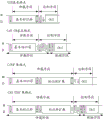
The CAN FD message consists of the same elements as the standard CAN message but different in detail. Thus, the data field and CRC field may be longer in the CAN FD message. Examples of standard CAN and CAN FD messages are shown in fig. 1.
CAN FD supports two identifier lengths of the CAN protocol, a "standard format" of 11 bits long, also called "basic format", and an "extended format" of 29 bits long. The CAN FD message has the same structure as a standard CAN message. The distinction between standard CAN messages and CAN-FD messages is made by a reserved bit, which is always explicitly transmitted in standard CAN, carries the names "r 0" and "r 1" and is located in the control field before the data length code. This bit is implicitly transmitted in the CAN FD message and is called EDL. In contrast to standard CAN messages, a control field bit, for example a BRS bit, is additionally followed in the CAN FD message, which control field bit specifies the position: at this location, the bit duration in the CAN FD message translates to a shorter value if the BRS bit has a corresponding value. This is illustrated in fig. 2 by the arrows dividing the messages into one segment with the label "CAN FD data Phase" (in which segments a high bit rate or a short bit duration is used) and two segments with the name "CAN FD Arbitration Phase" (CANFD Arbitration Phase), where a lower bit rate or a longer bit duration is used.
The number of bytes in the data field is indicated by the data length code. The code is 4 bits wide and is transmitted in the control domain. This coding is different in CAN FD than in standard CAN. The first nine codes (0 x0000 to 0x 1000) are the same, but the lower codes (0 x1001 to 0x 1111) correspond to a larger data field of the CAN FD message, for example, 12, 16, 20, 24, 32, 48 and 64 bits.
Standard CAN transceivers may be used for CAN FD, specialized transceivers are optional and may help to further increase the bit rate in the data phase when necessary.
The CAN FD protocol is described in a protocol specification with the title "CAN with Flexible Data-Rate specification" (hereinafter CAN FD specification) which is downloadable at the Website http:// www.semiconductors.bosch.de of Robert Bosch GmbH.
A hybrid network of standard CAN users and CAN FD users CAN communicate only in standard CAN format as long as an unmodified standard CAN controller is used. That is, all users in the network must have a CAN-FD protocol controller in order to perform CAN FD communication. But all CAN FD protocol controllers CAN participate in standard CAN communications.
The reason for the slower communication back into the hybrid network is the monitoring of the communication by the communication subscribers, which are jointly responsible for high transmission security, for example, in the CAN bus system. Since the unmodified standard CAN controller cannot correctly receive the faster data bits of the CAN FD message, it CAN corrupt the message by means of an Error message, a so-called Error-frame. CAN FD controller messages will be corrupted by erroneous frames in a similar way, and these messages will attempt to be transmitted after successful arbitration, for example using a bit duration again shortened with respect to the CAN FD specification or using other bit encoding or a different protocol. Thus, the transmission rate may generally be limited by one of the slower users in the network or its monitoring mechanism.
This limitation is not always necessary, in particular, if data transmission between two particular users is to be carried out using different, for example faster, communication protocols, and can be disadvantageous, in particular, if monitoring mechanisms which would lead to the destruction of different or faster messages can be dispensed with in the case of different communication protocols.
Thus, significantly higher transmission rates can be achieved, at least in certain application cases, if the monitoring mechanism causing the corrupted message by the erroneous frame is suspended by a suitable mechanism under certain assumptions.
Disclosure of Invention
The invention provides a way of eliminating the disadvantages described in that the lines of the existing bus system are used to implement a conversion to faster or otherwise modified communication without the faster transmitting messages being corrupted by other bus users.
THE ADVANTAGES OF THE PRESENT INVENTION
The invention relates to a method for exchanging data between subscribers, which are connected to one another by means of a bus system, wherein messages containing data are exchanged according to a first communication protocol, wherein the messages consist of a bit sequence, wherein at least one control bit having a predetermined position within the messages exchanged according to the first communication protocol must have a predetermined value, wherein for each message one subscriber assumes the role of a transmitter and at least one other subscriber receives the message as a receiver and performs error monitoring of the message. The method is characterized in that the transmitter transfers at least one first receiver into the protocol exception state by transmitting a control bit having a value different from the predetermined set value, so that the at least one first receiver suspends the error monitoring, wherein the transmitter starts transmitting further data to the at least one second receiver according to the second communication protocol after transmitting the control bit having the value different from the predetermined set value. Thus, control bits with different values signal: the communication on the bus line should be switched to a different, for example faster, communication protocol for which the error monitoring can be suspended. The following advantages can thus be achieved by the features according to the invention: the erroneous monitoring of the at least one receiver does not interfere with or prevent the use of the faster data transmission.
In a particularly advantageous embodiment, the values of the bits on the bus system are represented by physical signals, wherein the physical signals are used for transmission according to the second communication protocol and are different from the physical signals used for transmission according to the first communication protocol. This simplifies the separation of the communication according to the first protocol from the communication according to the second protocol on the receiver side and minimizes or avoids mutual interference of the two protocols.
Advantageously, the at least one first receiver stays in the protocol exception state until a restart condition using the first communication protocol is fulfilled. By suitable selection of the restart conditions and the second communication protocol, unintentional occurrences of the restart conditions can be prevented, so that switching back and forth between the first and second communication protocols can be made in a targeted manner.
If physical signals are used for the transmission according to the second communication protocol, which physical signals are selected such that the restart condition for using the first communication protocol is not fulfilled during the transmission according to the second communication protocol, the transmission according to the second protocol can be carried out without restrictions without the occurrence of the restart condition. A particularly advantageous configuration for this is to use physical signals for the transmission according to the second communication protocol, which are interpreted in relation to the first communication protocol as defined physical signals transmitted according to the first communication protocol that avoid the occurrence of a restart condition. It is thus ensured that the restart condition does not occur before the end of the communication according to the second communication protocol.
Furthermore, it may be advantageous to: the transmitter transmits such information after transmitting at least one control bit having a value different from a predetermined given value: according to which communication protocol the sender transmits further data, and then the sender starts transmitting further data to at least one second receiver according to the communication protocol. In particular, if the transmitter and/or the receiver are provided for using a plurality of communication protocols in addition to the first communication protocol, it can be expedient: before starting the transmission: which of these communication protocols is used for the subsequent transmission, so that the receiver can adjust this, for example, by activating a suitable receiving unit or by implementing a conversion mechanism which transmits the signals subsequently received according to the second communication protocol to a communication device suitable for this purpose.
It may be advantageous for the method that the at least one first receiver possesses the protocol exception state by performing a restart of the protocol control unit or the protocol state machine. It is also advantageous to define a predefined or predefined duration of a predefined or predefined number of bits having a predefined value or of a missing communication on the bus as a restart condition using the first communication protocol. This reduces the effort for implementing the method in these receivers, since the corresponding mechanism for performing the restart is usually always provided. In some bus systems, such as CAN, it is usual to wait for a certain number of bits with a predetermined value, in particular recessive bits, to be present in order to synchronize the existing bus communication again.
Advantageously, the message to be transmitted according to the first communication protocol has a header, a data field and a trailer, wherein the determination is made from a flag contained in the header of the message: which user gains transmit access to the bus if multiple users attempt to transmit messages simultaneously, wherein the at least one control bit is contained in the header. The access on the bus is thus retroactively allocated to the defined user for each message and no collision of messages occurs, which would lead to the destruction of two colliding messages.
If the further data are transmitted according to the second communication protocol after a suitable start signal as an arbitrary, defined sequence of data units, such as a sequence of bytes or a sequence of 16, 32 or 64 bit units, or in the UART format or in the FlexRay format or in the ethernet MAC format, the data can be transmitted quickly. Furthermore, the use of these known message formats may result in a higher security depth for the hardware and software used.
The same advantages apply analogously for a device comprising means for implementing the claimed method.
Advantageously, a predefined or predefined number of bits having a predefined value or a predefined or predefined duration of a communication that determines the absence on the bus is defined as a restart condition using the first communication protocol.
The at least one receiver can monitor the occurrence of a restart condition, in particular after a restart, using an edge recognition means and a counter for the occurrence of bits having a predetermined value, wherein the counter is restarted in the event of an edge. This further reduces the effort required for converting the method, starting from the implementation of the first communication protocol, since the user is usually synchronized in this way with the bus communication after a restart caused by an error or at the beginning of a data transmission.
Advantageously, the message to be transmitted according to the first communication protocol has a header, a data field and a trailer, wherein the data to be transmitted is contained in the data field and the at least one control bit is contained in the header. This makes it possible to acquire protocol exception states within the message after reading the control bits and, if necessary, to switch the transmitter to a different communication protocol.
If a plurality of users simultaneously attempt to transmit a message, it is advantageously ensured that no collisions occur in the bus communication, as long as the roles of transmitter and transceiver are allocated between the users by means of an arbitration method, in which it is defined from a flag contained in the header of the message which user gains transmission access to the bus. This can be achieved in particular by: the arbitration method is implemented according to CAN standard ISO 11898-1 and the header of the message comprises a start of frame bit, an arbitration field, a control field and the tail of the message has a CRC field, an acknowledgement field and an end of frame field.
A device with suitable means for carrying out the method, which method is the subject of claim 1 or its dependent claims, has corresponding advantages. Such a device can be used particularly advantageously in hybrid networks and can facilitate rapid and friction-free data transmission there.
Drawings
Fig. 1a shows the common basic structure of standard CAN and CAN-FD messages. The order and name of the message segments (start of frame bit, arbitration Field, control Field, data Field, CRC Field, acknowledgement Field (Ack Field), and end of frame Field) are illustrated. The bus is in a state of no data transfer after and before the message, which is represented by the concept "interframe space". The english name as specified in the ISO 11898 standard is commonly used. Bit Rate conversion, which CAN be done in the case of CAN FD messages, is drawn by segments with "Standard Bit Rate" and with "optional High Bit Rate".
Fig. 1b shows the headers of messages according to the standard CAN protocol and CAN FD protocol, including the start of frame bit, arbitration field and control field, in standard or basic format and in extended format, respectively. Bit rate conversion may be performed in the data phase in the case of CAN FD messages.
Fig. 2 shows a hybrid network consisting of a first user 200 and a second user 250. These subscribers are connected via a bus system 100, which may be configured, for example, as a two-wire copper wire. The wire ends may be terminated, for example, by suitable termination resistors to avoid reflections of the message. Other wire topologies, such as a ring, star or tree topology, are also contemplated. The first and second users are connected to the bus system via a first and second interface 201, 251. These interfaces include, for example, a bus connection unit such as a CAN transceiver and a communication unit such as a CAN controller or a CAN FD controller. These interfaces may also be shown wholly or partially integrated with further components of the user. A conventional combination is, for example, to integrate the communication unit into the likewise existing microprocessor of the user.
The first user appears prominent by: the first user can take possession of the protocol exception state according to the invention, while the second user appears prominent by: the second user uses the second communication protocol or is able to switch to the second communication protocol. Additional users may also be connected over the network as long as they do not interfere with the described method. Several of the users shown in fig. 2 may also be optional users, which are connected only in certain cases, for example in the case of maintenance work or in the case of programming work.
Fig. 3 schematically shows a block schematic of a first user 200 having an interface 201. The interface includes a bus connection unit 210 and a communication controller 220. The communication controller 220 includes a counter 221 and an edge recognition device 222.
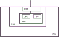
Fig. 4 illustrates a schematic block diagram of a second user 250 having an interface 251. The interface comprises a bus connection unit 260 and a communication controller 270 arranged for implementing the method according to the invention. The communication controller 270 includes a first protocol control unit 271 and a second protocol control unit 272 for this purpose. It is also possible to provide two separate communication controllers, each of which contains one of the protocol control units.
Fig. 5 shows an example of a physical signal which is transmitted by a transmitter on a bus line when transitioning from a first communication protocol to a second communication protocol using the method according to the invention and a suitable bus connection unit. The physical signals (here voltages R and D) transmitted on the bus in the first time range 410 are different from the physical signals D and M transmitted in the second time range 420.
In the following, embodiments are described in which the first user and the second user each use different communication protocols.
Detailed Description
Protocol exception status for CAN implementation tolerance with respect to CAN FD messages:
examples of protocol exception states starting from a standard CAN network are shown below with reference to fig. 2 and 3. The first subscriber 200 of the network shown in fig. 2 is in this case, for example, a control device which has a communication controller 220 with a modified standard CAN implementation as part of the interface 201. The second users of the network shown in fig. 2 are, for example, control devices which have a communication controller with a CAN FD implementation as part of the interface 251.
Implementation refers to the implementation of the communication protocol in hardware or in software, i.e. for example a CAN communication controller or an IP module which contains a CAN communication controller and CAN be integrated in a larger semiconductor component.
By modification, a standard CAN implementation, i.e. one that by definition cannot be used for sending and receiving CAN FD messages, CAN accommodate communication implemented according to a different second communication protocol. In the embodiment shown here, the different second communication protocol is CAN FD. The tolerance to different communication protocols means that this modified standard CAN implementation ignores and does not interfere with the communication operating according to the second communication protocol (in this case also CAN FD) by generating, for example, error frames. This has the advantage that: a conversion from the standard CAN protocol to the faster second protocol (i.e. CAN FD) is achieved, also in case the same bus core is used. If the restart condition using the first communication protocol (i.e. standard CAN) is fulfilled, a reverse conversion to the original standard CAN protocol takes place after the fast communication according to the second communication protocol CAN FD has ended.
The two existing functions of the CAN protocol are combined for the protocol exception state described here in order to make the standard CAN implementation thus modified tolerant to CAN FD. First, a counter 221 provided in a standard CAN implementation is used in order to detect the occurrence of 11 consecutive following recessive bits when the standard CAN implementation synchronizes to the bus communication. This takes place, for example, after a restart or when a so-called "bus disconnection recovery sequence" is executed in a standard CAN (see chapter seven "FaultConfinement", article 12 of CAN specification 2.0). Secondly, an edge detection device 222 is used which checks the input on the CAN bus side on an edge basis every CAN bus time unit in order to add the detected edge as a basis for bit synchronization. (the length of a bit in the case of a CAN bus is made up of a plurality of CAN bus Time units or "Time Quanta" of between, for example, 8 and 25, which in turn are derived from the internal oscillator clock of the respective bus subscriber.) details CAN be extracted from CAN Specification 2.0
The CAN implementation modified according to the examples described herein uses the following mechanism: the modified CAN implementation first participates in the communication as usual, i.e. it attempts to gain access to the bus within the arbitration range by sending the header of the message when there is a message to be sent. If there is no arbitration to send or the modified CAN implementation drops, the modified CAN implementation treats the bus communication as a receiver. The modified standard CAN implementation restarts its state machine (protocol state machine) responsible for protocol decoding or a protocol control unit provided for this purpose, for example a protocol control mechanism implemented in hardware, without changing its error counter and without sending error frames, directly after identifying the recessive bit at bit position r0 in the received standard CAN message having the standard format or after identifying the recessive bit at bit position r1 in the received standard CAN message having the extended format (depending on the position of the EDL bit of the CAN FD message, see fig. 1a and 1 b). In this way, the modified standard CAN implementation occupies a protocol exception state in which the modified standard CAN implementation waits for a restart condition to occur. The restart process is performed when a restart condition occurs as described further below.
Alternatively, other bits within the standard CAN message having a fixed value may also be used to introduce a protocol exception state, such as the r0 bit in the extended format, at the location of r0 in the case of the standard format or at the location of r1 in the case of the extended format.
Protocol exception status:
in the protocol exception state, a restart of the protocol state machine or the protocol control unit is first carried out. After the restart, the user waits for the sequence of 11 consecutive recessive bits in this example using a counter 221 provided for this purpose that counts bits with a predetermined value. Recessive to dominant edges are not allowed to occur within the sequence, otherwise the counter 221 restarts. This is monitored by the existing edge recognition device 222.
And (3) restarting the process:
if a restart condition, i.e. in this example a sequence of 11 consecutive recessive bits, is recognized, for example using the counter 221 and the edge recognition means 222, the user leaves the protocol exception state and is synchronized with the bus communication. The user is therefore ready again to send or receive a standard CAN message, the start of which is signaled by an explicit start-of-frame bit.
The advantage of the illustrated mechanism is thus to ensure that: the modified standard CAN user waits until a CAN FD message is transmitted (or until the CAN FD message is interrupted by an error frame when an error is identified by the CAN FD user). Since the requirement for a sequence of 11 consecutive recessive bits is never met during the transmission of a CAN FD message and the modified standard CAN user does not perform the restart procedure as it was described above. The described method thus enables this modified standard CAN implementation to tolerate all CAN FD messages.
Advantageously, the bit duration within the data phase of the CAN FD message (see fig. 2) is not shorter than the CAN bus time unit of the CAN FD arbitration phase. Otherwise, it may occur that 11 consecutive recessive bits are read out randomly in the CAN FD message by the modified standard CAN subscriber in a few cases.
Detecting CAN FD messages does not cause an increment of the error counter so that the modified standard CAN implementation CAN continue bus communication according to the standard CAN protocol directly after the end of the faster CAN FD message.
Protocol exception state for CAN FD implementation that is tolerant of modifications with respect to messages according to further developed protocols:
another example of a protocol exception condition from a CAN FD network is shown below with reference again to fig. 2 and 3. In this case, the first subscribers 200 of the network shown in fig. 2 are, for example, control devices which have devices, i.e., as shown in fig. 3 as part of the interface 201, a communication controller 220 with a modified CAN FD implementation. The second users 250 of the network shown in fig. 2 are in this example control devices which have a communication controller containing an implementation of another communication protocol as part of the interface 251. This further communication protocol may be, for example, a further development of the CAN FD protocol, which allows, for example, a longer data field than is provided in the CAN FD, depending on the content of the data length code. Furthermore, additional control bits in the control field can be envisaged, for example for data security purposes or for transmitting additional status information between users. Alternatively or additionally, the further communication protocol may set the modified calculation for the content of the CRC field and/or for different sizes of the CRC field. It is also possible to provide a plurality of communication controllers, one of which implements CAN FD communication and the second implements the further communication protocol.
The CAN FD protocol according to the disclosed specification also has bits with predetermined set values at several predetermined positions within the message. As shown in fig. 1b, the standard format and extended format CAN FD messages contain, for example, one reserved bit r1 each as the last bit in the arbitration field and a reserved bit r0 following the EDL bit in the control field.
Correspondingly, the mechanism described above for the modified standard CAN implementation applies similarly to the modified CAN FD implementation. This modified CAN FD implementation has to contain two mechanisms for this, namely the counter 221 for the 11 consecutive recessive bits in this example on the one hand and the edge recognition means 222 on the other hand. This is generally given. In other embodiments, other mechanisms for restarting communication after a restart or error recognition may be used and in turn may be used to implement the method.
The CAN FD implementation modified for the example of protocol exception state described herein now uses the following mechanism: the modified CAN FD implementation first participates in the communication as usual, that is to say it attempts to gain access to the bus within the scope of the arbitration by sending the header of the message when there is a message to be sent. The modified CAN FD implementation treats the bus communication as a receiver if there is no to-send or the modified CAN FD implementation drops arbitration. Directly after identifying the recessive bit at bit position r0 in the CAN FD message with the standard format or after identifying the recessive bit at bit position r0 in the CAN FD message with the extended format (see fig. 1a and 1 b), the modified CAN FD implementation restarts its state machine (protocol state machine) responsible for protocol decoding or a protocol control unit provided for this purpose, e.g. a protocol control mechanism implemented in hardware, without changing its error counter and without sending error frames. In this manner the modified CAN FD implementation possesses a protocol exception state in which the modified CAN FD implementation waits for a restart condition to occur. This restart condition and the restart procedure introduced thereby appear substantially the same as already described above for the first embodiment. CAN FD implementations generally have a similar mechanism, namely a counter 221 for recessive bits and an edge recognition means 222, which CAN be used in particular for this purpose.
Alternatively, other bits within the CAN FD message with fixed values may also be used to introduce protocol exception status at the location of r0 bits in the case of standard or extended format, such as r1 bits at the end of the arbitration field.
The advantages of the illustrated mechanism thus ensure that: the modified CAN FD subscriber waits until a message according to the further communication protocol is transmitted (or until the message is interrupted if necessary by a corresponding mechanism when an error is detected). The precondition is that the further communication protocol is designed such that the requirement for a sequence of 11 consecutive recessive bits is never met during transmission, and the modified CAN FD subscriber therefore does not perform a restart procedure as described above. The described method thus enables the modified CAN FD implementation to tolerate messages transmitted according to the further communication protocol.
Standard CAN or CAN FD implementations using protocol exception status for allowable modifications to protocol conversion:
the described protocol exception state can be used according to the invention for performing a protocol conversion in a hybrid network to a different communication protocol which fulfills different requirements compared to the first communication protocol. Since the first user is allowed in the protocol anomaly state, the second user can exchange or transmit data using the different communication protocol without being interfered by the first user. This is exemplarily carried out below. This example is shown from a standard CAN or CAN FD network, but the invention CAN also be shown from other networks that fulfill the features of the preamble of claim 1.
Embodiments of the invention proceeding from a standard CAN network or from a CAN FD network are now described below with reference to fig. 2, 3 and 4. In this case, the first subscriber 200 of the network shown in fig. 2 is, for example, a control device, which, as shown in fig. 3 as part of the interface 201, has a communication controller 220 with a modified standard CAN implementation or a modified CAN FD implementation. These first users are substantially different from the first users for the two previous examples of protocol exception states. A modified standard CAN implementation as well as a modified CAN FD implementation may also exist as the first user.
The second users 250 of the network shown in fig. 2 are in this further example control devices which, as part of the interface 251, have a communication controller 270 which CAN be switched according to the invention between standard CAN communication or CAN FD communication and at least one further communication protocol or communication module. Such a user is schematically shown in fig. 4. The communication controller 270 comprises a first protocol control unit 271 for the standard CAN or CAN FD protocol and a second protocol control unit 272 for the at least one further communication protocol. In an alternative embodiment of the invention, which is not shown in fig. 4, a plurality of individual communication controllers may also be provided, one of which implements standard CAN or CAN FD communication and at least one further communication controller implements one or more further communication protocols. In this case, the connection between the first and second or further communication controllers may be maintained such that the first communication controller may notify the second or further communication controller if conditions exist for using the second or further communication protocol.
If a second communication protocol is mentioned in the context of the present invention, this second communication protocol may be understood as one of the further communication protocols in the case of a plurality of further communication protocols or communication controllers.
This further communication protocol must be able to be transmitted via the bus lines provided for CAN communication and must not contain segments which, for a modified standard CAN controller or for a CAN FD controller, look like a sequence of 11 consecutive recessive bits. The further data can be transmitted after a suitable start signal as an arbitrary, defined sequence of data units, such as a sequence of bytes or a sequence of 16, 32 or 64-bit units, or in UART format or in FlexRay format or in ethernet MAC format. In principle, each communication protocol that can be represented as a sequence of voltage levels on a two-wire line and that satisfies the mentioned preconditions can be used.
If such a second user 250 according to another communication protocol wants to transmit data over the network, the second user uses the following mechanisms according to the herein described examples of the invention: the second user participates in communication according to the standard CAN or CAN FD protocol and attempts to gain access to the bus within the arbitration range by sending the header of a standard CAN or CAN FD message. This can be ensured by choosing an identifier of sufficiently low value, according to sufficiently high priority, to succeed when required. Other users of the bus communication take on the role of receivers after losing arbitration.
The second subscriber, who is the sender of the message, now sends data in the message, which results in the first subscriber being transferred into the protocol exception state. As described in the above example, this CAN be done by sending an implicit bit at bit position r0 or r1 in a CAN FD message with standard format or by sending an implicit bit at bit position r0 or r1 in a CAN FD message with extended format (see fig. 1a and 1 b). If modified standard CAN subscribers are located in the first subscriber 200, these modified CAN subscribers already possess the protocol exception state due to the recessive level of the EDL bit of the transmitted header of the CAN FD message. The CAN FD user among the first users 200 possesses a protocol exception state due to a recessive level at the position of r0 or r1 bits.
After all the first subscribers 200 have been transferred into the protocol exception state, the second subscriber, which is the sender of the message, starts the data transmission using the further communication protocol. The second user has a switchable communication controller 270 for this purpose or a switching mechanism for switching between a plurality of communication controllers provided as already implemented. The conversion can take place directly after the last bit is sent, which is necessary for forwarding the first subscriber into the protocol exception state, which bit is shown, for example, in fig. 5. The conversion can also take place with a time offset of, for example, a predefined or predefinable number of tracking bits. These tracking bits may in this case be defined in terms of bit duration or as a physical realization of the voltage difference between the bus lines according to the edge conditions of the first communication protocol. By setting such a trace bit, the following information can also be transmitted, for example, which states: according to which further communication protocol the data is transmitted after the conversion. It is particularly advantageous if the second subscriber, as sender of the message, is provided for data transmission according to a plurality of further transmission protocols.
The first user 200 remains in the protocol exception state until a restart condition occurs. A second user, who is the sender of the message, can thus send data according to a further communication protocol, which data can be received by one or more further users, as long as these users are set up for this purpose. A further second user, not the sender, receives the transmitted data according to the further communication protocol. Provision can be made for the further second subscriber to wait, like the first subscriber, for a restart condition for the communication according to the first communication protocol after the end of the data transmission according to the further communication protocol. However, the further second subscriber can also be actively converted again for communication according to the first communication protocol by means of the information contained in the transmitted data. In this case, the following conditions are assumed: during the communication with the aid of this further communication protocol, the restart condition, i.e. for example 11 consecutive recessive bit sequences, does not occur. If the communication by means of the further communication protocol is ended, the bus line remains data-free, so that a restart condition occurs and the first subscriber and the second subscriber CAN again communicate according to the standard CAN protocol or the CAN FD protocol.
The individual subscribers of the network can be set up for rapid communication in the manner shown, while the other subscribers, i.e. the first subscriber 200 of the network, only have to be changed minimally as described above. For example, a central control device or central gateway containing a large amount of software, for example for controlling communications, may exchange data with or receive data from at least one programming device, service device or input device connected for this purpose, without being disturbed by other users at the network. A plurality of control devices provided for this purpose can also exchange data or receive data from them by means of the described mechanisms with at least one programming device, service device or input device connected for this purpose. These data can be transmitted in this case successively or segment by segment successively or alternately or in parallel (for example using a plurality of mutually separable frequency bands in the further communication protocol used). Furthermore, the use of the method can be envisaged in order to additionally transmit data from messages exchanged according to the first communication protocol as data according to the second communication protocol for redundancy or encryption purposes. Thus, the determined, selected message is additionally sent in a different format for redundancy reasons or the data may be sent in association with encryption (e.g. a key or encrypted data or encryption information).
In order to ensure that a restart condition (i.e. for example 11 consecutive recessive bit sequences) does not occur during communication with the aid of a further communication protocol, the physical transport layers of the further communication protocol or of these further communication protocols can also be adapted with respect to the transport layers of the first communication protocol:
for this purpose, for example, a new type of transceiver 260 can be used, which is configured in such a way that, in addition to the physical signals of the first communication protocol, it can also generate and determine further physical signals of at least one further communication protocol, which are configured in such a way that a response to a restart condition is effectively avoided. This can be achieved, for example, by using physical signals such as differential voltage levels for the transmission according to the second communication protocol, which are interpreted with respect to the first communication protocol (i.e., for example in a communication controller provided for the first communication protocol) as determined physical signals of the transmission according to the first communication protocol, which avoid the occurrence of a restart condition. If, as described above, the restart condition is defined as a predefined or predefinable number of bits having a predefined value, for example consecutive recessive bits, the transmission according to the second communication protocol can use, for example, physical signals which are interpreted with respect to the first communication protocol as bits which differ from this, i.e. for example as dominant bits. This is further elucidated in the following example with respect to fig. 5.
For example, starting from a conventional CAN transceiver, it is possible to introduce: the novel transceiver knows not only the two "recessive" and "dominant" levels known to the CAN, but also at least one additional level (e.g., "maximum"), for example:
-recessive level R: the transceiver of the transmitter does not drive current. The voltage difference between the bus lines is, for example, 0 volt.
-a dominant level D: the transceiver of the transmitter drives the current by means of a suitable means, such as a current source, so that a standard CAN voltage difference occurs. The voltage difference between the bus lines is, for example, 2 volts.
-maximum level M: the transceiver of the transmitter drives a stronger current by means of suitable means, such as a current source, so that a higher voltage difference occurs. The voltage difference between the bus lines is for example 4 volts.
The first two levels are identified as recessive R or dominant D by all participating standard CAN, CAN FD and new transceivers. This third level is recognized by all conventional CAN and CAN FD transceivers as dominant D and by the new transceiver as maximum M.
Fig. 5 shows examples of physical signals that can be generated on a bus line by the novel transceiver of the transmitter when transitioning from the first to the second communication protocol. Communication according to a first communication protocol takes place in a first segment 410. The physical signal is a differential voltage value of 0 volts or 2 volts depending on the recessive level R or the dominant level D. Communication according to the second communication protocol takes place in the second segment 420. The physical signal is a difference voltage value of 2 volts or 4 volts depending on the maximum level M or the dominant level D.
The new model transceiver 260 has, for example, an additional output connected to a communication controller modified according to the invention or, if necessary, to a further communication controller implementing one or more further communication protocols. For example, "Universal Asynchronous Receiver Transmitter" (UART) or FlexRay may be used as protocol, but in principle every other serial transmission protocol, for example also the ethernet MAC format, may also be used. Depending on whether the bus level is determined to be "maximum" M or "dominant" D, different logic signals are passed to the communication controller. So that if the second subscriber, acting as a sender of the message, transfers the first subscriber 200 into the protocol exception state, it then only transmits in both the "maximum" and "dominant" levels. Thus, a standard CAN or CAN FD controller always determines only one dominant bus level at the receive output of the transceiver. As long as data is transmitted in this way, the restart condition of 11 consecutive following recessive bits does not occur. Therefore, there is no restriction in the possible transmitted data formats of the second communication protocol. Naturally, a number of additional levels such as "max 1" and "max 2" etc. may also be determined. As long as the new type of transceiver is able to reliably distinguish between the levels, a corresponding code with multiple levels may be used for transmission. Corresponding methods are known, for example, from ethernet networks.
The described transition between the at least two driven levels "dominant" D and "maximum" M has the further advantage: the transmitted bit can be transmitted with a shorter bit duration, since the steepness of the edges no longer depends on how the voltage level is adjusted by the termination resistance.
The bus users only need to be equipped with new types of transceivers using additional communication protocols. The remaining bus users may use conventional transceivers. Instead of switching between the dominant "level" and the "maximum" level, it is also possible to keep the CAN bus at the dominant level and to modulate the ASC data by suitable means.
Claims (16)
1. Method for exchanging data between subscribers, which are connected to one another by means of a bus system,
wherein messages containing data are exchanged according to a first communication protocol,
wherein the message is composed of a sequence of bits,
wherein at least one control bit having a predetermined position within the messages exchanged according to the first communication protocol must have a predetermined value,
wherein for each message one user takes the role of sender and at least another user receives the message as receiver and performs error monitoring for the message,
it is characterized in that the preparation method is characterized in that,
forwarding at least one first receiver into a protocol exception state by sending a control bit having a value different from a predetermined set value, such that the at least one first receiver suspends error monitoring,
wherein the transmitter starts transmitting further data according to the second communication protocol to the at least one second receiver after transmitting the control bits having a value different from the predetermined value.
2. The method of claim 1, wherein the first and second light sources are selected from the group consisting of,
it is characterized in that the preparation method is characterized in that,
the value of a bit on the bus system is represented by a physical signal, wherein the physical signal is used for transmission according to the second communication protocol, which is different from the physical signal used for transmission according to the first communication protocol.
3. The method according to claim 1 or 2,
it is characterized in that the preparation method is characterized in that,
the at least one first receiver stays in the protocol exception state until a restart condition using the first communication protocol is satisfied.
4. The method of claim 3, wherein the first and second light sources are selected from the group consisting of,
it is characterized in that the preparation method is characterized in that,
the physical signal is used for transmission according to the second communication protocol, the physical signal being chosen such that a restart condition using the first communication protocol is not fulfilled during transmission according to the second communication protocol.
5. The method of claim 3, wherein the first and second light sources are selected from the group consisting of,
it is characterized in that the preparation method is characterized in that,
the following physical signals are used for the transmission according to the second communication protocol, which are interpreted with respect to the first communication protocol as physical signals determined for the transmission according to the first communication protocol avoiding the occurrence of a restart condition.
6. The method according to claim 1 or 2,
it is characterized in that the preparation method is characterized in that,
the transmitter transmits such information after transmitting at least one control bit having a value different from a predetermined given value: according to which communication protocol the transmitter transmits the further data, and then the transmitter starts transmitting the further data according to the communication protocol.
7. The method according to claim 1 or 2,
it is characterized in that the preparation method is characterized in that,
at least one receiver possesses a protocol exception state by performing a restart of a protocol control unit or a protocol state machine.
8. The method of claim 3, wherein the first and second light sources are selected from the group consisting of,
it is characterized in that the preparation method is characterized in that,
a predetermined number of bits having a predetermined value are defined as a restart condition for using the first communication protocol.
9. The method of claim 3, wherein the first and second light sources are selected from the group consisting of,
it is characterized in that the preparation method is characterized in that,
a predefined duration of the missing communication on the bus is defined as a restart condition using the first communication protocol.
10. The method according to claim 1 or 2,
it is characterized in that the preparation method is characterized in that,
a message to be transmitted according to the first communication protocol has a header, a data field and a trailer,
wherein it is determined from a flag contained in a header of the message: if multiple users attempt to send messages at the same time, which user gains send access to the bus,
wherein at least one control bit is contained in the header.
11. The method according to claim 1 or 2,
it is characterized in that the preparation method is characterized in that,
the further data are transmitted according to the second communication protocol after the start signal as an arbitrary, defined sequence of data units or in UART format or in FlexRay format or in ethernet MAC format.
12. The method according to claim 1 or 2,
it is characterized in that the preparation method is characterized in that,
the further data are transmitted in parallel to a plurality of receivers using a plurality of mutually separable frequency bands according to a second communication protocol.
13. The method according to claim 1 or 2,
it is characterized in that the preparation method is characterized in that,
by means of the method, data in messages exchanged according to the first communication protocol is additionally transmitted as data according to the second communication protocol for redundancy or encryption purposes.
14. Device for exchanging data between subscribers, which are connected to one another by means of a bus system,
the apparatus has means for causing messages containing data to be exchanged according to a first communication protocol,
wherein the message is composed of a sequence of bits,
wherein at least one control bit having a predetermined position within the messages exchanged according to the first communication protocol must have a predetermined value,
it is characterized in that the preparation method is characterized in that,
wherein the device has means for forwarding at least one first receiver into a protocol exception state by sending a control bit having a value different from a predetermined given value, such that said at least one first receiver suspends error monitoring until a restart condition for its use of the first communication protocol is fulfilled,
wherein the occurrence of a predetermined number of consecutive recessive bits is defined as a restart condition,
wherein the apparatus comprises means for transmitting further data according to a second communication protocol in the presence of control bits having a value different from a predetermined value,
wherein the restart condition for using the first communication protocol is not satisfied during the transmission according to the second communication protocol, thereby ensuring that the at least one first receiver waits in the protocol exception state until a message according to the second communication protocol is transmitted.
15. The apparatus as set forth in claim 14, wherein,
it is characterized in that the preparation method is characterized in that,
the device has means for receiving as a receiver further data according to a second communication protocol upon receiving a control bit having a value different from a predetermined value.
16. The apparatus of claim 14 or 15,
it is characterized in that the preparation method is characterized in that,
the device has means for transmitting such information after sending control bits having a value different from a predetermined given value: depending on which second communication protocol the further data is transmitted.
Applications Claiming Priority (3)
| Application Number | Priority Date | Filing Date | Title |
|---|---|---|---|
| DE201210224024 DE102012224024A1 (en) | 2012-12-20 | 2012-12-20 | Data transfer using a log exemption state |
| DE102012224024.1 | 2012-12-20 | ||
| PCT/EP2013/077515 WO2014096272A1 (en) | 2012-12-20 | 2013-12-19 | Data transmission using a protocol exception state |
Publications (2)
| Publication Number | Publication Date |
|---|---|
| CN104995873A CN104995873A (en) | 2015-10-21 |
| CN104995873B true CN104995873B (en) | 2020-01-21 |
Family
ID=49886915
Family Applications (1)
| Application Number | Title | Priority Date | Filing Date |
|---|---|---|---|
| CN201380073328.XA Active CN104995873B (en) | 2012-12-20 | 2013-12-19 | Data transmission using protocol exception state |
Country Status (9)
| Country | Link |
|---|---|
| US (1) | US9740655B2 (en) |
| EP (1) | EP2936747B1 (en) |
| JP (1) | JP6093031B2 (en) |
| KR (1) | KR102190750B1 (en) |
| CN (1) | CN104995873B (en) |
| BR (1) | BR112015014861B1 (en) |
| DE (1) | DE102012224024A1 (en) |
| ES (1) | ES2742900T3 (en) |
| WO (1) | WO2014096272A1 (en) |
Families Citing this family (36)
| Publication number | Priority date | Publication date | Assignee | Title |
|---|---|---|---|---|
| US9652423B2 (en) * | 2013-06-05 | 2017-05-16 | Texas Instruments Incorporated | CAN and flexible data rate CAN node apparatus and methods for mixed bus CAN FD communications |
| DE102014210505A1 (en) * | 2014-06-03 | 2015-12-03 | Robert Bosch Gmbh | Transmission unit with test function |
| KR101519793B1 (en) * | 2014-06-24 | 2015-05-12 | 현대자동차주식회사 | Network system for vehicle and data transmission method of a different kind communication controller in the same system |
| CN107637023B (en) * | 2015-03-26 | 2021-01-22 | 大陆-特韦斯贸易合伙股份公司及两合公司 | Method for transmitting messages in a data bus system, transceiver and electronic control unit for a motor vehicle |
| US11016925B2 (en) | 2015-03-26 | 2021-05-25 | Nxp Usa, Inc. | Protocol-tolerant communications in controller area networks |
| CN107709209B (en) * | 2015-06-15 | 2019-09-17 | 三菱电机株式会社 | Elevator safety system |
| JP6520729B2 (en) * | 2016-01-19 | 2019-05-29 | 株式会社デンソー | Communication device |
| KR102594508B1 (en) * | 2016-06-17 | 2023-10-27 | 주식회사 에이치엘클레무브 | Apparatus and Method thereof Gateway |
| DE102016216898A1 (en) * | 2016-09-06 | 2018-03-08 | Continental Automotive Gmbh | Test device and method for checking a behavior of a network network from control units of a motor vehicle in the case of faulty and / or manipulated network data traffic |
| JP2018082247A (en) * | 2016-11-14 | 2018-05-24 | 株式会社東芝 | Communication device, communication system, communication method, and program |
| JP6743724B2 (en) * | 2017-02-22 | 2020-08-19 | 株式会社デンソー | Communication network and communication terminal |
| DE102017208553A1 (en) * | 2017-05-19 | 2018-11-22 | Robert Bosch Gmbh | Method for protecting a network from cyber attack |
| DE102017012214B4 (en) * | 2017-07-11 | 2019-06-19 | Volkswagen Aktiengesellschaft | Method for transmitting data via a serial communication bus, appropriately designed bus interface and computer program designed accordingly |
| DE102017211860B3 (en) | 2017-07-11 | 2018-09-20 | Volkswagen Aktiengesellschaft | Method for transmitting data via a serial communication bus, appropriately designed bus interface and computer program designed accordingly |
| DE102017212757A1 (en) * | 2017-07-25 | 2019-01-31 | Robert Bosch Gmbh | Method and device for protecting a fieldbus |
| EP3665875B1 (en) | 2017-08-08 | 2022-03-16 | Volkswagen Aktiengesellschaft | Method for transmitting data via a serial communication bus, correspondingly designed bus interface, and correspondingly designed computer program |
| DE102018202168A1 (en) * | 2017-12-22 | 2019-06-27 | Robert Bosch Gmbh | Subscriber station for a serial bus system and method for sending a message in a serial bus system |
| DE102017223775A1 (en) * | 2017-12-22 | 2019-06-27 | Robert Bosch Gmbh | Subscriber station for a bus system and method for sending a message with different bit rates in a bus system |
| KR20190103739A (en) | 2018-02-28 | 2019-09-05 | 박용태 | Shade device for ginseng cultivation |
| DE102018110252A1 (en) * | 2018-04-27 | 2019-10-31 | Infineon Technologies Ag | Transceiver, system with transceivers and signal |
| CN108957237B (en) * | 2018-08-01 | 2020-12-01 | 歌尔光学科技有限公司 | Abnormal line detection method, device, equipment and storage medium |
| DE102019200289A1 (en) * | 2018-08-17 | 2020-02-20 | Robert Bosch Gmbh | Frame shielding unit, subscriber station for a serial bus system and method for communication in a serial bus system |
| DE102018218721A1 (en) * | 2018-10-31 | 2020-04-30 | Robert Bosch Gmbh | Subscriber station for a serial bus system and method for sending a message in a serial bus system |
| DE102018218720A1 (en) | 2018-10-31 | 2020-04-30 | Robert Bosch Gmbh | Subscriber station for a serial bus system and method for sending a message in a serial bus system |
| CN109445718A (en) * | 2018-11-16 | 2019-03-08 | 广东小天才科技有限公司 | A kind of method for writing data and system based on Data Migration |
| EP3700138B1 (en) * | 2019-02-22 | 2023-08-02 | Volvo Car Corporation | Monitoring lin nodes |
| EP3745656B1 (en) * | 2019-05-29 | 2023-08-09 | Nxp B.V. | Controller area network transceiver |
| US11423247B2 (en) * | 2019-06-13 | 2022-08-23 | Sri International | Identifying fixed bits of a bitstring format |
| DE102019213322A1 (en) * | 2019-09-03 | 2021-03-04 | Continental Automotive Gmbh | Ethernet physical layer transceiver for two-wire bus topology |
| DE102019125693A1 (en) * | 2019-09-24 | 2021-03-25 | Beckhoff Automation Gmbh | Method for operating a communication network, communication network and subscriber for a communication network |
| DE102019218715A1 (en) * | 2019-12-02 | 2021-06-02 | Robert Bosch Gmbh | Subscriber station for a serial bus system and method for communication in a serial bus system |
| US11539714B2 (en) | 2020-09-17 | 2022-12-27 | Ford Global Technologies, Llc | Assigning categories for messages and symmetric key per category to localize the impact in case of key compromise |
| US11381421B2 (en) | 2020-09-17 | 2022-07-05 | Ford Global Technologies, Llc | Using signal rating to identify security critical CAN messages and nodes for efficient implementation of distributed network security features |
| DE102022208383A1 (en) | 2022-08-11 | 2024-02-22 | Robert Bosch Gesellschaft mit beschränkter Haftung | Method for carrying out a data transfer |
| DE102022208902A1 (en) | 2022-08-29 | 2024-02-29 | Continental Automotive Technologies GmbH | Method for sending data and bus nodes |
| DE102022208901A1 (en) | 2022-08-29 | 2024-02-29 | Continental Automotive Technologies GmbH | Method for sending and receiving data, transmitter and receiver |
Citations (4)
| Publication number | Priority date | Publication date | Assignee | Title |
|---|---|---|---|---|
| JPH031742A (en) * | 1989-05-30 | 1991-01-08 | Konica Corp | Transmission speed automatic selection device |
| JPH09116988A (en) * | 1995-10-18 | 1997-05-02 | Fujitsu Ten Ltd | In-vehicle communication method |
| CN102195753A (en) * | 2010-12-09 | 2011-09-21 | 无锡乐智科技有限公司 | 2.4G-radio-frequency (2.4GRF)-based multimedia transmission method |
| WO2012136547A1 (en) * | 2011-04-06 | 2012-10-11 | Robert Bosch Gmbh | Method and device for increasing the data transmission capacity in a serial bus system |
Family Cites Families (14)
| Publication number | Priority date | Publication date | Assignee | Title |
|---|---|---|---|---|
| DE4129205A1 (en) * | 1991-03-28 | 1992-10-01 | Bosch Gmbh Robert | METHOD FOR BUILDING MESSAGES FOR DATA EXCHANGE AND / OR FOR SYNCHRONIZING PROCESSES IN DATA PROCESSING SYSTEMS |
| US5854454A (en) * | 1996-09-16 | 1998-12-29 | Otis Elevator Company | Message routing in control area network (CAN) protocol |
| US6104726A (en) * | 1997-03-31 | 2000-08-15 | Motorola, Inc. | Simultaneous transfer of voice and data information using multi-rate vocoder and bit control protocol |
| US20020112109A1 (en) * | 2001-02-14 | 2002-08-15 | Jorgenson Anthony William | Method and apparatus for providing full duplex/half duplex radially distributed serial control bus architecture |
| DE102005061392A1 (en) * | 2005-12-22 | 2007-06-28 | Robert Bosch Gmbh | Bus guardian for monitoring and controlling access to data bus, has serial peripheral interface approving access of controller to data bus only when communication offers normal functioning of controller |
| US7627800B2 (en) * | 2006-05-22 | 2009-12-01 | International Business Machines Corporation | Communicating with error checking to a device capable of operating according to an address prefix serial bus protocol |
| JP2008061223A (en) * | 2006-08-04 | 2008-03-13 | Canon Inc | Communication apparatus and communication control method |
| DE102007028766A1 (en) * | 2007-06-22 | 2008-12-24 | Continental Teves Ag & Co. Ohg | Test method and electronic circuit for the secure serial transmission of data |
| DE102007051657A1 (en) * | 2007-10-26 | 2009-04-30 | Robert Bosch Gmbh | Communication system with a CAN bus and method for operating such a communication system |
| JP5308802B2 (en) * | 2008-12-16 | 2013-10-09 | ルネサスエレクトロニクス株式会社 | CAN node |
| KR20100073846A (en) * | 2008-12-23 | 2010-07-01 | 한국전자통신연구원 | Data frame transmissing and receiving method in a can protocol |
| JP2010258990A (en) * | 2009-04-28 | 2010-11-11 | Autonetworks Technologies Ltd | Control system and control program updating method |
| DE102011089587A1 (en) * | 2011-12-22 | 2013-06-27 | Robert Bosch Gmbh | Subscriber station of a bus system and method for transmitting messages between subscriber stations of a bus system |
| EP2712123A1 (en) * | 2012-09-20 | 2014-03-26 | Robert Bosch Gmbh | Standard CAN implementation tolerating CAN FD frames |
-
2012
- 2012-12-20 DE DE201210224024 patent/DE102012224024A1/en active Pending
-
2013
- 2013-12-19 CN CN201380073328.XA patent/CN104995873B/en active Active
- 2013-12-19 JP JP2015548600A patent/JP6093031B2/en active Active
- 2013-12-19 BR BR112015014861-1A patent/BR112015014861B1/en active IP Right Grant
- 2013-12-19 US US14/652,743 patent/US9740655B2/en active Active
- 2013-12-19 EP EP13814919.0A patent/EP2936747B1/en active Active
- 2013-12-19 WO PCT/EP2013/077515 patent/WO2014096272A1/en active Application Filing
- 2013-12-19 KR KR1020157019543A patent/KR102190750B1/en active IP Right Grant
- 2013-12-19 ES ES13814919T patent/ES2742900T3/en active Active
Patent Citations (4)
| Publication number | Priority date | Publication date | Assignee | Title |
|---|---|---|---|---|
| JPH031742A (en) * | 1989-05-30 | 1991-01-08 | Konica Corp | Transmission speed automatic selection device |
| JPH09116988A (en) * | 1995-10-18 | 1997-05-02 | Fujitsu Ten Ltd | In-vehicle communication method |
| CN102195753A (en) * | 2010-12-09 | 2011-09-21 | 无锡乐智科技有限公司 | 2.4G-radio-frequency (2.4GRF)-based multimedia transmission method |
| WO2012136547A1 (en) * | 2011-04-06 | 2012-10-11 | Robert Bosch Gmbh | Method and device for increasing the data transmission capacity in a serial bus system |
Also Published As
| Publication number | Publication date |
|---|---|
| EP2936747A1 (en) | 2015-10-28 |
| DE102012224024A1 (en) | 2014-06-26 |
| JP6093031B2 (en) | 2017-03-08 |
| EP2936747B1 (en) | 2019-05-22 |
| ES2742900T3 (en) | 2020-02-17 |
| CN104995873A (en) | 2015-10-21 |
| JP2016504873A (en) | 2016-02-12 |
| US9740655B2 (en) | 2017-08-22 |
| KR102190750B1 (en) | 2020-12-15 |
| WO2014096272A1 (en) | 2014-06-26 |
| KR20150100790A (en) | 2015-09-02 |
| BR112015014861B1 (en) | 2022-09-06 |
| BR112015014861A2 (en) | 2017-07-11 |
| US20150339254A1 (en) | 2015-11-26 |
Similar Documents
| Publication | Publication Date | Title |
|---|---|---|
| CN104995873B (en) | Data transmission using protocol exception state | |
| US9742584B2 (en) | Controller area network with flexible data-rate | |
| EP2521319B1 (en) | Controller area network with flexible data-rate | |
| JP7200374B2 (en) | Error frame shielding unit for subscriber station of serial bus system and communication method in serial bus system | |
| JP6121563B2 (en) | Data transmission protocol using protocol exception state | |
| CN113330719B (en) | Subscriber station for a serial bus system and method for communication in a serial bus system | |
| US10776307B2 (en) | Subscriber station for a serial bus system, and method for transmitting a message in a serial bus system | |
| US11831465B2 (en) | Overlap detection unit for a user station of a serial bus system, and method for communicating in a serial bus system | |
| CN113841362B (en) | Subscriber station for a serial bus system and method for communication in a serial bus system | |
| KR102366436B1 (en) | Transmission unit with checking function | |
| CN112823496B (en) | Frame masking unit, subscriber station for a serial bus system and method for communication in a serial bus system | |
| US11831466B2 (en) | User station for a serial bus system, and method for transmitting a message in a serial bus system | |
| CN111713074B (en) | Subscriber station for a serial bus system and method for signaling errors for messages received in a serial bus system | |
| CN113645111A (en) | Communication control device, transmission/reception device, and communication method in bus system | |
| CN114930775A (en) | Transmitting/receiving device and communication control device for a subscriber station of a serial bus system and method for communication in a serial bus system |
Legal Events
| Date | Code | Title | Description |
|---|---|---|---|
| C06 | Publication | ||
| PB01 | Publication | ||
| C10 | Entry into substantive examination | ||
| SE01 | Entry into force of request for substantive examination | ||
| GR01 | Patent grant | ||
| GR01 | Patent grant |