CN1047237A - Friction welding (FW) - Google Patents
Friction welding (FW) Download PDFInfo
- Publication number
- CN1047237A CN1047237A CN90104261A CN90104261A CN1047237A CN 1047237 A CN1047237 A CN 1047237A CN 90104261 A CN90104261 A CN 90104261A CN 90104261 A CN90104261 A CN 90104261A CN 1047237 A CN1047237 A CN 1047237A
- Authority
- CN
- China
- Prior art keywords
- workpiece
- work holder
- welding
- motion
- unit
- Prior art date
- Legal status (The legal status is an assumption and is not a legal conclusion. Google has not performed a legal analysis and makes no representation as to the accuracy of the status listed.)
- Pending
Links
Images


Classifications
-
- B—PERFORMING OPERATIONS; TRANSPORTING
- B29—WORKING OF PLASTICS; WORKING OF SUBSTANCES IN A PLASTIC STATE IN GENERAL
- B29C—SHAPING OR JOINING OF PLASTICS; SHAPING OF MATERIAL IN A PLASTIC STATE, NOT OTHERWISE PROVIDED FOR; AFTER-TREATMENT OF THE SHAPED PRODUCTS, e.g. REPAIRING
- B29C65/00—Joining or sealing of preformed parts, e.g. welding of plastics materials; Apparatus therefor
- B29C65/02—Joining or sealing of preformed parts, e.g. welding of plastics materials; Apparatus therefor by heating, with or without pressure
- B29C65/06—Joining or sealing of preformed parts, e.g. welding of plastics materials; Apparatus therefor by heating, with or without pressure using friction, e.g. spin welding
-
- B—PERFORMING OPERATIONS; TRANSPORTING
- B23—MACHINE TOOLS; METAL-WORKING NOT OTHERWISE PROVIDED FOR
- B23K—SOLDERING OR UNSOLDERING; WELDING; CLADDING OR PLATING BY SOLDERING OR WELDING; CUTTING BY APPLYING HEAT LOCALLY, e.g. FLAME CUTTING; WORKING BY LASER BEAM
- B23K20/00—Non-electric welding by applying impact or other pressure, with or without the application of heat, e.g. cladding or plating
- B23K20/12—Non-electric welding by applying impact or other pressure, with or without the application of heat, e.g. cladding or plating the heat being generated by friction; Friction welding
- B23K20/1205—Non-electric welding by applying impact or other pressure, with or without the application of heat, e.g. cladding or plating the heat being generated by friction; Friction welding using translation movement
-
- B—PERFORMING OPERATIONS; TRANSPORTING
- B23—MACHINE TOOLS; METAL-WORKING NOT OTHERWISE PROVIDED FOR
- B23K—SOLDERING OR UNSOLDERING; WELDING; CLADDING OR PLATING BY SOLDERING OR WELDING; CUTTING BY APPLYING HEAT LOCALLY, e.g. FLAME CUTTING; WORKING BY LASER BEAM
- B23K2101/00—Articles made by soldering, welding or cutting
- B23K2101/001—Turbines
Abstract
With friction welding (FW) unit one is soldered to second equipment on the workpiece, comprises being used to produce reciprocating drive unit; A work holder that is used for the clamping unit one; Be used for reciprocating motion is sent to work holder from drive unit, thereby make unit one realize producing the jockey of warm-up movement; Thereby pressure is applied to the pressure apparatus that also makes unit one realize the welding motion on the work holder, and during friction welding (FW), jockey (4) can adapt to welding motion needs, and pressure apparatus can adapt to the needs that produce warm-up movement.A releasing device in order to work holder is discharged from drive unit, and can make work holder back off from the workpiece that has welded.
Description
The present invention relates to friction welding (FW), particularly a kind of reciprocating type friction welding (FW).When carrying out reciprocating type friction welding (FW), two workpiece that will be welded together are put together, make a face of one of them workpiece be fitted on the face of another workpiece, produce corresponding the reciprocating motion between two workpiece, because the opposite face of two workpiece forces together, and has produced frictional heat, when near the temperature the phase pressure surface reaches a sufficiently high value, the corresponding sports that produces heat between two workpiece stops, and two workpiece are welded together.
The mutual binding face of workpiece is the plane normally, but how the shape on surface is not main, as long as can produce reciprocating motion between them, and when moving back and forth, binding face can not be separated from each other.
During heat produces, the workpiece material deliquescing of contiguous binding face, because workpiece is pressed together, the material of some deliquescing is pressed towards the next door, consequently workpiece little by little shifts near mutually.After the corresponding sports that produces heat between workpiece stops, this moving the time that can also continue a weak point, in the meantime, temperature descends, because workpiece just is being welded in together, be retained in the material of any deliquescing between workpiece or be pressed towards the next door or curing, the corresponding sports that workpiece is tended to together gradually is known as the welding motion hereinafter, is called the motion that produces heat hereinafter in order to the corresponding sports that produces frictional heat simultaneously.Be to be understood that simultaneously, the welding travel direction take place perpendicular to producing the heat travel direction.
When adopting reciprocating type friction welding (FW) to come the weld metal workpiece, usually need to use sizable power.In order to simplify these used power, normally arrange a workpiece to carry out the motion of all generation heats in the practice, and another workpiece is used for carrying out all welding campaigns, but this will cause some problems, and purpose of the present invention helps to overcome or reduces these problems at least.
First aspect of the present invention is to comprise that one is soldered to second equipment on the workpiece with the unit one friction.This equipment comprises to produce reciprocating drive unit; A work holder that is used for the clamping unit one; Reciprocating motion with drive unit output is sent on the work holder, thereby makes unit one carry out the jockey of reciprocating type generation warm-up movement; One is applied to pressure on the work holder, thereby makes first workpiece also weld the pressure apparatus of motion; Jockey is such, during friction welding (FW), can cooperate the welding motion, and pressure apparatus is such, during friction welding (FW), can cooperate the motion that produces heat.
This equipment preferably further comprises releasing device, after friction welding (FW), work holder can be thrown off from drive unit, and work holder is backed off from the workpiece that welds.
Jockey comprises a hinge bar at least, and during friction welding (FW), this connecting rod can cooperate the welding campaign of work holder.Yet,, during producing warm-up movement, be necessary to make connecting rod that a preload value that is enough to avoid producing backlash is arranged if adopt such hinge bar.In order to cancel above-mentioned preload requirement, jockey comprises at least that preferably an energy bending to adapt to the bendable member of welding motion, preferably has a plurality of bendable member, and these parts comprise can be at any bar or rod that laterally carries out same bending.Yet these parts preferably comprise flexible blade, and it is in transverse curvature, and are rigidity on perpendicular to horizontal direction.
When releasing device is provided, preferably work holder and drive unit are separated.Action is separately taking place on a desired location of jockey, preferably at the parts of work holder and jockey (as one or more hinge bars, or one or more bendable member) take place between, during friction welding (FW), these parts can cooperate the welding campaign of work holder.
Work holder is the clamping unit one directly, but, preferably work holder with one successively the anchor clamps of holding workpiece combine, conversion by means of anchor clamps, under different occasions, just can adopt same work holder to come the workpiece of clamping difformity and size.
Pressure apparatus preferably includes oil cylinder mechanism, is used for power is applied on the non-reciprocating pressure head, produces the flexible jockey of warm-up movement by making work holder, and non-reciprocating pressure head is linked on the work holder.Jockey can comprise one or more hinge bars, but preferably includes one or more bendable member.These bendable member can comprise flexible bar or rod.But preferably include flexible blade, and its orientation is such, on the direction of generation warm-up movement, moves perpendicular to it to prevent work holder.Preferably stop the motion of reciprocal pressure head of the vibration-direction of the generation heat that is parallel to work holder, and guiding device can make still pressure head and work holder weld motion with guiding device.Guiding device preferably constitutes with the backlash in preventing to use by the drum apparatus of preload and bounces.
Second aspect of the present invention is the equipment of using according to first aspect of the present invention, and first and second workpiece are welded together.
Third aspect of the present invention is the method for a friction welding (FW), at welding bench, by means of reciprocating type friction welding (FW), unit one and second workpiece is welded together.Unit one can carry out the motion of necessary reciprocating type generation heat, also can carry out necessary welding campaign.Second the unit one mass motion of workpiece on being welded to it, and on welding bench, under reciprocating type friction welding (FW) effect, the 3rd workpiece is soldered on second workpiece, the 3rd workpiece can carry out the motion of necessary generation heat, also can carry out necessary welding campaign.
Similarly, other workpiece can in turn be friction welded on second workpiece, and on welding bench, before next workpiece was welded on second workpiece, second workpiece can be with the workpiece mass motion together of welding thereon.
Friction welding (FW) preferably carries out under the help according to the equipment of first aspect of the present invention.
The mass motion of second workpiece preferably includes rotatablely moving of second workpiece.
The 4th aspect of the present invention is that the method by means of third aspect of the present invention welds together workpiece.
Below with reference to accompanying drawings, only by way of example mode embodiments of the invention are described.
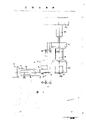
Fig. 1 schematically expresses the side view of part first friction welding apparatus of first aspect present invention,
Fig. 2 schematically expresses the side view that whole friction welding apparatus shown in Figure 1 is drawn by the small scale size.
Fig. 3 looks from Fig. 2 the right, illustrates the end-view of equipment,
Fig. 4 is the simple and easy plan view in conjunction with a device of Fig. 1-3 equipment,
Fig. 5 is the simplified side view that is welded to epitrochanterian turbo blade inside,,
Fig. 6 is the side view that is used for replacing the alternate form support of the support of Fig. 2 to draw by the small scale size,
Fig. 7 is the side view of second friction welding apparatus of the present invention, for represent clear for the purpose of, some parts is analysed and observe,
Fig. 8 is the front view of Fig. 7 equipment,
Fig. 9 is the plan view of Fig. 7 equipment.
Equipment shown in Fig. 1-6 is used for carrying out reciprocating type friction welding (FW), and this equipment comprises that one makes output 2 at the reciprocating drive unit 1 of horizontal plane.Drive unit can be a kind of at British Patent No. 2199783(Allwood, Searle ﹠amp; Timney(Holdings) the sort of equipment of describing and illustrating in specification Limited).The rotating shaft of drive unit is represented with 3.The jockey 4 that is fixed firmly to the output jag comprises a metal bar, and this excellent center is processed to be fallen, and stays a pair of flexible metal blade 5.One connects the other end that socket 6 is fixed firmly to jockey 4, the locating slot that while socket 6 has an opening to make progress, and this groove has angled side walls.One coupling head 7 enters this groove from the top, and coupling head 7 has the angled side walls that matches with locating slot.With cap screw 8 coupling head 7 can be fixed on the connection socket with loosening.Coupling head 7 integrally is connected with the long rod 9 of a level, and this rod integrally is connected with work holder 10 again.The downward open hole that has a band upright side walls on the work holder 10.This through hole entangles the anchor clamps 11 that a location will be welded in unit one together.Not shown this workpiece in Fig. 1, but figure 2 illustrates the profile of the turbo blade 12 that constitutes unit one.
Be fixed firmly to the downside that a pair of flexible metal blade 13 on work holder 10 tops upwards directly reaches pressure head 14, and firmly be fixed on the pressure head 14, a hydraulic jack 15 of vertically installing is arranged on the pressure head, it is in 16 actions of fixture of pressure head and equipment, pressure head is fixed on the upper part of a vertical long guide rod 17, and long guide rod 17 is between heavily loaded roller 18, and this set makes long guide rod 17 only in lengthwise movement.Be contained in nut rotor 19 on the guide rod 17 and have the power transmission head of a polygonal cross-section, this driving head from rotor 19 times side-prominent and can with cap screw 8 engagements so that they rotate on arbitrary direction of rotation.The nut rotor of being adorned is used for lengthwise movement on guide rod, so it can move between the upper and lower, top is the unengaged position that it separates from cap screw, and the bottom is the bonding station that meshes with cap screw.Suitable Power Drive Unit is used for making the nut rotor to come and go between needed position on the guide rod.
The operational circumstances of the equipment component shown in Fig. 1-2 will be described below.Initial in operation, drive unit does not drive reciprocal output 2, and at this moment, output is positioned at the center, promptly is positioned on half position between its level run restriction.Nut rotor 19 is lowered to its position of engagement, but does not screw cap screw 8, thereby coupling head no longer is fixed on the connection socket.Then, handle oil cylinder 15, to promote pressure head 14, blade 13 and to have the work holder 10 of rod 9 and coupling head 7.First workpiece that will weld (as turbo blade) installs in the anchor clamps 11 that are fixed in the work holder 10, second workpiece (as the turbine disk) that unit one is soldered on it is contained in the anchor clamps below, second workpiece has a plane surface on the horizontal central plane that is positioned at output 2, and this plane surface is represented with line 20.Handle oil cylinder 15 with the pressure head 14 of loweing, blade 13 and work holder 10, when fitting on the auxiliary plane surface of second workpiece on plane 20 up to the lower surface of unit one, the core of coating surface is passed through by the axis 21 of oil cylinder 15.Be like this by row, promptly when generation during above-mentioned condition, work holder 10 is positioned at one a little more than on the illustrated horizontal plane, on several millimeters height.Nut rotor 19 is lowered to its position of engagement, and coupling head 7 is screwed in the connection socket 6, and along with cap screw is tightened, blade 5 is slight curving, and then, the nut rotor turns back to its unengaged position.
Along with unit one moves back and forth with respect to second fixing workpiece, produced frictional heat, consequently the metal softening of contiguous mutual coating surface.Thereby some heating of metal are extruded between two workpiece.In suitable moment, drive unit stops the reciprocating motion of output 2.Like this, unit one turns back to the center, i.e. the centre position of its previous reciprocating motion restriction distance.Oil cylinder 15 produces the sequential welding relay, and workpiece is welded together simultaneously.Preferably like this by row, when welding was finished, work holder 10 had been moved down into roughly illustrated position, in this position, and no longer deflection of blade 5.Therefore, the rearmost position of first workpiece is not influenced by any bending of blade 5.
Then, repeat to handle circulation, different is, when work holder 10 promoted, it is motionless that unit one must keep, because it has been soldered on second workpiece, anchor clamps 11 also have similar design, promptly also belong to first workpiece its this moment.The vertical side wall energy of anchor clamps makes work holder promote from it there.When workpiece also is picked up when leaving anchor clamps 11, anchor clamps take off from unit one, and mobile second workpiece, so that its other part is put into welding bench (is that the centre of location is at point 22 places, herein, axis 21 passes plane 20), maybe can make second different workpiece replace initial workpiece.The 3rd workpiece that is similar to unit one is contained on the anchor clamps of anchor clamps 11 or replacement, and those anchor clamps are contained in the workpiece head.Handle oil cylinder so that the 3rd workpiece is lowered on second workpiece, weld according to said procedure then.
So far Shuo Ming equipment preferably includes additional positioner, and it does not illustrate.This positioner opposing work holder 10 is parallel on 20 directions of plane and is transverse to motion on the vibration-direction any.Positioner comprises two pairs of flexible blade (not shown) that are similar to flexible blade 13.The inner of blade is fixed firmly on the near as far as possible work holder 10 in plane 20 and is necessary side in the plane.Blade is flatly protruding from work holder 10, and the outer end of blade is fixed firmly to (not shown) on the vertical wall that the space is provided with, and vertically the side of wall is fixed on the guide bar 17.Preferably to be fixed to work holder 10 similar with the method on the pressure head 14 to blade 13 for the fixing means of additional blades.The blade of additional positioner is such orientation, and promptly they can be crooked in the horizontal direction, and work holder moves back and forth in welding process to fill perhaps.When work holder moves back and forth, the bending blade of additional positioner.Therefore the length overall of each blade promptly slightly shortens in their length of parallel plane measurements of end face.As if because the ultimate range that work holder moves from its center during moving back and forth is not more than several millimeters, therefore, the shortening right and wrong of blade length overall are important, for example this shortening is approximately 0.02 millimeter.In order to adapt to shortening, blade will slightly stretch, and/or vertically wall will further together slightly.Be to be understood that at weld period, the bending of these additional blades produces the reciprocating force that is applied on the guide bar 17, these reciprocating forces are similar to the power that blade 13 is produced.Yet roller 18 can bear enough gravitational loads, therefore, can prevent the backlash of guide bar and bounces.Be to be understood that equally, when oil cylinder 15 promotes or lowers work holder, guide bar carries out consistent upper and lower moving with pressure head, so vertically wall also moves up and down, thereby additional blades that extends between work holder and wall and pressure head as one man carry out upper and lower moving.Additional blades replacedly is installed on the roller that is similar to roller 18, thereby makes that it can be with the as one man upper and lower slip of work holder.
Above-mentioned equipment no matter whether it is included in the sort of additional positioner described in the paragragh, also can comprise bascule.Described in the specification of British Patent No. 2199783 and illustrated, drive unit self has its bascule as above-mentioned.As needs, variable bascule is with the some or all of parts of balance the said equipment.When output 2 moved back and forth, bascule moved back and forth.For example, the bascule of drive unit also can be used to balance jockey 4 and connects socket 6.In other words or in addition, the auxiliary balance device (not shown) can the above-mentioned some or all of reciprocating part of balance, and other bascule needn't be provided.For example Fu Zhu bascule can be used to balance jockey 4 and all reciprocating parts (see figure 1)s with jockey in use.In other words, for example, bascule only is used for balance coupling head 7 and all in use come reciprocating parts by its.
Auxiliary balance device preferably includes counter weight device, and the mode that it matches with reciprocating member is such, no matter promptly these parts moved on any direction in any special moment, always counter weight device moves in the opposite direction.For this reason, counter weight device preferably includes one or more counterweight blocks, on a locational connecting rod of interfix or connection rod set, these counterweight blocks is matched by pivotally connected with work holder 10 or some adjacent components.Pivot preferably directly is contained in or is contained in indirectly on the guide bar 17, in use is like this by row, and when handling oil cylinder 15, as the case may be, counter weight device and guide bar, pressure head 14 and work holder 10 carry out as one man upper and lower mobile.
The counter weight device of general classes not only has on the drive unit of main invention in above-mentioned British Patent No. 2199783, equally other as British Patent No. 1414454(Allwood, Searle ﹠amp; Timney Limited) also provides on the friction welding apparatus of main invention in, at there, had connecting rod or rod 47 on the counterweight block 46, center-pole the linking on the fixed head 48 of connecting rod or rod by pivot.These counterweight blocks also have the flexible and elastic component 49 that applies restoring force on counterweight block.In this equipment, similarly elastic component selectively is used on the counterweight block.
The people above as can be known, when producing frictional heat and realizing welding, second workpiece keeps inactive state.Yet, before carrying out next step welding on the welding bench, must second workpiece of deflection, make to be soldered to second unit one on the workpiece and to leave welding bench.Fig. 2 shows the supporting arrangement that is used to support second workpiece 24 that is made of rotor, and turbo blade 12 will be soldered on this rotor.Rotor 24 has an axis 23, and the outer surface of rotor is general taper, but can be made of a plurality of parts that raise slightly, and the processed associated vanes of each raised portion can be soldered to the plane surface on it.This group plane surface is round interval that rotor is lined up a ring, had unanimity round these plane surfaces of rotor.Several groups of such plane surfaces also can be arranged, and each group has different axial location positions along rotor.
Just as explained above, the mutual binding face of first and second workpiece on welding bench is a level.For on welding bench, make each plane surface on the rotor 24 in turn enter horizontal plane 20, rotor must be round its axis 23 rotations, and this axis is horizontal by a predetermined inclination angle simultaneously.In the equipment shown in Fig. 2, the axis of rotor favours a suitable angle, and rotor is supported between the bearing 25 and 26 that constitutes C type support 27 parts, and in these bearings, rotor can be around its axis 23 rotations.Rotor realizes that by the numerical control drive unit this device is locked at rotor on any desirable adjusting position around the rotation of its axis.
When equipment in use the time, turbo blade 12 in turn is welded on the rotor, makes that being fixed to epitrochanterian is to have the same space blade ring at interval.During welding processing successively, after each blade (except last blade) is welded in place, promote work holder 10, rotor turns over the angle an of necessity around its axis, so that the next plane surface of rotor enters welding bench.
During producing frictional heat, considerable reciprocating force is sent on the rotor from turbo blade.In order to help to prevent rotor reciprocating motion subsequently, by means of other part 28 of a level support 27 is being leaned against drive unit 1 and be fixed on other part 28.Be to be understood that equally, because oil cylinder 15 produces a downward weld force, on the fixture 16 of equipment, has a corresponding reaction force, in order to bear this reaction force, thus fixture 16 preferably by the bridge-like structure of a tool parallel column 29 at regular intervals laterally in addition part constitute.One of them column is positioned on one of both sides of welding bench, and the lower end of column is fixed on the base 30 of an erection unit.
The support 27 that is contained in the supporting can be regulated rotatably round horizontal axis 31, and this axis normal is in a vertical plane that comprises the common axis line of bearing 25 and 26.For this reason, support has a pivot that flatly enters in a pair of spaced location bearing, and vertically wall 32 constitutes the part of supporting.The wall 32 that illustrated taper makes progress is fixed on the plate 33 of a same formation supporting part, and plate 33 is fixed on the axle bed 34 successively.With respect to axle bed 34, support plate 33 can be round the longitudinal axis 35 rotations.Relative base, axle bed 34 self can not have rotationally and move horizontally.Figure 4 illustrates the mechanism that realizes these actions.Axle bed 34 has a rectangular shape in the plane, and it is arranged in a rectangular aperture 36 on framework 37.The equal in length of opening 36 is in the length of axle bed 34, but the width of opening greater than the width of axle bed, under the effect of screw mechanism 38, axle bed 34 can be in the lateral shift of framework.Similarly, framework 37 is arranged in the rectangular aperture 39 of base 30.The width of opening 39 is equal to the width of framework 37, but the length of opening 39 is greater than the length of framework 37.Under the effect of screw mechanism 40, the framework of tape spool seat can be at the vertical misalignment of base, and support 27 is by a suitable empty driven by motor of number around the rotation of horizontal axis 31 and longitudinal axis 35.Similarly, screw mechanism 38 and 40 action are also driven by similar numerical-control motor.Because the weight addition of rotor 24, support 27, supporting 32,33 and axle bed 34 seems quite big, preferably comprise a device (not shown), during handling screw mechanism 38 and 40, it draws gas-pressurized below axle bed 34 and framework 37, stop the frictional force that axle bed and framework move horizontally thereby reduce.When axle bed is displaced to the desired location of any adjusting, stop to flow of gas-pressurized, with the clamping device (not shown) axle bed is clamped on the position.
Will appreciate that the supporting arrangement that is used to support second workpiece can use and be described to move the irrelevant structure of special construction of first workpiece, it can adopt the welding campaign that can produce unit one and produce any suitable mechanism that heat moves.
Fig. 5 shows a sub-fraction of being with the rotor 41 of conical outer surface 42 with simple form, and conical outer surface 42 and one group of interval as one man are centered around one of epitrochanterian raised portion 43 and form one.The outer surface of raised portion is the plane, and its shape is rectangle or parallelogram, and promptly its length can be greater than its width.Fig. 5 shows the sub-fraction of turbo blade 44 equally, and this part has the main working portion 45 of an arc section, and to base member 46, in fact this base member 46 has identical flat shape with the plane surface of raised portion 43 in the outside enlarging in its lower end.Blade under base member 46 forms a cross section slightly less than the contact component 47 of base member 46, but its shape is similar to base member, is rectangle or parallelogram.When beginning to weld, the plane of contact component 47 lower surfaces begin the to fit outer surface of raised portion 43, two surfaces of above-mentioned this have same shape and size in fact.In order to cause frictional heat, blade moves being parallel on the long axis direction of mutual coating surface.During producing frictional heat, zone 48 deliquescing of contact component lower end or be mobile shape, and extruded by side direction, thereby make the height of contact component reduce gradually.
In some elevated portion groupings, the major axis of each this parts is positioned at a plane that comprises the rotating shaft of rotor equally.When situation when being such, the rotor set-up mode is similar to shown in Fig. 2 and 3.Yet in other mechanism, the major axis of each above-mentioned parts tilts, so that the pitch of theoretical screw thread that extends on the rotor poppet surface or helix is short.When situation when being such, support must be at first round the longitudinal axis 35 rotations, so that the vibration-direction of the major axis of coating surface and work holder 10 is in alignment mutually.
Being welded to the rotor process of (being used for aircraft engine) by the turbo blade that titanium alloy is made, during moving back and forth, the range of output 2 walkings in the equipment approximately is 6MM, and promptly the maximum distance from the center position walking approximately is 3MM.The power that output produces is between the 15-100 ton, and the maximum, force that oil cylinder 15 produces also is between the 15-100 ton, and the power that produces of oil cylinder 15 power that preferably is substantially equal to output and produced.During welding operation, turbo blade can move down several mm distance, as approximately being 6 millimeters.Only provided these numerical value, but the present invention is not limited to these numerical value by means of example.
Except being used for initially making the band blade rotor of turbine, equipment of the present invention and method also can be used to the patch belt blade rotor, and the blade that breaks or damage can be replaced by new blade, and new blade is welded on the appropriate location with friction welding (FW).
Certainly, this equipment also can weld together the workpiece of different model, and support 27 can be replaced by the support shown in a kind of Fig. 6, and this support has one can fix the bedplate 49 of second workpiece and the sidewall 50 that is provided with at interval, sidewall has a positioning pivot 51, is used for cooperating with the bearing of wall 32.
No matter be to use the support shown in support 27 or Fig. 6, between support and support plate 33, all be desirable to provide the load conveyer of certain form, after the adjusting of any necessity of finishing support, in use, at least the part power that is applied to second workpiece by oil cylinder 15 is sent on the support plate 33, thereby by means of the load conveyer, rather than the bearing in pivot and the wall 32 is sent to power on the base 30.The load conveyer can comprise the cushion block or a pile cushion block of suitable thickness, perhaps comprises the hoisting apparatus of regulating height.
In addition, in order to regulate the height of second workpiece, the face that causes second workpiece is in plane 20, with respect to axle bed 34, the plate 33 that can promote or lower can provide the bedding and padding of a suitable thickness for a little purposes, be desirable to provide the height that a power-actuated digital control helical mechanism regulates supporting in theory, but because the power that oil cylinder 15 produces will pass this mechanism, so in welding process, in producing the equipment of big active force, oil cylinder preferably do not provide this mechanism.
Will appreciate that, only after pillar 28 is removed, could realize any adjusting of backing positions, and when support is positioned at a new adjusting position, support needs a new pillar 28 of an appropriate size, and support leaned against drive unit again and was fixed on the new pillar this moment.
Above-mentioned supporting arrangement can carry out multidirectional adjusting respectively at second workpiece when three axis 23,31 and 35 rotate, three axles are orthogonal, and can move on mutually perpendicular three different directions respectively.In the horizontal direction, be to handle by the device shown in Fig. 4, in vertical direction the mass motion of the relative axle bed 34 of supporting.This multi-faceted adjusting can adopt the friction welding method of this equipment welded together the part in addition of difformity and size.However, it will be appreciated that, use special-purpose destination device of the present invention omitted be used for regulating three kinds the rotation and/or three kinds of adjusting devices that load mode is one or more.
Be to be understood that also that from above-mentioned the present invention wishes that drive unit is maintained fixed during each welding operation, and second workpiece keeps static, between continuous welding operation, moving that they carry out almost is impossible.According to the present invention, be provided at the releasing device that moves between the output of work holder and drive unit and help to obtain these purposes.Yet, if jockey can be realized the motion of work holder, promptly carry out necessary first workpiece that will weld and put down, and unit one subsequently is put into when moving on the work holder from work holder, so just needn't be provided with releasing device.
Should be known in that many improved patterns will not exceed scope of the present invention.For example, use dissimilar drive units to replace above-mentioned drive unit.In addition, apparatus orientation can be different, so reciprocating direction is not a level, for example it longitudinally, in this case, its welding bench can be arranged on the top of transmission device easily.
The device structure of second kind of friction welding (FW) shown in Fig. 7-9 is similar to first kind of equipment shown in Fig. 1-6.Similarly part is put on similar sequence number in addition, in order to distinguish, has all added apostrophe on Fig. 1-6 sequence number basis.This equipment comprise the device 51 that produces warm-up movement, welding telecontrol equipment 52, with produce warm-up movement device 51 and weld that telecontrol equipment matches be suitable for clamping the work holder 10 that will be soldered to first workpiece on second workpiece ' and second work holder 53.
Produce warm-up movement device 51 comprise a drive unit 1 that can cause output 2 ' horizontal reciprocating movement ', one comprise a plurality of flexible metal blades 5 ' jockey, by metal blade 5 ', output 2 ' with work holder 10 ' link to each other.Blade 5 ' be to process by single piece of metal.
One of work holder 10 ' comprise will produce warm-up movement and be sent to body 54 on the unit one (representing with 55), and the parts 56 of body stretch and will weld motion and are sent on the unit one above first workpiece.Body 54 has a vertical plane 57, and under the effect of the pawl 59 of work holder, bedding and padding piece 58 is pushed against vertical plane 57.First workpiece self is rigidly fixed in the anchor clamps 60, and under the effect of nut 61, anchor clamps 60 are clamped between face 57 and the pawl 59.
The parts 56 of body 54 have a fixed blade 13 ' upper surface 62 and a lower surface 63 that in use is pressed on the anchor clamps 60.
The clamper 53 that is used for second workpiece is contained in rigidity main frame 64, and it comprises a support 65 that is contained in slidably on the level board 66, and level board 66 is fixed on the main frame 64.Have the T type groove 67 that a row be arranged in parallel at the upper surface of plate 66, be tightened on the plate by means of bolt 68, the support 65 releasable bolts of suitable shape.The riser 69 of band T type groove 70 is fixed on the main frame 64 equally, and by means of bolt 77, support 65 releasable bolts are tightened on the riser 69.Support 65 comprises that a main body 71(with L type cross section of vertical plane 72 preferably sees Fig. 7) and link pawl 73 on the body with bolt 74, this pawl can make second workpiece 75 be clamped on the support releasedly.Second workpiece can be contained in the anchor clamps that are similar to anchor clamps 60.
Reaction framework 76 with the weld force reaction be sent on the framework 64, this framework comprises frame parts 16 ' and 4 longitudinal ties 78.Pull bar upper end link parts 16 ' on, link on the main frame 64 lower end.
Pressure head 14 ' can vertically move, but the motion of horizontal direction is restricted, this restriction is to realize that by two fixing vertical slots 80 vertical slot is fixed on the framework, at the opposition side of pressure head, the opening of vertical slot faces toward mutually, the cushion block 81 that is fixed to pressure head drops in the groove, and each cushion block has three rollers 82, and these rollers contact with the inner surface of groove, upper and lower when mobile when pressure head, roller is around their axis rotation.
The parts 56 of body 54 can move in generation necessary level of heat and vertical direction, are restricted yet be displaced sideways.This restriction realizes that by horizontally extending flexible metal blade 86 the inner of blade is anchored on the parts 56, and the outer end anchors on the cushion block 85 that is similar to cushion block 81.Each cushion block 85 drives the roller 87 of three similar rollers 82, and roller 87 is meshed with the inner surface of the fixedly vertical slot 88 that is similar to groove 80, for clarity sake, among Fig. 7 except the section that blade 86 is shown not shown these restraint devices.
The generation of the frictional heat that is used to weld is to be realized by the sort of mode described in Fig. 1-6, and the equipment shown in Fig. 7-9 is the moment situation of explanation welding just.Because output 2 ' stopped reciprocating motion, blade 5 ' be positioned at horizontal plane bending this moment.The oil cylinder 15 of generation weld force ' impel unit one 55 to be bonded on second workpiece 75.
After welding was finished, nut 61 was unscrewed the pawl 59 that is clamped on the unit one to loosen, and oil cylinder 15 ' work holder is promoted to leave the workpiece that welds.Blade 5 ' bending this moment, and pressure head 14 ' vertically move under the guiding of above-mentioned guiding groove and cushion block with parts 56.When parts 56 are enough to leave unit one, release bolt 68 and 77, support 65 horizontal directions the welding bench that slips away, and arrive the position, the left and right sides shown in Fig. 8.Then, unclamp bolt 74, shift out the workpiece that welds and replace thereafter workpiece, perhaps reset to carry out the welding operation of back.
Be to be understood that, because pawl 59 is mobile by this way, be about to that unit one is decontroled so that it moves on the horizontal direction that framework slides, therefore do not need (even words of needs) lifting body 54 make first workpiece freely leave work holder 10 '.
(not shown) in the structure of a change, fixture 16 ' be fixed on the last vertical part of main frame 64.Look from the side-looking direction, main frame 64 and fixture 16 ' generally be C type structure, can save connecting rod 78 like this or save connecting rod partly at least.
Claims (8)
1, is used for unit one (44,55) is friction welded to equipment on second workpiece (41,75), comprises producing reciprocating drive unit (1,1 '); The work holder (10,10 ') of a clamping unit one (44,55); Reciprocating motion with drive unit (1,1 ') is sent on the work holder (10,10 '), thereby makes unit one (55) back and forth produce the jockey (4) of warm-up movement; One is applied to pressure on the work holder (10,10 '), thereby makes unit one (44,55) also weld the pressure apparatus (15,15 ') of motion; Jockey (4) can adapt to the needs of welding motion during friction welding (FW), and pressure apparatus (15,15 ') can adapt to the needs that produce the heat motion during friction welding (FW).
2,, it is characterized in that jockey (4) comprises a hinged or bendable member (5,5 ') at least, this part deflection or crooked to adapt to the welding campaign of work holder (10,10 ') according to the equipment of claim 1.
3,, it is characterized in that further comprising the releasing device (6,7,8) of an action after friction welding (FW), in order to work holder (10) is discharged from drive unit (1) according to claim 1 and 2 any one equipment.
4,, it is characterized in that releasing device is used for work holder (10) from jockey separately according to the equipment of claim 3.
5, according to the equipment of above-mentioned any one claim, it is characterized in that pressure apparatus comprises that one is applied to oil cylinder (15 on the pressure head (14,14 ') with power, 15 '), pressure head is limited reciprocating, but by flexible jockey (13,13 '), pressure head is linked work holder (10,10 ') on, jockey (13,13 ') can adapt to the motion of the reciprocal generation heat of work holder.
6, according to the equipment of claim 6, it is characterized in that work holder (10,10 ') being limited in it perpendicular to motion on the direction that produces warm-up movement be limited in motion by flexible restraint device (86) perpendicular to the welding direction of motion, restraint device (86) is at work holder and only can extend welding between the restraint device (85) that moves on the direction of motion.
7, a kind of method of friction welding (FW), it is characterized in that with reciprocating type friction welding (FW) unit one (44,55) be welded to second workpiece (41,75) on, unit one carries out the motion and the necessary welding campaign of necessary generation heat, second workpiece (41,75) can be with the unit one (44 that is soldered on it, 55) do mass motion, on welding bench, with the reciprocating friction weldering the 3rd workpiece is soldered on second workpiece (41,75), the 3rd workpiece carries out necessary generation warm-up movement and necessary welding campaign.
According to the method for claim 7, it is characterized in that 8, the mass motion of second workpiece (41,75) comprises rotatablely moving of second workpiece.
Applications Claiming Priority (2)
| Application Number | Priority Date | Filing Date | Title |
|---|---|---|---|
| GB8910452.5 | 1989-05-06 | ||
| GB898910452A GB8910452D0 (en) | 1989-05-06 | 1989-05-06 | Friction welding |
Publications (1)
| Publication Number | Publication Date |
|---|---|
| CN1047237A true CN1047237A (en) | 1990-11-28 |
Family
ID=10656339
Family Applications (1)
| Application Number | Title | Priority Date | Filing Date |
|---|---|---|---|
| CN90104261A Pending CN1047237A (en) | 1989-05-06 | 1990-05-05 | Friction welding (FW) |
Country Status (9)
| Country | Link |
|---|---|
| US (2) | US5148957A (en) |
| EP (1) | EP0397387B1 (en) |
| JP (1) | JPH04505127A (en) |
| CN (1) | CN1047237A (en) |
| AT (1) | ATE110610T1 (en) |
| CA (1) | CA2016080A1 (en) |
| DE (1) | DE69011941T2 (en) |
| GB (2) | GB8910452D0 (en) |
| WO (1) | WO1990013388A2 (en) |
Cited By (4)
| Publication number | Priority date | Publication date | Assignee | Title |
|---|---|---|---|---|
| CN100448590C (en) * | 2006-12-29 | 2009-01-07 | 西北工业大学 | Friction pressure loading mechanism of linear friction welding machine |
| CN102825380A (en) * | 2011-06-17 | 2012-12-19 | 航空技术空间股份有限公司 | Process for friction welding blades to the drum of an axial compressor and a corresponding device |
| CN106272101A (en) * | 2016-08-09 | 2017-01-04 | 耐世特凌云驱动系统(涿州)有限公司 | A kind of sandblasting machine |
| CN107671415A (en) * | 2017-10-30 | 2018-02-09 | 辽宁科技大学 | A kind of friction welding prepares the method and device of composite plate blanks |
Families Citing this family (33)
| Publication number | Priority date | Publication date | Assignee | Title |
|---|---|---|---|---|
| GB8914273D0 (en) * | 1989-06-21 | 1989-08-09 | Rolls Royce Plc | Friction bonding apparatus |
| DE4102750C1 (en) * | 1991-01-30 | 1992-04-16 | Paul Kiefel Hochfrequenz-Anlagen Gmbh, 8228 Freilassing, De | |
| DE59204230D1 (en) * | 1991-05-17 | 1995-12-14 | Mtu Muenchen Gmbh | Friction welding process for blading a blade carrier for turbomachines. |
| SE469513B (en) * | 1991-11-21 | 1993-07-19 | Tore Skog | DEVICE FOR FRENCH WELDING OF WELDING Bolts |
| GB2271816B (en) * | 1992-10-23 | 1995-07-05 | Rolls Royce Plc | Linear friction welding of blades |
| ATE183352T1 (en) | 1992-12-09 | 1999-08-15 | Discovery Communicat Inc | IMPROVED TOP-UP TERMINAL FOR CABLE TELEVISION DISTRIBUTION SYSTEMS |
| GB9309864D0 (en) * | 1993-05-13 | 1993-06-23 | Allwood Searle & Timney | Improvements relating to friction welding |
| EP0624420B1 (en) * | 1993-05-13 | 1997-08-06 | ROLLS-ROYCE plc | Friction welding |
| GB9309819D0 (en) * | 1993-05-13 | 1993-06-23 | Allwood Searle & Timney | Imprivements relating to friction welding |
| US9053640B1 (en) | 1993-12-02 | 2015-06-09 | Adrea, LLC | Interactive electronic book |
| DE69502467T2 (en) * | 1994-12-23 | 1998-12-24 | Rolls Royce Plc | Friction welding tool |
| GB2296885B (en) * | 1994-12-23 | 1998-02-04 | Rolls Royce Plc | Friction welding tooling |
| US5699952A (en) | 1995-06-06 | 1997-12-23 | The Fusion Bonding Corporation | Automated fusion bonding apparatus |
| DE69520740T2 (en) * | 1995-10-05 | 2001-12-06 | Emerson Electric Co | Flexible spring support for vibrating devices |
| GB2320451A (en) * | 1996-12-20 | 1998-06-24 | Rolls Royce Plc | Friction welding apparatus |
| GB9713395D0 (en) * | 1997-06-25 | 1997-08-27 | Rolls Royce Plc | Improvements in or relating to the friction welding of components |
| US6244495B1 (en) | 1998-11-06 | 2001-06-12 | United Technologies Corporation | Gripper |
| US6354482B1 (en) * | 1998-11-06 | 2002-03-12 | United Technologies Corporation | Friction welder |
| EP1000695A3 (en) * | 1998-11-06 | 2002-04-24 | United Technologies Corporation | Indexing turret |
| FR2817783B1 (en) * | 2000-12-07 | 2003-02-21 | Snecma Moteurs | TOOL FOR HOLDING A DAWN AND ITS APPLICATION TO FRICTION WELDING OF DAWNS |
| US6478545B2 (en) * | 2001-03-07 | 2002-11-12 | General Electric Company | Fluted blisk |
| US6688512B2 (en) | 2001-12-20 | 2004-02-10 | United Technologies Corporation | Apparatus and method for friction welding |
| US6910616B2 (en) * | 2002-03-07 | 2005-06-28 | The Boeing Company | Preforms for forming machined structural assemblies |
| US20050263569A1 (en) * | 2004-05-27 | 2005-12-01 | Miller Michael L | Portable friction welder |
| EP1698423B1 (en) * | 2005-03-03 | 2008-03-26 | MTU Aero Engines GmbH | Process of assembling by friction welding a rotor blade to a rotor basic body with displacement of an assembling part located between the rotor blade and the rotor basic body |
| WO2007013972A2 (en) * | 2005-07-22 | 2007-02-01 | Mts Systems Corporation | Wear tester |
| US20090185908A1 (en) * | 2008-01-21 | 2009-07-23 | Honeywell International, Inc. | Linear friction welded blisk and method of fabrication |
| DE202008012051U1 (en) | 2008-09-10 | 2010-02-25 | Kuka Systems Gmbh | Press welder |
| RU2563615C1 (en) * | 2014-04-23 | 2015-09-20 | Федеральное государственное бюджетное образовательное учреждение высшего профессионального образования "Уфимский государственный авиационный технический университет" | Device for seam welding by friction of blisks |
| US9551230B2 (en) * | 2015-02-13 | 2017-01-24 | United Technologies Corporation | Friction welding rotor blades to a rotor disk |
| RU185248U1 (en) * | 2017-12-08 | 2018-11-28 | федеральное государственное бюджетное образовательное учреждение высшего образования "Уфимский государственный авиационный технический университет" | Device for linear friction welding of blisk |
| DE102019218055A1 (en) | 2019-05-20 | 2020-11-26 | Sms Group Gmbh | Synchronization gear for linear friction welding |
| BE1027565B1 (en) * | 2019-09-10 | 2021-04-06 | Safran Aero Boosters Sa | Tooling for holding a blade during its friction welding to a rotor element of an aircraft turbomachine |
Family Cites Families (8)
| Publication number | Priority date | Publication date | Assignee | Title |
|---|---|---|---|---|
| US3469300A (en) * | 1966-09-30 | 1969-09-30 | Reliance Steel Products Co | Method for friction welding metal bars |
| GB1293531A (en) * | 1968-07-20 | 1972-10-18 | John Thompson Pipe Work And Or | Improvements relating to methods of and apparatus for friction welding |
| GB1293532A (en) * | 1968-07-20 | 1972-10-18 | John Thompson Pipe Work And Or | Improvements relating to methods of and apparatus for friction welding |
| AT302789B (en) * | 1970-04-07 | 1972-10-25 | Evg Entwicklung Verwert Ges | Method and machine for the production of welded grids using the friction welding method |
| GB1391616A (en) * | 1971-10-02 | 1975-04-23 | Lucas Electrical Co Ltd | Friction welding apparatus |
| GB1414454A (en) * | 1971-10-27 | 1975-11-19 | Allwood Searle Timney Holdings | Friction welding apparatus |
| US4905883A (en) * | 1986-12-09 | 1990-03-06 | Allwood, Searle & Timney (Holdings) Limited | Friction welding apparatus |
| GB8709286D0 (en) * | 1987-04-16 | 1987-05-20 | Rolls Royce Plc | Oscillating mechanism |
-
1989
- 1989-05-06 GB GB898910452A patent/GB8910452D0/en active Pending
-
1990
- 1990-05-02 GB GB9009868A patent/GB2230991B/en not_active Expired - Lifetime
- 1990-05-02 EP EP19900304791 patent/EP0397387B1/en not_active Expired - Lifetime
- 1990-05-02 JP JP2506677A patent/JPH04505127A/en active Pending
- 1990-05-02 WO PCT/GB1990/000678 patent/WO1990013388A2/en unknown
- 1990-05-02 AT AT90304791T patent/ATE110610T1/en not_active IP Right Cessation
- 1990-05-02 DE DE69011941T patent/DE69011941T2/en not_active Expired - Lifetime
- 1990-05-04 CA CA 2016080 patent/CA2016080A1/en not_active Abandoned
- 1990-05-05 CN CN90104261A patent/CN1047237A/en active Pending
-
1991
- 1991-10-22 US US07/780,461 patent/US5148957A/en not_active Ceased
-
1995
- 1995-02-10 US US08/387,222 patent/USRE35664E/en not_active Expired - Lifetime
Cited By (6)
| Publication number | Priority date | Publication date | Assignee | Title |
|---|---|---|---|---|
| CN100448590C (en) * | 2006-12-29 | 2009-01-07 | 西北工业大学 | Friction pressure loading mechanism of linear friction welding machine |
| CN102825380A (en) * | 2011-06-17 | 2012-12-19 | 航空技术空间股份有限公司 | Process for friction welding blades to the drum of an axial compressor and a corresponding device |
| CN102825380B (en) * | 2011-06-17 | 2015-06-24 | 航空技术空间股份有限公司 | Process for friction welding blades to the drum of an axial compressor and a corresponding device |
| CN106272101A (en) * | 2016-08-09 | 2017-01-04 | 耐世特凌云驱动系统(涿州)有限公司 | A kind of sandblasting machine |
| CN107671415A (en) * | 2017-10-30 | 2018-02-09 | 辽宁科技大学 | A kind of friction welding prepares the method and device of composite plate blanks |
| CN107671415B (en) * | 2017-10-30 | 2022-11-11 | 辽宁科技大学 | Method and device for preparing composite plate blank by friction welding |
Also Published As
| Publication number | Publication date |
|---|---|
| ATE110610T1 (en) | 1994-09-15 |
| EP0397387A3 (en) | 1991-02-27 |
| WO1990013388A2 (en) | 1990-11-15 |
| CA2016080A1 (en) | 1990-11-06 |
| GB9009868D0 (en) | 1990-06-27 |
| GB2230991A (en) | 1990-11-07 |
| WO1990013388A3 (en) | 1990-12-13 |
| EP0397387B1 (en) | 1994-08-31 |
| US5148957A (en) | 1992-09-22 |
| GB2230991B (en) | 1993-11-17 |
| EP0397387A2 (en) | 1990-11-14 |
| DE69011941T2 (en) | 1995-07-27 |
| GB8910452D0 (en) | 1989-06-21 |
| JPH04505127A (en) | 1992-09-10 |
| USRE35664E (en) | 1997-11-18 |
| DE69011941D1 (en) | 1994-10-06 |
Similar Documents
| Publication | Publication Date | Title |
|---|---|---|
| CN1047237A (en) | Friction welding (FW) | |
| EP1446350B1 (en) | Elevator system | |
| CN1176627C (en) | Lifting/lowering bed | |
| CN108356523B (en) | Assembling system | |
| CN102762429B (en) | Can vertical contraction rail pincers | |
| CN1255104A (en) | Rope support device for elevator | |
| CN107054998A (en) | A kind of transfer system of cylindricality material | |
| EP0449933B1 (en) | A screw lift | |
| CN103331681A (en) | Numerical control polisher | |
| CN1796264A (en) | Wire stopper apparatus for elevator | |
| JP3359034B2 (en) | Transport means, method of manufacturing transport means, and configuration of transport means | |
| CN104907456B (en) | A kind of fin slice arranging apparatus | |
| US10513087B2 (en) | Press machine | |
| CN109648017B (en) | Construction method for manufacturing reinforcement cage by roll welding machine in highway engineering | |
| CN114890330A (en) | Crane and anti-tipping control method | |
| CN1104545C (en) | Erect storage conveyer with improved load bearing and driving system | |
| CN1167196A (en) | Lefting type parking system | |
| CN216937800U (en) | Novel I-steel straightener | |
| CN108502250A (en) | Bar-shaped workpieces jig | |
| CN211803067U (en) | Reciprocating three-roller rolling mill | |
| KR101224837B1 (en) | Pin zigger for supporting curved blocks of ship | |
| CN2336113Y (en) | Double mule head beam pumping unit | |
| CN1051120C (en) | Rail-tie fastening assembley with rocking bearing seat | |
| CN214722654U (en) | Crankshaft feeding automatic correction device | |
| CN106743186A (en) | The piston boit drawing mechanism of piston boit feed mechanism |
Legal Events
| Date | Code | Title | Description |
|---|---|---|---|
| C06 | Publication | ||
| PB01 | Publication | ||
| C10 | Entry into substantive examination | ||
| SE01 | Entry into force of request for substantive examination | ||
| C01 | Deemed withdrawal of patent application (patent law 1993) | ||
| WD01 | Invention patent application deemed withdrawn after publication |