CN1044688A - Calender, especially a kind of supercalender - Google Patents
Calender, especially a kind of supercalender Download PDFInfo
- Publication number
- CN1044688A CN1044688A CN90100455A CN90100455A CN1044688A CN 1044688 A CN1044688 A CN 1044688A CN 90100455 A CN90100455 A CN 90100455A CN 90100455 A CN90100455 A CN 90100455A CN 1044688 A CN1044688 A CN 1044688A
- Authority
- CN
- China
- Prior art keywords
- cylinder
- calender
- support members
- cylinders
- transition
- Prior art date
- Legal status (The legal status is an assumption and is not a legal conclusion. Google has not performed a legal analysis and makes no representation as to the accuracy of the status listed.)
- Pending
Links
- 230000007704 transition Effects 0.000 claims abstract description 45
- 230000001737 promoting effect Effects 0.000 claims description 5
- 230000000694 effects Effects 0.000 claims description 4
- 239000013536 elastomeric material Substances 0.000 claims description 2
- 230000000630 rising effect Effects 0.000 claims 2
- 230000004323 axial length Effects 0.000 claims 1
- 230000005484 gravity Effects 0.000 claims 1
- 208000002193 Pain Diseases 0.000 description 2
- 210000000038 chest Anatomy 0.000 description 2
- 238000013016 damping Methods 0.000 description 2
- 238000006073 displacement reaction Methods 0.000 description 2
- 239000000835 fiber Substances 0.000 description 2
- 238000000034 method Methods 0.000 description 2
- 230000001105 regulatory effect Effects 0.000 description 2
- 238000010009 beating Methods 0.000 description 1
- 238000003490 calendering Methods 0.000 description 1
- 230000006835 compression Effects 0.000 description 1
- 238000007906 compression Methods 0.000 description 1
- 230000007423 decrease Effects 0.000 description 1
- 239000000428 dust Substances 0.000 description 1
- 230000002349 favourable effect Effects 0.000 description 1
- 230000002650 habitual effect Effects 0.000 description 1
- 238000011068 loading method Methods 0.000 description 1
- 208000020442 loss of weight Diseases 0.000 description 1
- 238000004519 manufacturing process Methods 0.000 description 1
- 239000000463 material Substances 0.000 description 1
- 230000007935 neutral effect Effects 0.000 description 1
- 230000008520 organization Effects 0.000 description 1
Images

Classifications
-
- D—TEXTILES; PAPER
- D21—PAPER-MAKING; PRODUCTION OF CELLULOSE
- D21G—CALENDERS; ACCESSORIES FOR PAPER-MAKING MACHINES
- D21G1/00—Calenders; Smoothing apparatus
- D21G1/002—Opening or closing mechanisms; Regulating the pressure
Abstract
A kind of calender is adorned a cover cylinder on its frame, comprise upper and lower cylinder and several transition cylinder.On frame, support member can be for vertical movement along all guide rails on the frame by all supports support for all cylinders.At least the support member of transition cylinder can rely on lifting axle and axle nut to locate in vertical direction.Supports support can utilize weight reducing device for vertical movement on axle, to reduce the journal load on the cylinder.The bearing housing of transition cylinder is connected in support member, can rotate with respect to the joint shaft of parallel roller axle, and be supported on the support member with attenuating device, stings the power that the folder motion causes and the swing of the cylinder of decaying with equilibrium by nip.
Description
The present invention relates to a kind of calender (calender, down together), be particularly related to a kind of supercalender, one cover cylinder is housed on its frame, it is one folded that one on this cover cylinder is formed with being stacked on another, it comprises cylinder on, one bottom roll and several placing, transition cylinder between the bottom roll, described all cylinders lean on all supports support on frame, these support members can vertically move described all support members, the support member of all at least transition cylinders along all guide rails that are arranged on the frame, by being arranged at lifting (lifting) axle and the axle nut that is arranged on the axle on the frame, can running fix in vertical direction.
The roller system of common supercalender comprises that some one becomes a folded cylinder with being stacked on another.These clamping connection of stinging that places cylinder on another to be a nip each other touches, and the paper web (plate) for the treatment of calendering passes the nip between the cylinder.All cylinders of roller system rotatably are loaded in all bearing housings usually, these bearing housings also with can link to each other along all support members that all vertical guide rail that is arranged on the calender slides.In addition, all support members are equipped with thrust piece, and these thrust pieces are positioned on all vertical-lift axles that are arranged on the calender frame.Like this, one of them function of all lifting axles is to make all guide rails, makes all cylinders of roller system remain in the tram.Therefore, the bearing housing of all cylinders of roller system is not to be rigidly secured to the calender frame, all bearing housings, thereby all cylinders can vertically move.Because it is all cylinders very big with the quality attachment device that links to each other with them, therefore in common supercalender, this just produces significant disadvantages, and the quality that promptly described all bearing housings reach the attachment device that links to each other with them makes the nip neutral line sting the distribution generation distortion of folder load.Therefore, the linear load in nip is uneven, but at the load at nip two ends in fact greater than at the place, centre.Because in the roller system of supercalender, narrated as top, and had one on several cylinders to place on another, such result is, linear load in each nip is accumulated, and produces a sizable error in whole linear load.The bad distribution of this linear load has reduced the quality of calandered paper.
In order to address the above problem, suggestion is loaded onto weight reducing device in roller system in applicant's FI patent (application number No.880137) early, this device is supported on the support member of all cylinders on the one hand, be supported in again on the other hand on the axle nut that is arranged on all lifting axles, like this, utilize described weight reducing device can get rid of by for example distortion in the two side areas of the weight of all output rollers linear load distribution that cause, between all cylinders of all bearing housings and the attachment device that links to each other with them.In addition, in the common calender of prior art a kind of solution is arranged, wherein all cylinders of calender are provided with a weight reducing device, and especially a kind of hydraulic pressure loss of weight cylinder is used to get rid of the load of concentrating that is caused by all roller bearings casees and attachment device.This weight reducing device of installing is fairly simple on calender, is installed on the frame of calender because all cylinders of the roller system of calender are bars by the band articulation.But it is very difficult using weight reducing device on supercalender, because the diameter of fiber drum changes, and the quantity of the cylinder in supercalender is a lot.
Because the structure of above-mentioned they, common supercalender also has an other significant disadvantages, and this is relevant with the vertical motion of all cylinders in the roller system.Said above that the bearing housing of the bearing of all cylinders of roller system was loaded on all support members, and these support members can vertically move along all guide rails that are arranged on the calender frame.This shortcoming just relates to the frictional force that the frictional force at guide rail place promptly works between described all guide rails and support member.In such cases, owing to the frictional force at all guide rails place, all cylinders of roller system just can not fully freely move or the location in vertical direction, can disturb the operation of calender like this, and cause sizable local error in the distribution of linear load.In order to get rid of the frictional force on the guide rail, in supercalender, might consider to use the employed above-mentioned solution of common calender, promptly utilize the lever system that has the joint combination that all cylinders are installed on the calender frame.Yet, in supercalender, adopt such organization plan to be restricted, the roller system of supercalender comprises several fiber drums, and their vary in diameter scope is quite big.Thus, because the variation of diameter of cylinder, they must vertically move in sizable scope.If all cylinders are to utilize the lever system of band joint combination to be installed on the calender frame, in this case, the vertical displacement of cylinder also will cause along horizontal sizable displacement.
The purpose of this invention is to provide a solution with the above-mentioned shortcoming of the avoiding prior art especially shortcoming in supercalender.The present invention's purpose more specifically provides a solution, utilizes the means of this method can eliminate the frictional force at guide rail place, and can remove the journal load that roller system middle (center) bearing case and optional equipment are produced, with the distribution of balanced linear load.For realizing this purpose, the present invention is characterized in: the supports support of described all transition cylinders is on all lifting axles, can utilize and be arranged between all support members and all axle nuts, weight reducing device by the operation of pressure medium can move in the vertical direction, to reduce the journal load on the cylinder, and the bearing housing of all transition cylinders links to each other with all support members, it can be rotated with respect to a joint shaft parallel with all cylinder axis, and rely on attenuating device to be supported on all support members and/or the calender frame, sting the power that the folder motion causes and the swing of the cylinder of decaying with equilibrium by the nip between the cylinder.
The solution of contrast prior art is set forth some advantages of solution of the present invention below: utilize solution of the present invention, the distribution that nip is stung the linear load of folder in the roller system can evenly distribute, thus, make the quality of the paper that in the width of whole paper web, is pressed and smooth better with relatively more even.In addition, utilize the interference that frictional force caused that produces at the guide rail place in the time of to eliminate the calender operation by solution of the present invention.In addition, utilize solution of the present invention, the trend of harmful swing that can reduce in roller system, to produce in all cylinders.
Below, each figure in conjunction with the accompanying drawings describes the present invention in detail.
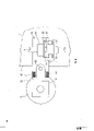
Fig. 1 is the diagrammatic side view that has the calender of apparatus of the present invention, and wherein roller system is closed up;
Fig. 2 represents as shown in Figure 1 a calender, and wherein roller system is left;
Fig. 3 is the view that the details of Fig. 1 is amplified;
Some embodiment of solution shown in Figure 3 are replaced in Fig. 4 to 6 expression.
Fig. 1 and 2 has schematically illustrated a supercalender, and its frame is designated by numeral 1, and roller system is designated by numeral 2.For clarity, in Fig. 1 and 2, some servicing units that are included in the calender have been saved, as output roller and equivalent thereof.As illustrated in fig. 1 and 2, the roller system 2 of supercalender comprises cylinder 3 on, one bottom roll 4 and several be arranged between cylinder and the bottom roll, a transition cylinder 5 that is positioned at another top, set described all cylinders are in stinging during clamping connection touches of nip each other.With usually the same, have one on the last cylinder 3 and place each end of cylinder and be connected in casing top half 32 on the calender frame 1, the piston 33 of described casing top half 32 acts on the bearing housing 31 of cylinder, with to roller system 2 loadings and reach the desirable value of linear load.The same with usual way, bottom roll 4 also has a following cylinder 45 that places each end of cylinder 4, and the described piston 46 of cylinder 45 down acts on the bearing housing 44 of bottom roll.Utilize all cylinders 45 down, roller system 2 can be opened with usual way.At the bottom roll shown in Fig. 1 and 24 are variable crown face pulleys, and it comprises swing roller cover 41, and bottom roll 4 utilizes hydraulic loaded part 43 to be supported in nip and stings in the folder plane on the non-rotary drum shaft 42.Bottom roll 4 is called as floating drum, and its drum sleeve 41 can be stung the folder in-plane along all nip and move with respect to drum shaft 42.In all transition cylinders 5 in roller system 2, have only a nethermost transition cylinder to have detailed numbering in Fig. 1 and 2, all transition cylinders two ends are rotatably mounted in all bearing housings 51.
The same with common mode, calender frame 1 has all guide rails 7, and also has all lifting axles 6 in every side of calender frame.Do not express the driven wheel that promotes axle 6 in each figure of accompanying drawing, this gear places the top of frame 1 in habitual mode, and utilizes it can make lifting axle 6 rotate and move in the vertical direction.Like this, when driven wheel rotated lifting axle 6, it faced upward or downward and moves a certain distance simultaneously.The bearing housing 31 of last cylinder 3 is connected in the support member 34 of cylinder, and this support member can vertically move along guide rail 7.Support member 34 has a stop part 35, promotes axle 6 and passes this stop part, and stop part 35 is along the longitudinal movement on axle 6.Promoting on the axle 6 and below stop part 35, wholeheartedly spindle nut 36 is housed.Under situation shown in Figure 1, when roller system 2 was closed up, this axle nut had a spacing b from stop part 35.
On the contrary, the bearing housing 51 rod parts 52 and the joint shaft 53 of transition cylinder 5 are connected on the support member 54 of transition cylinder rotationally.The support member 54 of described transition cylinder 5 also is placed on the calender frame 1, and can be for vertical movement along guide rail 7.The same with the mode of the support member 34 of last cylinder 3, support member 54 also has stop part 55, promotes axle 6 and passes this stop part.Below all stop parts 55 and from they a distance, there are all axle nuts 56 to be contained on the axle 6.Each axle nut 36,56 advantageously is equipped with an adjustable friction spare, utilizes it can provide suitable, enough frictional force between axle nut 35,56 and lifting axle 6.In addition, every axle nut 36,56 is equipped with a locking device (not shown), in case of necessity, relies on this device corresponding axle nut 36,56 can be locked on its position.When taking care the not locked device locking of spindle nut 36,56, when promoting axle 6 rotations, described axle nut rely on axle nut 36,56 friction member effect and with promoting axle 6 rotations.Otherwise when careful spindle nut was locked, when promoting axle 6 rotations, axle nut 36,56 still remained in its original position.Described locking device (not shown) for example can be a double acting pneumatic cylinders, can utilize this device to make 36,56 lockings of corresponding axle nut in case of necessity and does not rotate.Between the stop part 55 and axle nut 56 on the support member 54 that is arranged at transition cylinder 5, provide the weight reducing device 57 of pressure medium operation, its structure is shown in greater detail among Fig. 3 to 6 of accompanying drawing.
Weight reducing device comprises a body 57, and it is contained on the axle nut 56.Adorned a plate 58 on body 57, this plate contacts with the lower surface of stop part 55.Be provided with the power unit 59 of pressure medium operation on the body 57 of weight reducing device, the pressure medium is sent into described power unit 59, plate 58 promptly is lifted and leaves body 57.Power unit 59 comprises the cylinder thorax hole that is formed in the weight reducing device body 57, puts into piston in this cylinder thorax hole, and piston upwards withstands the lower surface of the plate 58 that places weight reducing device body 57 tops.
Situation shown in Figure 1 is that the roller system 2 of calender is in and closes up state, i.e. nip N
1... N
4Closure, corresponding, situation shown in the figure is nip N
1... N
4Opened, for the usefulness of for example changing cylinder, at this moment, the cylinder 3,4 in roller system, gapped a between 5.When roller system 2 is closed up, gapped b between the stop part 35 of last cylinder 3 and axle nut 36, when roller system 2 is opened, described gap just closed (as shown in Figure 2).When roller system is in closed position, power unit 59 work, promptly the hydraulic/pneumatic pressure medium is sent into power unit, and like this, the piston of power unit 59 upwards pushes away plate 58, heads on stop part 55.
Between the transition cylinder 5 that when roller system is shown in an open position, makes cylinder 3 and the top, and, between other transition cylinder, all can obtain same big gap a, select the stroke of piston in the power unit 59 long as shown in Figure 1, make that stroke in the power unit 59 of the top transition cylinder 5 is long to be (b+a), in the transition cylinder 5 of back, its stroke is always than the big a of the transition cylinder 5 of its front.This produces according to following situation, promptly roller system 2 instantaneous to open be by described power unit 59 pressure to be given off power unit, and the support member 47 of bottom roll glides along guide rail 7 and carries out by reducing bottom rolls 4 by means of cylinder 45 down.Because the bearing housing 51 of transition cylinder 5 is to utilize rod member 52 to link to each other with support member 54 with the pivot 53 that has articulation, described attenuating device 10 is arranged between described rod member 52 and the support member 54, and described attenuating device 10 is in operation and is supporting rod member 52 with respect to support member 54.Fig. 1 to 3 has represented first embodiment of described attenuating device, its operation and below will be described in detail meaning of the present invention.
But be noted that in this respect: when roller system 2 was opened, pressure was discharged and is the attenuating device 10 of cylinder-piston apparatus type.Thus, when roller system 2 was opened, the support member 54 of transition cylinder 5 leaned against on the axle nut fully, and rod member 52 rotates around joint shaft 53, and the base of rod member 52 and support member 54 are contacted, and therefore, support member 54 plays the stop effect that rod member 52 rotates.In all accompanying drawings, the gap between the base of rod member 52 and the support member 54 is exaggerated.Roller system 2 at first makes roller system 2 enter closed position by cylinder 45 down when open position closes up, then, and attenuating device 10 and power unit supercharging.
In order to regulate roller system 2, axle nut 56 is unclamped, can rotate so that promote axle 6.In the calender as Fig. 1 and 2, it is achieved in that pressure is discharged from casing top half 32 and power unit 59, so the bearing housing 44 of following cylinder and whole cylinder 4 are by cylinder 45 rises down.Also may promptly rely on the loaded member 43 of bottom roll 4 that cylinder overcoat 41 is risen with respect to axle 42 with such way.Be the attenuating device of cylinder-piston-type in the embodiment shown in fig. 1, unaffected in this case, but remain under the pressure.Thus, all transition cylinder 5 is each to rise one, at first, all rod members 52 is upwards rotated around all joint shafts 53, contact all support members 54 until the top edge of all rod members 52, thereby all support members 54 rises with all cylinders 5.All weight reducing devices 57 are provided with the member that falls that prevents the body member 57 of all weight reducing devices when all power unit 59 no pressure.So, described all body members 57 rise with all support members 54 and leave the top of all axle nuts 56, thereby enable to regulate lifting axle 6.
After finishing adjusting, when whole roller system 2 was close together, with regard to input pressure, the overcoat 41 of bottom roll just descended some highly in all power units 59.All thus power units 59 remain in all support members 54 on their position, and all rod members 52 rotate around all joint shafts 53, like this, form the gap between the bottom and upper segment of all rod members 52 and all support members 54.In such cases, the center of all transition cylinders 5 is positioned on the height of all joint shafts 53 in horizontal plane substantially.
Because all along with all transition cylinders 5 move together, all rod members 52 are very little with respect to the variation of the angle of all support members 54 to all support members 54 when roller system 2 rises and opens.In addition, to all transition cylinders 5, the variation of described angle equates that basically like this, all transition cylinders 5 still remain on the straight line each other.In supercalender, use abundant steam usually, steam is the recess of sending into nip or being formed by paper web, cylinder and output roller through all steam humidifying pipelines.But the shortcoming of logical steam is to impel gathering of dust in calender structure such as the guide rail 7.This causes such as support member 54 jams on guide rail 7.According to the present invention, because support member 54 moves with cylinder 5 all the time when roller system 2 is opened and regulated, so this jam phenomenon can not take place.
As top said, all attenuating devices 10 work between all support members of all rod members 52 and all transition cylinders 5, described all attenuating devices 10 are with respect to support member 54 spring bearing casees 51.In the embodiment shown in Fig. 1 to 3, described attenuating device comprises that one is preferably hydraulic pressure or pneumatic cylinder-piston apparatus, rely on the effect of pressure medium, this device produces the power that bearing housing 51 is rotated with respect to joint shaft 53, utilize this power, just can alleviate the caused load of output roller that may be connected with bearing housing, under reverse situation by bearing housing 51 and, this power just might make the shape generation deviation of cylinder 5, because big at the duty ratio mid portion of the lateral section of cylinder 5.Be added on journal load on the cylinder by what support member 54 caused, further alleviate again, utilize this power unit to make support member 54 raised with respect to axle nut 56 by power unit 59.Except removing journal load, attenuating device 10 has been decayed with equilibrium effectively by nip N
1N
4Kinetic power and swing.
Fig. 4 represents that one replaces the embodiment of solution shown in Figure 3.In solution shown in Figure 4, between the support member 54 of rod member 52 and transition cylinder 5, be positioned at the relative both sides of joint shaft 53, settled a pair of attenuating device 20, so, described device 20 acts on bearing housing 51, so that bearing housing rotates relative to direction along two with respect to joint shaft 53, solution shown in Figure 4 is very favorable, places the decay member of joint shaft 53 belows can alleviate journal load because utilize, and this situation is similar with the relevant description to Fig. 3.In solution shown in Figure 4, the decay member 20 that places joint shaft 53 tops is as a very effective pendulum damping tank, and it can the balanced power that is formed by nip, and decay is swung.
In the embodiment shown in fig. 5, the decay member 60 that is installed between rod member 52 and the support member 54 has replaced the cylinder-piston apparatus 10,20 shown in Fig. 3 and 4, and the most handy elastomeric material of this member is made.So, compare with the embodiment shown in 4 with Fig. 3, solution shown in Figure 5 is simpler, and manufacturing cost is also lower.In the embodiment shown in fig. 5, at their material and aspect of performance, make when utilizing power unit 59 that support member 54 is positioned over correct height with respect to axle nut 56 when making attenuating device 60, when the decay member 60 among compression Fig. 5, it can produce an enough big power, and this power of leaning on can be removed the journal load on the cylinder 5.In the solution in described accompanying drawing, on the member 60 of decaying can be made pendulum damping tank by special use.
Also can do some change, save decay member 60 fully the embodiment of Fig. 5.Especially no big external force on the bearing housing 51, only during idler pulley 5, this method is complete feasible.In addition, for example with Fig. 3, all embodiment in 4 and 5 combine also passable, making the attenuating device that is positioned at joint shaft 53 belows for example is cylinder-piston apparatus shown in Figure 3, last attenuating device then is a decay member 60 shown in Figure 5, and in this case, described member is used for decaying and swings.
Fig. 6 represents another embodiment, and the difference of it and above-mentioned those embodiment is that attenuating device 70 1 ends among this embodiment are supported on the rod member 52, is supported in the front of guide rail 7 at the other end relatively.About its operation and structure, attenuating device 70 can for example be a kind of cylinder-piston apparatus that is equivalent to attenuating device shown in Figure 3 10.In the embodiment shown in fig. 6, can be above joint shaft 53, between rod member 53 and support member 54, install one with similar decay member shown in Figure 5.
In sum, can summarize following content.Utilization is loaded on the support member 54 of transition cylinder 5 and the weight reducing device 57 between the axle nut 56, can remove the journal load that puts on the transition cylinder effectively, in addition, utilizes described weight reducing device 57, when roller system 2 can realize instantaneous beating as stated above.Utilization is loaded on the attenuating device 10,20,60 between support member 54 and the rod member 52, in according to solution of the present invention, can remove all bearing housing 51 and be supported in additional load on these bearing housings such as load that output roller brings.Certainly, described releasing also can design like this, is about to attenuating device 70 and places between rod member 52 and the calender frame 1.
In the operation, promptly when roller system 2 is in closed position, rely on weight reducing device 57, the support member 54 of transition cylinder 5 remains on their position with respect to the axle nut.Otherwise during rise and decline roller system 2, support member 54 moves with cylinder 5.According to solution of the present invention, can utilize the bottom roll 4 of a float type to rise roller system 2, reaching the purpose of regulating roller system, and utilize weight reducing device 57 can instantaneously open roller system 2(as mentioned above).
Above, the present invention that respectively desired to make money or profit with case description in conjunction with the accompanying drawings.But this does not also mean that the present invention is limited to all examples shown in the figure, but conceives in the scope in the present invention by subsidiary all patent claim limits, concerning being familiar with those skilled in the art, can make all changes.
Claims (9)
1, a kind of calender (calender, especially a kind of supercalender down together), one cover cylinder 2 is installed on its frame 1, this cover drum-shape is positioned on another as folded one on a cylinder and comprises cylinder 3 on, one bottom roll 4 and several placing, transition cylinder 5 between the bottom roll, described all cylinders 3,4,5 by all support members 34,47,54 are supported on the frame 1, all support members can be done moving of vertical direction along all guide rails 7 that are loaded on the frame, utilization is loaded on all lifting axles 6 and all axle nuts 56 that place on the axle on the frame 1, in described all support members, all support members 54 of all at least transition cylinders can running fix on vertical direction, it is characterized in that, all support members 54 of described all transition cylinders are supported on all lifting axles 6, can utilize and place the weight reducing device 57 of all pressure medium operations between all support members 54 and all axle nuts 56 for vertical movement, to reduce the journal load on the cylinder 5, and, all bearing housings 51 of all filter drum are connected in all support members 54, can with respect to one with cylinder 3, the parallel joint shaft 53 of 4,5 axis rotates, and utilizes all devices 10 that declines, 20,60,70 are supported on all support members 54 and/or the calender frame 1, so that balanced by the nip N between all cylinders
1, N
2, N
3, N
4Sting all power that folder motion causes and the swing of all cylinders 5 of decaying.
2, the friendship machine that presses and smooth as claimed in claim 1, it is characterized in that, all weight reducing devices 57 comprise the power unit 59 of all vertical effects, and specifically all cylinder-piston apparatus are supported in all support members 54 on the position that regulates at calender this device in service, and utilize its all transition cylinder 5 can be lowered by with the instantaneous roller system of opening, and, all attenuating devices 10,20,60,70 comprise the device of all power that the power that produces is caused by all bearing housings 51 of all transition cylinders 5 with compensation.
3, calender as claimed in claim 1 or 2 is characterized in that, in a roller system of closing up 2 and when rising roller system 2, all bearing housings 51 of all transition cylinders 5 are by 10,20,60,70 supports of all attenuating devices.
4, the described calender of arbitrary as previously mentioned claim, wherein the bottom roll 4 in the roller system 2 is variable crown face pulleys, the cylinder overcoat 41 of its rotation spreads all over its whole axial length, sting on the folder in-plane in nip, this overcoat can move with respect to drum shaft 42, described cylinder overcoat 41 is stung on the folder in-plane in nip and is utilized hydraulic loaded member 43 to be supported on the drum shaft 42, it is characterized in that, the overcoat 41 of bottom roll is moved in utilization with respect to axle 42, and the power unit 59 of weight reducing device is transformed into pressure-less state, roller system 2 is risen to reach regulate cylinder (3,4, the purpose of position 5) and the purpose that rotates and upgrades axle 6, thus, all support members 54 of all transition cylinders 5 move with all bearing housings 51 during rising.
5, the described calender of arbitrary as described above claim, it is characterized in that, all bearing housings 51 of all transition cylinders 5 are linked to each other with all support members 54, and, all attenuating devices 10,20,60 are installed between all rod members 52 and all support members 54, to limit of the rotation of all rod members 52 with respect to all support members 54, the rotation on the direction that moves that causes acting on by gravity on all transition cylinders 5 and all bearing housings 51 at least.
6, calender as claimed in claim 5, it is characterized in that, when roller system 2 was shown in an open position, all rod members 52 of all transition cylinders 5 were in respect to all support members 54 and rotate the position of a little corner around all joint shafts 53, and this corner is basic equating for all transition cylinders 5.
7, calender as claimed in claim 5, it is characterized in that, when roller system 2 raised to regulate when promoting axle 6, all rod members of all transition cylinders 5 are in respect to all support members 54 and upwards rotate the position of a little corner around all joint shafts 53, and this corner is basic equating for all transition cylinders 5.
8, the described calender of arbitrary as described above claim is characterized in that, all attenuating devices 10,20,70 comprise all cylinder-piston apparatus.
As arbitrary described calender in the claim 1 to 5, it is characterized in that 9, all attenuating devices 60 comprise all decay members of making of elastomeric material.
Applications Claiming Priority (2)
| Application Number | Priority Date | Filing Date | Title |
|---|---|---|---|
| FI890403 | 1989-01-27 | ||
| FI890403A FI83346C (en) | 1989-01-27 | 1989-01-27 | CALENDAR, SAERSKILT EN SUPERKALANDER. |
Publications (1)
| Publication Number | Publication Date |
|---|---|
| CN1044688A true CN1044688A (en) | 1990-08-15 |
Family
ID=8527793
Family Applications (1)
| Application Number | Title | Priority Date | Filing Date |
|---|---|---|---|
| CN90100455A Pending CN1044688A (en) | 1989-01-27 | 1990-01-24 | Calender, especially a kind of supercalender |
Country Status (10)
| Country | Link |
|---|---|
| US (1) | US5038678A (en) |
| JP (1) | JPH0314691A (en) |
| CN (1) | CN1044688A (en) |
| AT (1) | AT400858B (en) |
| CA (1) | CA2007975C (en) |
| FI (1) | FI83346C (en) |
| FR (1) | FR2642447B1 (en) |
| GB (1) | GB2227502B (en) |
| IT (1) | IT1239220B (en) |
| SE (1) | SE505494C2 (en) |
Cited By (2)
| Publication number | Priority date | Publication date | Assignee | Title |
|---|---|---|---|---|
| CN104047202A (en) * | 2013-03-12 | 2014-09-17 | 丹东天和实业有限公司 | Electric-pneumatic composite compaction roll mechanism |
| CN105544279A (en) * | 2016-02-04 | 2016-05-04 | 诸葛宝钧 | Super calender |
Families Citing this family (21)
| Publication number | Priority date | Publication date | Assignee | Title |
|---|---|---|---|---|
| DE4103620C1 (en) * | 1991-02-07 | 1992-02-27 | Sulzer-Escher Wyss Gmbh, 7980 Ravensburg, De | |
| JP2561663Y2 (en) * | 1991-06-19 | 1998-02-04 | 石川島播磨重工業株式会社 | Super calendar |
| DE4314670C2 (en) * | 1993-05-04 | 1996-02-01 | Kleinewefers Gmbh | calender |
| FI96334C (en) * | 1993-11-24 | 1996-06-10 | Valmet Paper Machinery Inc | Method for calendering paper or similar web material and calender applying the method |
| DE19520109C1 (en) * | 1995-06-01 | 1996-06-13 | Voith Sulzer Finishing Gmbh | Calender for total or part satinising avoiding uncontrolled friction |
| US5738007A (en) * | 1996-03-12 | 1998-04-14 | Beloit Technologies, Inc. | High nip load calender |
| FI107626B (en) * | 1996-05-06 | 2001-09-14 | Metso Paper Inc | Method of rapidly opening the roll system in a calender, especially super calender and a hydraulic system for the rolling system of a calender, especially super calender |
| DE19729531C2 (en) | 1997-07-10 | 2002-12-12 | Voith Paper Patent Gmbh | Paper calender |
| US5961899A (en) * | 1997-07-15 | 1999-10-05 | Lord Corporation | Vibration control apparatus and method for calender rolls and the like |
| DE19820087B4 (en) * | 1998-05-06 | 2005-06-23 | Eduard Küsters Maschinenfabrik GmbH & Co. KG | Calender for the treatment of a web |
| DE19945780C1 (en) * | 1999-09-24 | 2001-01-18 | Voith Paper Patent Gmbh | Mounting support for the intermediate roller in a calender assembly for finishing paper/cardboard webs has an overload safety system triggered by a breach of a set force threshold value |
| DE10010772C1 (en) * | 2000-03-04 | 2001-05-10 | Voith Paper Patent Gmbh | Calender has cylinders to support the rollers which are identical but have pistons at different settings for the closed roller nips each with a controlled outflow path for rapid calender roller separation |
| US6612228B1 (en) * | 2000-07-14 | 2003-09-02 | Metso Paper, Inc. | Calender and method for rebuilding a calender |
| FI116855B (en) | 2002-06-06 | 2006-03-15 | Metso Paper Inc | Arrangements for reducing roll nip |
| FI116303B (en) * | 2003-01-02 | 2005-10-31 | Metso Paper Inc | Multiroll calender for producing paper and board machines comprises roll stacks, thermo roll(s), and upper thermo roll |
| US20060042768A1 (en) * | 2004-08-27 | 2006-03-02 | Brown James T | Coated paper product and the method for producing the same |
| GB201508394D0 (en) * | 2015-05-15 | 2015-07-01 | Vivid Laminating Technologies Ltd | Pneumatic positioning of laminator rollers |
| GB2544805A (en) * | 2015-11-30 | 2017-05-31 | Vivid Laminating Tech Ltd | Pneumatic positioning of laminator rollers |
| CN105544278B (en) * | 2016-02-04 | 2017-06-16 | 淄博泰鼎机械科技有限公司 | The slide and supercalender of a kind of supercalender |
| CN105525530B (en) * | 2016-02-04 | 2017-06-16 | 淄博泰鼎造纸机械有限公司 | A kind of balance system of supercalender |
| CN105568735B (en) * | 2016-02-04 | 2017-08-01 | 淄博泰鼎造纸机械有限公司 | A kind of press polish roller unit of supercalender |
Family Cites Families (7)
| Publication number | Priority date | Publication date | Assignee | Title |
|---|---|---|---|---|
| US3155029A (en) * | 1962-11-22 | 1964-11-03 | Dominion Eng Works Ltd | Calenders |
| US3554118A (en) * | 1968-02-12 | 1971-01-12 | Tampella Oy Ab | Relief and raising device arrangement in multinip calender |
| DE2423504A1 (en) * | 1974-05-15 | 1975-11-27 | Kleinewefers Ind Co Gmbh | CALENDERS, IN PARTICULAR FOR PROCESSING PAPER Web |
| US4510859A (en) * | 1984-01-23 | 1985-04-16 | Beloit Corporation | Supercalender NIP relieving arrangement |
| DE3622398C1 (en) * | 1986-02-18 | 1987-06-19 | Escher Wyss Ag | Sepg. calender rolls - involves lowering pressure in hydraulic carrier support installations with time delay w.r.t. pressure to prevent damage to roll surface |
| DE3702245C3 (en) * | 1987-01-27 | 1993-12-23 | Kleinewefers Gmbh | calender |
| DE3711334A1 (en) * | 1987-04-03 | 1988-10-13 | Escher Wyss Gmbh | DEVICE FOR GUIDING THE ROLLS OF AN ESSENTIAL VERTICAL CALANDER |
-
1989
- 1989-01-27 FI FI890403A patent/FI83346C/en not_active IP Right Cessation
- 1989-12-22 AT AT0293189A patent/AT400858B/en not_active IP Right Cessation
- 1989-12-27 US US07/457,278 patent/US5038678A/en not_active Expired - Fee Related
- 1989-12-28 GB GB8929242A patent/GB2227502B/en not_active Expired - Fee Related
-
1990
- 1990-01-17 CA CA002007975A patent/CA2007975C/en not_active Expired - Fee Related
- 1990-01-18 IT IT19093A patent/IT1239220B/en active IP Right Grant
- 1990-01-24 CN CN90100455A patent/CN1044688A/en active Pending
- 1990-01-26 FR FR9000932A patent/FR2642447B1/en not_active Expired - Fee Related
- 1990-01-26 SE SE9000278A patent/SE505494C2/en not_active IP Right Cessation
- 1990-01-29 JP JP2018804A patent/JPH0314691A/en active Pending
Cited By (2)
| Publication number | Priority date | Publication date | Assignee | Title |
|---|---|---|---|---|
| CN104047202A (en) * | 2013-03-12 | 2014-09-17 | 丹东天和实业有限公司 | Electric-pneumatic composite compaction roll mechanism |
| CN105544279A (en) * | 2016-02-04 | 2016-05-04 | 诸葛宝钧 | Super calender |
Also Published As
| Publication number | Publication date |
|---|---|
| CA2007975C (en) | 1995-05-23 |
| ATA293189A (en) | 1995-08-15 |
| IT9019093A1 (en) | 1990-07-28 |
| SE9000278L (en) | 1990-07-28 |
| CA2007975A1 (en) | 1990-07-27 |
| FI83346C (en) | 1991-06-25 |
| AT400858B (en) | 1996-04-25 |
| IT1239220B (en) | 1993-09-28 |
| FR2642447B1 (en) | 1996-05-31 |
| SE9000278D0 (en) | 1990-01-26 |
| GB2227502B (en) | 1992-10-21 |
| FI83346B (en) | 1991-03-15 |
| GB8929242D0 (en) | 1990-02-28 |
| JPH0314691A (en) | 1991-01-23 |
| US5038678A (en) | 1991-08-13 |
| FR2642447A1 (en) | 1990-08-03 |
| GB2227502A (en) | 1990-08-01 |
| SE505494C2 (en) | 1997-09-08 |
| IT9019093A0 (en) | 1990-01-18 |
| FI890403A0 (en) | 1989-01-27 |
| FI890403A (en) | 1990-07-28 |
Similar Documents
| Publication | Publication Date | Title |
|---|---|---|
| CN1044688A (en) | Calender, especially a kind of supercalender | |
| DE69413202T3 (en) | METHOD FOR CALANIZING A PAPER OR SIMILAR MATERIAL RAIL AND CALENDAR FOR CARRYING OUT THE METHOD | |
| US3270664A (en) | Calender stack | |
| EP0280038B1 (en) | Calender | |
| US5058472A (en) | Rotary cutting apparatus | |
| CA1231573A (en) | Supercalender nip relieving arrangement | |
| EP0260525A2 (en) | Machine for making single-faced corrugated board | |
| DE4035986A1 (en) | CALENDAR FOR ON-LINE CONNECTION TO A PAPER MACHINE | |
| US4501197A (en) | Supercalender edge nip relieving | |
| CN1051219A (en) | The actuating unit structure that is used for the machine calender roller | |
| CN1896377A (en) | Calender | |
| FI81633C (en) | ADJUSTMENT OF SUPPLY AND SUPER CALENDAR. | |
| US3611917A (en) | Calender stack with swimming roll | |
| CN212150950U (en) | Paper products coiling mechanism | |
| CN2592373Y (en) | Heating plate mechanism for bonding and drying machine | |
| CN2556015Y (en) | Automatic tension balancing tackle | |
| CN214568306U (en) | Adjustable V-shaped carrier roller set | |
| EP0943423B1 (en) | Heating device for a corrugating system | |
| EP0931877B1 (en) | Calender for a web material, in particular a paper web | |
| JP2888617B2 (en) | Rotary cutting device | |
| CN2053223U (en) | Double-roller calender with adjustable eccentricity | |
| DE4026774A1 (en) | Paper polishing roller assembly giving high speed working - has hard top and bottom rollers with a soft cladding at the centre rollers for high-speed working | |
| CN85103249A (en) | Supercalender edge chuck discharges | |
| CN116122072A (en) | Bottom roller removing device of calender | |
| DE10297367B4 (en) | Method and device for exchanging an intermediate roller of a roller device |
Legal Events
| Date | Code | Title | Description |
|---|---|---|---|
| C06 | Publication | ||
| PB01 | Publication | ||
| C01 | Deemed withdrawal of patent application (patent law 1993) | ||
| WD01 | Invention patent application deemed withdrawn after publication |