CN1042760C - Method and apparatus for controlling direction of excavating machine - Google Patents
Method and apparatus for controlling direction of excavating machine Download PDFInfo
- Publication number
- CN1042760C CN1042760C CN92105799A CN92105799A CN1042760C CN 1042760 C CN1042760 C CN 1042760C CN 92105799 A CN92105799 A CN 92105799A CN 92105799 A CN92105799 A CN 92105799A CN 1042760 C CN1042760 C CN 1042760C
- Authority
- CN
- China
- Prior art keywords
- excavator
- target
- head
- reference line
- light
- Prior art date
- Legal status (The legal status is an assumption and is not a legal conclusion. Google has not performed a legal analysis and makes no representation as to the accuracy of the status listed.)
- Expired - Fee Related
Links
Images


Classifications
-
- E—FIXED CONSTRUCTIONS
- E21—EARTH DRILLING; MINING
- E21D—SHAFTS; TUNNELS; GALLERIES; LARGE UNDERGROUND CHAMBERS
- E21D9/00—Tunnels or galleries, with or without linings; Methods or apparatus for making thereof; Layout of tunnels or galleries
- E21D9/003—Arrangement of measuring or indicating devices for use during driving of tunnels, e.g. for guiding machines
- E21D9/004—Arrangement of measuring or indicating devices for use during driving of tunnels, e.g. for guiding machines using light beams for direction or position control
-
- G—PHYSICS
- G01—MEASURING; TESTING
- G01C—MEASURING DISTANCES, LEVELS OR BEARINGS; SURVEYING; NAVIGATION; GYROSCOPIC INSTRUMENTS; PHOTOGRAMMETRY OR VIDEOGRAMMETRY
- G01C7/00—Tracing profiles
- G01C7/06—Tracing profiles of cavities, e.g. tunnels
Landscapes
- Engineering & Computer Science (AREA)
- Mining & Mineral Resources (AREA)
- Environmental & Geological Engineering (AREA)
- General Physics & Mathematics (AREA)
- Radar, Positioning & Navigation (AREA)
- Remote Sensing (AREA)
- Physics & Mathematics (AREA)
- Multimedia (AREA)
- Life Sciences & Earth Sciences (AREA)
- General Life Sciences & Earth Sciences (AREA)
- Geochemistry & Mineralogy (AREA)
- Geology (AREA)
- Excavating Of Shafts Or Tunnels (AREA)
Abstract
There is disclosed a method and an apparatus for easily controlling the advancing direction of an excavating machine without causing the excavating machine to largely trace in a zigzag way. The direction control is done by the steps of mounting a reflector on a head portion of a shield body so as to receive a light beam directed along an imaginary reference line, mounting a target on a tail portion of the shield body so as to receive the reflected light beam from the reflector, controlling means for correcting the direction so that the reflected light beam may be irradiated at an objective position within the target, and thereby controlling the advancing direction of the excavating machine so that a subjective portion at the top end of the head portion may follow along the reference line.
Description
The present invention relates to the control method and the control device of the direction of advance of excavator, the closed fuselage of this excavator employing is provided with head and can be its crooked afterbody that connects after this head, specifically, in the method and apparatus of the control excavator direction of advance that the present invention relates to, utilized along the plan line in the tunnel of waiting to build and the light of reference line direction indication.
In the prior art, be provided with the sealed tunnel excavator of the closed fuselage of can be relatively crooked head that connects and afterbody by employing, when offering pipeline one class tunnel, shift one's position when the plan circuit that excavator needs basis to plan to build the tunnel of making, then the direction of advance of variable excavator is done so-called adjustment in direction.
As one of in the method and apparatus of above-mentioned this direction control, be that displacement with laser one lightlike line that determine to point to the plan circuit of planning to build the tunnel of making is a benchmark, the target that receives this light promptly is installed on aforementioned afterbody, make light shine the target location of target, in other words, make light become the target location, revise the direction of advance of excavator in view of the above towards the irradiation position of this target, specifically, promptly revise the direction of head with respect to afterbody.
In this in the above known direction-controlling method and the device, target is configured to, when the axis of excavator consistent with the plan line, excavator with respect to the position of plan line and posture all correctly the time, light promptly shines to the target location.Like this, in case the line of excavator diasporometer, the light irradiation position of directive target is promptly fallen outside the target location.In this known direction-controlling method and device, be to make light according to direction of advance from excavator to the target location that revise.
But, adopt in the direction-controlling method and device of light and target at this kind, owing to be that the light of directing line is shone directly on the target that is located at afterbody, so only be along the correction of reference line travel direction the position of target configuration place in the reference direction.In such direction control, even the target location of light directive target, head can tilt with respect to afterbody or reference line under many circumstances, thereby makes adjustment in direction operation complexity.
In addition, in this direction of advance control method and device, owing to be to cross position that the reference line displacement makes target configuration place in reference line direction reference line unanimity therewith by the front end that makes head, thereby head is very big with respect to the displacement of reference line.Like this, herein in direction-controlling method and the device, during excavator advances in certain distance, the wriggling number of times of head is not only many but also scope wriggling is also big, the result makes excavator simultaneously carry out a large amount of wrigglings, and one side is advanced, and makes the adjustment in direction operation complicated more.
As another kind of direction-control apparatus, be that index plate and pointer are located at head and afterbody respectively,, determine the bending direction and size of head with respect to afterbody according to the pointer position on the index plate, revise the direction of advance of excavator in view of the above, particularly revise the direction of head with respect to afterbody.
But in the known direction-controlling method of this employing index plate and pointer and device, though can determine the direction and size of head with respect to the afterbody bending, whether but it is consistent with reference line to distinguish excavator, even if can revise head, but can not revise the head that makes when excavator is consistent with reference line with respect to the bending direction of afterbody and big or small with respect to the bending direction of afterbody and size.
Head is with respect to the direction and size of afterbody bending in the time of making excavator consistent with reference line in order to revise, can consider to fully utilize above two kinds of known direction control technologys, but because the offset direction of the light irradiation position of directive target is irrelevant with size with respect to the offset direction of calibration with size and pointer, operating personnel have to come the travel direction correction according to the information that is independent of each other, and need be very familiar to the adjustment in direction operation.
The present invention's purpose promptly is, needn't make excavator make a large amount of wrigglings, just can control the direction of advance of excavator simply.
Excavator direction of advance control method of the present invention, be to make light point to excavator along the reference line of supposing from the rear of excavator, receive this light by the speculum that is installed on the closed fuselage head, receive this reflection ray by the target of being located on this afterbody again, make this reflection ray shine target location in the target come controlling party to correction.
Excavator direction of advance control device of the present invention then comprises: the speculum and the target that is installed in the closed fuselage afterbody that are installed in the closed fuselage head, the former is used for receiving the light of the reference line directive excavator from the excavator rear along hypothesis, and the latter then is used for receiving the reflection ray from above-mentioned speculum.
Target location in the target for example can be the slave of certain position of head front end as direction control object, and this slave can become the irradiation position of the reflection ray of directive target when coming down on reference line.
From be arranged in the initial vertical shaft light source sent as the lightlike line of the laser of benchmark, the mirror reflects backstage on head, the target on the directive afterbody.
Reflection ray is with respect to the addendum modification and the displacement direction of the irradiation position of target location in the target, excuse portion with respect to the angle of afterbody, afterbody with respect to the angle of light, head with respect to the angle of light and the addendum modification of reference line and light etc. and different.But reflection ray is with respect to the displacement direction of the irradiation position of target location, and is main relevant with respect to the incline direction of reference line with head.
Like this, in order to make reflection ray directive target location, when the direction of revising head with respect to afterbody is advanced excavator, even excavator with respect to the position of reference line and posture none when correct, usually it is consistent with the direction of reference line also excavator to be adapted to the subordinate portion that makes the head front end, and its excavator advances under the condition of reference line at its head front end.As a result, excavator just can advance in respect to its tram of reference line correction and correct body position.
According to the present invention, be after the light as benchmark is passed through the mirror reflects of head, shine the target of afterbody, become the method that target location in the target is used as controlling adjustment in direction by the position that reflection ray shone that makes the directive target, reach the purpose of control excavator direction of advance thus, thereby make direction control become easy.
In addition, do direction control owing to can make the leading section of excavator along reference line, compare with the technology that direction is revised along reference line in the known position that makes target placement in the reference line direction, the wriggling number of times of head is few and the wriggling scope is also little, so just can reduce the wriggling number of times of excavator and dwindle its wriggling scope.
Target location in the target when aforementioned subordinate portion come down on reference line for the irradiation position of above-mentioned reflection ray the time, any part of getting calmly it all is fine.Any part when in other words, subordinate portion can get and shine the target location as above-mentioned reflection ray on reference line.
But, the position of reflection ray directive target when the target location in the target is preferably got excavator and is in tram and correct body position with respect to reference line.Like this, because subordinate portion is excavator position on reference line when being in tram and correct body position with respect to reference line, the wriggling number of times of head can be still less, and the scope of wriggling also can be littler.In view of the above, the wriggling number of times of excavator also still less and the wriggling scope is also littler.The result makes that excavator is directly to march forward basically.
Deflector preferably is set, and the light that can make directing line from the light path and the directional mirror of this reference line displacement, like this, even utilize the light that points on the afterbody axis, also can make this light walk around obstruction in the closed fuselage along.
But better method is to adopt such deflector, makes the radially foreign side deflection along the light of reference line towards the sealing fuselage, and the light that makes deflection is towards speculum, and allows the radially central authorities of this sealing fuselage of reflection ray directive of speculum.Like this, can make above-mentioned light not be subjected to the influence of obstruction in the closed fuselage, shortening from the head, front end can improve the precision of direction control thus to the distance of speculum.
Above-mentioned target preferably is equipped with the translucent transmittance section that the light that allows toward mirror passes through and is received from the light accepting part that mirror reflects is returned.Like this, according to the irradiation position of light directive transmittance section and the reflection ray irradiation position to the light accepting part, just can learn that excavator is with respect to the particularly afterbody of the light addendum modification with respect to light.
Also can near target, dispose television camera, monitor its image by watch-dog.
The position at aforementioned target place is preferably set for, when excavator is in tram and correct body position with respect to reference line, makes this target location be in distance from the speculum to the target location and be equivalent to from reference line and excavator front end intersection point to aforementioned 1/2 the position of making the crooked flexural center distance that is connected.Like this, do not make the subordinate portion transcendence basis directrix displacement that is set on the excavator front end, just can easily control the direction of advance of excavator, thereby compare with control device, just can reduce the wriggling number of times of excavator significantly and dwindle its wriggling scope greatly with known direction-controlling method.
As for the distance from the speculum to the target location, when being in tram and correct body position as excavator with respect to reference line, by excavator front end partly being advisable to the distance of above-mentioned flexural center to get.So just can further dwindle the wriggling scope of excavator.
Brief description accompanying drawing of the present invention.
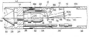
Fig. 1 is the figure of irradiation position of sectional drawing and the light that shows bright directive target of embodiment of excavator that shows the bright the present invention's of being equipped with direction-control apparatus.
Fig. 2 is the schematic diagram of principle that is used for illustrating the present invention's adjustment in direction method.
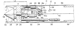
Fig. 3 is the sectional drawing that shows the excavator embodiment of the another kind of direction-control apparatus of the bright the present invention of being equipped with.
Fig. 4 is the sectional drawing that shows the excavator embodiment of another direction-control apparatus of the bright the present invention of being equipped with.
Referring now to accompanying drawing, embodiments of the invention is described.
In Fig. 1, enclosed tunnel excavator 10 includes the closed fuselage 12 of tubular, and the latter has head 14 and the afterbody 16 that links to each other with its rear portion.Head 14 can be the flexural center point 20 on the axis 18 of excavator 10 (being actually its afterbody 16) as the center with afterbody 16, do the combination of bendable musical form, and a collection of jack of being used by the adjustment in direction of revising orientation of head with respect to afterbody 22 makes it to interconnect.
The front end of afterbody 16 is admitted in the rear end of head 14 in flexible mode.Afterbody 16 is divided into by a collection of bolt as separating but can not do relative displacement and a plurality of cylindrical body 16a, the 16b that have linked.Equally, head 14 also may be partitioned into and does separable by a collection of bolt but can not do relative displacement and a plurality of cylindrical body of connecting.
Be divided into the place ahead district and rear district by next door 24 within the head 14.In the next door 24, bent axle 26 is supported to can rotation around axis 18.Bent axle 26 is assembled into and makes its eccentric part become above-mentioned the place ahead district.In the eccentric part of bent axle 26, support a tumbler 28 in rotating mode, in tumbler 28, then be equipped with and dig shovel assembly 30.This digs the shovel assembly is to be provided with from the radially overhanging a collection of arm of tumbler 28 and a collection of teeth that is located at these arm front ends equipment to be arranged earlier.
Also be equipped with in the next door 24 and be used for the rotating mechanism 32 of turning crankshaft 26.Tumbler 28 is configured to digging shovel assembly 30, and rotation that can be by bent axle 26 is the rotation (rotation) at center for the rotation of central axis (revolution) and work with the eccentric part of bent axle 26 as axis 18.The structure of this respect for example can be speciallyyed permit disclosed technology in (disclosing) clear 63-189596 communique referring to Japan, owing to control no direct relation with direction, economizes the detailed description that removes it.
By water service pipe 34 can with excavate muddy water that thing discharges usefulness from ground supply in head the place ahead district of 14.The muddy water that supplies to this place ahead district is then arranged on the ground through discharge pipe 36 jointly with the excavation thing.36 of water service pipe 34 and discharge pipes stretch to ground through afterbody 16, concrete pipe and so on tubing 38 and initial vertical shaft (not shown in the figures bright).
Laser one lightlike line that the light source of aforementioned initial shaft sends is located in the direction-control apparatus utilization.In illustrative example, be the reference line that is scribed ss in the tunnel waiting to build (among the figure show with pipeline bright), light 40 sensing plan lines are reference line.But the imagination line that also can adopt and plan line parallel is a reference line, and also can allow light 40 sensing plan abreast line.
Direction-control apparatus comprises: stretch to arm 42 in the afterbody 16 from next door 24, be installed in this arm rear end carriage 44, be installed on carriage 44 be used for accepting light speculum 46, be used for accepting reflection ray 48 and its television camera 52 that is loaded on the target 50 on the afterbody 16 and this target is made a video recording with target location from this speculum.
Target 50 is set on the carriage 54 that is loaded in the afterbody 16.Be provided with translucent the 50a that the light 40 that allows toward mirror 46 passes through in the target 50 and accept light accepting part 50b from the reflection ray 48 of speculum 46.Therefore, shown in Fig. 1 (B), be formed with the hot spot 40a that the light 40 by translucent 50a of directive shines among the target 50, and the hot spot 48a that shines by the reflection ray 48 of directive light accepting part 50b.
When excavator 10 is in tram and correct body position with respect to reference line, light 40 promptly points to axis 18, the regulation position of transmittance section 50a by target 50 arrives speculum 46, and reflection ray 48 promptly shines the regulation position on the light accepting part 50b of target 50.The irradiation position of the reflection ray of directive target 50 is the target locations (referring to Fig. 2) that are used for direction control at this moment, and the cross part of the front end of excavator 10 and reference line just becomes the subordinate portion 58 of direction control object.
In illustrated example, subordinate portion 58 is the cross part of end and reference line before the head 14.Thereby when light 40 directing lines and the axis 18 of excavator 10 when consistent with reference line, subordinate portion 58 promptly becomes the center of head 14 front ends.But subordinate portion 58 also can be other position.
During excavation, when tumbler 28 with dig of the effect of shovel assembly 30 when being in rotary state by rotating mechanism 32, excavator 10 promptly advances under the total pushing mechanism effect in being arranged at aforementioned initial vertical shaft.At this moment, reflection ray 48 is promptly according to position and the posture of excavator 10 with respect to reference line, according to the assigned position to light accepting part 50b.Like this, operating personnel just control jack 22 so that light 48 shines to the target location.Can control excavator 10 in view of the above, make it to advance by tram and correct body position with respect to reference line.
Secondly referring to Fig. 2, the control method of utilizing this kind direction-control apparatus to control the direction of advance of excavator 10 is described.
As shown in Figure 2, subordinate portion 58 is cross parts of end and reference line 70 before the head 14, light 40 directing lines 70, and the target location of light accepting part 56b is on the axis 18.Fig. 2 (A), (B) with (C) in, axis 18 is parallel with reference line 70; In Fig. 2 (D), axis 18 tilts with respect to reference line 70.In addition, Fig. 2 (A), (B) with (C) in, in the direction of the line 76 of the illumination part position of vertical reflector 44 (in example shown in Figure 2, be the closure of subordinate portion 58 and flexural center point 20) in, speculum 46 is compared with the distance L 2 of subordinate portion 58 and flexural center point 20 with the distance L 1 of target location 72, be respectively the latter's 1/2nd, greater than it 1/2nd and less than its 1/2nd.And in figure (2) D, 1 of distance L is got as 1/2nd of distance L 2.
Shown in Fig. 2 (A), distance L 1 is 1/2nd of a distance L 2, and when the irradiation position 74 of the reflection ray 48 of directive target and target location 72 were consistent, even head tilts with respect to afterbody, subordinate portion 58 was also on reference line 70.In this state, with respect to the direction of afterbody excavator is advanced if do not revise head, then this excavator displacement that can blow slowly towards the direction of its axis 18 convergence reference lines 70, subordinate portion 58 then can be from reference line 70 slowly displacement downwards, simultaneously, 74 72 displacements slowly downwards of irradiation position from the target location.
For this reason, in situation shown in Fig. 2 (A), otherwise make irradiation position 74 72 displacements and make irradiation position 74 upward from the target location near target location 72, just should make head with respect to afterbody with the more existing situation angular turn of direction (being clockwise direction in the drawings) more up, revise the direction of head with respect to afterbody, in this while, and after revising, excavator is advanced.Like this, it is consistent with reference line 70 that excavator just can be modified to axis 18 slowly, and subordinate portion 58 is consistent with reference line 70, tram and correct body position that the relative afterbody of head does not tilt.
Shown in Fig. 2 (B), the distance L 1 of this moment is greater than 1/2nd of distance L 2, and consistent with target location 72 when the irradiation position 74 of the reflection ray 48 of directive target, even head tilts with respect to afterbody, subordinate portion 58 is but on reference line 70.In this state, with respect to the direction of afterbody excavator is advanced as not revising head, then excavator will change slowly towards the direction of its axis 18 convergence reference lines 70, though subordinate portion 58 convergence reference line lentamente, 74 72 displacements gradually upward of irradiation position from the target location.
Therefore, in situation shown in Fig. 2 (B), otherwise make irradiation position 74 72 make irradiation position 74 near target location 72 towards the top displacement from the target location, also should make head with respect to the angular turn of afterbody with existing situation direction (being clockwise direction in the drawings) more up, revise the direction of head with respect to afterbody, in this while, and excavator is moved on.Like this, it is consistent with reference line 70 that excavator just can be adjusted to axis 18 gradual change type, and subordinate portion 18 is consistent with reference line 70, tram and correct body position that the relative afterbody of head does not tilt.
Shown in Fig. 2 (C), distance L 1 is less than 1/2nd of distance L 2, even the irradiation position 74 of the reflection ray 48 of directive target is consistent with target location 72 at this moment, because head tilts with respect to afterbody, subordinate portion 58 is in the below of reference line 70.Under this state, as if not revising the direction of head excavator is advanced with respect to afterbody, the displacement though excavator can blow slowly towards the direction of its axis 18 convergence reference lines 70, subordinate portion 58 will be from reference line 70 slow displacement towards the below, then 72 displacements gradually upward from the target location of irradiation position 74.
Therefore, in situation shown in Fig. 2 (C), otherwise make irradiation position 74 72 make irradiation position 74 near target location 72 towards the top displacement from the target location, also should make head with respect to the angular turn of afterbody with more existing situation direction (being clockwise direction in the drawings) more up, revise the direction of head with respect to afterbody, in this while, and excavator is advanced.Like this, it is consistent with reference line 70 that excavator just can be modified to axis 18 gradually, and subordinate portion 58 is consistent with reference line 70, tram and correct body position that head does not tilt with respect to afterbody.
Shown in Fig. 2 (D), if head tilts with respect to afterbody, axis 18 tilts with respect to reference line 70 simultaneously, and then the irradiation position 74 of the reflection ray 48 of directive target is inconsistent with target location 72.At this moment, irradiation position is with respect to the displacement direction of target location, then look head with respect to the incline direction of afterbody and size and axis 18 with respect to the incline direction of reference line 70 with size different (above in illustrated example being).
Under state shown in Fig. 2 (D), with respect to the direction of afterbody excavator is advanced if do not revise head, then excavator is towards the displacement that blows slowly of its axis 18 and reference line 70 consistent directions, and irradiation position then approaches apparent target location 72.
But in working control work, head is not understood with respect to the direction and the size of the inclination of reference line 70 with respect to the incline direction of afterbody and inclination size and axis 18.
Therefore, in situation shown in Fig. 2 (D), for making irradiation position 74 convergence target locations 72, should make head with respect to the angular turn of afterbody with existing situation direction (being clockwise direction among the figure) more up, revise the direction of head with respect to afterbody, in this while, and excavator is advanced.Like this, it is consistent with reference line 70 that excavator just can be modified to axis 18 gradually, and subordinate portion 58 is consistent with reference line 70, tram and correct body position that head does not tilt with respect to afterbody.
As mentioned above, for example travel direction correction in the following manner in the present invention.
When irradiation position 74 displacements or when being indexed to 72 tops, target location, make irradiation position 74 convergence target locations 72, can make the angle rotation of the direction that the more existing situation of the relative afterbody of head more makes progress (being clockwise direction among the figure), revise the direction of head, simultaneously and after revising excavator is advanced in this with respect to afterbody.
When irradiation position 74 displacements or when being indexed to 72 belows, target location, for making irradiation position near the target location, can make the angle rotation of head with respect to the more existing situation of afterbody direction (being counter-clockwise direction among the figure) more down, revise the direction of head with respect to afterbody, in this while and after revising, make excavator advance.
When irradiation position 74 and target location 72 are consistent, for allow irradiation position 74 no longer displacement open target location 72, can make head with respect to the angle rotation of direction (clockwise direction among the figure) down of the more current position of afterbody, relative afterbody correction cephalad direction, in this simultaneously and correction 3 after, make excavator advance.
In above-mentioned any situation, all excavator can be modified to inchmeal and make its axis 18 consistent with reference line 70, subordinate portion 58 is consistent with reference line 70, tram and correct body position that head does not tilt with respect to afterbody.Revising operation can carry out with artificial or automaton.
No matter with respect to the size of distance L 2 how distance L 1, where head is inclined to respect to afterbody, axis 18 also has inclination and irradiation position 74 and target location 72 inconsistent with respect to reference line 70, all can adopt the adjustment in direction jack of the direction of revising the relative afterbody of head, the travel direction correction.
In state shown in Figure 2, distance L 1 is greater than distance L 2 two/for the moment, consistent with target location 72 when irradiation position 74, subordinate portion 58 can not run off reference line.In contrast, when distance L 1 less than 1/2nd of distance L 2, when the irradiation position 74 of the reflection ray 48 of directive target and target location 72 were consistent, subordinate portion 58 had just run off reference line 70.Like this,,,, the wriggling scope of head front end is dwindled, improve the rectilinear propagation of excavator so the situation of same L1<1/2 L2 is compared owing to can control subordinate portion 58 within reference line 70 when distance L 1 surpasses 1/2nd of distance L 2.But, even in the situation of L1<1/2 L2, to compare with the method and apparatus of known direction control, the wriggling number of times of excavator can reduce, and the wriggling scope also can be dwindled.
Again in state shown in Figure 2 when L1=1/2 L2, if irradiation position 74 is consistent with target location 72, then subordinate portion 58 is consistent with reference line 70.But when L1>1/2 L2, even irradiation position 74 is consistent with target location 72, subordinate portion 58 is not consistent with reference line 70 yet.Therefore, when L1=1/2 L2, compare, can dwindle the wriggling scope of head front end with L1>1/2/2 situation.
As mentioned above, if make head with respect to afterbody towards irradiation position 74 with respect to the displacement of target location 72 or the angle of direction of displacement, do further to rotate than its existing position, 72 displacements or just 72 displacements from the target location when irradiation position 74 from the target location, in order to make irradiation position 74 convergence target locations 72 or not 72 displacements from the target location, only need the correction head to get final product with respect to the direction of afterbody, thereby compare with known adjustment in direction technology, the adjustment in direction operation here is easy.
Utilize direction-controlling method of the present invention and device, when the axis of excavator is consistent with reference line, often can make head become to make subordinate portion 58 subtend reference lines 70 with respect to the adjustment in direction of afterbody, in contrast, in known direction control technology, when the axis that makes excavator is consistent with reference line, for head is departed from the direction of reference line towards the head front end with respect to the direction of afterbody, promptly feasible position corresponding to subordinate portion 58 runs off reference line, need do many correction work.Therefore, according to direction-controlling method of the present invention and device, compare with known direction control technology, the interior wriggling number of times of per unit distance will reduce, and the wriggling scope also will be dwindled.
If mirror arrangement is become, make the line 76 of light 40 in irradiation position of toward mirror 46 parallel with the imaginary line of flexural center point 20 with connection subordinate portion 58, in other words, when making the reflecting surface of this mirror and this imaginary line quadrature, when then subordinate portion 58 comes down to be on the reference line 70, done the target location 72 in the target getting, so just made the adjustment in direction operation become easy towards the irradiation position 74 of reflection ray.But speculum can as above not dispose yet.
In addition, can be not yet the light 40 of directing line 70 directly into toward mirror 46 so that mirror arrangement becomes to make its center consistent with axis 18, and can be configured to speculum 46 towards the form of the displacement radially outward of excavator 10.
The deflector 60 that in direction-control apparatus shown in Figure 3, also contains the light path of the light 40 that changes, 60 of deflectors are comprising the light 40 deflection afterbodys first deflection mirror 62 of foreign side radially that makes directing line, and the second deflection mirror 64 that this light of being partial to is got be parallel to reference line.
In the situation of device shown in Figure 3, if excavator 10 is advanced according to correct position and correct posture with respect to reference line, light 40 will point to axis 18, the regulation position of transmittance section 50a by target 50, arrive speculum 46, and reflection ray 48 just shines the position of the light accepting part 50b of target 50.In addition, even head 14 tilts with respect to afterbody 16, when subordinate portion 58 was on the reference line, reflection ray 48 just can shine on the target location of light accepting part 50b.
But because subordinate portion 58 is not on reference line the time, reverberation is through 48 positions that promptly shine the target location of departing from light accepting part 50b, can know that subordinate portion 58 has departed from reference line, at this moment operating personnel just can regulate jack makes reflection ray shine the target location of light accepting part 50b.So, just can control excavator 10 and make it to advance according to correct position and correct posture with respect to reference line.
When adopting device shown in Figure 3,, can effectively utilize the space in the afterbody 16 owing to point to the light 40 energy cut-through things of axis 18.Simultaneously, in device situation shown in Figure 3, when excavator disposes by tram and correct body position with respect to reference line, dispose target 50 in mode and be advisable according to distance L 1>1/2 L2.
In direction-control apparatus shown in Figure 4, contain other deflector 80 of the light path of the light 40 that changes.This deflector 80 comprises: just the light on the directing line 50 deflection afterbodys 16 radially foreign side the first deflection mirror 82, allow the semitransparent mirror 84 that this deflection light passes through and make the second deflection mirror 86 by the parallel sensing axis 18 of the light of this semitransparent mirror, they are installed on the afterbody 16 by carriage 88.
The second deflection mirror 86 is assembled into, and makes the light directional mirror by semitransparent mirror 84 and make from the reflection ray 48 of speculum 46 to point to semitransparent mirrors 84.This semitransparent mirror 84 allows to pass through and the directive second deflection mirror 86 through the light of the first deflection mirror, 82 deflections, can allow the reflection ray 48 of being partial to by the second deflection mirror 86 point to targets 50 simultaneously.52 of television cameras are assembled into and can take its overall condition from target 50 rears.
In device shown in Figure 4, when excavator 10 when advancing with respect to the tram of reference line and correct body position, light 40 points to axis 18, the certain position of transmittance section 50a by target 50 and deflector 80 arrive speculums 46, and reflection ray 48 then shines the target location of the light accepting part 50b of target 50 through deflector 80.Simultaneously, even head 14 tilts with respect to afterbody, when subordinate portion 58 was on the reference line, reflection ray 48 promptly shone the target location of light accepting part 50b.
But, in case subordinate portion 58 departs from reference line, shine the position of the target location of departing from light accepting part 50b according to reflection ray 48, can learn that subordinate portion 58 has departed from reference line, make reflection ray 48 shine the target location of light accepting part 50b so operating personnel just can regulate jack.Thus, can control excavator 10 advances according to tram and correct body position with respect to reference line.
According to device shown in Figure 4 and since light 40 can avoid rotating mechanism 32 and so on obstruction influence and speculum be installed in subordinate portion 58 near, just can shorten the distance of subordinate portion 58, thereby can improve the precision that direction is controlled to speculum 46.
Under the condition of device shown in Figure 4, when excavator is disposed at correct position and correct posture with respect to reference line, preferably target 50 is configured to, the distance L 1 (being actually the optical length of reflection ray 48) that speculum 46 in the direction that vertical line 76 feasible and speculum 44 illumination parts parallels and target location are 72 is greater than more than 1/2nd of afore-mentioned distance L2.In this case, the optical length L1 of reflection ray 48 can be used as the distance of the speculum 46 and second 86 in the mirror of deflection, the trying to achieve apart from sum of 50 of distance that the second deflection mirror 86 and semitransparent mirror are 84 and semitransparent mirror 84 and targets.
Claims (8)
1. the control method of the direction of advance of an excavator, the closed fuselage that this excavator has are provided with head and can are its crooked afterbody that connects after this head, and include and can revise the device of this head with respect to the direction in the tail;
In the control method of the direction of advance of this kind excavator, comprise the method for controlling above-mentioned direction correcting device, make light point to this excavator from the excavator rear along the reference line of imagination, and accept this light by the speculum that is loaded on the head, simultaneously accept reflection ray, so that this reflection ray shines on the target location in the target from speculum by being installed in target on the afterbody.
2. the method for claim 1, the head of wherein addressing can be done crooked the connection for the center by flexural center point with afterbody, above-mentioned target then is disposed at such position, make that wherein present position, target location is at a distance phase group at least from above-mentioned speculum to the target location, when excavator is in tram and correct body position with respect to reference line, from the intersection point of reference line and excavator front end to 1/2nd of this flexural center point.
3. the control device of the direction of advance of an excavator, the closed fuselage that this excavator has are provided with head and can are its crooked afterbody that connects after this head, and include and can revise the device of this head with respect to the direction of afterbody,
Include in the direction of advance control device of this kind excavator, can accept from the excavator rear along the reference line of imagination point to this excavator light be installed in speculum on the aforementioned head, and can accept from the reflection ray of this speculum and have target on the above-mentioned afterbody of being installed in of target location on it.
4. device as claimed in claim 3, it also contains deflector, and the light that is used for making directing line is along the light path after this reference line displacement and point to described speculum.
5. device as claimed in claim 3, it also contains such deflector, the light that can make directing line is towards closed fuselage foreign side's deflection radially, and the light directional mirror that this has been partial to, make the reflection ray of speculum since then to point to the radially central authorities of closed fuselage again, make again this directive radially the light of central authorities shine on the target again.
6. as each described device in the claim 3 to 5, the target of wherein addressing is equipped with: allow translucent that the light of toward mirror passes through and accept light accepting part from the reflection ray of speculum.
7. device as claimed in claim 3, it also includes the television camera in the shooting usefulness of target vicinity.
8. device as claimed in claim 3, head wherein can be done crooked the connection for the center by flexural center point with afterbody, target wherein then is disposed at such position, when excavator is in tram and correct body position with respect to reference line, make this target location be in distance from speculum to the target location be equivalent at least from reference line and excavator front end intersection point to the flexural center point distance 1/2nd.
Applications Claiming Priority (2)
| Application Number | Priority Date | Filing Date | Title |
|---|---|---|---|
| JP3287344A JP2566497B2 (en) | 1991-07-19 | 1991-07-19 | Method and apparatus for controlling direction of excavator |
| JP287344/91 | 1991-07-19 |
Publications (2)
| Publication Number | Publication Date |
|---|---|
| CN1068887A CN1068887A (en) | 1993-02-10 |
| CN1042760C true CN1042760C (en) | 1999-03-31 |
Family
ID=17716160
Family Applications (1)
| Application Number | Title | Priority Date | Filing Date |
|---|---|---|---|
| CN92105799A Expired - Fee Related CN1042760C (en) | 1991-07-19 | 1992-07-17 | Method and apparatus for controlling direction of excavating machine |
Country Status (9)
| Country | Link |
|---|---|
| US (1) | US5296915A (en) |
| EP (1) | EP0523907B1 (en) |
| JP (1) | JP2566497B2 (en) |
| KR (1) | KR970007386B1 (en) |
| CN (1) | CN1042760C (en) |
| CA (1) | CA2073669C (en) |
| DE (1) | DE69210699T2 (en) |
| SG (1) | SG43000A1 (en) |
| TW (1) | TW208059B (en) |
Families Citing this family (20)
| Publication number | Priority date | Publication date | Assignee | Title |
|---|---|---|---|---|
| JP2968904B2 (en) * | 1993-03-22 | 1999-11-02 | 東京瓦斯株式会社 | Excavator direction corrector |
| WO1996006264A1 (en) * | 1994-08-19 | 1996-02-29 | Ilomaeki Valto | Method and apparatus for steering a drill head |
| DE29516058U1 (en) * | 1995-10-10 | 1995-12-14 | Noell Serv & Maschtechn Gmbh | Microtunnel drilling machine with crusher and pneumatic drill material removal |
| DE19715095C1 (en) * | 1997-04-11 | 1998-10-15 | Gerd Dr Ing Soltau | Tunnel boring machine guidance system using beam of light |
| DE19943502A1 (en) * | 1999-09-10 | 2001-04-12 | Busch Dieter & Co Prueftech | Device for determining the axial position of hollow cylinders |
| DE60140440D1 (en) | 2000-05-05 | 2009-12-24 | Robert A Hasara | LASER-CONTROLLED CONSTRUCTION MACHINE |
| AU2002953110A0 (en) * | 2002-12-05 | 2002-12-19 | Rod Davies Infrastructure Pty. Ltd. | Boring machine |
| US7651170B2 (en) * | 2003-07-18 | 2010-01-26 | Rodney John Davies | Bore head for microbore operation |
| AU2006344700B2 (en) * | 2006-06-16 | 2014-01-16 | Harrofam Pty Ltd | Microtunnelling system and apparatus |
| US20080073121A1 (en) * | 2006-09-27 | 2008-03-27 | Jason Austin Cartwright | Laser Control System and Apparatus for Drilling and Boring Operations |
| US8684470B2 (en) * | 2009-02-11 | 2014-04-01 | Vermeer Manufacturing Company | Drill head for a tunneling apparatus |
| CN102384738B (en) * | 2011-08-09 | 2013-08-28 | 山东大学 | Light emitting positioner for controlling tunneling of underground engineering in model test |
| ES2526135B1 (en) * | 2013-05-30 | 2015-08-18 | Universidad Carlos Iii De Madrid | SYSTEM AND METHOD FOR THE VERIFICATION OF THE TUNNEL TRAJECTORY |
| JP6254429B2 (en) | 2013-11-29 | 2017-12-27 | 株式会社小松製作所 | Tunnel excavator and control method thereof |
| CN103603671A (en) * | 2013-12-06 | 2014-02-26 | 湖南大学 | Tunneling posture adjustment control system of miniature shield tunneling machine and adjustment method thereof |
| CN105115499B (en) * | 2015-09-09 | 2018-07-06 | 中船重工(青岛)轨道交通装备有限公司 | Guidance system and localization method applied to Double shield TBM |
| US10406800B2 (en) | 2015-11-03 | 2019-09-10 | Caterpillar Inc. | Machine control system for contour crafting |
| CN106814756B (en) * | 2015-12-02 | 2020-06-23 | 王傳宗 | Direction guiding controller for propelling machine |
| US10988986B2 (en) | 2017-05-04 | 2021-04-27 | Suk Shin In | Directional drilling apparatus using water hammer unit |
| KR102080788B1 (en) | 2018-05-18 | 2020-04-23 | (주)한진디엔비 | Horizontal directional drilling method using water hammer directional drilling assembly |
Family Cites Families (14)
| Publication number | Priority date | Publication date | Assignee | Title |
|---|---|---|---|---|
| US3498673A (en) * | 1968-02-19 | 1970-03-03 | Lawrence Mfg Co | Machine guidance system and method |
| JPS4982139A (en) * | 1972-12-13 | 1974-08-07 | ||
| JPS517930A (en) * | 1974-06-27 | 1976-01-22 | Konishiroku Photo Ind | SHIANKAPURAAOGANJUSURU HAROGENKAGINKARAASHINKANKOZAIRYONO HYOHAKU OYOBI TEICHAKU SHORIHOHO |
| US4273468A (en) * | 1978-03-23 | 1981-06-16 | Balfour Beatty Limited | Tunnelling shields and like moveable apparatus |
| JPS55142897A (en) * | 1979-04-21 | 1980-11-07 | Iseki Kaihatsu Koki | Pipe driver |
| JPS5929754B2 (en) * | 1979-10-09 | 1984-07-23 | 株式会社奥村組 | Surveying method in propulsion method |
| GB2095720B (en) * | 1981-03-26 | 1985-03-13 | Okumura Corp | Method of and apparatus for determining angular and transverse displacements of tunnelling machine |
| JPS5796213A (en) * | 1981-07-22 | 1982-06-15 | Takenaka Komuten Co Ltd | Measurement of excavation direction and position of shielded excavator and apparatus used therefor |
| DE3320163A1 (en) * | 1983-06-03 | 1984-12-13 | Prüftechnik Dieter Busch + Partner GmbH & Co, 8045 Ismaning | DEVICE FOR DETECTING ALIGNMENT FAULTS OF SHAFTS ARRANGED IN ADJUSTMENT |
| JPS60225018A (en) * | 1984-04-23 | 1985-11-09 | Taiho Kensetsu Kk | System for detecting shield excavating position |
| JPS6147956A (en) * | 1984-08-15 | 1986-03-08 | Fuji Photo Film Co Ltd | Photographic product for color diffusion transfer process |
| JPS6213691A (en) * | 1985-07-09 | 1987-01-22 | 明石 守 | Compensator for direction of propulsion of buried pipe row |
| JP2559285B2 (en) * | 1990-03-29 | 1996-12-04 | 株式会社イセキ開発工機 | Shield type tunnel excavator |
| US5052800A (en) * | 1990-05-04 | 1991-10-01 | Cubic Corporation | Boresighting method and apparatus |
-
1991
- 1991-07-19 JP JP3287344A patent/JP2566497B2/en not_active Expired - Fee Related
-
1992
- 1992-06-20 TW TW081105126A patent/TW208059B/zh active
- 1992-07-08 KR KR92012127A patent/KR970007386B1/en not_active IP Right Cessation
- 1992-07-08 DE DE69210699T patent/DE69210699T2/en not_active Expired - Fee Related
- 1992-07-08 EP EP92306279A patent/EP0523907B1/en not_active Expired - Lifetime
- 1992-07-08 SG SG1996002051A patent/SG43000A1/en unknown
- 1992-07-10 CA CA002073669A patent/CA2073669C/en not_active Expired - Fee Related
- 1992-07-13 US US07/912,820 patent/US5296915A/en not_active Expired - Fee Related
- 1992-07-17 CN CN92105799A patent/CN1042760C/en not_active Expired - Fee Related
Also Published As
| Publication number | Publication date |
|---|---|
| DE69210699D1 (en) | 1996-06-20 |
| JPH0525998A (en) | 1993-02-02 |
| CN1068887A (en) | 1993-02-10 |
| US5296915A (en) | 1994-03-22 |
| EP0523907A3 (en) | 1993-05-26 |
| KR970007386B1 (en) | 1997-05-08 |
| JP2566497B2 (en) | 1996-12-25 |
| TW208059B (en) | 1993-06-21 |
| CA2073669C (en) | 1995-05-02 |
| EP0523907A2 (en) | 1993-01-20 |
| DE69210699T2 (en) | 1996-12-19 |
| EP0523907B1 (en) | 1996-05-15 |
| SG43000A1 (en) | 1997-10-17 |
Similar Documents
| Publication | Publication Date | Title |
|---|---|---|
| CN1042760C (en) | Method and apparatus for controlling direction of excavating machine | |
| CN1891156A (en) | Computed tomography unit and method for accurate marking of an intervention position | |
| CN1794898A (en) | X-ray system having a first and a second X-ray array | |
| CN1394771A (en) | Parking auxiliary device | |
| CN108253227A (en) | A kind of pipe robot applied to reservoir culvert | |
| CN110378956A (en) | For the clean tunnel lamp localization method of Tunnel Lamp and system | |
| CN102162365B (en) | A concrete shotcreting car and a jib system thereof | |
| CN1013787B (en) | Circular heading machine | |
| CN1542702A (en) | Lighting simulation apparatus | |
| CN1075853C (en) | Operation control device for three-joint excavator | |
| CN210322838U (en) | Multifunctional detection vehicle for airport pavement | |
| CN1646878A (en) | Device for determining the position and direction of channel inlets and channel outlets in sewer manholes | |
| JP2009198329A (en) | Position measurement system and position measurement method | |
| EP0449581B1 (en) | Shield tunnelling apparatus | |
| CN108106997A (en) | Overhanging detection device and its overhanging loading device | |
| EP0743506A3 (en) | Direction finding system | |
| JP2003227718A (en) | Instrument and method for measuring driving locus and driving attitude for shield driving method and device and method for managing driving locus | |
| JP2793388B2 (en) | Excavator direction control method and apparatus | |
| CN209369840U (en) | A kind of shield machine segment grabbing device | |
| JP2000328876A (en) | Tunnel boring machine | |
| CN219096871U (en) | Remote control car for engineering construction detection | |
| JP2942109B2 (en) | How to excavate a tunnel excavator | |
| CN109578029A (en) | A kind of shield machine assembling machine section of jurisdiction grabs structure | |
| CN213177044U (en) | A instrument tube head that can rectify for construction of artifical push pipe | |
| JP3069034B2 (en) | Surveying device and surveying method in propulsion method |
Legal Events
| Date | Code | Title | Description |
|---|---|---|---|
| C06 | Publication | ||
| PB01 | Publication | ||
| C10 | Entry into substantive examination | ||
| SE01 | Entry into force of request for substantive examination | ||
| C14 | Grant of patent or utility model | ||
| GR01 | Patent grant | ||
| C15 | Extension of patent right duration from 15 to 20 years for appl. with date before 31.12.1992 and still valid on 11.12.2001 (patent law change 1993) | ||
| OR01 | Other related matters | ||
| C19 | Lapse of patent right due to non-payment of the annual fee | ||
| CF01 | Termination of patent right due to non-payment of annual fee |